JP5199645B2 - Fuel cell system - Google Patents
Fuel cell system Download PDFInfo
- Publication number
- JP5199645B2 JP5199645B2 JP2007285764A JP2007285764A JP5199645B2 JP 5199645 B2 JP5199645 B2 JP 5199645B2 JP 2007285764 A JP2007285764 A JP 2007285764A JP 2007285764 A JP2007285764 A JP 2007285764A JP 5199645 B2 JP5199645 B2 JP 5199645B2
- Authority
- JP
- Japan
- Prior art keywords
- fuel cell
- potential
- cathode
- fuel gas
- flow path
- Prior art date
- Legal status (The legal status is an assumption and is not a legal conclusion. Google has not performed a legal analysis and makes no representation as to the accuracy of the status listed.)
- Expired - Fee Related
Links
Images


Classifications
-
- Y—GENERAL TAGGING OF NEW TECHNOLOGICAL DEVELOPMENTS; GENERAL TAGGING OF CROSS-SECTIONAL TECHNOLOGIES SPANNING OVER SEVERAL SECTIONS OF THE IPC; TECHNICAL SUBJECTS COVERED BY FORMER USPC CROSS-REFERENCE ART COLLECTIONS [XRACs] AND DIGESTS
- Y02—TECHNOLOGIES OR APPLICATIONS FOR MITIGATION OR ADAPTATION AGAINST CLIMATE CHANGE
- Y02E—REDUCTION OF GREENHOUSE GAS [GHG] EMISSIONS, RELATED TO ENERGY GENERATION, TRANSMISSION OR DISTRIBUTION
- Y02E60/00—Enabling technologies; Technologies with a potential or indirect contribution to GHG emissions mitigation
- Y02E60/30—Hydrogen technology
- Y02E60/50—Fuel cells
Landscapes
- Fuel Cell (AREA)
Description
本発明は、燃料電池システムに関する。 The present invention relates to a fuel cell system.
近年、水素(燃料ガス)がアノードに、酸素(酸化剤ガス)がカソードに、それぞれ供給されることで発電する固体高分子型燃料電池(Polymer Electrolyte Fuel Cell:PEFC)等の燃料電池の開発が盛んである。燃料電池は、その発電電力によって走行する燃料電池自動車や、家庭用電源など広範囲で適用されつつあり、今後もその適用範囲の拡大が期待されている。 In recent years, the development of fuel cells such as polymer electrolyte fuel cells (PEFC) that generate electricity by supplying hydrogen (fuel gas) to the anode and oxygen (oxidant gas) to the cathode has been developed. It is thriving. Fuel cells are being applied in a wide range, such as fuel cell vehicles that run on the power generated by them, and household power supplies, and their application range is expected to expand in the future.
このような燃料電池の発電を停止させる場合、アノードへの水素供給、及び、カソードへの空気供給を停止することが一般的である。そして、燃料電池の再起動性を高める技術が提案されている(特許文献1参照)。 When stopping the power generation of such a fuel cell, it is common to stop the hydrogen supply to the anode and the air supply to the cathode. And the technique which improves the restart property of a fuel cell is proposed (refer patent document 1).
ところが、燃料電池の発電停止後、ある程度の時間が経過すると、アノード流路の水素が、電解質膜(固体高分子膜)を透過し、カソード流路にリークする。一方、カソード流路の空気(酸素)は、電解質膜を透過し、アノード流路にリークする。
ここで、アノード流路の上流及び下流は、一般に、燃料電池の発電停止中閉じられるが、カソード流路の上流及び下流、特に、コンプレッサ(酸化剤ガス供給源)に連通する上流は、燃料電池の発電停止中もコンプレッサを介して外部と連通していることが一般的である。
However, after a certain amount of time has elapsed after the power generation of the fuel cell is stopped, hydrogen in the anode channel passes through the electrolyte membrane (solid polymer membrane) and leaks into the cathode channel. On the other hand, the air (oxygen) in the cathode channel passes through the electrolyte membrane and leaks into the anode channel.
Here, the upstream and downstream of the anode channel are generally closed when the power generation of the fuel cell is stopped, but the upstream and downstream of the cathode channel, particularly the upstream communicating with the compressor (oxidant gas supply source) is the fuel cell. It is general that the power is communicated with the outside through the compressor even when the power generation is stopped.
(1)そして、このように燃料電池の発電停止中において、カソード流路が外部と連通していると、アノード流路からリークした水素が外部に流出すると共に、カソード流路には空気が外部から流入し、カソード流路は略空気で満たされることになる。
そうすると、空気で略満たされたカソード流路に基づくカソード電位は、水素と空気とが混在するアノード流路に基づくアノード電位よりも高くなる。そして、このようにカソード電位が高くなると、セル電圧(カソード電位とアノード電位との差)は、大きくなる。なお、水素と空気とが混在するアノード流路に基づくアノード電位は、略0である。
(1) In this way, when the power generation of the fuel cell is stopped, if the cathode flow channel communicates with the outside, hydrogen leaked from the anode flow channel flows out to the outside, and air flows into the cathode flow channel. The cathode flow path is almost filled with air.
Then, the cathode potential based on the cathode flow path substantially filled with air becomes higher than the anode potential based on the anode flow path in which hydrogen and air are mixed. When the cathode potential is increased in this way, the cell voltage (difference between the cathode potential and the anode potential) increases. Note that the anode potential based on the anode flow path in which hydrogen and air are mixed is substantially zero.
(2)その後、燃料電池の発電停止状態が継続すると、カソード流路の空気が電解質膜を透過し、アノード流路にリークする。そして、このようにアノード流路に空気がリークすると、リークした空気中の酸素がアノードの触媒下で電極反応を生成し、アノード電位が上昇し、カソード電位に近づき、その結果、セル電圧は低下する。 (2) After that, when the power generation stop state of the fuel cell continues, the air in the cathode channel passes through the electrolyte membrane and leaks into the anode channel. And when air leaks into the anode channel in this way, the oxygen in the leaked air generates an electrode reaction under the catalyst of the anode, the anode potential rises, approaches the cathode potential, and as a result, the cell voltage drops To do.
そして、前記した(1)、(2)のようにカソード電位が高い状況に場合において、燃料電池システムが再起動し、カソード流路に空気が供給されると、カソード電位がさらに上昇し、燃料電池(電解質膜、アノード、カソード等)が劣化する虞がある。 In the situation where the cathode potential is high as described in (1) and (2), when the fuel cell system is restarted and air is supplied to the cathode flow path, the cathode potential further rises and the fuel potential increases. The battery (electrolyte membrane, anode, cathode, etc.) may be deteriorated.
そこで、本発明は、燃料電池の発電停止後におけるカソード電位の上昇を抑え、再起動時における燃料電池の劣化を防止可能な燃料電池システムを提供することを課題とする。 Therefore, an object of the present invention is to provide a fuel cell system that can suppress an increase in cathode potential after stopping the power generation of the fuel cell and prevent deterioration of the fuel cell at the time of restart.
前記課題を解決するための手段として、本発明は、燃料ガス流路及び酸化剤ガス流路を有し、前記燃料ガス流路に燃料ガスが、前記酸化剤ガス流路に酸化剤ガスが、それぞれ供給されることで発電する燃料電池と、前記燃料ガス流路に燃料ガスを供給する燃料ガス供給手段と、前記燃料電池の発電停止後に、所定時間経過毎に、当該燃料電池のカソード電位に関する電位量を検出する電位量検出手段と、前記電位量検出手段が検出した電位量を記憶する電位量記憶手段と、今回の電位量と前回の電位量との差である電位量差を算出し、算出した電位量差が所定電位量差以上である場合、再起動によりカソード電位が上昇しても前記燃料電池の劣化しないカソード電位以下となるように、今回の電位量差に基づいて燃料ガスの目標供給量を算出し、算出した目標供給量の燃料ガスが前記燃料ガス流路に供給されるように、前記燃料ガス供給手段を制御する制御手段と、を備え、前記燃料電池の発電停止中、前記酸化剤ガス流路が外部と連通することを特徴とする燃料電池システムである。 As means for solving the above problems, the present invention has a fuel gas flow path and an oxidant gas flow path, the fuel gas in the fuel gas flow path, the oxidant gas in the oxidant gas flow path, A fuel cell that generates power by being supplied, a fuel gas supply means that supplies fuel gas to the fuel gas flow path, and a cathode potential of the fuel cell every time a predetermined time elapses after power generation of the fuel cell is stopped A potential amount detection means for detecting the potential amount; a potential amount storage means for storing the potential amount detected by the potential amount detection means; and a potential amount difference which is a difference between the current potential amount and the previous potential amount. When the calculated potential amount difference is equal to or greater than the predetermined potential amount difference, the fuel gas is determined based on the current potential difference so that the cathode potential does not deteriorate even if the cathode potential rises due to restart. Calculate target supply volume , As the fuel gas calculated target supply amount is supplied to the fuel gas passage, and a control means for controlling the fuel gas supply means, during the power generation stop of the fuel cell, the oxidant gas flow The fuel cell system is characterized in that the road communicates with the outside .
ここで、カソード電位に関連する電位量としては、例えば、カソード電位(vs SHE)、アノード電位(vs SHE)、セル電圧(カソード電位−アノード電位)、酸化剤ガス流路における燃料ガス又は酸化剤ガスの濃度、発電停止後の経過時間が挙げられる。 Here, as the potential amount related to the cathode potential, for example, cathode potential (vs SHE), anode potential (vs SHE), cell voltage (cathode potential-anode potential), fuel gas or oxidant in the oxidant gas flow path Examples include gas concentration and elapsed time after power generation is stopped.
このような燃料電池システムによれば、今回検出された電位量と、前回検出され電位量記憶手段に記憶されている電位量との差である電位量差が、所定電位量差以上である場合、制御手段が、再起動によりカソード電位が上昇しても燃料電池の劣化しないカソード電位以下となるように、今回の電位量差に基づいて算出される目標供給量の燃料ガスが燃料ガス流路に供給されるように、燃料ガス供給手段を制御する。
そうすると、燃料ガス流路に供給された燃料ガスは、電解質膜を透過して、酸化剤ガス流路にリークする。そして、酸化剤ガス流路における燃料ガスの量が増加し、カソード電位が低下する。
According to such a fuel cell system, when the potential amount difference, which is the difference between the potential amount detected this time and the potential amount detected last time and stored in the potential amount storage means, is greater than or equal to the predetermined potential amount difference. The target supply amount of fuel gas calculated based on the current potential amount difference is less than or equal to the cathode potential at which the fuel cell does not deteriorate even if the cathode potential rises due to restart. The fuel gas supply means is controlled so as to be supplied to the engine.
Then, the fuel gas supplied to the fuel gas channel passes through the electrolyte membrane and leaks to the oxidant gas channel. Then, the amount of fuel gas in the oxidant gas flow path increases, and the cathode potential decreases.
このようにして、燃料電池の発電停止後におけるカソード電位の上昇が抑えられるので、その後、システムが再起動し、酸化剤ガスがカソード流路に新たな供給され、カソード電位が上昇しても、カソード電位が燃料電池の劣化する電位に到達することはない。その結果、燃料電池(MEA等)の劣化を防止できる。 In this way, since the increase in the cathode potential after stopping the power generation of the fuel cell is suppressed, the system is restarted after that, even if the oxidant gas is newly supplied to the cathode flow path and the cathode potential is increased, The cathode potential never reaches the potential at which the fuel cell deteriorates. As a result, deterioration of the fuel cell (MEA or the like) can be prevented.
また、前記目標供給量は、今回の電位量差が大きいほど、多くなるように設定されることを特徴とする燃料電池システムである。 In the fuel cell system, the target supply amount is set to increase as the current potential difference increases.
このような燃料電池システムによれば、今回の電位量差が大きいほど、燃料ガスの目標供給量が多くなるように設定(補正)される。これにより、適切な量の燃料ガスを、燃料ガス流路に供給することができる。 According to such a fuel cell system, the target supply amount of fuel gas is set (corrected) so as to increase the current potential difference. Thereby, an appropriate amount of fuel gas can be supplied to the fuel gas flow path.
また、前記目標供給量は、前記燃料電池の発電停止からの経過時間が短いほど、多くなるように設定されることを特徴とする燃料電池システムである。 In the fuel cell system, the target supply amount is set to increase as the elapsed time from the power generation stop of the fuel cell is shorter.
このような燃料電池システムによれば、燃料電池の発電停止からの経過時間が短いほど、燃料ガスの目標供給量が多くなるように設定(補正)される。これにより、適切な量の燃料ガスを、燃料ガス流路に供給することができる。 According to such a fuel cell system, the target supply amount of the fuel gas is set (corrected) as the elapsed time from the power generation stop of the fuel cell is shorter. Thereby, an appropriate amount of fuel gas can be supplied to the fuel gas flow path.
また、前記目標供給量は、発電停止時における前記燃料電池の温度が高いほど、多くなるように設定されることを特徴とする燃料電池システムである。 In the fuel cell system, the target supply amount is set to increase as the temperature of the fuel cell when power generation is stopped is higher.
このような燃料電池システムによれば、発電停止時における燃料電池の温度が高いほど、燃料ガスの目標供給量が多くなるように設定(補正)される。これにより、適切な量の燃料ガスを、燃料ガス流路に供給することができる。 According to such a fuel cell system, the target supply amount of the fuel gas is set (corrected) as the temperature of the fuel cell when power generation is stopped is higher. Thereby, an appropriate amount of fuel gas can be supplied to the fuel gas flow path.
また、前記燃料ガス供給手段は、燃料ガス源と、第1遮断弁と、圧力調整手段と、第2遮断弁とを備え、前記燃料ガス源の燃料ガスが、前記第1遮断弁、前記圧力調整手段、前記第2遮断弁を順に介して、前記燃料ガス流路に供給され、前記燃料電池の発電を停止させる場合、前記第1遮断弁及び前記第2遮断弁が閉じられ、前記燃料電池の発電停止後において前記燃料ガス流路に燃料ガスを供給する場合、前記制御手段は、前記第1遮断弁を閉じたまま、前記第2遮断弁を開くことを特徴とする燃料電池システムである。 The fuel gas supply means includes a fuel gas source, a first shut-off valve, a pressure adjusting means, and a second shut-off valve. The fuel gas of the fuel gas source includes the first shut-off valve, the pressure When the fuel cell is supplied to the fuel gas passage through the adjusting means and the second shut-off valve in order to stop the power generation of the fuel cell, the first shut-off valve and the second shut-off valve are closed, and the fuel cell When supplying fuel gas to the fuel gas flow path after stopping power generation, the control means opens the second shutoff valve while keeping the first shutoff valve closed. .
このような燃料電池システムによれば、燃料電池の発電停止後において燃料ガス流路に燃料ガスを供給する場合、制御手段は、第1遮断弁を閉じたまま、第2遮断弁を開く。これにより、第1遮断弁と第2遮断弁との間に残留する燃料ガスを、燃料ガス流路に供給することができる。 According to such a fuel cell system, when supplying the fuel gas to the fuel gas flow path after stopping the power generation of the fuel cell, the control means opens the second cutoff valve while keeping the first cutoff valve closed. Thereby, the fuel gas remaining between the first cutoff valve and the second cutoff valve can be supplied to the fuel gas flow path.
本発明によれば、燃料電池の発電停止後におけるカソード電位の上昇を抑え、再起動時における燃料電池の劣化を防止可能な燃料電池システムを提供することができる。 ADVANTAGE OF THE INVENTION According to this invention, the fuel cell system which can suppress the raise of the cathode potential after the power generation stop of a fuel cell and can prevent deterioration of the fuel cell at the time of restart can be provided.
以下、本発明の一実施形態について、図1から図5を参照して説明する。 Hereinafter, an embodiment of the present invention will be described with reference to FIGS. 1 to 5.
≪燃料電池システムの構成≫
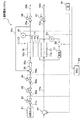
図1に示す本実施形態に係る燃料電池システム1は、図示しない燃料電池自動車(移動体)に搭載されている。燃料電池システム1は、燃料電池スタック10と、燃料電池スタック10を構成する単セル11のカソード電位を検出するための標準水素電極21及び電圧センサ23と、燃料電池スタック10のアノード14に対して水素(燃料ガス)を給排するアノード系(燃料ガス供給手段)と、燃料電池スタック10のカソード15に対して酸素を含む空気(酸化剤ガス)を給排するカソード系と、IG51(イグニッション)等と、これらを電子制御するECU60(Electronic Control Unit、電子制御装置)と、を備えている。
≪Configuration of fuel cell system≫
A
<燃料電池スタック>
燃料電池スタック10は、複数(例えば200〜400枚)の固体高分子型の単セル11が積層して構成されたスタックであり、複数の単セル11は電気的に直列で接続されている。なお、図1では、1つの単セル11のみを記載している。
単セル11は、MEA12(Membrane Electrode Assembly:膜電極接合体)と、これを挟み2枚の導電性を有するアノードセパレータ16及びカソードセパレータ17と、を備えている。MEA12は、1価の陽イオン交換膜等からなる電解質膜13(固体高分子膜)と、これを挟むアノード14及びカソード15(電極)とを備えている。
<Fuel cell stack>
The
The
アノード14及びカソード15は、カーボンペーパ等の導電性を有する多孔質体から主に構成されると共に、アノード14及びカソード15における電極反応を生じさせるための触媒(Pt、Ru等)を含んでいる。
The
アノードセパレータ16には、各MEA12のアノード14に対して水素を給排するための溝や貫通孔が形成されており、これら溝及び貫通孔がアノード流路16a(燃料ガス流路)として機能している。
カソードセパレータ17には、各MEA12のカソード15に対して空気を給排するための溝や貫通孔が形成されており、これら溝及び貫通孔がカソード流路17a(酸化剤ガス流路)として機能している。
The
The
そして、アノード流路16aを介して各アノード14に水素が供給され、カソード流路17aを介して各カソード15に空気が供給されると、電極反応が起こり、各単セル11で電位差(OCV(Open Circuit Voltage)、開回路電圧)が発生するようになっている。次いで、燃料電池スタック10と走行モータ等の外部回路とが電気的に接続され、電流が取り出されると、燃料電池スタック10が発電するようになっている。
Then, when hydrogen is supplied to each
<標準水素電極>
標準水素電極21(Standard Hydrogen Electrode:SHE)は、例えば、多孔質の水素拡散層からなる可逆水素電極(Reversible Hydrogen Electrode:RHE)を用いることができる。これは、カソード電位(カソード電位に関連する電位量)を検出するための基準電極である。標準水素電極21を構成するための水素は、例えば、後記する水素タンク31から、カソード電位の検出時にECU60の指令に従って開かれる常閉型の開閉弁(図示しない)を介して、導かれる。
<Standard hydrogen electrode>
As the standard hydrogen electrode 21 (Standard Hydrogen Electrode: SHE), for example, a reversible hydrogen electrode (RHE) made of a porous hydrogen diffusion layer can be used. This is a reference electrode for detecting the cathode potential (potential amount related to the cathode potential). Hydrogen for constituting the
また、標準水素電極21を構成する電解質溶液が満たされた液路には、カソード15の一部が浸漬されており導通している。さらに、標準水素電極21の電極本体は、カソード電位の検出時にONされるスイッチ22、電圧センサ23(電位量検出手段)を介して、カソード15に接続されている。
Further, a part of the
そして、カソード電位の検出時に、前記開閉弁が開かれ、スイッチ22がONされると、電圧センサ23がカソード電位(vs SHE)を検出し、これをECU60に出力するようになっている。
When the cathode potential is detected, when the on-off valve is opened and the
<アノード系>
アノード系は、水素タンク31(燃料ガス源)と、第1遮断弁32と、減圧弁33(圧力調整手段)と、第2遮断弁34と、エゼクタ35と、パージ弁36と、温度センサ37とを備えている。
水素タンク31は、配管31a、第1遮断弁32、配管32a、減圧弁33、配管33a、第2遮断弁34、配管34a、エゼクタ35、配管35aを介して、アノード流路16aの入口に接続されている。そして、ECU60の指令に従って第1遮断弁32及び第2遮断弁34が開かれると、水素が、水素タンク31から、第1遮断弁32等を経由して、アノード流路16aに供給されるようになっている。減圧弁33は、水素タンク31からアノード流路16aに向かう水素を、所定圧力に減圧させるものである。
<Anode system>
The anode system includes a hydrogen tank 31 (fuel gas source), a first shut-off
The
すなわち、本実施形態では、配管31a、32a、33a、34a、35aによって、アノード流路16aに供給される水素(燃料ガス)の水素供給流路(燃料ガス供給流路)が構成されている。
That is, in this embodiment, the hydrogen supply flow path (fuel gas supply flow path) of hydrogen (fuel gas) supplied to the
アノード流路16aの出口には、配管36a、パージ弁36、配管36bが順に接続されている。また、配管36aの途中は、配管36cを介して、エゼクタ35に接続されている。
A
パージ弁36は常閉型の電磁弁であって、パージ弁36が閉じている場合、アノード流路16aから排出された未反応の水素を含むアノードオフガスがエゼクタ35に戻され、その結果、水素が循環するようになっている。
一方、循環する水素に同伴する水蒸気等の不純物が増加し、セル電圧モニタ(図示しない)を介して単セル11の電圧(セル電圧)が所定セル電圧以下となった場合、ECU60によりパージ弁36が開かれ、水蒸気等の不純物が、配管36bを介して、車外に排出されるようになっている。
The
On the other hand, when impurities such as water vapor accompanying the circulating hydrogen increase and the voltage (cell voltage) of the
温度センサ37(燃料電池温度検出手段)は、配管36aに配置されており、アノード流路16aから排出されたアノードオフガスの温度を、燃料電池スタック10の温度として検出し、ECU60に出力するようになっている。
ただし、燃料電池スタック10の温度を検出する温度センサ37の位置は、これに限定されず、カソードオフガスが流通する配管42a、燃料電池スタック10から排出された冷媒が流通する配管(図示しない)、燃料電池スタック10の筐体に配置する構成としてもよい。また、温度センサ37を複数設け、誤検出を防止してもよい。
The temperature sensor 37 (fuel cell temperature detection means) is arranged in the
However, the position of the
<カソード系>
カソード系は、コンプレッサ41(酸化剤ガス供給手段)と、背圧弁42(圧力調整手段)とを備えている。
コンプレッサ41は、配管41aを介して、カソード流路17aの入口に接続されており、ECU60の指令に従って作動すると、酸素を含む空気を取り込み、カソード流路17aに供給するようになっている。なお、配管41aには、カソード流路17aに向かう空気を適宜に加湿する加湿器(図示しない)が設けられている。
<Cathode system>
The cathode system includes a compressor 41 (oxidant gas supply means) and a back pressure valve 42 (pressure adjustment means).
The
カソード流路17aの出口には、配管42a、背圧弁42、配管42bが接続されており、カソード流路17aから排出されたカソードオフガスが、配管42a等を介して車外(外部)に排出されるようになっている。背圧弁42は、ECU60の指令に従って、背圧、つまり、カソード流路17a内のガスの圧力を調整するようになっている。
A
<IG>
IG51は、燃料電池自動車及び燃料電池システム1の起動スイッチであり、運転席周りに設けられている。また、IG51はECU60と接続されており、ECU60はIG51のON/OFF信号を検知するようになっている。
<IG>
The
<ECU>
ECU60(制御手段、電位量記憶手段)は、燃料電池システム1を電子制御する制御装置であり、CPU、ROM、RAM、各種インタフェイス、電子回路などを含んで構成されており、その内部に記憶されたプログラムに従って、各種機器を制御し、各種処理を実行するようになっている。
なお、ECU60による具体的制御内容は、図2のフローチャート等を参照して、以下詳細に説明する。
<ECU>
The ECU 60 (control means, potential amount storage means) is a control device that electronically controls the
The specific control contents by the
≪燃料電池システムの動作≫
次に、図2を主に参照して、燃料電池システム1の動作を、ECU60に設定されたプログラム(フローチャート)の流れと共に説明する。
なお、IG51がOFFされると、図2に示す処理がスタートする。また、初期状態(IG51のOFF前)において、第1遮断弁32及び第2遮断弁34は開くと共に、コンプレッサ41は作動しており、燃料電池スタック10は発電している。
≪Operation of fuel cell system≫
Next, mainly referring to FIG. 2, the operation of the
Note that when the
ステップS101において、ECU60は、第1遮断弁32及び第2遮断弁34を閉じ、アノード流路16aへの水素の供給を停止する。また、ECU60は、コンプレッサ41を停止し、カソード流路17aへの空気の供給を停止する。さらに、ECU60は、燃料電池スタック10と走行モータ等を含む外部回路との接続をOFFし、燃料電池スタック10の発電を停止させる。
また、ここでは、燃料電池スタック10の発電停止後において、背圧弁42が開放される場合を例示する。
In step S101, the
Further, here, the case where the
ステップS102において、ECU60は、温度センサ37を介して、発電停止時における燃料電池スタック10の温度を検出し、これを内部メモリ(RAM等)に記憶する。
In step S102, the
ステップS103において、ECU60は、内部クロックを利用して、ステップS101、後記するステップS105の判定結果がNo、又は、後記するステップS109の後、所定時間Δt経過したか否かを判定する。所定時間Δt1(例えば5分)は、燃料電池スタック10の発電停止後、カソード電位の上昇を抑えるべく、カソード電位を定期的に検出する時間であり、事前試験等により求められ、ECU60に予め記憶されている。
なお、所定時間Δt1を可変、例えば、燃料電池スタック10の発電停止からの時間が経過するにつれて、所定時間Δt1を徐々に長くする構成としてもよい。
In step S103, the
Note that the predetermined time Δt1 may be variable, for example, the predetermined time Δt1 may be gradually increased as time elapses after the
所定時間Δt1経過したと判定された場合(S103・Yes)、ECU60の処理はステップS104に進む。一方、所定時間Δt1経過していないと判定された場合(S103・No)、ECU60の処理はステップS103の判定を繰り返す。
When it is determined that the predetermined time Δt1 has elapsed (S103: Yes), the process of the
ステップS104において、ECU60(電位量記憶手段)は、電圧センサ23を介して、カソード電位(今回カソード電位)を検出する。そして、ECU60は、検出された今回カソード電位を、内部メモリ(RAM等)に記憶する。
In step S104, the ECU 60 (potential amount storage means) detects the cathode potential (current cathode potential) via the
なお、この後、後記するステップS105の判定結果がNo、又は、ステップS109の後、ステップS103の判定結果がYesとなりステップS104に進んだ場合も、ECU60は、再び、カソード電位を検出し、これを記憶する。
After that, even if the determination result in step S105 described later is No, or after step S109, the determination result in step S103 is Yes and the process proceeds to step S104, the
すなわち、燃料電池スタック10の発電停止後、所定時間Δt1が経過する毎に、ステップS104の処理が実行される。そして、ECU60には、初回を除き、今回のステップS104で検出されたカソード電位(今回カソード電位)と、前回のステップS104で検出されたカソード電位(前回セル電圧)とが記憶される。
That is, the process of step S104 is executed every time the predetermined time Δt1 elapses after the
ステップS105において、ECU60は、内部メモリに記憶されている、今回カソード電位と前回カソード電位との差が、所定値(所定電位量差)以上であるか否かを判定する。
今回カソード電位と前回カソード電位との差が、所定値以上であると判定された場合(S105・Yes)、ECU60の処理はステップS106に進む。一方、今回カソード電位と前回カソード電位との差が、所定値以上でないと判定された場合(S105・No)、ECU60の処理は、ステップS103に進む。
なお、ステップS105における初回判定では、判定結果がNoとなるように設定されている。
In step S105, the
If it is determined that the difference between the current cathode potential and the previous cathode potential is greater than or equal to a predetermined value (S105, Yes), the process of the
In the initial determination in step S105, the determination result is set to No.
ここで、燃料電池スタック10の発電停止後におけるアノード電位(vs SHE)、カソード電位(vs SHE)、セル電圧(カソード電位−アノード電位)の動きを、図5を参照して説明する。
アノード電位は、発電停止時において略0である。そして、発電停止後、カソード流路17aからアノード流路16aに空気がリークするが、アノード電位は、継続して略0を示す。
Here, the movement of the anode potential (vs SHE), the cathode potential (vs SHE), and the cell voltage (cathode potential−anode potential) after power generation stop of the
The anode potential is substantially zero when power generation is stopped. After the power generation is stopped, air leaks from the
カソード電位は、発電停止時においては、MEA12の仕様、カソード流路17aの設定圧力等に応じて、例えば、0.7〜0.9V程度を示す。その後、時間が経過すると、アノード流路16aに残留する水素が、電解質膜13を透過して、カソード流路17aにリークし、リークした水素がカソード15に含まれる触媒下で電極反応すると、カソード電位及びセル電圧が低下する。
The cathode potential is about 0.7 to 0.9 V, for example, depending on the specifications of the
そして、カソード流路17aの上流及び下流は、開いたままの背圧弁42等を介して車外(外部)に開放されているので、リークした水素は車外に流出すると共に、車外からカソード流路17aに空気が流入する。このようにカソード流路17aに空気が流入すると、空気中の酸素がカソード15の触媒下で電極反応し、カソード電位及びセル電圧が上昇する傾向となる(図5の符号A、B参照)。
次いで、カソード流路17aの空気は、電解質膜13を透過し、アノード流路16aにリークし始める。
Since the upstream and downstream sides of the
Next, the air in the
アノード流路16aに空気がリークすると、リークした空気中の酸素がアノード14の触媒下で電極反応し、アノード電位が上昇する傾向となる(図5の符号C参照)。これに対して、カソード電位は上昇したままであるので、アノード電位が上昇すると、セル電圧が低下する傾向となる(図5の符号D参照)。
When air leaks into the
そして、このようにカソード電位が上昇している状態で、IG51がONされ、このON信号を検知したECU60が、燃料電池システム1を再起動するべく、コンプレッサ41を作動させ、カソード流路17aに新たに空気を導入すると、この導入された空気中の酸素が電極反応し、カソード電位が上昇し(図5の符号E参照)、燃料電池スタック10及びMEA12の設計時に予定されていた上限カソード電位V1よりも高くなる。
一方、アノード流路16aには、水素が新たに供給され、この水素が電極反応するので、アノード電位は低下する(図5の符号F参照)。
Then, the
On the other hand, hydrogen is newly supplied to the
そうすると、セル電圧が大きく上昇し(図5の符号G参照)、設計時に予定されていた上限セル電圧ΔV1よりも高くなる。そして、このような状態で電流が取り出されると、予定よりも大きな電流が流れ、MEA12等が劣化する虞がある。
As a result, the cell voltage greatly increases (see symbol G in FIG. 5), and becomes higher than the upper limit cell voltage ΔV1 scheduled at the time of design. If a current is taken out in such a state, a current larger than planned flows and the
また、カソード電位の上昇程度は、カソード15に含まれる触媒の活性の程度に関係し、触媒の活性が高いほど、つまり、触媒の温度が高いほど、カソード電位は大きく上昇する傾向となる。したがって、発電停止時における燃料電池スタック10の温度が高いほど、また、発電停止からの経過時間が短いほど、カソード電位は大きく上昇する傾向となる。
Further, the degree of increase in the cathode potential is related to the degree of activity of the catalyst contained in the
本実施形態では、このようなアノード電位、カソード電位、及び、セル電位の動きを考慮した上で、今回カソード電位と前回カソード電位との差が、所定値以上である場合(S105・Yes)、アノード流路16aに水素を供給し、水素をカソード流路17aにリークさせ、カソード電位の上昇を抑えることを特徴とする。
In the present embodiment, in consideration of the movement of the anode potential, the cathode potential, and the cell potential, when the difference between the current cathode potential and the previous cathode potential is equal to or greater than a predetermined value (Yes in S105), Hydrogen is supplied to the
そして、システムが再起動し、カソード流路17aに空気が新たに供給され、カソード電位が上昇しても、カソード電位が上限カソード電位V1以下となるように、つまり、発電停止後から再起動前のカソード電位が、発電停止後から再起動前の上限カソード電位V2以下となるように、カソード電位の上昇を抑えることを特徴とする。
なお、発電停止後から再起動前の上限カソード電位V2は、例えば、上限カソード電位V1から、再起動時におけるカソード電位の上昇量(ΔV5)を減じた電位に設定される。
Then, even when the system is restarted and air is newly supplied to the
Note that the upper limit cathode potential V2 after the power generation is stopped and before the restart is set to, for example, a potential obtained by subtracting the increase amount (ΔV5) of the cathode potential at the time of restart from the upper limit cathode potential V1.
したがって、ステップS105において判定基準となる所定値は、ステップS103における所定時間Δt1と関係すると共に(所定時間Δt1が短くなると、所定値は小さくなる)、MEA12等の仕様に関係し、IG51がONされ、システムが再起動し、カソード電位がΔV5上昇しても、上昇後のカソード電位が上限カソード電位V1以下となり、MEA12等が劣化しない値に設定される。そして、このような所定値は、事前試験等により求められ、ECU60に予め記憶されている。
Therefore, the predetermined value that becomes the determination criterion in step S105 is related to the predetermined time Δt1 in step S103 (the predetermined value becomes smaller as the predetermined time Δt1 becomes shorter), and related to the specifications of the
図2に戻って説明を続ける。
ステップS106において、ECU60は、今回カソード電位と前回カソード電位との差(電位量差)及び発電停止時の燃料電池スタック10の温度と、図3のマップとに基づいて、アノード流路16aに供給すべき水素の量(目標供給量)、及び、第2遮断弁34の開時間Δt2(水素供給時間、目標供給量)を算出する。次いで、発電停止からの時間と図4のマップと基づいて補正係数Xを求め、第2遮断弁34の開時間Δt2に補正係数Xを乗算し、補正する。
Returning to FIG. 2, the description will be continued.
In step S106, the
なお、図3及び図4のマップは、事前試験等により求められ、ECU60に予め記憶されている。
図3に示すように、今回カソード電位と前回カソード電位との差が大きいほど、発電停止時における燃料電池スタック10の温度が高いほど、第2遮断弁34の開時間Δt2が長くなるように、つまり、アノード流路16aに供給され、カソード流路17aにリークする水素供給量が多くなるように設定されている。
3 and 4 are obtained by a preliminary test or the like and stored in the
As shown in FIG. 3, the larger the difference between the current cathode potential and the previous cathode potential, and the higher the temperature of the
図4に示すように、補正係数Xは、発電停止時は1であり、発電停止から時間が経過するにつれて徐々に大きくなるように設定されている。これにより、発電停止から時間が経過するほど、第2遮断弁34の開時間Δt2が長くなり、カソード流路17aにリークする水素が多くなるように設定されている。
As shown in FIG. 4, the correction coefficient X is 1 when power generation is stopped, and is set to gradually increase as time elapses from the stop of power generation. As a result, the opening time Δt2 of the second shut-off
ステップS107において、ECU60は、第1遮断弁32を閉じたまま、第2遮断弁34を開く。
ここで、アノード流路16aの残留水素は、電解質膜13を透過して、カソード流路17aにリークしているので、アノード流路16aを含む第2遮断弁34の下流側の圧力は、第1遮断弁32と減圧弁33との間における圧力(減圧弁33の一次側圧力)よりも低い状況となっている。
In step S107, the
Here, since the residual hydrogen in the
このような状況において、第2遮断弁34が開かれると、減圧弁33が開き、配管32a内の残留水素が、減圧弁33の下流に流れ込み、アノード流路16aに水素が供給される。
すなわち、本実施形態において、配管32aは、燃料電池スタック10の発電停止後に、アノード流路16aに供給する水素を一時的に貯溜するためのバッファ部として機能している。よって、配管32aを例えば部分的に太くし、水素の貯溜量を大きくする構成としてもよい。
In such a situation, when the second shut-off
That is, in the present embodiment, the
次いで、アノード流路16aに供給された水素は、電解質膜13を透過し、カソード流路17aにリークする。そうすると、カソード流路17aにおける水素濃度が高くなると共に、水素の一部は、カソード15の触媒下で反応し、その結果、カソード電位及びセル電圧が低下する(図5の符号H、I参照)。
Next, the hydrogen supplied to the
ステップS108において、ECU60は、内部クロックを利用して、ステップS107で第2遮断弁34を開いた後、ステップS106で算出された補正後の開時間Δt2が経過したか否かを判定する。
補正後の開時間Δt2経過したと判定された場合(S108・Yes)、ECU60の処理はステップS109に進む。補正後の開時間Δt2経過していないと判定された場合(S108・No)、ECU60の処理はステップS108の判定を繰り返す。
In step S108, the
When it is determined that the corrected open time Δt2 has elapsed (S108, Yes), the process of the
ステップS109において、ECU60は、第2遮断弁34を閉じる。
その後、ECU60の処理は、ステップS103に進む。
In step S109, the
Thereafter, the processing of the
≪燃料電池システムの効果≫
このような燃料電池システム1によれば、次の効果を得る。
燃料電池スタック10の発電停止後において、所定時間Δt1経過毎に、繰り返して、今回カソード電位を検出し、今回カソード電位と前回カソード電位との差が所定値以上である場合、アノード流路16aに水素を供給し、水素をカソード流路17aにリークさせるので、カソード電位の上昇を抑えることができる。
これにより、その後にIG51がONされ、燃料電池システム1が再起動し、カソード流路17aに新たに空気が供給されたとしても、カソード電位及びセル電圧が、MEA12等が劣化する上限カソード電位V1及び上限セル電圧ΔV1よりも高くなることは、防止される。
≪Effect of fuel cell system≫
According to such a
After the power generation of the
As a result, even after the
また、第2遮断弁34の開時間Δt2、つまり、カソード流路17aにリークさせる水素の量は、今回カソード電位と前回カソード電位との差、発電停止時における燃料電池スタック10の温度、発電停止からの時間に基づいて、適切に求めることができる。
Further, the opening time Δt2 of the
さらに、燃料電池システム1は、燃料ガス源である水素タンク31からアノード流路16aに向かって順に、第1遮断弁32、減圧弁33、第2遮断弁34を備えるので、第2遮断弁34を開くことにより、アノード流路16aに水素を供給することができる。
Furthermore, since the
以上、本発明の一実施形態について説明したが、本発明は前記実施形態に限定されず、本発明の趣旨を逸脱しない範囲で、例えば次のように変更することができる。 As mentioned above, although one Embodiment of this invention was described, this invention is not limited to the said embodiment, For example, it can change as follows in the range which does not deviate from the meaning of this invention.
前記した実施形態では、燃料電池スタック10の発電停止後(燃料電池システム1の停止後)、背圧弁42が開放される構成を例示したが、燃料電池スタック10の発電停止後、背圧弁42を閉じ、外部から配管42b等を介してカソード流路17aへの空気の流入を低減する構成に、本発明を適用してもよい。
この構成の場合、カソード流路17aに流入する空気が減少するので、カソード電位の上昇が遅れることになる。ただし、停止中に氷点下等の低温環境に曝される場合、背圧弁42が完全に閉じたまま凍結することを防止するため、背圧弁42は小さい開度にて開いたままにすることが好ましい。
In the embodiment described above, the
In the case of this configuration, since the air flowing into the
前記した実施形態では、発電停止後にカソード電位が上昇した場合、第2遮断弁34を開き、配管32a内の残留水素をアノード流路16aに供給する構成を例示したが、さらに、第1遮断弁32を開き、水素タンク31内の水素を供給する構成としてもよい。
また、例えば、配管35aから分岐するように、水素を一時的に貯溜するタンクを設け、このタンクからアノード流路16aに水素を供給する構成としてもよい。
In the above-described embodiment, when the cathode potential rises after power generation is stopped, the second shut-off
Further, for example, a tank for temporarily storing hydrogen may be provided so as to branch from the
前記した実施形態では、発電停止後に、水素をアノード流路16aに供給し、そして、水素をカソード流路17aにリークさせることで、カソード電位の上昇を抑える構成としたが、その他に例えば、適宜な配管を介して、カソード流路17aに水素を直接供給する構成としてもよい。
In the above-described embodiment, after power generation is stopped, hydrogen is supplied to the
前記した実施形態では、発電停止後におけるアノード流路16aへの水素供給を、第2遮断弁34の開時間(水素の供給時間)に基づいて制御したが、その他に例えば、配管32aに圧力センサを設けて、圧力変化に基づいて制御してもよい。また、第1遮断弁32を開き、水素タンク31からも水素を供給する場合、例えば、配管31aに圧力センサを設けるとよい。
また、アノード流路16aの圧力を検出する圧力センサを設けて、アノード流路16aの圧力が所定圧力に到達した場合(所定圧力上昇した場合)、水素が供給されたと予想して、水素供給を停止する構成としてもよい。
In the above-described embodiment, the hydrogen supply to the
Further, a pressure sensor for detecting the pressure of the
前記した実施形態では、発電停止後にカソード電位を検出し、カソード電位の変化量に基づいて水素を供給する構成としたが、その他に例えば、発電停止後にアノード流路16aに空気がリークし、アノード電位が上昇した場合、カソード電位も上昇していると予想されるので、アノード電位の変化量、つまり、アノード電位が上昇したとき、水素を供給する構成としてもよい。
In the above-described embodiment, the cathode potential is detected after power generation is stopped, and hydrogen is supplied based on the amount of change in the cathode potential. For example, air leaks into the
また、発電停止後、カソード電位の低下に伴って、セル電圧が低下し、その後、カソード電位の上昇に伴って、セル電圧が上昇するので、セル電圧が一旦低下した後に上昇した場合、カソード電位が上昇していると予想して、水素を供給する構成としてもよい。 In addition, after power generation stops, the cell voltage decreases as the cathode potential decreases, and then the cell voltage increases as the cathode potential increases. It is good also as a structure which supplies hydrogen in anticipation of having risen.
さらに、カソード流路17aへのリークにより、カソード流路17aの水素濃度が一旦高くなった後、水素が車外に流出し、水素濃度が低下すると、カソード電位が上昇するので、カソード流路17aにおける水素濃度を検出する水素センサを適所に設け、水素濃度の変化に基づいて、水素供給を制御する構成としてもよい。
Furthermore, after the hydrogen concentration in the
さらにまた、発電停止後、カソード電位は一旦低下した後に上昇するので、発電停止から所定時間経過した後、カソード電位は上昇していると予想して、発電停止からの経過時間に基づいて水素供給を制御する構成としてもよい。 Furthermore, after power generation stops, the cathode potential once decreases and then rises. Therefore, after a predetermined time has elapsed since power generation stopped, the cathode potential is expected to increase, and hydrogen is supplied based on the elapsed time since power generation stopped. It is good also as a structure which controls.
1 燃料電池システム
10 燃料電池スタック
11 単セル
12 MEA
13 電解質膜
14 アノード
15 カソード
16a アノード流路(燃料ガス流路)
17a カソード流路(酸化剤ガス流路)
21 標準水素電極
23 電圧センサ(電位量検出手段)
31 水素タンク(燃料ガス源、燃料ガス供給手段)
32 第1遮断弁(燃料ガス供給手段)
33 減圧弁(圧力調整手段、燃料ガス供給手段)
34 第2遮断弁(燃料ガス供給手段)
37 温度センサ(燃料電池温度検出手段)
60 ECU(電位量記憶手段、制御手段)
V1 起動時における上限カソード電位
V2 発電停止中における上限カソード電位
ΔV1 起動時における上限セル電圧
Δt2 第2遮断弁34の開時間(水素供給時間、目標供給量)
DESCRIPTION OF
13
17a Cathode channel (oxidant gas channel)
21
31 Hydrogen tank (fuel gas source, fuel gas supply means)
32 1st shut-off valve (fuel gas supply means)
33 Pressure reducing valve (pressure adjusting means, fuel gas supplying means)
34 Second shut-off valve (fuel gas supply means)
37 Temperature sensor (Fuel cell temperature detection means)
60 ECU (potential amount storage means, control means)
V1 Upper limit cathode potential at start-up V2 Upper limit cathode potential at power generation stop ΔV1 Upper limit cell voltage at start-up Δt2 Second shut-off
Claims (6)
前記燃料ガス流路に燃料ガスを供給する燃料ガス供給手段と、
前記燃料電池の発電停止後に、所定時間経過毎に、当該燃料電池のカソード電位に関する電位量を検出する電位量検出手段と、
前記電位量検出手段が検出した電位量を記憶する電位量記憶手段と、
今回の電位量と前回の電位量との差である電位量差を算出し、算出した電位量差が所定電位量差以上である場合、再起動によりカソード電位が上昇しても前記燃料電池の劣化しないカソード電位以下となるように、今回の電位量差に基づいて燃料ガスの目標供給量を算出し、算出した目標供給量の燃料ガスが前記燃料ガス流路に供給されるように、前記燃料ガス供給手段を制御する制御手段と、
を備え、
前記燃料電池の発電停止中、前記酸化剤ガス流路が外部と連通する
ことを特徴とする燃料電池システム。 A fuel cell having a fuel gas channel and an oxidant gas channel, wherein fuel gas is generated by supplying fuel gas to the fuel gas channel and oxidant gas to the oxidant gas channel;
Fuel gas supply means for supplying fuel gas to the fuel gas flow path;
A potential amount detection means for detecting a potential amount related to the cathode potential of the fuel cell every predetermined time after power generation of the fuel cell is stopped;
A potential amount storage means for storing the potential amount detected by the potential amount detection means;
When the potential difference, which is the difference between the current potential amount and the previous potential amount, is calculated and the calculated potential amount difference is equal to or greater than the predetermined potential amount difference, the fuel cell The target supply amount of the fuel gas is calculated based on the current potential difference so that the cathode potential does not deteriorate or less, and the calculated target supply amount of fuel gas is supplied to the fuel gas flow path. Control means for controlling the fuel gas supply means;
Equipped with a,
The fuel cell system , wherein the oxidant gas flow path communicates with the outside during power generation stop of the fuel cell.
ことを特徴とする請求項1に記載の燃料電池システム。 The fuel cell system according to claim 1, wherein the target supply amount is set to increase as the current potential difference increases.
ことを特徴とする請求項1又は請求項2に記載の燃料電池システム。 3. The fuel cell system according to claim 1, wherein the target supply amount is set to increase as the elapsed time from the power generation stop of the fuel cell is shorter.
ことを特徴とする請求項1から請求項3のいずれか1項に記載の燃料電池システム。 The fuel cell system according to any one of claims 1 to 3, wherein the target supply amount is set to increase as the temperature of the fuel cell at the time of stopping power generation increases.
前記燃料ガス源の燃料ガスが、前記第1遮断弁、前記圧力調整手段、前記第2遮断弁を順に介して、前記燃料ガス流路に供給され、
前記燃料電池の発電を停止させる場合、前記第1遮断弁及び前記第2遮断弁が閉じられ、
前記燃料電池の発電停止後において前記燃料ガス流路に燃料ガスを供給する場合、前記制御手段は、前記第1遮断弁を閉じたまま、前記第2遮断弁を開く
ことを特徴とする請求項1から請求項4のいずれか1項に記載の燃料電池システム。 The fuel gas supply means includes a fuel gas source, a first cutoff valve, a pressure adjustment means, and a second cutoff valve,
The fuel gas of the fuel gas source is supplied to the fuel gas flow path through the first cutoff valve, the pressure adjusting means, and the second cutoff valve in this order,
When stopping the power generation of the fuel cell, the first cutoff valve and the second cutoff valve are closed,
When supplying fuel gas to the fuel gas flow path after stopping the power generation of the fuel cell, the control means opens the second shutoff valve while keeping the first shutoff valve closed. The fuel cell system according to any one of claims 1 to 4.
前記燃料電池の発電停止後、前記制御手段は、前記背圧弁を閉じ、外部から前記酸化剤ガス流路への空気の流入を低減する After stopping the power generation of the fuel cell, the control means closes the back pressure valve to reduce the inflow of air from the outside to the oxidant gas flow path.
ことを特徴とする請求項1から請求項5のいずれか1項に記載の燃料電池システム。 The fuel cell system according to any one of claims 1 to 5, wherein
Priority Applications (1)
| Application Number | Priority Date | Filing Date | Title |
|---|---|---|---|
| JP2007285764A JP5199645B2 (en) | 2007-11-02 | 2007-11-02 | Fuel cell system |
Applications Claiming Priority (1)
| Application Number | Priority Date | Filing Date | Title |
|---|---|---|---|
| JP2007285764A JP5199645B2 (en) | 2007-11-02 | 2007-11-02 | Fuel cell system |
Publications (3)
| Publication Number | Publication Date |
|---|---|
| JP2009117056A JP2009117056A (en) | 2009-05-28 |
| JP2009117056A5 JP2009117056A5 (en) | 2009-11-05 |
| JP5199645B2 true JP5199645B2 (en) | 2013-05-15 |
Family
ID=40784000
Family Applications (1)
| Application Number | Title | Priority Date | Filing Date |
|---|---|---|---|
| JP2007285764A Expired - Fee Related JP5199645B2 (en) | 2007-11-02 | 2007-11-02 | Fuel cell system |
Country Status (1)
| Country | Link |
|---|---|
| JP (1) | JP5199645B2 (en) |
Families Citing this family (5)
| Publication number | Priority date | Publication date | Assignee | Title |
|---|---|---|---|---|
| JP5112525B2 (en) * | 2010-05-18 | 2013-01-09 | 本田技研工業株式会社 | Starting method for polymer electrolyte fuel cell |
| JP5577905B2 (en) * | 2010-07-14 | 2014-08-27 | トヨタ自動車株式会社 | FUEL CELL SYSTEM AND CONTROL METHOD FOR FUEL CELL SYSTEM |
| JP5605106B2 (en) * | 2010-09-13 | 2014-10-15 | パナソニック株式会社 | Fuel cell power generator |
| JP2012074329A (en) * | 2010-09-30 | 2012-04-12 | Hitachi Ltd | Fuel cell system |
| CN114583218B (en) * | 2020-11-30 | 2024-02-09 | 宇通客车股份有限公司 | Fuel cell system, hydrogen system bottle valve fault detection method and device |
Family Cites Families (2)
| Publication number | Priority date | Publication date | Assignee | Title |
|---|---|---|---|---|
| JP2005251434A (en) * | 2004-03-01 | 2005-09-15 | Matsushita Electric Ind Co Ltd | Fuel cell system, and control method of fuel cell |
| JP2007026808A (en) * | 2005-07-14 | 2007-02-01 | Nissan Motor Co Ltd | Fuel cell system |
-
2007
- 2007-11-02 JP JP2007285764A patent/JP5199645B2/en not_active Expired - Fee Related
Also Published As
| Publication number | Publication date |
|---|---|
| JP2009117056A (en) | 2009-05-28 |
Similar Documents
| Publication | Publication Date | Title |
|---|---|---|
| JP4644064B2 (en) | Fuel cell system | |
| JP5957664B2 (en) | Fuel cell system and operation method thereof | |
| JP5231750B2 (en) | Fuel cell system | |
| CN102484271A (en) | Control Device And Control Method For Fuel Cell System | |
| JP2008269841A (en) | Fuel cell system | |
| JP5199645B2 (en) | Fuel cell system | |
| JPWO2012115196A1 (en) | Fuel cell system | |
| JP5186794B2 (en) | Fuel cell system and gas pressure adjustment method in fuel cell system | |
| JPWO2013129453A1 (en) | FUEL CELL SYSTEM AND CONTROL METHOD FOR FUEL CELL SYSTEM | |
| WO2013180080A1 (en) | Fuel cell system and control method for fuel cell system | |
| CN115241492A (en) | Hydrogen storage system | |
| JP2009054427A (en) | Fuel cell system | |
| US9059438B2 (en) | Fuel cell system | |
| JP2008004564A (en) | Power generation shutdown method of fuel cell system | |
| JP2004179054A (en) | Power generation shutdown method of fuel cell system | |
| EP2224527B1 (en) | Fuel cell system and method for controlling the same | |
| JP6155870B2 (en) | Fuel cell system | |
| JP5097016B2 (en) | Fuel cell system and method for determining open / close state of shut-off valve | |
| CN116742069A (en) | Fuel cell system and valve control method for fuel cell system | |
| JP6028347B2 (en) | Fuel cell system | |
| JP2013246935A (en) | Fuel cell system | |
| JP2013182688A (en) | Fuel cell system | |
| JP2012209154A (en) | Control device for controlling fuel cell system | |
| JP5144152B2 (en) | Discharge system | |
| JP2012059557A (en) | Fuel cell system |
Legal Events
| Date | Code | Title | Description |
|---|---|---|---|
| A521 | Written amendment |
Free format text: JAPANESE INTERMEDIATE CODE: A523 Effective date: 20090916 |
|
| A621 | Written request for application examination |
Free format text: JAPANESE INTERMEDIATE CODE: A621 Effective date: 20090916 |
|
| A977 | Report on retrieval |
Free format text: JAPANESE INTERMEDIATE CODE: A971007 Effective date: 20120625 |
|
| A131 | Notification of reasons for refusal |
Free format text: JAPANESE INTERMEDIATE CODE: A131 Effective date: 20120703 |
|
| A521 | Written amendment |
Free format text: JAPANESE INTERMEDIATE CODE: A523 Effective date: 20120824 |
|
| TRDD | Decision of grant or rejection written | ||
| A01 | Written decision to grant a patent or to grant a registration (utility model) |
Free format text: JAPANESE INTERMEDIATE CODE: A01 Effective date: 20130129 |
|
| A61 | First payment of annual fees (during grant procedure) |
Free format text: JAPANESE INTERMEDIATE CODE: A61 Effective date: 20130208 |
|
| FPAY | Renewal fee payment (event date is renewal date of database) |
Free format text: PAYMENT UNTIL: 20160215 Year of fee payment: 3 |
|
| R150 | Certificate of patent or registration of utility model |
Ref document number: 5199645 Country of ref document: JP Free format text: JAPANESE INTERMEDIATE CODE: R150 Free format text: JAPANESE INTERMEDIATE CODE: R150 |
|
| LAPS | Cancellation because of no payment of annual fees |