JP4029178B2 - Eddy current flaw detection method and apparatus - Google Patents
Eddy current flaw detection method and apparatus Download PDFInfo
- Publication number
- JP4029178B2 JP4029178B2 JP2003013436A JP2003013436A JP4029178B2 JP 4029178 B2 JP4029178 B2 JP 4029178B2 JP 2003013436 A JP2003013436 A JP 2003013436A JP 2003013436 A JP2003013436 A JP 2003013436A JP 4029178 B2 JP4029178 B2 JP 4029178B2
- Authority
- JP
- Japan
- Prior art keywords
- cast iron
- eddy current
- iron pipe
- sensor
- circumferential direction
- Prior art date
- Legal status (The legal status is an assumption and is not a legal conclusion. Google has not performed a legal analysis and makes no representation as to the accuracy of the status listed.)
- Expired - Fee Related
Links
Images


Landscapes
- Investigating Or Analyzing Materials By The Use Of Magnetic Means (AREA)
Description
【0001】
【発明の属する技術分野】
本発明はE型渦流センサを用いた鋼管の表面疵検出方法およびその装置に関し、特に遠心鋳造による鋳鉄管の地肌筋に沿って発生する表面疵検出に優れるものに関する。
【0002】
【従来の技術】
渦流センサは、計測対象に発生させる渦電流が表面性状や内部組織により変化することを利用するもので、非接触での計測が可能で、且つ検出回路の調整により種々の対象に即した検出信号が得られるため、鉄鋼プロセスの計測手段として連続鋳造の湯面計や薄板製品の表面疵検出など多方面に用いられている。
【0003】
特許文献1は鋳鉄管探傷装置に関し、鋳鉄管表面の凹凸の影響を受けずにクラックを検出するため渦流探傷ヘッドとして駆動コイルの両端に誘導コイルを配置したものを用い、更に複数個の渦流探傷ヘッドを鋳鉄管の周方向に並べる際、隣接する渦流探傷ヘッドの端部が互いに重なり合うように千鳥状に配置することを特徴とする。
【0004】
本技術によればクラックに対する検出感度を向上させ、且つ検査能率を向上させることが可能であるが、隣接する渦流探傷ヘッドの相互干渉を防ぐため、駆動周波数を異なるものとする必要があり、また渦流探傷ヘッドを取付ける装置は鋳鉄管の半周または全周を覆い、管軸方向に移動する機構を有するなど大掛かりなものとなっている。
【0005】
一部の工場では図6に示す鋳鉄管疵検出装置100が用いられている。本装置は鋳鉄管101を全周方向で覆うフレーム103を設け、該フレーム103に渦流センサを取付けたセンサヘッド102を鋳鉄管の全円周方向から同時に計測可能なように複数個取付け、鋳鉄管101またはフレーム103を管軸方向に移動させることを特徴とする。
【0006】
本装置を用いると短時間に鋳鉄管全長の計測が可能で能率的であるが、フレーム内で精度良く管中心軸を位置決めする機構や位置決め精度を保ちつつフレームを管軸方向に駆動する装置が必要で設備的負荷が大きく高価な装置となっている。
【0007】
【特許文献1】
特公昭59−7940号公報
【0008】
【発明が解決しようとする課題】
上述したように、既存の鋳鉄管表面疵検出装置は設備的負荷が大きく、更に特許文献1のように渦流探傷ヘッドとして駆動コイルの両端に誘導コイルを配置したものを用いても、遠心鋳造によるスパイラル状の地肌疵に沿った直折れと呼ばれる表面疵に対し、十分な検出感度が得られず、検出しきれない場合があった。
【0009】
本発明は表面疵検出感度が高い疵検出方法および装置を提供することを目的とする。
【0010】
【課題を解決するための手段】
本発明の目的は以下の手段により達成できる。
【0011】
請求項1記載の発明は、遠心鋳造により製造された鋳鉄管に対し、E型渦流センサをその両端の検出コイルが前記鋳鉄管円周方向に縦に並ぶように配置し、前記E型渦流センサの計測軌跡を前記鋳鉄管地肌筋に対し逆スパイラル状とすることに特徴を有するものである。
【0012】
請求項2記載の発明は、E型渦流センサを両端の検出コイルが遠心鋳造により製造された鋳鉄管の円周方向に縦に並ぶように取付けた複数台のセンサヘッドを所定の間隔を保持しながら前記鋳鉄管の管軸方向に平行移動させる手段と、前記鋳鉄管を円周方向に回転させる手段とを備え、前記センサヘッドの計測軌跡が、鋳鉄管地肌筋と逆方向のスパイラルとなるように前記センサヘッドを平行移動させつつ前記鋳鉄管を円周方向に回転させることに特徴を有するものである。
【0013】
請求項3記載の発明は、請求項1記載の発明において、前記E型渦流センサを複数個設け、前記複数個のE型渦流センサを前記逆スパイラル状の計測軌跡に沿って並ぶように配置したことに特徴を有するものである。
【0014】
請求項4記載の発明は、請求項2記載の発明において、前記複数個のE型渦流センサは、前記逆スパイラル状の計測軌跡に沿って並ぶように配置されていることに特徴を有するものである。
【0015】
【発明の実施の形態】
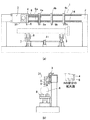
本発明の実施の形態を図を用いて詳細に説明する。図1に本発明の一実施形態に係る渦流探傷装置の構成を示す概略図を示す。図1において(a)は正面図、(b)は側面図で、1は渦流探傷装置全体、2は架台、3は移動台車、31は移動用モータ、4、4a、4b,4cはセンサヘッド、5、5a,5b,5cはE型渦流センサ、6,6aはガイドレール、7はローラ駆動モータ、8は昇降式ターニングローラ、11は昇降モータ、14は移動台車3に固定され、センサヘッド4、4aが取付けられる棒状部材を示す。
【0016】
渦流探傷装置1はE型渦流センサ5を取付けたセンサヘッド4を所定の間隔を保持しながら鋳鉄管9の管軸方向に平行移動させる手段と鋳鉄管9を円周方向に回転させる手段とを備え、図2に示すように鋳鉄管9を円周方向に回転させながら、センサヘッド10を移動し、疵検出を行う。
【0017】
E型渦流センサを所定の間隔を保持しながら鋳鉄管9の管軸方向に平行移動させる手段は、鋳鉄管9の斜め上方に配置されガイドレール6、6aを有する架台2、E型渦流センサ5a,5b,5cを取付けたセンサヘッド4a,4b,4c,移動用モータ31と棒状部材14を有する移動台車3で具体化される。
【0018】
移動台車3にはセンサヘッド4と,センサヘッド4a,4b,4cが所定の間隔で複数取付けられた棒状部材14が固定され、移動用モータ31によって、ガイドレール6に沿って移動する。センサヘッド4、4a,4b,4cの取付け間隔は等間隔とする。図1は、センサヘッドを棒状部材に3個取付けた場合を示すが、必要に応じて増減することが可能である。
【0019】
移動台車3と、棒状部材14に取付けられた複数のセンサヘッド4a、4b、4cの全体は更にガイドレール6aにより保持されつつ、鋳鉄管9の管軸方向に平行移動する。
【0020】
本機構によれば移動台車3はセンサヘッド4、4a、4b,4cの取付間隔だけ移動すれば良く、簡便な機構で鋳鉄管9全長の計測が可能となる。移動台車3の駆動力をガイドレール6に伝達する手段は滑らかな移動が可能であれば良く特に限定しない。
【0021】
鋳鉄管9を円周方向に回転させる手段は昇降式ターニングローラ8、昇降式ターニングローラ8を昇降させる昇降モータ11、ローラ駆動モータ7により具体化され、鋳鉄管9を移動台車3に平行になるように保持しつつ回転させることが可能で、本発明ではE型渦流センサ13の計測軌跡が遠心鋳造による鋳鉄管地肌筋に対し、逆スパイラル状となるように鋳鉄管9を回転させる。
【0022】
E型渦流センサと鋳鉄管表面で計測する位置との間隔は、センサヘッドに昇降機構を設けたり、昇降式ターニングローラの昇降によって調整すれば良くその方法は特に規定しない。
【0023】
図4はE型渦流センサを説明する図、図5は遠心鋳造による鋳鉄管地肌筋に対する計測軌跡により、疵検出感度が影響を受けることを説明する図である。図4において13はE型渦流センサ、51は検出コイル、52は励起コイルである。E型渦流センサはE字となる3つの脚部を有し、中央の脚部が計測対象物に交流磁界を発生させる励起コイル52、両端の脚部が渦電流による磁界を検出する検出コイル51であり、励起コイル直下は不感帯となる。渦流探傷装置1では2つの検出コイル51が鋳鉄管の円周方向に縦に一列に並ぶようにセンサヘッド4に取付けられる。図1(b)に、E型センサの取付け状況を示すため、センサヘッド4先端部の部分拡大図を示す。
【0024】
図5では表面疵に対するE型渦流センサの検出コイル、励起コイルの平面的位置関係が示され、計測軌跡が遠心鋳造による鋳鉄管地肌筋に対し(a)は順スパイラル状、(b)は逆スパイラル状の場合を示す。図5において12は遠心鋳造による鋳鉄管地肌筋にほぼ並行に発生した表面疵、13はE型渦流センサ、51はE型渦流センサの検出コイル、52は励起コイルである。
【0025】
計測軌跡が順スパイラル状の場合、E型渦流センサ13が移動しても表面疵12が励起コイル52下方の不感帯に常に位置し検出できない場合が生じるのに対し、逆スパイラル状の場合では検出コイル51が必ず表面疵12を横切るので検出精度に優れる。E型渦流センサ両端部の検出コイル51を、逆スパイラル状の計測軌跡に沿って、縦に並ぶように配置すると更に検出感度が向上して望ましい。
【0026】
図3は渦流探傷装置1におけるセンサヘッドの計測軌跡を模式的に説明するもので、図3において、9は鋳鉄管、10はセンサヘッド、12は疵を示す。
【0027】
本発明では、鋳鉄管9の円周方向の回転方向をセンサヘッド10(E型渦流センサ5)の計測軌跡が遠心鋳造による鋳鉄管9の地肌筋に対し、逆スパイラル状となるように回転させる。
【0028】
尚、以上の説明では、検出対象を遠心鋳造による鋳鉄管地肌筋に沿った表面疵としたが、本発明はピンホール、鉄管表面のピーニングの検出に対しても有効であり、更に、E型センサと鋳鉄管表面との間隔を10mm程度とすることが可能なため、曲管にも対応でき、鉄管の曲がり判定にも適用することが可能である。
【0029】
【発明の効果】
本発明によれば、安価で且つ検出感度の高い鋳鉄管表面疵探傷が可能となり、産業上極めて有用である。
【図面の簡単な説明】
【図1】本発明の一実施形態に係る渦流探傷装置の構成を示す概略図で、(a)は正面図、(b)は側面図を示す。
【図2】本発明の一実施形態に係る渦流探傷装置の基本的作動状況を模式的に説明する図。
【図3】本発明の一実施形態に係る渦流探傷装置のセンサヘッドの計測軌跡を模式的に説明する図。
【図4】E型渦流センサの説明図。
【図5】計測軌跡により表面疵に対するE型渦流センサの検出感度が影響を受けることを模式的に説明する図。
【図6】従来例を示す図。
【符号の説明】
1:渦流探傷装置
2:架台
3:移動台車
31:移動用モータ
4、4a、4b,4c:センサヘッド
5,5a,5b,5c:E型渦流センサ
51:検出コイル
52:励起コイル
6、6a:ガイドレール
7:ローラ駆動モータ
8:昇降式ターニングローラ
9:鋳鉄管
10:センサヘッド
11:昇降モータ
12:疵(表面疵)
13、13a,13b,13c:E型渦流センサ
14:棒状部材[0001]
BACKGROUND OF THE INVENTION
The present invention relates to a method and apparatus for detecting surface flaws in a steel pipe using an E-type eddy current sensor, and more particularly to a method excellent in detecting surface flaws that occur along the background of a cast iron pipe by centrifugal casting.
[0002]
[Prior art]
The eddy current sensor utilizes the fact that the eddy current generated in the measurement object changes depending on the surface properties and internal tissue, and can be measured in a non-contact manner. The detection signal can be adjusted to various objects by adjusting the detection circuit. Therefore, it is used as a measuring means for steel processes in various fields such as continuous casting level gauges and surface flaw detection of thin sheet products.
[0003]
Patent document 1 relates to a cast iron pipe flaw detector, and uses a eddy current flaw detection head in which induction coils are arranged at both ends of a drive coil in order to detect cracks without being affected by irregularities on the cast iron pipe surface. When the heads are arranged in the circumferential direction of the cast iron pipe, they are arranged in a staggered manner so that the ends of adjacent eddy current flaw detection heads overlap each other.
[0004]
According to the present technology, it is possible to improve the detection sensitivity to cracks and improve the inspection efficiency. However, in order to prevent mutual interference between adjacent eddy current flaw detection heads, it is necessary to use different drive frequencies. An apparatus for mounting an eddy current flaw detection head is large-scale, such as having a mechanism that covers a half or the entire circumference of a cast iron pipe and moves in the pipe axis direction.
[0005]
In some factories, a cast iron
[0006]
The use of this device makes it possible to measure the entire length of cast iron pipe in a short time and is efficient, but there is a mechanism for positioning the tube center axis with high accuracy in the frame and a device for driving the frame in the tube axis direction while maintaining positioning accuracy It is a necessary and expensive equipment with a large equipment load.
[0007]
[Patent Document 1]
Japanese Examined Patent Publication No. 59-7940 [0008]
[Problems to be solved by the invention]
As described above, the existing cast iron pipe surface flaw detection apparatus has a large facility load, and even if an induction coil is arranged at both ends of the drive coil as in the eddy current flaw detection head as in Patent Document 1, centrifugal casting is used. In some cases, sufficient detection sensitivity could not be obtained with respect to surface wrinkles called straight folds along the spiral surface wrinkles, and detection was not possible.
[0009]
An object of the present invention is to provide a wrinkle detection method and apparatus having high surface wrinkle detection sensitivity.
[0010]
[Means for Solving the Problems]
The object of the present invention can be achieved by the following means.
[0011]
According to the first aspect of the present invention , an E-type eddy current sensor is arranged on a cast iron pipe manufactured by centrifugal casting so that detection coils at both ends thereof are arranged vertically in the circumferential direction of the cast iron pipe, to the measurement path the cast iron pipe background muscle are those particular having features the reverse spiral.
[0012]
The invention according to
[0013]
According to a third aspect of the present invention, in the first aspect of the invention, a plurality of the E-type eddy current sensors are provided, and the plurality of E-type eddy current sensors are arranged along the reverse spiral measurement trajectory. It has a special feature.
[0014]
According to a fourth aspect of the present invention, in the second aspect of the present invention, the plurality of E-type eddy current sensors are arranged so as to be aligned along the measurement path of the reverse spiral. is there.
[0015]
DETAILED DESCRIPTION OF THE INVENTION
Embodiments of the present invention will be described in detail with reference to the drawings. FIG. 1 is a schematic diagram showing the configuration of an eddy current flaw detector according to an embodiment of the present invention. In FIG. 1, (a) is a front view, (b) is a side view, 1 is the whole eddy current flaw detector, 2 is a pedestal, 3 is a moving carriage, 31 is a motor for movement, 4, 4a, 4b and 4c are sensor heads. 5, 5a, 5b and 5c are E-type eddy current sensors, 6 and 6a are guide rails, 7 is a roller drive motor, 8 is a liftable turning roller, 11 is a lift motor, and 14 is fixed to the movable carriage 3. The sensor head The bar-shaped member to which 4, 4a is attached is shown.
[0016]
The eddy current flaw detector 1 includes means for translating the
[0017]
Means for translating the E-type eddy current sensor in the direction of the pipe axis of the
[0018]
The movable carriage 3 is fixed with a
[0019]
The entirety of the movable carriage 3 and the plurality of
[0020]
According to this mechanism, the movable carriage 3 has only to be moved by the mounting interval of the
[0021]
The means for rotating the
[0022]
The distance between the E-type eddy current sensor and the position to be measured on the cast iron pipe surface may be adjusted by providing an elevating mechanism in the sensor head or elevating the elevating type turning roller, and the method is not particularly defined.
[0023]
FIG. 4 is a diagram for explaining the E-type eddy current sensor, and FIG. 5 is a diagram for explaining that the wrinkle detection sensitivity is affected by the measurement trajectory with respect to the cast iron pipe ground bar by centrifugal casting. In FIG. 4, 13 is an E-type eddy current sensor, 51 is a detection coil, and 52 is an excitation coil. The E-type eddy current sensor has three legs that are E-shaped, the central leg is an
[0024]
FIG. 5 shows a planar positional relationship between the detection coil and the excitation coil of the E-type eddy current sensor with respect to the surface flaw, and (a) is a forward spiral shape and (b) is reversed with respect to a cast iron pipe ground bar by centrifugal casting. The case of spiral shape is shown. In FIG. 5, 12 is a surface flaw generated almost in parallel with a cast iron pipe ground line by centrifugal casting, 13 is an E-type eddy current sensor, 51 is a detection coil of the E-type eddy current sensor, and 52 is an excitation coil.
[0025]
When the measurement trajectory has a forward spiral shape, even if the E-type
[0026]
FIG. 3 schematically illustrates the measurement trajectory of the sensor head in the eddy current flaw detector 1. In FIG. 3, 9 indicates a cast iron pipe, 10 indicates a sensor head, and 12 indicates a flaw.
[0027]
In the present invention, the rotation direction in the circumferential direction of the
[0028]
In the above description, the detection object is the surface flaw along the cast iron pipe background line by centrifugal casting. However, the present invention is also effective for detecting pinholes and peening of the iron pipe surface. Since the distance between the sensor and the cast iron pipe surface can be set to about 10 mm, it can be applied to a curved pipe and can be applied to the bending determination of the iron pipe.
[0029]
【The invention's effect】
INDUSTRIAL APPLICABILITY According to the present invention, it is possible to detect surface defects on cast iron pipes that are inexpensive and have high detection sensitivity, which is extremely useful industrially.
[Brief description of the drawings]
FIG. 1 is a schematic diagram showing the configuration of an eddy current flaw detector according to an embodiment of the present invention, where (a) is a front view and (b) is a side view.
FIG. 2 is a diagram schematically illustrating a basic operation state of the eddy current flaw detector according to one embodiment of the present invention.
FIG. 3 is a diagram schematically illustrating the measurement trajectory of the sensor head of the eddy current flaw detector according to one embodiment of the present invention.
FIG. 4 is an explanatory diagram of an E-type eddy current sensor.
FIG. 5 is a diagram schematically illustrating that the detection sensitivity of an E-type eddy current sensor with respect to a surface flaw is affected by a measurement trajectory.
FIG. 6 is a diagram showing a conventional example.
[Explanation of symbols]
1: Eddy current flaw detector 2: Stand 3: Moving carriage 31: Moving
13, 13a, 13b, 13c: E-type eddy current sensor 14: rod-shaped member
Claims (4)
Priority Applications (1)
| Application Number | Priority Date | Filing Date | Title |
|---|---|---|---|
| JP2003013436A JP4029178B2 (en) | 2003-01-22 | 2003-01-22 | Eddy current flaw detection method and apparatus |
Applications Claiming Priority (1)
| Application Number | Priority Date | Filing Date | Title |
|---|---|---|---|
| JP2003013436A JP4029178B2 (en) | 2003-01-22 | 2003-01-22 | Eddy current flaw detection method and apparatus |
Publications (2)
| Publication Number | Publication Date |
|---|---|
| JP2004226195A JP2004226195A (en) | 2004-08-12 |
| JP4029178B2 true JP4029178B2 (en) | 2008-01-09 |
Family
ID=32901769
Family Applications (1)
| Application Number | Title | Priority Date | Filing Date |
|---|---|---|---|
| JP2003013436A Expired - Fee Related JP4029178B2 (en) | 2003-01-22 | 2003-01-22 | Eddy current flaw detection method and apparatus |
Country Status (1)
| Country | Link |
|---|---|
| JP (1) | JP4029178B2 (en) |
Families Citing this family (8)
| Publication number | Priority date | Publication date | Assignee | Title |
|---|---|---|---|---|
| US7768655B2 (en) * | 2006-12-20 | 2010-08-03 | General Electric Company | Methods and system for measuring an object |
| CN102590326A (en) * | 2011-10-31 | 2012-07-18 | 北京理工大学 | Magnetic memory/magnetic leakage integrated multi-probe detection device for tube and shaft type parts |
| CN102735745B (en) * | 2012-07-09 | 2015-05-20 | 重庆大学 | Multi-probe magnetic memory detection device |
| CN102944606A (en) * | 2012-11-23 | 2013-02-27 | 无锡鑫常钢管有限责任公司 | Steel pipe eddy current inspection feed mechanism |
| CN103487503B (en) * | 2013-09-26 | 2016-01-13 | 上海海事大学 | A kind of rotating magnetic field eddy current probe |
| CN103868988B (en) * | 2014-01-23 | 2016-08-17 | 河海大学 | A kind of gudgeon link failure detector and monitoring method thereof |
| CN112946066A (en) * | 2021-02-05 | 2021-06-11 | 内蒙古科技大学 | Surface detection device for revolving body |
| CN115958550A (en) * | 2022-12-16 | 2023-04-14 | 东北轻合金有限责任公司 | Three-jaw positioning device and mounting method thereof |
-
2003
- 2003-01-22 JP JP2003013436A patent/JP4029178B2/en not_active Expired - Fee Related
Also Published As
| Publication number | Publication date |
|---|---|
| JP2004226195A (en) | 2004-08-12 |
Similar Documents
| Publication | Publication Date | Title |
|---|---|---|
| JP5616904B2 (en) | Equipment for monitoring metal wires | |
| JP4829883B2 (en) | Method and apparatus for non-destructive inspection of tubes | |
| US4673879A (en) | Eddy current flaw detector having rotatable field defining sleeve for selectively enhancing induced eddy currents in a workpiece | |
| CA1284180C (en) | Electronically scanned eddy current flaw inspection | |
| US8274280B2 (en) | Device and process for nondestructive and noncontact detection of faults in a test piece | |
| JP4029178B2 (en) | Eddy current flaw detection method and apparatus | |
| JP2011002409A (en) | Leak flux flaw detecting device | |
| CN103842811B (en) | Arrangement for crack detection in metallic materials | |
| JP2008032575A (en) | Eddy current measuring probe and flaw detection device using it | |
| JP2006071603A (en) | Rope gash detection system | |
| JP4117645B2 (en) | Eddy current testing probe and eddy current testing equipment for magnetic materials | |
| JP4192708B2 (en) | Magnetic sensor | |
| KR20170067193A (en) | Apparatus for detecting defect | |
| KR20140117983A (en) | Apparatus for detecting defect of rolled coil | |
| KR101988887B1 (en) | Lissajour curve display apparatus using magnetic sensor array | |
| JP6959585B2 (en) | Non-magnetic metal wall thickness measuring method and wall thickness measuring device | |
| CA1240379A (en) | Eddy current flaw detector method and apparatus | |
| JP4391901B2 (en) | Dimension measuring method and apparatus for annular measuring object | |
| US3748575A (en) | Apparatus for testing magnetic characteristics of a moving metal strip utilizing a roller containing a fixed nonrotatable monitor in contact with the strip | |
| CN110906874A (en) | End wall thickness measuring method and system based on steel pipe spiral advancing | |
| RU2772555C1 (en) | Device for detecting defects on the surface of rolled section steel and pipes | |
| JPH10170481A (en) | Eddy current flaw detector | |
| KR101575188B1 (en) | Dual nondestructive defect detecting system combined with a local magnetic signal removal unit | |
| JPH0875705A (en) | Flaw detection device of band steel | |
| JPH08285464A (en) | Method and device for detecting skull in refractory wall of molten metal container |
Legal Events
| Date | Code | Title | Description |
|---|---|---|---|
| A621 | Written request for application examination |
Free format text: JAPANESE INTERMEDIATE CODE: A621 Effective date: 20050808 |
|
| A977 | Report on retrieval |
Free format text: JAPANESE INTERMEDIATE CODE: A971007 Effective date: 20070607 |
|
| A131 | Notification of reasons for refusal |
Free format text: JAPANESE INTERMEDIATE CODE: A131 Effective date: 20070626 |
|
| A521 | Written amendment |
Free format text: JAPANESE INTERMEDIATE CODE: A523 Effective date: 20070813 |
|
| TRDD | Decision of grant or rejection written | ||
| A01 | Written decision to grant a patent or to grant a registration (utility model) |
Free format text: JAPANESE INTERMEDIATE CODE: A01 Effective date: 20070904 |
|
| A711 | Notification of change in applicant |
Free format text: JAPANESE INTERMEDIATE CODE: A711 Effective date: 20070920 |
|
| A61 | First payment of annual fees (during grant procedure) |
Free format text: JAPANESE INTERMEDIATE CODE: A61 Effective date: 20070925 |
|
| A521 | Written amendment |
Free format text: JAPANESE INTERMEDIATE CODE: A821 Effective date: 20070920 |
|
| R150 | Certificate of patent or registration of utility model |
Free format text: JAPANESE INTERMEDIATE CODE: R150 |
|
| FPAY | Renewal fee payment (event date is renewal date of database) |
Free format text: PAYMENT UNTIL: 20101026 Year of fee payment: 3 |
|
| FPAY | Renewal fee payment (event date is renewal date of database) |
Free format text: PAYMENT UNTIL: 20101026 Year of fee payment: 3 |
|
| FPAY | Renewal fee payment (event date is renewal date of database) |
Free format text: PAYMENT UNTIL: 20131026 Year of fee payment: 6 |
|
| LAPS | Cancellation because of no payment of annual fees |