JP4029068B2 - High pressure tank and manufacturing method thereof - Google Patents
High pressure tank and manufacturing method thereof Download PDFInfo
- Publication number
- JP4029068B2 JP4029068B2 JP2003354726A JP2003354726A JP4029068B2 JP 4029068 B2 JP4029068 B2 JP 4029068B2 JP 2003354726 A JP2003354726 A JP 2003354726A JP 2003354726 A JP2003354726 A JP 2003354726A JP 4029068 B2 JP4029068 B2 JP 4029068B2
- Authority
- JP
- Japan
- Prior art keywords
- gas extraction
- mirror
- fitted
- cylindrical
- gas
- Prior art date
- Legal status (The legal status is an assumption and is not a legal conclusion. Google has not performed a legal analysis and makes no representation as to the accuracy of the status listed.)
- Expired - Fee Related
Links
- 238000004519 manufacturing process Methods 0.000 title claims description 11
- 238000000605 extraction Methods 0.000 claims description 102
- 230000003014 reinforcing effect Effects 0.000 claims description 58
- 239000000463 material Substances 0.000 claims description 42
- 229910052751 metal Inorganic materials 0.000 claims description 18
- 239000002184 metal Substances 0.000 claims description 18
- 238000000034 method Methods 0.000 claims description 15
- 229910000838 Al alloy Inorganic materials 0.000 claims description 14
- 229910000851 Alloy steel Inorganic materials 0.000 claims description 14
- 229910001069 Ti alloy Inorganic materials 0.000 claims description 14
- 238000013459 approach Methods 0.000 claims description 12
- 239000007789 gas Substances 0.000 description 93
- 230000002787 reinforcement Effects 0.000 description 11
- 238000009987 spinning Methods 0.000 description 10
- 239000012141 concentrate Substances 0.000 description 7
- UFHFLCQGNIYNRP-UHFFFAOYSA-N Hydrogen Chemical compound [H][H] UFHFLCQGNIYNRP-UHFFFAOYSA-N 0.000 description 6
- 238000000465 moulding Methods 0.000 description 5
- 238000010586 diagram Methods 0.000 description 4
- 238000005242 forging Methods 0.000 description 4
- 239000013585 weight reducing agent Substances 0.000 description 4
- VNWKTOKETHGBQD-UHFFFAOYSA-N methane Chemical compound C VNWKTOKETHGBQD-UHFFFAOYSA-N 0.000 description 3
- 229910052782 aluminium Inorganic materials 0.000 description 2
- XAGFODPZIPBFFR-UHFFFAOYSA-N aluminium Chemical compound [Al] XAGFODPZIPBFFR-UHFFFAOYSA-N 0.000 description 2
- 238000010438 heat treatment Methods 0.000 description 2
- 230000002093 peripheral effect Effects 0.000 description 2
- 239000002994 raw material Substances 0.000 description 2
- 238000005728 strengthening Methods 0.000 description 2
- 230000008719 thickening Effects 0.000 description 2
- 238000004804 winding Methods 0.000 description 2
- 229920000049 Carbon (fiber) Polymers 0.000 description 1
- 230000037237 body shape Effects 0.000 description 1
- 239000004917 carbon fiber Substances 0.000 description 1
- 238000005520 cutting process Methods 0.000 description 1
- 238000005516 engineering process Methods 0.000 description 1
- 239000002828 fuel tank Substances 0.000 description 1
- 229910052739 hydrogen Inorganic materials 0.000 description 1
- 239000001257 hydrogen Substances 0.000 description 1
- 239000003345 natural gas Substances 0.000 description 1
- 230000000149 penetrating effect Effects 0.000 description 1
Images


Classifications
-
- F—MECHANICAL ENGINEERING; LIGHTING; HEATING; WEAPONS; BLASTING
- F17—STORING OR DISTRIBUTING GASES OR LIQUIDS
- F17C—VESSELS FOR CONTAINING OR STORING COMPRESSED, LIQUEFIED OR SOLIDIFIED GASES; FIXED-CAPACITY GAS-HOLDERS; FILLING VESSELS WITH, OR DISCHARGING FROM VESSELS, COMPRESSED, LIQUEFIED, OR SOLIDIFIED GASES
- F17C2203/00—Vessel construction, in particular walls or details thereof
- F17C2203/06—Materials for walls or layers thereof; Properties or structures of walls or their materials
- F17C2203/0634—Materials for walls or layers thereof
- F17C2203/0636—Metals
- F17C2203/0646—Aluminium
Landscapes
- Filling Or Discharging Of Gas Storage Vessels (AREA)
Description
この発明は、高圧の気体が充填される高圧タンク及びその製造方法の改良に関するものである。 The present invention relates to an improvement in a high-pressure tank filled with a high-pressure gas and a manufacturing method thereof.
天然ガスや水素ガス等を高圧で充填して貯留する高圧タンクでは、カーボン繊維等をタンク本体外周に巻き付けて補強するワインディングが施される。特に、ガス取出筒部やこれに続く椀状鏡部は応力が集中し易い箇所であるため、強固に補強する必要がある。しかし、上記鏡部のガス取出筒部との境目近傍はワインディングし辛く、補強し難い。 In a high-pressure tank that fills and stores natural gas, hydrogen gas, or the like at high pressure, winding is performed by winding carbon fiber or the like around the outer periphery of the tank body for reinforcement. In particular, the gas extraction tube portion and the bowl-shaped mirror portion that follows the gas extraction tube portion are places where stress is likely to concentrate, and thus it is necessary to reinforce them firmly. However, the vicinity of the boundary between the mirror portion and the gas extraction tube portion is difficult to wind and difficult to reinforce.
このため、長筒状ブランク材の開口部から所定領域をスピニングにより口絞りして鏡部及びガス取出筒部を胴部よりも厚くすることが行われる。 For this reason, a predetermined area | region is squeezed by spinning from the opening part of a long cylindrical blank material, and making a mirror part and a gas extraction cylinder part thicker than a trunk | drum is performed.
これに関し、本出願人は、長筒状ブランク材の開口部から所定領域をフローフォーミングにより他の領域よりも厚く成形し、この厚くなった領域にスピニングにより口絞りして鏡部及びガス取出筒部をさらに厚くする技術を出願し、特許権を取得している(例えば、特許文献1参照)。
ところが、上記の前者の技術では、厚みが全体に均一な長筒状ブランク材を用いているので、鏡部及びガス取出筒部を厚くするのに限界があり、特に、充填圧が35〜75MPaである水素ガス用の高圧タンクには適用し辛い。 However, in the former technique, since a long cylindrical blank material having a uniform thickness is used as a whole, there is a limit in increasing the thickness of the mirror part and the gas extraction cylinder part. In particular, the filling pressure is 35 to 75 MPa. It is difficult to apply to high pressure tanks for hydrogen gas.
そこで、長筒状ブランク材の胴部を全体に厚くして鏡部及びガス取出筒部の厚みを確保することが考えられるが、この場合には、製造された高圧タンク全体が厚くなって重くなり、軽量化を図ることができない。また、厚物の長筒状ブランク材を用いているため、材料費も嵩む。 Therefore, it is conceivable to secure the thickness of the mirror part and the gas extraction cylinder part by thickening the body part of the long cylindrical blank material as a whole. In this case, the entire manufactured high-pressure tank becomes thick and heavy. Therefore, weight reduction cannot be achieved. Moreover, since the thick long cylindrical blank material is used, material cost also increases.
一方、後者の特許文献1では、予め長筒状ブランク材の開口部から所定領域を他の領域よりも厚くしているので、鏡部及びガス取出筒部を上記の前者の技術よりも厚く確保することができるとともに、胴部を薄くして全体の重量を軽減することができる。しかし、この特許文献1では、フローフォーミングとスピニングという2工程を経る必要があるため、手間が掛かる。また、水素ガス用の高圧タンクにおいて、鏡部及びガス取出筒部の厚みを十分に確保しようとすると、絞り込み量を大きくしなければならず、この場合には、ガス取出筒部が閉塞してしまうので、後工程としてガス取出口を穿設する必要があり、さらに手間が掛かる。
On the other hand, in the
この発明はかかる点に鑑みてなされたものであり、その目的とするところは、軽量でありながら35〜75MPaの高圧に十分に耐え得る高圧タンクを簡単にかつ安価に提供することである。 The present invention has been made in view of this point, and an object of the present invention is to provide a high-pressure tank that is light in weight and can sufficiently withstand a high pressure of 35 to 75 MPa easily and inexpensively.
上記の目的を達成するため、この発明は、ガス取出筒部から鏡部にかけての外周を別部材で補強したことを特徴とし、次のような解決手段を講じた。 In order to achieve the above object, the present invention is characterized in that the outer periphery from the gas extraction tube portion to the mirror portion is reinforced with another member, and the following solution is taken.
すなわち、請求項1,2に記載の発明は、高圧タンクに関するものであって、そのうち、請求項1に記載の発明は、アルミニウム合金製の短筒状ブランク材を塑性変形させて筒状胴部の一端に椀状鏡部を介してガス取出筒部が一体に突設されて構成され、上記鏡部及びガス取出筒部は上記胴部よりも厚く形成され、かつ上記鏡部は胴部からガス取出筒部に近づくに従って胴部の厚みからガス取出筒部の厚みに漸次増大していて35〜75MPaの高圧ガスが充填される金属製のタンク本体と、上記ガス取出筒部に外嵌合されて焼ばめによりこのガス取出筒部から鏡部にかけての外周に一体に嵌着された合金鋼又はチタン合金からなる金属製の筒状補強カラーとからなることを特徴とする。
That is, the invention described in
上記の構成により、請求項1に記載の発明では、応力が集中し易いガス取出筒部及びその近傍の鏡部の実質的な厚みが補強カラーの厚みにより増大して当該箇所の強度が十分に確保され、35〜75MPaの高圧に十分に耐え得る高圧タンクとなる。また、補強カラーがタンク本体全体ではなく、応力が集中し易い鏡部及びガス取出筒部にだけ部分的に嵌着されているため、高圧タンクの重量がそれほど増加せず軽量化が図られるとともに、加工の簡易化、低価格化が図られる。また、補強カラーの素材である合金鋼又はチタン合金の性質により、応力が集中し易い鏡部及びガス取出筒部の強度が一層強化される。さらに、タンク本体がアルミニウム合金製で軽量であるため、全体としての重量がさらに軽減される。
With the above configuration, in the invention according to
請求項2に記載の発明は、請求項1に記載の発明において、補強カラーは、ガス取出筒部に嵌着される筒部と、この筒部の一端から外側方に張り出す張出部とからなり、この張出部裏面には、リング状膨出部が膨出して形成され、一方、鏡部のガス取出筒部との境目近傍における外周には、上記補強カラーを上記ガス取出筒部から鏡部にかけての外周に嵌着した状態で、上記膨出部が嵌入するリング状嵌合凹部が形成されていることを特徴とする。 According to a second aspect of the present invention, in the first aspect of the invention, the reinforcing collar includes a cylindrical portion that is fitted to the gas extraction cylindrical portion, and an overhang portion that projects outward from one end of the cylindrical portion. A ring-shaped bulging portion is formed on the back surface of the bulging portion, while the reinforcing collar is placed on the outer periphery of the mirror portion near the boundary with the gas extracting tube portion. A ring-shaped fitting concave portion into which the bulging portion is fitted is formed in a state of being fitted on the outer periphery from the mirror portion to the mirror portion.
上記の構成により、請求項2に記載の発明では、補強カラーの膨出部が鏡部の嵌合凹部に嵌入することで、両者の嵌合状態が確実になる。また、上記膨出部があることで当該箇所の補強カラーの厚みが増大し、その分だけ強度アップとなる。
With the above configuration, in the invention according to
請求項3,4は高圧タンクの製造方法に関するものであって、そのうち、請求項3に記載の発明は、まず、アルミニウム合金製の筒状ブランク材を回転させながら塑性変形させて筒状胴部の一端に椀状鏡部を介してガス取出筒部が一体に突設されて構成され、上記鏡部及びガス取出筒部は上記胴部よりも厚く形成され、かつ上記鏡部は胴部からガス取出筒部に近づくに従って胴部の厚みからガス取出筒部の厚みに漸次増大していて35〜75MPaの高圧ガスが充填される金属製のタンク本体を成形し、その後、合金鋼又はチタン合金からなる金属製の筒状補強カラーを上記タンク本体のガス取出筒部に外嵌合させて焼ばめにより上記補強カラーをタンク本体のガス取出筒部から鏡部にかけての外周に一体に嵌着させることを特徴とする。
上記の構成により、請求項3に記載の発明では、別途用意した補強カラーをタンク本体のガス取出筒部に外嵌合させるだけであるため、手間が掛からず、軽量でかつ35〜75MPaの高圧に十分に耐え得る高圧タンクが簡単に得られる。
According to the above configuration, in the invention according to
請求項4に記載の発明は、まず、アルミニウム合金製の筒状ブランク材を回転させながら塑性変形させて筒状胴部の一端に椀状鏡部を介してガス取出筒部が一体に突設されて構成され、上記鏡部及びガス取出筒部は上記胴部よりも厚く形成され、かつ上記鏡部は胴部からガス取出筒部に近づくに従って胴部の厚みからガス取出筒部の厚みに漸次増大していて35〜75MPaの高圧ガスが充填される金属製のタンク本体を成形した後、上記鏡部のガス取出筒部との境目近傍における外周にリング状嵌合凹部を形成し、その後、リング状膨出部を有する合金鋼又はチタン合金からなる金属製の筒状補強カラーを上記タンク本体のガス取出筒部に外嵌合させて上記膨出部を鏡部の嵌合凹部に嵌入させ、焼ばめにより上記補強カラーをタンク本体のガス取出筒部から鏡部にかけての外周に一体に嵌着させることを特徴とする。
In the invention according to
上記の構成により、請求項4に記載の発明では、別途用意した補強カラーをタンク本体のガス取出筒部に外嵌合させてその膨出部を鏡部の嵌合凹部に嵌入させるだけであるため、手間が掛からず、軽量でかつ35〜75MPaの高圧に十分に耐え得る高圧タンクが簡単に得られる。しかも、両者の嵌合部分において補強カラーの厚みが増大した分だけ強度アップする。
With the above configuration, in the invention described in
請求項1に係る発明によれば、タンク本体の応力が集中し易い鏡部及びガス取出筒部に補強カラーを焼ばめにより嵌着したので、上記ガス取出筒部及びその近傍の鏡部の厚みを補強カラーの厚みで補って当該箇所を十分に強化して、35〜75MPaの高圧に十分に耐え得る高圧タンクとすることができる。また、上記補強カラーをタンク本体に部分的に嵌着するだけなので、高圧タンクの軽量化、加工の簡易化及び低価格化を達成することができる。また、補強カラーを合金鋼又はチタン合金にしたので、その性質によって鏡部及びガス取出筒部の強度を一層強化することができる。さらに、タンク本体をアルミニウム合金にしたので、さらに軽量化を達成することができる。 According to the first aspect of the present invention, since the reinforcing collar is fitted to the mirror part and the gas extraction cylinder part where stress of the tank main body is easily concentrated by shrink fitting, the gas extraction cylinder part and the mirror part in the vicinity thereof are fitted. The thickness can be supplemented with the thickness of the reinforcing collar to sufficiently strengthen the portion, whereby a high-pressure tank that can sufficiently withstand a high pressure of 35 to 75 MPa can be obtained. Further, since the reinforcing collar is only partially fitted to the tank body, the high-pressure tank can be reduced in weight, simplified in processing, and reduced in price. Further, since the reinforcing collar is made of alloy steel or titanium alloy, the strength of the mirror part and the gas extraction tube part can be further enhanced depending on the property. Furthermore, since the tank body is made of an aluminum alloy, further weight reduction can be achieved.
請求項2に係る発明によれば、補強カラーの膨出部を鏡部の嵌合凹部に嵌入させたので、両者の嵌合状態を確実にすることができるとともに、上記膨出部があることで当該箇所の補強カラーの厚みを増大してその分だけ強度を向上させることができる。
According to the invention of
請求項3に係る発明によれば、塑性変形により成形したタンク本体のガス取出筒部に、別途用意した補強カラーを外嵌合させるだけでよいので、手間を掛けずに軽量でかつ35〜75MPaの高圧に十分に耐え得る高圧タンクを簡単に製造することができる。
According to the invention of
請求項4に係る発明によれば、塑性変形により成形したタンク本体のガス取出筒部に別途用意した補強カラーを外嵌合させてその膨出部を鏡部の嵌合凹部に嵌入させるだけでよいので、手間を掛けずに軽量でかつ35〜75MPaの高圧に耐え得る高圧タンクを簡単に製造することができる。しかも、両者の嵌合部分において補強カラーの厚みを増大させた分だけ強度を向上させることができる。
According to the invention which concerns on
以下、この発明の実施の形態について図面に基づいて説明する。 Hereinafter, embodiments of the present invention will be described with reference to the drawings.
(実施の形態1)
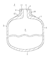
図1はこの発明の実施の形態に係る高圧タンク1を示す。この高圧タンク1は、水素ガス等の35〜75MPaの高圧ガスが充填されるタンク本体2を備え、このタンク本体2は、横断面円形の筒状胴部3の一端に椀状鏡部4を介して横断面円形のガス取出筒部5が一体に突設され、このガス取出筒部5にはガス取出口6が形成されているとともに、上記胴部3の他端には底部7が一体に形成されて構成され、内部に高圧ガスを収容する中空部8を有している。
(Embodiment 1)
FIG. 1 shows a high-
上記タンク本体2は、例えば、JIS A 6061やJIS A 6062等のアルミニウム合金からなる金属製で、成形後にT6処理等の熱処理が施されてなるものであり、筒状ブランク材を塑性変形させて成形され、上記鏡部4、ガス取出筒部5及び底部7は胴部3よりも厚く形成されている。特に、上記鏡部4は、その成形に起因して胴部3からガス取出筒部5に近づくに従って胴部3の厚みからガス取出筒部5の厚みに漸次増大しており、これにより、応力が集中し易い鏡部4を強化している。
The
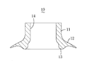
この発明の特徴として、上記タンク本体2のガス取出筒部5から鏡部4にかけての外周には、焼ばめにより金属製の筒状補強カラー10が一体に嵌着されている。この補強カラー10は、図2にも示すように、上記ガス取出筒部5とほぼ厚みが等しい横断面円形の筒部11と、この筒部11の下端に一体に形成されて外側方に張り出した張出部12とからなり、この張出部12の厚みは外端に近づくに従って薄くなっており、これにより、張出部12外端が段差なく鏡部4外表面に沿うようになっている。この補強カラー10は、例えば、SNCM440、SCM440、SKD61等の合金鋼又はチタン合金からなる金属製で、鍛造成形や旋削加工されてなるものであるが、これに限定されず、強度/重量比がアルミニウムよりも高いものであればよく、これによれば、重量軽減に大きく貢献することができる。そして、上記補強カラー10は、その嵌合孔14に上記タンク本体2のガス取出筒部5を挿入した状態でガス取出筒部5に一体に外嵌合され、焼ばめによりタンク本体2のガス取出筒部5から鏡部4にかけての外周に一体に嵌着されている。
As a feature of the present invention, a metal
上述の如くガス取出筒部5及びその近傍の鏡部4の厚みが胴部3に比べて厚くなっているが、補強カラー10を嵌着することで当該箇所の実質的な厚みをさらに増大させることができ、しかも、補強カラー10の素材である合金鋼又はチタン合金等の性質と相俟って当該箇所の強度を一層強固なものにすることができる。したがって、35〜75MPaの高圧に十分に耐え得る高圧タンク1とすることができる。
As described above, the thickness of the gas
また、補強カラー10の装着箇所をタンク本体2全体ではなく、応力が集中し易い鏡部4及びガス取出筒部5に限っているので、高圧タンク1の大幅な重量増加を避けることができて軽量化を図ることができるとともに、加工の簡易化、低価格化を図ることができる。さらに、タンク本体2がアルミニウム合金製で軽量であるため、全体としての重量をさらに軽減することができる。
Further, since the mounting position of the reinforcing
次に、上述の如く構成された高圧タンク1の製造要領の一例を説明する。
Next, an example of the manufacturing procedure of the high-
まず、図3(I)に示すようなアルミニウム合金製の短筒状ブランク材21を用意する。この短筒状ブランク材21は、図示しないが、例えば円柱形のビレットを鍛造成形することにより成形され、筒状胴部31に底部71が一体に形成された有底筒状をしている。別の方法として、円板の板材をダイとポンチとでプレス絞りして有底筒状に成形してもよい。
First, a short cylindrical
そして、上記短筒状ブランク材21をフローフォーミングする。その要領は、図3(II)に示すように、マンドレル15に短筒状ブランク材21を外嵌合して取り付け、上記マンドレル15をその軸心回りに回転させて上記短筒状ブランク材21を一体に回転させ、成形ローラ16を上記短筒状ブランク材21の外周面に圧接させることで回転させながら胴部31を軸心方向にしごくようにする。これにより、短筒状ブランク材21が塑性変形して長筒状ブランク材211が成形される。この段階で、胴部311及び底部711の厚みが、完成品としてのタンク本体2の胴部3及び底部7の厚みと等しくなっている。
And the said short cylindrical
次いで、上記長筒状ブランク材211を図示しないチャック装置で保持してその開口部から所定領域をスピニングにより口絞りする。その要領は、図3(III )に示すように、長筒状ブランク材211をその軸心回りに回転させ、この状態で、成形ローラ17を長筒状ブランク材211の開口部から所定領域に亘って傾けて圧接させることで回転させながら長筒状ブランク材211の軸心に対して斜めに移動させてしごくようにする。これにより、長筒状ブランク材211の開口部から所定領域が塑性変形して筒状胴部3の一端に椀状鏡部4を介してガス取出筒部5が一体に突設されたタンク本体2が成形される。このタンク本体2では、上述の如きスピニングによる口絞り成形により、鏡部4の厚みが胴部3からガス取出筒部5に近づくに従って漸次増大するように成形される。
Next, the long cylindrical
その後、図3(IV)に示すように、別途鍛造成形や旋削加工した合金鋼製又はチタン合金製等の補強カラー10を用意する。この補強カラー10は、上述の如く筒部11の下端に張出部12が一体に形成されているとともに、内部に筒部11及び張出部12を上下に貫通する嵌合孔14が形成されている(図2参照)。上記嵌合孔14の内径は、ガス取出筒部5の外径との関係において焼ばめによる締め代を考慮して設定されている。
Thereafter, as shown in FIG. 3 (IV), a reinforcing
そして、図3(V)に示すように、上記補強カラー10をタンク本体2のガス取出筒部5に外嵌合させ、焼ばめにより上記補強カラー10をタンク本体2のガス取出筒部5から鏡部4にかけての外周に一体に嵌着させる。
Then, as shown in FIG. 3 (V), the reinforcing
このように、別途用意した補強カラー10をタンク本体2のガス取出筒部5に外嵌合させるだけであるため、手間を掛けることなく簡単に高圧タンク1を製造することができる。
In this way, since the separately prepared reinforcing
(実施の形態2)
図4はこの発明の実施の形態2に係る高圧タンク1を示す。この高圧タンク1は、水素ガス等の35〜75MPaの高圧ガスが充填されるタンク本体2を備え、このタンク本体2は、横断面円形の筒状胴部3の一端に椀状鏡部4を介して横断面円形のガス取出筒部5が一体に突設され、このガス取出筒部5にはガス取出口6が形成されているとともに、上記胴部3の他端には底部7が一体に形成されて構成され、内部に高圧ガスを収容する中空部8を有している。
(Embodiment 2)
FIG. 4 shows a high-
上記タンク本体2は、例えば、JIS A 6061やJIS A 6062等のアルミニウム合金からなる金属製で、成形後にT6処理等の熱処理が施されてなるものであり、筒状ブランク材を塑性変形させて成形され、上記鏡部4、ガス取出筒部5及び底部7は胴部3よりも厚く形成されている。特に、上記鏡部4は、その成形に起因して胴部3からガス取出筒部5に近づくに従って胴部3の厚みからガス取出筒部5の厚みに漸次増大しており、これにより、応力が集中し易い鏡部4を強化している。また、この実施の形態2の特徴として、上記鏡部4のガス取出筒部5との境目近傍における外周には、リング状嵌合凹部9が形成されている。
The
この発明の特徴として、上記タンク本体2のガス取出筒部5から鏡部4にかけての外周には、焼ばめにより金属製の筒状補強カラー10が一体に嵌着されている。この補強カラー10は、図5にも示すように、上記ガス取出筒部5とほぼ厚みが等しい横断面円形の筒部11と、この筒部11の下端に一体に形成されて外側方に張り出した張出部12とからなり、この張出部12の厚みは外端に近づくに従って薄くなっており、これにより、張出部12外端が段差なく鏡部4外表面に沿うようになっている。また、この実施の形態2では、上記鏡部4の嵌合凹部9との関係で、上記張出部12の裏面には、リング状膨出部13が一体に下方に膨出して形成され、上記補強カラー10の内部には、上記筒部11及び張出部12を上下に貫通する嵌合孔14が形成されている。この補強カラー10は、例えば、SNCM440、SCM440、SKD61等の合金鋼又はチタン合金からなる金属製で、鍛造成形や旋削加工されてなるものであるが、これに限定されず、強度/重量比がアルミニウムよりも高いものであればよく、これによれば、重量軽減に大きく貢献することができる。そして、上記補強カラー10は、その嵌合孔14に上記タンク本体2のガス取出筒部5を挿入した状態で、上記筒部11がガス取出筒部5に一体に外嵌合されているとともに、上記張出部12がその膨出部13を上記鏡部4の嵌合凹部9に嵌入した状態で焼ばめにより鏡部4外表面に一体に接合されている。
As a feature of the present invention, a metal
上述の如くガス取出筒部5及びその近傍の鏡部4の厚みが胴部3に比べて厚くなっているが、補強カラー10を嵌着することで当該箇所の実質的な厚みをさらに増大させることができ、しかも、補強カラー10の素材である合金鋼又はチタン合金等の性質と相俟って当該箇所の強度を一層強固なものにすることができる。さらには、補強カラー10の膨出部13を鏡部4の嵌合凹部9に嵌入させているので、両者の嵌合状態を確実に行うことができるとともに、上記膨出部13があることで当該箇所の補強カラー10の厚みを増大させてその分だけ強度を向上させることができる。したがって、35〜75MPaの高圧にさらに十分に耐え得る高圧タンク1とすることができる。
As described above, the thickness of the gas
また、補強カラー10の装着箇所をタンク本体2全体ではなく、応力が集中し易い鏡部4及びガス取出筒部5に限っているので、高圧タンク1の大幅な重量増加を避けることができて軽量化を図ることができるとともに、加工の簡易化、低価格化を図ることができる。さらに、タンク本体2がアルミニウム合金製で軽量であるため、全体としての重量をさらに軽減することができる。
Further, since the mounting position of the reinforcing
次に、上述の如く構成された高圧タンク1の製造要領の一例を説明する。
Next, an example of the manufacturing procedure of the high-
まず、図6(I)に示すようなアルミニウム合金製の短筒状ブランク材21を用意する。この短筒状ブランク材21は、図示しないが、例えば円柱形のビレットを鍛造成形することにより成形され、筒状胴部31に底部71が一体に形成された有底筒状をしている。別の方法として、円板の板材をダイとポンチとでプレス絞りして有底筒状に成形してもよい。
First, a short tubular blank 21 made of aluminum alloy as shown in FIG. 6 (I) is prepared. Although not shown, the short cylindrical
そして、上記短筒状ブランク材21をフローフォーミングする。その要領は、図6(II)に示すように、マンドレル15に短筒状ブランク材21を外嵌合して取り付け、上記マンドレル15をその軸心回りに回転させて上記短筒状ブランク材21を一体に回転させ、成形ローラ16を上記短筒状ブランク材21の外周面に圧接させることで回転させながら胴部31を軸心方向にしごくようにする。これにより、短筒状ブランク材21が塑性変形して長筒状ブランク材211が成形される。この段階で、胴部311及び底部711の厚みが、完成品としてのタンク本体2の胴部3及び底部7の厚みと等しくなっている。
And the said short cylindrical
次いで、上記長筒状ブランク材211を図示しないチャック装置で保持してその開口部から所定領域をスピニングにより口絞りする。その要領は、図6(III )に示すように、長筒状ブランク材211をその軸心回りに回転させ、この状態で、成形ローラ17を長筒状ブランク材211の開口部から所定領域に亘って傾けて圧接させることで回転させながら長筒状ブランク材211の軸心に対して斜めに移動させてしごくようにする。これにより、長筒状ブランク材211の開口部から所定領域が塑性変形して筒状胴部3の一端に椀状鏡部4を介してガス取出筒部5が一体に突設されたタンク本体2が成形される。このタンク本体2では、上述の如きスピニングによる口絞り成形により、鏡部4の厚みが胴部3からガス取出筒部5に近づくに従って漸次増大するように成形される。
Next, the long cylindrical
その後、上記タンク本体2を切削装置に搬入し、図6(IV)に示すように、鏡部4のガス取出筒部5との境目近傍における外周にリング状嵌合凹部9を形成する。
Thereafter, the
しかる後、図6(V)に示すように、別途鍛造成形や旋削加工した合金鋼製又はチタン合金製等の補強カラー10を用意する。この補強カラー10は、上述の如く筒部11の下端に張出部12が一体に形成され、張出部12の裏面にはリング状膨出部13が一体に形成されているとともに、内部に筒部11及び張出部12を上下に貫通する嵌合孔14が形成されている(図5参照)。上記嵌合孔14の内径は、ガス取出筒部5の外径との関係において焼ばめによる締め代を考慮して設定されている。
Thereafter, as shown in FIG. 6 (V), a reinforcing
そして、図6(VI)に示すように、上記補強カラー10をタンク本体2のガス取出筒部5に外嵌合させて補強カラー10の膨出部13を鏡部4の嵌合凹部9に嵌入させ、焼ばめにより上記補強カラー10をタンク本体2のガス取出筒部5から鏡部4にかけての外周に一体に嵌着させる。
Then, as shown in FIG. 6 (VI), the reinforcing
このように、別途用意した補強カラー10をタンク本体2のガス取出筒部5に外嵌合させるだけであるため、手間を掛けることなく簡単に高圧タンク1を製造することができる。しかも、両者の嵌合部分において補強カラー10の厚みを増大させてその分だけ強度を向上させることができる。
In this way, since the separately prepared reinforcing
なお、上記の実施の形態1,2では、フローフォーミングに供する短筒状ブランク材21として有底筒状のものを例示したが、両端が開口した円筒体であってもよく、この場合には、両端の開口部から所定領域をスピニングにより口絞りすることになる。
In the first and second embodiments, the short cylindrical
この発明は、軽量でありながら35〜75MPaの高圧ガスに耐え得る高圧タンクとして有用であり、例えば自動車用水素燃料タンク等として利用することができる。 The present invention is useful as a high-pressure tank that can withstand a high-pressure gas of 35 to 75 MPa while being lightweight, and can be used, for example, as a hydrogen fuel tank for automobiles.
1 高圧タンク
2 タンク本体
3 胴部
4 鏡部
5 ガス取出筒部
9 嵌合凹部
10 補強カラー
13 膨出部
21,211 ブランク材
DESCRIPTION OF
Claims (4)
上記ガス取出筒部に外嵌合されて焼ばめによりこのガス取出筒部から鏡部にかけての外周に一体に嵌着された合金鋼又はチタン合金からなる金属製の筒状補強カラーとからなることを特徴とする高圧タンク。 A short cylindrical blank material made of aluminum alloy is plastically deformed, and a gas extraction cylinder part is integrally projected at one end of the cylindrical body part via a bowl-shaped mirror part . The mirror part and the gas extraction cylinder part Is formed thicker than the barrel, and the mirror portion gradually increases from the thickness of the barrel to the thickness of the gas extraction barrel as it approaches the gas extraction barrel from the barrel, and is filled with high-pressure gas of 35 to 75 MPa. A metal tank body,
It is composed of a metal cylindrical reinforcing collar made of alloy steel or titanium alloy that is fitted on the outer periphery from the gas extraction cylinder part to the mirror part by being fitted to the gas extraction cylinder part and fitted by shrink fitting. A high-pressure tank characterized by that.
補強カラーは、ガス取出筒部に嵌着される筒部と、この筒部の一端から外側方に張り出す張出部とからなり、この張出部裏面には、リング状膨出部が膨出して形成され、
一方、鏡部のガス取出筒部との境目近傍における外周には、上記補強カラーを上記ガス取出筒部から鏡部にかけての外周に嵌着した状態で、上記膨出部が嵌入するリング状嵌合凹部が形成されていることを特徴とする高圧タンク。 The high-pressure tank according to claim 1,
The reinforcing collar is composed of a cylinder part fitted to the gas extraction cylinder part and an overhang part projecting outward from one end of the cylinder part, and a ring-like bulge part is inflated on the back surface of the overhang part. Formed out of
On the other hand, on the outer periphery in the vicinity of the boundary between the mirror part and the gas extraction cylinder part, a ring-shaped fitting into which the bulging part is inserted with the reinforcing collar fitted on the outer periphery from the gas extraction cylinder part to the mirror part. A high-pressure tank, wherein a joint recess is formed .
その後、合金鋼又はチタン合金からなる金属製の筒状補強カラーを上記タンク本体のガス取出筒部に外嵌合させて焼ばめにより上記補強カラーをタンク本体のガス取出筒部から鏡部にかけての外周に一体に嵌着させることを特徴とする高圧タンクの製造方法。 A cylindrical blank made of aluminum alloy is plastically deformed while rotating, and a gas extraction cylinder is integrally formed at one end of the cylindrical body via a bowl-shaped mirror. The mirror and the gas extraction The cylindrical portion is formed thicker than the barrel portion, and the mirror portion gradually increases from the thickness of the barrel portion to the thickness of the gas extraction barrel portion as it approaches the gas extraction barrel portion from the barrel portion, and a high pressure gas of 35 to 75 MPa. Molded metal tank body filled with
After that, a metal cylindrical reinforcing collar made of alloy steel or titanium alloy is externally fitted to the gas extracting cylinder part of the tank body, and the reinforcing collar is applied from the gas extracting cylinder part of the tank body to the mirror part by shrink fitting. A method for manufacturing a high-pressure tank, wherein the outer periphery of the high-pressure tank is integrally fitted.
その後、リング状膨出部を有する合金鋼又はチタン合金からなる金属製の筒状補強カラーを上記タンク本体のガス取出筒部に外嵌合させて上記膨出部を鏡部の嵌合凹部に嵌入させ、焼ばめにより上記補強カラーをタンク本体のガス取出筒部から鏡部にかけての外周に一体に嵌着させることを特徴とする高圧タンクの製造方法。 A cylindrical blank made of aluminum alloy is plastically deformed while rotating, and a gas extraction cylinder is integrally formed at one end of the cylindrical body via a bowl-shaped mirror. The mirror and the gas extraction The cylindrical portion is formed thicker than the barrel portion, and the mirror portion gradually increases from the thickness of the barrel portion to the thickness of the gas extraction barrel portion as it approaches the gas extraction barrel portion from the barrel portion, and a high pressure gas of 35 to 75 MPa. After forming a metal tank main body filled with a ring-shaped fitting recess on the outer periphery in the vicinity of the boundary with the gas extraction tube part of the mirror part,
After that, a metal cylindrical reinforcing collar made of alloy steel or titanium alloy having a ring-shaped bulging portion is externally fitted to the gas extraction tube portion of the tank body, and the bulging portion is used as a fitting concave portion of the mirror portion. A method for manufacturing a high-pressure tank, wherein the reinforcing collar is integrally fitted to the outer periphery of the tank body from the gas extraction tube portion to the mirror portion by fitting.
Applications Claiming Priority (1)
| Application Number | Priority Date | Filing Date | Title |
|---|---|---|---|
| US10/600,597 US7137526B2 (en) | 2002-12-02 | 2003-06-23 | High-pressure tank and method for fabricating the same |
Publications (2)
| Publication Number | Publication Date |
|---|---|
| JP2005016707A JP2005016707A (en) | 2005-01-20 |
| JP4029068B2 true JP4029068B2 (en) | 2008-01-09 |
Family
ID=34193421
Family Applications (1)
| Application Number | Title | Priority Date | Filing Date |
|---|---|---|---|
| JP2003354726A Expired - Fee Related JP4029068B2 (en) | 2003-06-23 | 2003-10-15 | High pressure tank and manufacturing method thereof |
Country Status (1)
| Country | Link |
|---|---|
| JP (1) | JP4029068B2 (en) |
Families Citing this family (2)
| Publication number | Priority date | Publication date | Assignee | Title |
|---|---|---|---|---|
| JP5925667B2 (en) * | 2012-11-19 | 2016-05-25 | 株式会社神戸製鋼所 | Aluminum alloy material for high-pressure hydrogen gas container and manufacturing method thereof |
| JP6749629B2 (en) * | 2016-06-01 | 2020-09-02 | サムテック株式会社 | Composite container |
-
2003
- 2003-10-15 JP JP2003354726A patent/JP4029068B2/en not_active Expired - Fee Related
Also Published As
| Publication number | Publication date |
|---|---|
| JP2005016707A (en) | 2005-01-20 |
Similar Documents
| Publication | Publication Date | Title |
|---|---|---|
| US8171769B2 (en) | Method of forming a flanged tubular member in hydroforming | |
| JP3527737B1 (en) | High-pressure tank using high-rigidity fiber and method for manufacturing the same | |
| US20060108783A1 (en) | Structural assembly for vehicles and method of making same | |
| JP2005036918A (en) | High pressure tank using highly rigid fiber and its manufacturing method | |
| EP0740971A1 (en) | Method of manufacturing a bottle-shaped metal container | |
| KR20130116943A (en) | Method for manufacturing hollow engine valve | |
| EP2956253B1 (en) | Multi-stage tube hydroforming process | |
| US20110011896A1 (en) | Steel one-piece necked-in aerosol can | |
| US7143618B2 (en) | Method of making pre-formed tubular members | |
| US6886711B2 (en) | High-pressure tank and method for fabricating the same | |
| US6908006B2 (en) | High-pressure tank and method for fabricating the same | |
| US7137526B2 (en) | High-pressure tank and method for fabricating the same | |
| US7337641B1 (en) | Hydroformed tubular members and method of hydroforming tubular members for vehicles | |
| JP4029068B2 (en) | High pressure tank and manufacturing method thereof | |
| JP2000202552A (en) | Manufacturing method of high pressure gas container liner | |
| US7204114B2 (en) | Method of progressive hydro-forming of tubular members | |
| JP5530168B2 (en) | Pipe member forming method | |
| JP5559591B2 (en) | Manufacturing method for vehicle wheel and vehicle wheel | |
| US6684475B2 (en) | Method of making large volume hollow bodies | |
| US10518817B2 (en) | Method for producing a joint connection between a joint housing and a connection component and suspension component and chassis produced according to the method | |
| US7454942B2 (en) | Hollow molded part with closed cross-section and a reinforcement | |
| US9545657B2 (en) | Method of hydroforming an extruded aluminum tube with a flat nose corner radius | |
| JP2005009673A (en) | Manufacturing method of pressure vessel | |
| US20060225264A1 (en) | Tow hitch receiver | |
| JP2005081432A (en) | Valve housing manufacturing method, and valve manufacturing method |
Legal Events
| Date | Code | Title | Description |
|---|---|---|---|
| A131 | Notification of reasons for refusal |
Free format text: JAPANESE INTERMEDIATE CODE: A131 Effective date: 20061205 |
|
| A521 | Written amendment |
Free format text: JAPANESE INTERMEDIATE CODE: A523 Effective date: 20070222 |
|
| TRDD | Decision of grant or rejection written | ||
| A01 | Written decision to grant a patent or to grant a registration (utility model) |
Free format text: JAPANESE INTERMEDIATE CODE: A01 Effective date: 20071002 |
|
| A61 | First payment of annual fees (during grant procedure) |
Free format text: JAPANESE INTERMEDIATE CODE: A61 Effective date: 20071015 |
|
| FPAY | Renewal fee payment (event date is renewal date of database) |
Free format text: PAYMENT UNTIL: 20101019 Year of fee payment: 3 |
|
| R150 | Certificate of patent or registration of utility model |
Free format text: JAPANESE INTERMEDIATE CODE: R150 |
|
| FPAY | Renewal fee payment (event date is renewal date of database) |
Free format text: PAYMENT UNTIL: 20131019 Year of fee payment: 6 |
|
| R250 | Receipt of annual fees |
Free format text: JAPANESE INTERMEDIATE CODE: R250 |
|
| LAPS | Cancellation because of no payment of annual fees |