JP4029068B2 - 高圧タンク及びその製造方法 - Google Patents
高圧タンク及びその製造方法 Download PDFInfo
- Publication number
- JP4029068B2 JP4029068B2 JP2003354726A JP2003354726A JP4029068B2 JP 4029068 B2 JP4029068 B2 JP 4029068B2 JP 2003354726 A JP2003354726 A JP 2003354726A JP 2003354726 A JP2003354726 A JP 2003354726A JP 4029068 B2 JP4029068 B2 JP 4029068B2
- Authority
- JP
- Japan
- Prior art keywords
- gas extraction
- mirror
- fitted
- cylindrical
- gas
- Prior art date
- Legal status (The legal status is an assumption and is not a legal conclusion. Google has not performed a legal analysis and makes no representation as to the accuracy of the status listed.)
- Expired - Fee Related
Links
- 238000004519 manufacturing process Methods 0.000 title claims description 11
- 238000000605 extraction Methods 0.000 claims description 102
- 230000003014 reinforcing effect Effects 0.000 claims description 58
- 239000000463 material Substances 0.000 claims description 42
- 229910052751 metal Inorganic materials 0.000 claims description 18
- 239000002184 metal Substances 0.000 claims description 18
- 238000000034 method Methods 0.000 claims description 15
- 229910000838 Al alloy Inorganic materials 0.000 claims description 14
- 229910000851 Alloy steel Inorganic materials 0.000 claims description 14
- 229910001069 Ti alloy Inorganic materials 0.000 claims description 14
- 238000013459 approach Methods 0.000 claims description 12
- 239000007789 gas Substances 0.000 description 93
- 230000002787 reinforcement Effects 0.000 description 11
- 238000009987 spinning Methods 0.000 description 10
- 239000012141 concentrate Substances 0.000 description 7
- UFHFLCQGNIYNRP-UHFFFAOYSA-N Hydrogen Chemical compound [H][H] UFHFLCQGNIYNRP-UHFFFAOYSA-N 0.000 description 6
- 238000000465 moulding Methods 0.000 description 5
- 238000010586 diagram Methods 0.000 description 4
- 238000005242 forging Methods 0.000 description 4
- 239000013585 weight reducing agent Substances 0.000 description 4
- VNWKTOKETHGBQD-UHFFFAOYSA-N methane Chemical compound C VNWKTOKETHGBQD-UHFFFAOYSA-N 0.000 description 3
- 229910052782 aluminium Inorganic materials 0.000 description 2
- XAGFODPZIPBFFR-UHFFFAOYSA-N aluminium Chemical compound [Al] XAGFODPZIPBFFR-UHFFFAOYSA-N 0.000 description 2
- 238000010438 heat treatment Methods 0.000 description 2
- 230000002093 peripheral effect Effects 0.000 description 2
- 239000002994 raw material Substances 0.000 description 2
- 238000005728 strengthening Methods 0.000 description 2
- 230000008719 thickening Effects 0.000 description 2
- 238000004804 winding Methods 0.000 description 2
- 229920000049 Carbon (fiber) Polymers 0.000 description 1
- 230000037237 body shape Effects 0.000 description 1
- 239000004917 carbon fiber Substances 0.000 description 1
- 238000005520 cutting process Methods 0.000 description 1
- 238000005516 engineering process Methods 0.000 description 1
- 239000002828 fuel tank Substances 0.000 description 1
- 229910052739 hydrogen Inorganic materials 0.000 description 1
- 239000001257 hydrogen Substances 0.000 description 1
- 239000003345 natural gas Substances 0.000 description 1
- 230000000149 penetrating effect Effects 0.000 description 1
Images


Classifications
-
- F—MECHANICAL ENGINEERING; LIGHTING; HEATING; WEAPONS; BLASTING
- F17—STORING OR DISTRIBUTING GASES OR LIQUIDS
- F17C—VESSELS FOR CONTAINING OR STORING COMPRESSED, LIQUEFIED OR SOLIDIFIED GASES; FIXED-CAPACITY GAS-HOLDERS; FILLING VESSELS WITH, OR DISCHARGING FROM VESSELS, COMPRESSED, LIQUEFIED, OR SOLIDIFIED GASES
- F17C2203/00—Vessel construction, in particular walls or details thereof
- F17C2203/06—Materials for walls or layers thereof; Properties or structures of walls or their materials
- F17C2203/0634—Materials for walls or layers thereof
- F17C2203/0636—Metals
- F17C2203/0646—Aluminium
Landscapes
- Filling Or Discharging Of Gas Storage Vessels (AREA)
Description
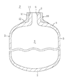
図1はこの発明の実施の形態に係る高圧タンク1を示す。この高圧タンク1は、水素ガス等の35〜75MPaの高圧ガスが充填されるタンク本体2を備え、このタンク本体2は、横断面円形の筒状胴部3の一端に椀状鏡部4を介して横断面円形のガス取出筒部5が一体に突設され、このガス取出筒部5にはガス取出口6が形成されているとともに、上記胴部3の他端には底部7が一体に形成されて構成され、内部に高圧ガスを収容する中空部8を有している。
図4はこの発明の実施の形態2に係る高圧タンク1を示す。この高圧タンク1は、水素ガス等の35〜75MPaの高圧ガスが充填されるタンク本体2を備え、このタンク本体2は、横断面円形の筒状胴部3の一端に椀状鏡部4を介して横断面円形のガス取出筒部5が一体に突設され、このガス取出筒部5にはガス取出口6が形成されているとともに、上記胴部3の他端には底部7が一体に形成されて構成され、内部に高圧ガスを収容する中空部8を有している。
2 タンク本体
3 胴部
4 鏡部
5 ガス取出筒部
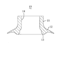
9 嵌合凹部
10 補強カラー
13 膨出部
21,211 ブランク材
Claims (4)
- アルミニウム合金製の短筒状ブランク材を塑性変形させて筒状胴部の一端に椀状鏡部を介してガス取出筒部が一体に突設されて構成され、上記鏡部及びガス取出筒部は上記胴部よりも厚く形成され、かつ上記鏡部は胴部からガス取出筒部に近づくに従って胴部の厚みからガス取出筒部の厚みに漸次増大していて35〜75MPaの高圧ガスが充填される金属製のタンク本体と、
上記ガス取出筒部に外嵌合されて焼ばめによりこのガス取出筒部から鏡部にかけての外周に一体に嵌着された合金鋼又はチタン合金からなる金属製の筒状補強カラーとからなることを特徴とする高圧タンク。 - 請求項1に記載の高圧タンクにおいて、
補強カラーは、ガス取出筒部に嵌着される筒部と、この筒部の一端から外側方に張り出す張出部とからなり、この張出部裏面には、リング状膨出部が膨出して形成され、
一方、鏡部のガス取出筒部との境目近傍における外周には、上記補強カラーを上記ガス取出筒部から鏡部にかけての外周に嵌着した状態で、上記膨出部が嵌入するリング状嵌合凹部が形成されていることを特徴とする高圧タンク。 - アルミニウム合金製の筒状ブランク材を回転させながら塑性変形させて筒状胴部の一端に椀状鏡部を介してガス取出筒部が一体に突設されて構成され、上記鏡部及びガス取出筒部は上記胴部よりも厚く形成され、かつ上記鏡部は胴部からガス取出筒部に近づくに従って胴部の厚みからガス取出筒部の厚みに漸次増大していて35〜75MPaの高圧ガスが充填される金属製のタンク本体を成形し、
その後、合金鋼又はチタン合金からなる金属製の筒状補強カラーを上記タンク本体のガス取出筒部に外嵌合させて焼ばめにより上記補強カラーをタンク本体のガス取出筒部から鏡部にかけての外周に一体に嵌着させることを特徴とする高圧タンクの製造方法。 - アルミニウム合金製の筒状ブランク材を回転させながら塑性変形させて筒状胴部の一端に椀状鏡部を介してガス取出筒部が一体に突設されて構成され、上記鏡部及びガス取出筒部は上記胴部よりも厚く形成され、かつ上記鏡部は胴部からガス取出筒部に近づくに従って胴部の厚みからガス取出筒部の厚みに漸次増大していて35〜75MPaの高圧ガスが充填される金属製のタンク本体を成形した後、上記鏡部のガス取出筒部との境目近傍における外周にリング状嵌合凹部を形成し、
その後、リング状膨出部を有する合金鋼又はチタン合金からなる金属製の筒状補強カラーを上記タンク本体のガス取出筒部に外嵌合させて上記膨出部を鏡部の嵌合凹部に嵌入させ、焼ばめにより上記補強カラーをタンク本体のガス取出筒部から鏡部にかけての外周に一体に嵌着させることを特徴とする高圧タンクの製造方法。
Applications Claiming Priority (1)
| Application Number | Priority Date | Filing Date | Title |
|---|---|---|---|
| US10/600,597 US7137526B2 (en) | 2002-12-02 | 2003-06-23 | High-pressure tank and method for fabricating the same |
Publications (2)
| Publication Number | Publication Date |
|---|---|
| JP2005016707A JP2005016707A (ja) | 2005-01-20 |
| JP4029068B2 true JP4029068B2 (ja) | 2008-01-09 |
Family
ID=34193421
Family Applications (1)
| Application Number | Title | Priority Date | Filing Date |
|---|---|---|---|
| JP2003354726A Expired - Fee Related JP4029068B2 (ja) | 2003-06-23 | 2003-10-15 | 高圧タンク及びその製造方法 |
Country Status (1)
| Country | Link |
|---|---|
| JP (1) | JP4029068B2 (ja) |
Families Citing this family (2)
| Publication number | Priority date | Publication date | Assignee | Title |
|---|---|---|---|---|
| JP5925667B2 (ja) * | 2012-11-19 | 2016-05-25 | 株式会社神戸製鋼所 | 高圧水素ガス容器用アルミニウム合金材とその製造方法 |
| JP6749629B2 (ja) * | 2016-06-01 | 2020-09-02 | サムテック株式会社 | 複合容器 |
-
2003
- 2003-10-15 JP JP2003354726A patent/JP4029068B2/ja not_active Expired - Fee Related
Also Published As
| Publication number | Publication date |
|---|---|
| JP2005016707A (ja) | 2005-01-20 |
Similar Documents
| Publication | Publication Date | Title |
|---|---|---|
| US8171769B2 (en) | Method of forming a flanged tubular member in hydroforming | |
| JP3527737B1 (ja) | 高剛性繊維を用いた高圧タンク及びその製造方法 | |
| US20060108783A1 (en) | Structural assembly for vehicles and method of making same | |
| JP2005036918A (ja) | 高剛性繊維を用いた高圧タンク及びその製造方法 | |
| EP0740971A1 (en) | Method of manufacturing a bottle-shaped metal container | |
| KR20130116943A (ko) | 중공 엔진 밸브의 제조 방법 | |
| EP2956253B1 (en) | Multi-stage tube hydroforming process | |
| US20110011896A1 (en) | Steel one-piece necked-in aerosol can | |
| US7143618B2 (en) | Method of making pre-formed tubular members | |
| US6886711B2 (en) | High-pressure tank and method for fabricating the same | |
| US6908006B2 (en) | High-pressure tank and method for fabricating the same | |
| US7137526B2 (en) | High-pressure tank and method for fabricating the same | |
| US7337641B1 (en) | Hydroformed tubular members and method of hydroforming tubular members for vehicles | |
| JP4029068B2 (ja) | 高圧タンク及びその製造方法 | |
| JP2000202552A (ja) | 高圧ガス容器ライナ―の製造方法 | |
| US7204114B2 (en) | Method of progressive hydro-forming of tubular members | |
| JP5530168B2 (ja) | パイプ部材の成形方法 | |
| JP5559591B2 (ja) | 車両用ホイールの製造方法及び車両用ホイール | |
| US6684475B2 (en) | Method of making large volume hollow bodies | |
| US10518817B2 (en) | Method for producing a joint connection between a joint housing and a connection component and suspension component and chassis produced according to the method | |
| US7454942B2 (en) | Hollow molded part with closed cross-section and a reinforcement | |
| US9545657B2 (en) | Method of hydroforming an extruded aluminum tube with a flat nose corner radius | |
| JP2005009673A (ja) | 圧力容器の製造方法 | |
| US20060225264A1 (en) | Tow hitch receiver | |
| JP2005081432A (ja) | 弁ハウジングの製造方法及び弁の製造方法 |
Legal Events
| Date | Code | Title | Description |
|---|---|---|---|
| A131 | Notification of reasons for refusal |
Free format text: JAPANESE INTERMEDIATE CODE: A131 Effective date: 20061205 |
|
| A521 | Written amendment |
Free format text: JAPANESE INTERMEDIATE CODE: A523 Effective date: 20070222 |
|
| TRDD | Decision of grant or rejection written | ||
| A01 | Written decision to grant a patent or to grant a registration (utility model) |
Free format text: JAPANESE INTERMEDIATE CODE: A01 Effective date: 20071002 |
|
| A61 | First payment of annual fees (during grant procedure) |
Free format text: JAPANESE INTERMEDIATE CODE: A61 Effective date: 20071015 |
|
| FPAY | Renewal fee payment (event date is renewal date of database) |
Free format text: PAYMENT UNTIL: 20101019 Year of fee payment: 3 |
|
| R150 | Certificate of patent or registration of utility model |
Free format text: JAPANESE INTERMEDIATE CODE: R150 |
|
| FPAY | Renewal fee payment (event date is renewal date of database) |
Free format text: PAYMENT UNTIL: 20131019 Year of fee payment: 6 |
|
| R250 | Receipt of annual fees |
Free format text: JAPANESE INTERMEDIATE CODE: R250 |
|
| LAPS | Cancellation because of no payment of annual fees |