JP4028163B2 - Mechanochemical polishing method and mechanochemical polishing apparatus - Google Patents
Mechanochemical polishing method and mechanochemical polishing apparatus Download PDFInfo
- Publication number
- JP4028163B2 JP4028163B2 JP2000259116A JP2000259116A JP4028163B2 JP 4028163 B2 JP4028163 B2 JP 4028163B2 JP 2000259116 A JP2000259116 A JP 2000259116A JP 2000259116 A JP2000259116 A JP 2000259116A JP 4028163 B2 JP4028163 B2 JP 4028163B2
- Authority
- JP
- Japan
- Prior art keywords
- polishing
- cloth
- mechanochemical
- silicon carbide
- abrasive grains
- Prior art date
- Legal status (The legal status is an assumption and is not a legal conclusion. Google has not performed a legal analysis and makes no representation as to the accuracy of the status listed.)
- Expired - Lifetime
Links
- 238000005498 polishing Methods 0.000 title claims description 301
- 238000000034 method Methods 0.000 title claims description 30
- 239000004744 fabric Substances 0.000 claims description 132
- HBMJWWWQQXIZIP-UHFFFAOYSA-N silicon carbide Chemical compound [Si+]#[C-] HBMJWWWQQXIZIP-UHFFFAOYSA-N 0.000 claims description 89
- 229910010271 silicon carbide Inorganic materials 0.000 claims description 89
- 239000006061 abrasive grain Substances 0.000 claims description 72
- WGLPBDUCMAPZCE-UHFFFAOYSA-N Trioxochromium Chemical compound O=[Cr](=O)=O WGLPBDUCMAPZCE-UHFFFAOYSA-N 0.000 claims description 55
- 229910000423 chromium oxide Inorganic materials 0.000 claims description 55
- 239000000843 powder Substances 0.000 claims description 53
- MHAJPDPJQMAIIY-UHFFFAOYSA-N Hydrogen peroxide Chemical compound OO MHAJPDPJQMAIIY-UHFFFAOYSA-N 0.000 claims description 39
- QDOXWKRWXJOMAK-UHFFFAOYSA-N dichromium trioxide Chemical compound O=[Cr]O[Cr]=O QDOXWKRWXJOMAK-UHFFFAOYSA-N 0.000 claims description 31
- 239000011347 resin Substances 0.000 claims description 31
- 229920005989 resin Polymers 0.000 claims description 31
- 239000006260 foam Substances 0.000 claims description 28
- 230000001590 oxidative effect Effects 0.000 claims description 26
- 239000000126 substance Substances 0.000 claims description 26
- 239000000463 material Substances 0.000 claims description 23
- 238000006243 chemical reaction Methods 0.000 claims description 22
- 239000007788 liquid Substances 0.000 claims description 22
- 239000000243 solution Substances 0.000 claims description 22
- 239000000835 fiber Substances 0.000 claims description 21
- 239000007787 solid Substances 0.000 claims description 21
- 230000003197 catalytic effect Effects 0.000 claims description 18
- 239000001301 oxygen Substances 0.000 claims description 18
- 229910052760 oxygen Inorganic materials 0.000 claims description 18
- QVGXLLKOCUKJST-UHFFFAOYSA-N atomic oxygen Chemical compound [O] QVGXLLKOCUKJST-UHFFFAOYSA-N 0.000 claims description 17
- 229920002635 polyurethane Polymers 0.000 claims description 14
- 239000004814 polyurethane Substances 0.000 claims description 14
- 239000011230 binding agent Substances 0.000 claims description 9
- 239000003054 catalyst Substances 0.000 claims description 8
- 238000010438 heat treatment Methods 0.000 claims description 8
- QOSATHPSBFQAML-UHFFFAOYSA-N hydrogen peroxide;hydrate Chemical compound O.OO QOSATHPSBFQAML-UHFFFAOYSA-N 0.000 claims description 8
- 229920005830 Polyurethane Foam Polymers 0.000 claims description 7
- 239000011496 polyurethane foam Substances 0.000 claims description 7
- 239000000025 natural resin Substances 0.000 claims description 6
- 229920003002 synthetic resin Polymers 0.000 claims description 6
- 239000000057 synthetic resin Substances 0.000 claims description 6
- 238000003825 pressing Methods 0.000 claims description 4
- 239000003365 glass fiber Substances 0.000 claims description 3
- 239000000758 substrate Substances 0.000 claims description 3
- 239000012209 synthetic fiber Substances 0.000 claims description 3
- 229920002994 synthetic fiber Polymers 0.000 claims description 3
- 230000001678 irradiating effect Effects 0.000 claims description 2
- 238000002347 injection Methods 0.000 claims 1
- 239000007924 injection Substances 0.000 claims 1
- 235000012431 wafers Nutrition 0.000 description 71
- 230000003746 surface roughness Effects 0.000 description 26
- 238000010586 diagram Methods 0.000 description 23
- 239000010410 layer Substances 0.000 description 23
- 239000007800 oxidant agent Substances 0.000 description 21
- 239000013078 crystal Substances 0.000 description 20
- 239000007789 gas Substances 0.000 description 15
- NUJOXMJBOLGQSY-UHFFFAOYSA-N manganese dioxide Chemical compound O=[Mn]=O NUJOXMJBOLGQSY-UHFFFAOYSA-N 0.000 description 14
- 239000010408 film Substances 0.000 description 13
- MYMOFIZGZYHOMD-UHFFFAOYSA-N Dioxygen Chemical compound O=O MYMOFIZGZYHOMD-UHFFFAOYSA-N 0.000 description 10
- 230000008859 change Effects 0.000 description 10
- 229910001882 dioxygen Inorganic materials 0.000 description 10
- 239000002245 particle Substances 0.000 description 10
- 238000002474 experimental method Methods 0.000 description 7
- 238000000227 grinding Methods 0.000 description 7
- 239000004065 semiconductor Substances 0.000 description 7
- 230000002123 temporal effect Effects 0.000 description 7
- 239000012298 atmosphere Substances 0.000 description 6
- 229910003460 diamond Inorganic materials 0.000 description 6
- 239000010432 diamond Substances 0.000 description 6
- 230000008569 process Effects 0.000 description 6
- XLYOFNOQVPJJNP-UHFFFAOYSA-N water Substances O XLYOFNOQVPJJNP-UHFFFAOYSA-N 0.000 description 6
- 239000004745 nonwoven fabric Substances 0.000 description 5
- VYPSYNLAJGMNEJ-UHFFFAOYSA-N Silicium dioxide Chemical compound O=[Si]=O VYPSYNLAJGMNEJ-UHFFFAOYSA-N 0.000 description 4
- 229910010413 TiO 2 Inorganic materials 0.000 description 4
- GWEVSGVZZGPLCZ-UHFFFAOYSA-N Titan oxide Chemical compound O=[Ti]=O GWEVSGVZZGPLCZ-UHFFFAOYSA-N 0.000 description 4
- 230000007547 defect Effects 0.000 description 4
- 238000002156 mixing Methods 0.000 description 4
- 239000000203 mixture Substances 0.000 description 4
- 238000007517 polishing process Methods 0.000 description 4
- 238000003746 solid phase reaction Methods 0.000 description 4
- 239000007795 chemical reaction product Substances 0.000 description 3
- 239000011572 manganese Substances 0.000 description 3
- 229910052751 metal Inorganic materials 0.000 description 3
- 239000002184 metal Substances 0.000 description 3
- 238000007254 oxidation reaction Methods 0.000 description 3
- WUPHOULIZUERAE-UHFFFAOYSA-N 3-(oxolan-2-yl)propanoic acid Chemical compound OC(=O)CCC1CCCO1 WUPHOULIZUERAE-UHFFFAOYSA-N 0.000 description 2
- KRHYYFGTRYWZRS-UHFFFAOYSA-N Fluorane Chemical compound F KRHYYFGTRYWZRS-UHFFFAOYSA-N 0.000 description 2
- XUIMIQQOPSSXEZ-UHFFFAOYSA-N Silicon Chemical compound [Si] XUIMIQQOPSSXEZ-UHFFFAOYSA-N 0.000 description 2
- MCMNRKCIXSYSNV-UHFFFAOYSA-N Zirconium dioxide Chemical compound O=[Zr]=O MCMNRKCIXSYSNV-UHFFFAOYSA-N 0.000 description 2
- 230000009471 action Effects 0.000 description 2
- 239000000853 adhesive Substances 0.000 description 2
- 230000001070 adhesive effect Effects 0.000 description 2
- 229910052980 cadmium sulfide Inorganic materials 0.000 description 2
- 230000015556 catabolic process Effects 0.000 description 2
- 239000000919 ceramic Substances 0.000 description 2
- 239000011651 chromium Substances 0.000 description 2
- 230000000694 effects Effects 0.000 description 2
- 239000012634 fragment Substances 0.000 description 2
- 239000012535 impurity Substances 0.000 description 2
- 230000014759 maintenance of location Effects 0.000 description 2
- 230000003647 oxidation Effects 0.000 description 2
- 239000011148 porous material Substances 0.000 description 2
- 230000001737 promoting effect Effects 0.000 description 2
- 229910052710 silicon Inorganic materials 0.000 description 2
- 239000010703 silicon Substances 0.000 description 2
- 239000000377 silicon dioxide Substances 0.000 description 2
- 235000012239 silicon dioxide Nutrition 0.000 description 2
- 239000002344 surface layer Substances 0.000 description 2
- PNEYBMLMFCGWSK-UHFFFAOYSA-N Alumina Chemical compound [O-2].[O-2].[O-2].[Al+3].[Al+3] PNEYBMLMFCGWSK-UHFFFAOYSA-N 0.000 description 1
- RYGMFSIKBFXOCR-UHFFFAOYSA-N Copper Chemical compound [Cu] RYGMFSIKBFXOCR-UHFFFAOYSA-N 0.000 description 1
- KWYUFKZDYYNOTN-UHFFFAOYSA-M Potassium hydroxide Chemical compound [OH-].[K+] KWYUFKZDYYNOTN-UHFFFAOYSA-M 0.000 description 1
- 229910004298 SiO 2 Inorganic materials 0.000 description 1
- ATJFFYVFTNAWJD-UHFFFAOYSA-N Tin Chemical compound [Sn] ATJFFYVFTNAWJD-UHFFFAOYSA-N 0.000 description 1
- 229910052782 aluminium Inorganic materials 0.000 description 1
- XAGFODPZIPBFFR-UHFFFAOYSA-N aluminium Chemical compound [Al] XAGFODPZIPBFFR-UHFFFAOYSA-N 0.000 description 1
- 230000015572 biosynthetic process Effects 0.000 description 1
- 238000004140 cleaning Methods 0.000 description 1
- 150000001875 compounds Chemical class 0.000 description 1
- 229910052802 copper Inorganic materials 0.000 description 1
- 239000010949 copper Substances 0.000 description 1
- 239000006185 dispersion Substances 0.000 description 1
- 239000002612 dispersion medium Substances 0.000 description 1
- 238000001312 dry etching Methods 0.000 description 1
- 238000005530 etching Methods 0.000 description 1
- 238000009499 grossing Methods 0.000 description 1
- 230000017525 heat dissipation Effects 0.000 description 1
- PJXISJQVUVHSOJ-UHFFFAOYSA-N indium(iii) oxide Chemical compound [O-2].[O-2].[O-2].[In+3].[In+3] PJXISJQVUVHSOJ-UHFFFAOYSA-N 0.000 description 1
- GEYXPJBPASPPLI-UHFFFAOYSA-N manganese(iii) oxide Chemical compound O=[Mn]O[Mn]=O GEYXPJBPASPPLI-UHFFFAOYSA-N 0.000 description 1
- 230000007246 mechanism Effects 0.000 description 1
- 239000008155 medical solution Substances 0.000 description 1
- 230000003287 optical effect Effects 0.000 description 1
- 150000002926 oxygen Chemical class 0.000 description 1
- 230000035515 penetration Effects 0.000 description 1
- 230000035699 permeability Effects 0.000 description 1
- 230000000704 physical effect Effects 0.000 description 1
- 229920006267 polyester film Polymers 0.000 description 1
- 238000003672 processing method Methods 0.000 description 1
- 238000001953 recrystallisation Methods 0.000 description 1
- 230000009467 reduction Effects 0.000 description 1
- 229910052594 sapphire Inorganic materials 0.000 description 1
- 239000010980 sapphire Substances 0.000 description 1
- 238000006748 scratching Methods 0.000 description 1
- 230000002393 scratching effect Effects 0.000 description 1
- -1 specifically Chemical compound 0.000 description 1
- 239000007921 spray Substances 0.000 description 1
- 229910001220 stainless steel Inorganic materials 0.000 description 1
- 239000010935 stainless steel Substances 0.000 description 1
- 238000000859 sublimation Methods 0.000 description 1
- 230000008022 sublimation Effects 0.000 description 1
- 239000010409 thin film Substances 0.000 description 1
- 239000004408 titanium dioxide Substances 0.000 description 1
- 238000011144 upstream manufacturing Methods 0.000 description 1
- 238000012795 verification Methods 0.000 description 1
- 238000001039 wet etching Methods 0.000 description 1
Images


Classifications
-
- C—CHEMISTRY; METALLURGY
- C09—DYES; PAINTS; POLISHES; NATURAL RESINS; ADHESIVES; COMPOSITIONS NOT OTHERWISE PROVIDED FOR; APPLICATIONS OF MATERIALS NOT OTHERWISE PROVIDED FOR
- C09K—MATERIALS FOR MISCELLANEOUS APPLICATIONS, NOT PROVIDED FOR ELSEWHERE
- C09K3/00—Materials not provided for elsewhere
- C09K3/14—Anti-slip materials; Abrasives
- C09K3/1454—Abrasive powders, suspensions and pastes for polishing
- C09K3/1463—Aqueous liquid suspensions
-
- B—PERFORMING OPERATIONS; TRANSPORTING
- B24—GRINDING; POLISHING
- B24B—MACHINES, DEVICES, OR PROCESSES FOR GRINDING OR POLISHING; DRESSING OR CONDITIONING OF ABRADING SURFACES; FEEDING OF GRINDING, POLISHING, OR LAPPING AGENTS
- B24B37/00—Lapping machines or devices; Accessories
- B24B37/04—Lapping machines or devices; Accessories designed for working plane surfaces
- B24B37/042—Lapping machines or devices; Accessories designed for working plane surfaces operating processes therefor
- B24B37/044—Lapping machines or devices; Accessories designed for working plane surfaces operating processes therefor characterised by the composition of the lapping agent
-
- C—CHEMISTRY; METALLURGY
- C09—DYES; PAINTS; POLISHES; NATURAL RESINS; ADHESIVES; COMPOSITIONS NOT OTHERWISE PROVIDED FOR; APPLICATIONS OF MATERIALS NOT OTHERWISE PROVIDED FOR
- C09G—POLISHING COMPOSITIONS; SKI WAXES
- C09G1/00—Polishing compositions
- C09G1/02—Polishing compositions containing abrasives or grinding agents
-
- H—ELECTRICITY
- H01—ELECTRIC ELEMENTS
- H01L—SEMICONDUCTOR DEVICES NOT COVERED BY CLASS H10
- H01L21/00—Processes or apparatus adapted for the manufacture or treatment of semiconductor or solid state devices or of parts thereof
- H01L21/02—Manufacture or treatment of semiconductor devices or of parts thereof
- H01L21/04—Manufacture or treatment of semiconductor devices or of parts thereof the devices having potential barriers, e.g. a PN junction, depletion layer or carrier concentration layer
- H01L21/0445—Manufacture or treatment of semiconductor devices or of parts thereof the devices having potential barriers, e.g. a PN junction, depletion layer or carrier concentration layer the devices having semiconductor bodies comprising crystalline silicon carbide
- H01L21/0475—Changing the shape of the semiconductor body, e.g. forming recesses
Landscapes
- Engineering & Computer Science (AREA)
- Chemical & Material Sciences (AREA)
- Organic Chemistry (AREA)
- Physics & Mathematics (AREA)
- Mechanical Engineering (AREA)
- Crystallography & Structural Chemistry (AREA)
- Materials Engineering (AREA)
- Condensed Matter Physics & Semiconductors (AREA)
- General Physics & Mathematics (AREA)
- Manufacturing & Machinery (AREA)
- Computer Hardware Design (AREA)
- Microelectronics & Electronic Packaging (AREA)
- Power Engineering (AREA)
- Mechanical Treatment Of Semiconductor (AREA)
- Finish Polishing, Edge Sharpening, And Grinding By Specific Grinding Devices (AREA)
Description
【0001】
【発明の属する技術分野】
この発明はメカノケミカル研磨に係り、詳しくは、酸化クロム(III) つまりCr2 O3 を砥粒として用いた研磨技術に関するものである。
【0002】
【従来の技術】
シリコン(以後、Siと記す)よりも大きな物性値を持つ炭化珪素(以後、SiCと記す)に形成したパワー半導体素子は、Siのパワー半導体素子よりも優れた性能を実現できる。詳しくは、広いエネルギーギャップ(Siに対して、約3倍)によって、高温まで半導体として機能できること、高い絶縁破壊耐圧(10倍)によって、高耐圧化が可能なこと、高い熱伝導率(約3倍)によって、放熱性に優れ、さらなる大電流化が図れることがあげられる。具体的には、例えば図22に示すように、素子を形成するSiCウェハは、高不純物濃度の単結晶SiC基板100上に、低不純物濃度のSiC層101がエピタキシャル成長で形成されたウェハが使用される。この低濃度層101に縦方向に電流を流すタイプの素子(例えば、VDMOS)103が形成される。また、光デバイスの分野では、短波長の発光が可能な材料としてGaNが研究されているが、SiCはサファイアに比べてGaNとの格子不整合が小さいために、SiCウェハはGaN薄膜を形成する下地基板としても注目されている。
【0003】
SiCウェハは、SiC粉末を昇華して種結晶に再結晶化で成長させたバルク単結晶SiCを、切断してウェハ形状にした後、その表面(切断面)を鏡面加工する。この面にSiC層、あるいはGaN層をエピタキシャル成長させるが、結晶性の良いエピタキシャル層を得るためには、無欠陥で、しかも原子レベルで平滑な面であることが要求される。
【0004】
SiCの鏡面加工は、ダイヤモンド砥粒で表面を研磨して平滑化する方法が一般的である。これは、SiC(被研磨材料)よりも硬い材料の砥粒(ダイヤモンド)を使って表面を削る機械的な表面加工方法である。ここで、砥粒径を小さくするほど、表面は平滑になる(面粗度が向上する)が、加工による欠陥(加工変質層)の発生を抑止することはできない。従って、研磨後にドライエッチングする、または熱酸化で酸化膜を成長させた後にフッ酸でウェットエッチングするなどの加工変質層を除去する工程を研磨の後工程として行わなければならないといった問題があった。
【0005】
また、ダイヤモンド砥粒は高価であり、粒径が小さくなるほど、さらに高価になる。さらに、微小な砥粒の中に大きな砥粒が混入していると、面粗度が向上しない、またはひっかき傷が発生して深い欠陥が局所的に発生することがあるため、粒径のそろった高品質なダイヤモンド砥粒を使用しなけらばならず、やはりこの点でも砥粒は高価になる。また、工程管理(砥粒径の管理)も難しくなる。このようにダイヤモンド砥粒を使った研磨には問題があった。
【0006】
被研磨材料よりも硬度が小さい材料を砥粒とした研磨ならば、加工面にダメージの少ない加工ができるが、直接砥粒が被研磨材料を削る機械的な加工はできない。被研磨材料の表面に機械的に脆い反応生成物(酸化物、化合物など)を形成して、これを軟質砥粒で剥ぎ取る研磨方法、いわゆるメカノケミカル研磨(化学的機械研磨;MCP)ができればよい。しかし、SiCは化学的に安定な材料であるために、反応生成物の形成が困難である。
【0007】
SiCのメカノケミカル研磨の方法については、酸化クロムを砥粒としてSiCを研磨する方法が報告されている(M.Kikuchi,Y.Takahashi,T Suga,S Suzuki,and Y Bando,“Mechanochemical Polishing of Silicon Carbide Single Crystal with Chromium(III) Oxide Abrasive ”,J.Am.Ceram.Soc.,75[1](1992)189)。これによると、酸化クロム砥粒を樹脂で固めたディスク(固定砥粒)上でSiCをドライポリッシュすることで、残留歪み、ひっかき傷のない研磨(MCP)が実現できることが報告されている。
【0008】
また、特開平7−80770号公報では、遊離砥粒の酸化クロム粉末とポリシング定盤の硬度がマイクロビッカース硬さで1000〜2000の材料を使用することで、SiCの表面平坦度を良くする方法が提案されている。これらの方法は、被研磨材料と砥粒の接触点におけるメカノケミカル現象で、両者の直接的な固相反応で生じた反応層を砥粒の摩擦作用により除去する研磨方法である。
【0009】
この固相反応を利用した研磨方法は、特公昭56−23746号公報で提案された方法であり、前述の“Mechanochemical Polishing of Silicon Carbide Single Crystal with Chromium(III) Oxide Abrasive ”と特開平7−80770号公報は、被研磨材料がSiC、砥粒が酸化クロムの組み合わせで行われたものである。
【0010】
【発明が解決しようとする課題】
しかしながら、固相反応を生じさせるためには、被研磨材料と砥粒の接点において、きわめて高圧で両者を接触させることが重要であると推察される。加工圧力は、前述の“Mechanochemical Polishing of Silicon Carbide Single Crystal with Chromium(III) Oxide Abrasive ”では0.34MPa(3.5kgf/cm2 )、特開平7−80770号公報では、900kgf/cm2 で実験をしている。高い加工圧力が必要になると、大口径のウェハを研磨するときには、ポリシング定盤にきわめて高い圧力がかかることになる。また、同じポリシング定盤上で複数のウェハを同時に研磨する場合については、さらに高圧がかかることになる。従って、研磨装置には従来にない高い剛性が必要となるといった問題があった。
【0011】
また、加工圧力は、砥粒との接触点であるウェハ表面だけでなくSiCウェハ全体に加わることになり、結晶歪や欠陥の発生、既存の欠陥の進行、さらには不均一に力が加わった場合にはウェハが割れるといった問題が生じる。しかし、低い加工圧力では固相反応が起こらない、また反応が生じてもその速度、すなわち研磨速度が遅くなり、研磨時間が長くなるといった問題があった。
【0012】
この発明はこのような背景の元になされたものであり、その目的は、SiCなどの硬質材料を低い加工圧力でも効率よく研磨することができるメカノケミカル研磨方法及びメカノケミカル研磨装置を提供することにある。
【0013】
【課題を解決するための手段】
本発明のメカノケミカル研磨方法によれば、酸化クロム(III)の粉末を砥粒として用いて被研磨材である炭化珪素(SiC)ウェハの研磨を行う際に、研磨面に酸化剤が存在する。この酸化剤により、研磨能率が促進される。
【0014】
これは、次の理由によると推測される。酸化クロム砥粒の作用に関して、酸化クロム砥粒は本来、SiCの表面に酸化物を形成する触媒として機能しているが、研磨面に配した酸化剤によりSiCと反応する酸素が増加して反応効率が向上し、それ故、研磨能率の促進が図られるものと考えられる。
【0015】
このようにして、SiCなどの硬質材料を低い加工圧力でも効率よく研磨することができる。そして、SiCウェハに対し相対運動する部材の表面に配された研磨布上に、酸化性の薬液として過酸化水素水を供給し、該研磨布上にSiCウェハを0.0098〜0.294MPa(0.1〜3.0kgf/cm2)の加工圧力で押し付けながら研磨を行うようにしている。
【0016】
さらに、酸化剤の供給方法として、請求項2に記載のように、酸化性の薬液として過酸化水素水を、滴下によって研磨面に供給することができる。
【0017】
また、請求項3に記載のように、酸化クロム粉末以外の化学反応の触媒作用のある固体粉末を、滴下する液に分散させて研磨面に供給したり、請求項4に記載のように、酸化クロム粉末以外の化学反応の触媒作用のある固体粉末を、SiCウェハに対し相対運動する部材側に配することにより研磨面に供給すると、化学反応を促進させることができる。
【0019】
さらに、請求項5に記載のように、化学反応の触媒作用のある固体粉末に対し光を照射すると、触媒作用を向上させることができる。また、請求項6に記載のように、SiCウェハを加熱しながらSiCウェハの研磨を行うと、研磨能率を向上させることができる。
【0021】
また、メカノケミカル研磨装置として、請求項7に記載のように、SiCウェハに対し相対運動する部材の表面に研磨布を配するとともに、研磨面に酸化性の薬液として前記酸化クロム(III)の砥粒が分散した過酸化水素水を供給するための注液器を設け、前記研磨布上に前記酸化クロム(III)の砥粒が分散した過酸化水素水を滴下しながら、前記研磨布に前記SiCウェハを0.0098〜0.294MPa(0.1〜3.0kgf/cm2)の加工圧力で押し付けて研磨することによって、前記酸化クロム(III)の砥粒を前記SiCウェハの表面に酸化物を形成する触媒として機能させつつ、前記研磨面に配した過酸化水素水により前記SiCウェハと反応する酸素を増加させて研磨することにより、より好ましいものとなる。
【0022】
さらに、請求項8に記載のように、少なくとも研磨面を加熱する加熱手段を設けたり、請求項9に記載のように、酸化クロム粉末以外の化学反応の触媒作用のある固体粉末を分散した液を研磨面に供給するための注液器を設けたり、請求項10に記載のように、SiCウェハに対し相対運動する部材に、酸化クロム粉末以外の化学反応の触媒作用のある固体粉末を配すると、好ましいものとなる。ここで、請求項11に記載のように、化学反応の触媒作用のある固体粉末に対し光を照射する光源を設けるとよい。
【0024】
請求項12に記載のように、研磨布として、表面に対して垂直方向に連続した孔または空隙が形成された構造体を使うと、研磨布表面から深さ方向への浸透性がよくなり、SiCウェハのかけらなどの排出が容易になることで、キズ、クラック、結晶歪みのない良好な研磨面の形成が可能になる。
【0025】
ここで、請求項13に記載のように、研磨布として、合成繊維、ガラス繊維、天然繊維、合成樹脂、天然樹脂の少なくともいずれかより成る構造体を使うとよい。
【0026】
特に、請求項14に記載のように、ポリウレタン材料で垂直発泡体構造のスウェードタイプの研磨布や請求項15に記載のように、繊維の交絡体中に樹脂を含浸することで樹脂が繊維の結合材として働く、あるいは、樹脂層自体が連続発泡体構造になっている不織布タイプの研磨布や請求項16に記載のように、繊維の交絡体中に樹脂を含浸することで樹脂が繊維の結合材として働く、あるいは、樹脂層自体が連続発泡体構造になっている不織布タイプの布を下地層として、これに、ポリウレタン材料で、垂直発泡体構造のスウェードタイプの布を、貼り合わせた2層構造の研磨布が適している。
【0027】
請求項17に記載のように、研磨布として、表面と内部に独立した孔または気泡が形成された構造体にすることで、研磨布は硬質で、かつ表面の砥粒、薬液の保持性がよくなり、凹凸のあるSiCウェハの表面を短時間で平坦化・平滑化することができる。また、研磨の前工程(研削工程、ラッピング工程など)で発生した加工変質層を短時間に除去することもできる。
【0028】
ここで、請求項18に記載のように、研磨布として、合成樹脂または天然樹脂からなる構造体を使うとよい。特に、請求項19に記載のように、独立発泡体構造の発泡ポリウレタンタイプの研磨布が適している。
【0029】
請求項20に記載のように、研磨布として、表面に対して垂直方向に連続した孔または空隙が形成された構造体の布を下地層として、これに、表面と内部に独立した孔または気泡が形成された構造体の布を、貼り合わせた2層構造の研磨布を使うことで、表層側の構造体(ウェハと接する布)によって、研磨速度と平坦化効率が優れ、また、下地層の構造体(下地用布)によって、SiCウェハのうねり、反りに対する追従性が向上することで、ウェハを精度よく研磨することができる。
【0030】
特に、請求項21に記載のように、研磨布として、繊維の交絡体中に樹脂を含浸することで樹脂が繊維の結合材として働く、あるいは、樹脂層自体が連続発泡体構造になっている不織布タイプの布を下地層として、これに、独立発泡体構造の発泡ポリウレタンタイプの布を、貼り合わせた2層構造の研磨布が適している。
【0031】
【発明の実施の形態】
(第1の実施の形態)
以下、この発明を具体化した第1の実施の形態を図面に従って説明する。
【0032】
図1には、本実施の形態におけるメカノケミカル研磨装置の概略構成図を示す。
研磨定盤1には研磨布2が貼り付けられている。この研磨布2には、発泡ポリウレタン、不織布、フェルト、スウェード等が使用される。研磨定盤1の上方においてウェハ保持用テーブル3が配置され、ウェハ保持用テーブル3にSiCウェハ4を保持することができるようになっている。また、加工の際には、ウェハ保持用テーブル3が研磨布2に向かって押し付けられ、SiCウェハ4における研磨する面が所定の加工圧力で押し付けられる。
【0033】
また、ウェハ保持用テーブル3および研磨定盤1は回転することができる。
さらに、研磨定盤1の上方において注液器(ノズル)5が設置され、この注液器5から薬液6が研磨布2上に滴下される。この薬液6は、過酸化水素水(酸化性薬液)に酸化クロム(III) の砥粒を分散させたものである。つまり、酸化クロム砥粒と酸化性の薬液を混合して用いている。
【0034】
このように、酸化クロム(III) の粉末を砥粒として用い、被研磨材である単結晶SiCウェハ(半導体ウェハ)4を研磨布2に押し付けながら研磨を行う際に、研磨布2の上に注液器5から酸化性の薬液である過酸化水素水を滴下して過酸化水素水を研磨面に供給する機構となっている。これにより、研磨面に過酸化水素水(酸化剤)が存在する状態で研磨を行うことができる。
【0035】
なお、ウェハ保持用テーブル3を研磨定盤1に対して揺動させると、ウェハ面内の加工精度が向上するとともに、研磨布の寿命も向上させることができる。
次に、メカノケミカル研磨方法について説明する。
【0036】
まず、ウェハ保持用テーブル3にSiCウェハ4を保持する。そして、研磨する面を研磨定盤1に貼り付けられた研磨布2に所定の加工圧力で押し付ける。さらに、ウェハ保持用テーブル3と研磨定盤1を回転させ、研磨布2上に薬液(酸化クロム砥粒が分散した過酸化水素水)6を滴下しながら研磨する。
【0037】
この研磨を行う際に研磨面に過酸化水素水(酸化剤)が存在し、この過酸化水素水により研磨能率が促進される。これは、酸化クロム砥粒はSiCの表面に酸化物を形成する触媒として機能し、研磨面に配した過酸化水素水によりSiCと反応する酸素が増加して反応効率が向上し、研磨能率の促進が図られるものと考えられる。このようにして、SiCなどの硬質材料を低い加工圧力でも効率よく研磨することができる。
【0038】
ここで、研磨可能な最低圧力は、研磨布2の種類、酸化クロム砥粒の濃度や粒径、過酸化水素水の濃度や滴下量、さらにはウェハ保持用テーブル3と研磨定盤1の回転数などによって決まる。
【0039】
本発明者の実験では、低い加工圧力(0.34kgf/cm2 )でも30分の研磨で、1.20nm(中心線平均あらさRa)の面粗度を0.43nmに平滑化することができた。このときの研磨条件は、発泡ポリウレタンの研磨布、過酸化水素水(濃度10%)に、0.5μm(粒径)の酸化クロム砥粒(濃度10wt%)を分散させた研磨液(滴下量5.0ミリリットル/分)、及びウェハ保持用テーブルの回転数40rpm,研磨定盤の回転数40rpmの条件で行った。
【0040】
詳しい実験結果を図2〜9を用いて説明する。
実験は次のようにして行った。試料として、単結晶SiC(6H−SiC)を用い、このSiCウェハの(0001)Si面を研磨した。研磨条件は、(i) 本実施形態で説明した過酸化水素水(酸化剤)を滴下しながらのポリッシュと、比較のために、(ii)ドライポリッシュおよび(iii) ウェットポリッシュの三通りである。詳しくは、(i) の過酸化水素水を滴下しながらのポリッシュについては、酸化クロム砥粒(10wt%)を過酸化水素水(濃度10%)に分散させた液を研磨布に滴下して研磨した。(ii)のドライポリッシュについては、酸化クロム砥粒を塗布した研磨布で研磨した。(iii) のウェットポリッシュについては、酸化クロム砥粒を10wt%で水に分散させた酸化クロム液を研磨布に滴下して研磨した。
【0041】
研磨の評価は、面粗度の時間的変化で行った。つまり、各試料の面粗度の変化を調べた。
また、研磨布は発泡ポリウレタン、酸化クロムは粒径0.5μmの砥粒を用いた。加工圧力は3.0kgf/cm2 である。研磨前の表面は、研削(#8000)で加工した面であり、一定方向にダイヤモンドの砥石が削った凹凸(研削条痕)があった。
【0042】
図2には、前述のドライポリッシュを10分間行った後の表面状態を示す。このときの面粗度Raは1.11nmであった。同様に、図3には、ドライポリッシュを20分間行った後の表面状態を示す。このときの面粗度Raは0.80nmであった。また、図4には、前述のウェットポリッシュを10分間行った後の表面状態を示す。このときの面粗度Raは1.15nmであった。同様に、図5には、ウェットポリッシュを20分間行った後の表面状態を示す。このときの面粗度Raは0.92nmであった。さらに、図6には、前述の過酸化水素水(酸化剤)を滴下しながらのポリッシュを10分間行った後の表面状態を示す。このときの面粗度Raは0.73nmであった。同様に、図7には、過酸化水素水(酸化剤)を滴下しながらのポリッシュを20分間行った後の表面状態を示す。このときの面粗度Raは0.57nmであった。
【0043】
このようにして得られたデータをまとめたものを図8に示す。図8の横軸には研磨時間をとり、縦軸には面粗度をとっている。この面粗度の変化を示す図から、酸化剤を混合した条件(試料)が短い研磨時間で面粗度が向上していることが分かる。また、20分の加工をした段階では、酸化剤を混合した場合のみ、研削条痕が消滅していた。このように、酸化剤を混合することによって、研磨促進の効果が確認できた。
【0044】
さらに、加工圧力を下げて同様の実験を行った(加工圧力以外はすべて同じ条件で研磨を行った)。具体的には、これまでは3.0kgf/cm2 であったが、0.6kgf/cm2 に下げて、ウェットポリッシュ(酸化クロム砥粒を水に10wt%で分散)と酸化剤混合のポリッシュ(酸化クロム砥粒を過酸化水素水(10%)に10wt%で分散)を行った。図9にはその実験結果(面粗度の変化)を示す。
【0045】
この図9と前述の図8とを比較すると、ウェットポリッシュと酸化剤混合のポリッシュとでは加工圧力が低くなると、過酸化水素の有無で研磨能率の差が顕著になることが分かる。つまり、例えば、40分間の研磨を行ったときで比較すると、ウェットポリッシュでは加工圧力3.0kgf/cm2 の実験(図8)ではRa≒0.6nmであるとともに加工圧力0.6kgf/cm2 の実験(図9)ではRa≒1.2nmであるのに対し、酸化剤混合のポリッシュでは図8ではRa≒0.6nmであるとともに図9でもRa≒0.6nmであり、ウェットポリッシュ(水に分散)では加工圧力が下がると研磨能率は大幅に低下するが、酸化剤として過酸化水素を混合したポリッシュについては研磨能率の低下が小さいことが分かる。
【0046】
また、データの図示は行わないが、酸化剤混合のポリッシュ条件で、さらに加工圧力を低く(0.34kgf/cm2 )して実験を行ったが、30分の研磨時間で面粗度はRaが1.20nmから0.43nmまで低減した。
【0047】
このようなことから、酸化剤として過酸化水素を混合することで、加工圧力を低くしても研磨能率の低下は小さいことが分かる。
以上のような考察および実験結果から、酸化クロム(Cr2 O3 )を砥粒にして研磨する際に、酸化クロム砥粒と酸化剤を混合することによって、低い加工圧力で、容易に、効率よくSiCウェハを研磨することができる。より好ましくは、ウェハを研磨する加工圧力を、0.0098〜0.294MPa(0.1〜3.0kgf/cm2 )とするとよい。
【0048】
なお、酸化クロムが同量ならば、酸化クロムの砥粒径が小さくなるほど、その表面積が大きくなるために研磨能率は向上し、面粗度も向上する。従って、砥粒径は5μm以下であることが望ましい。
【0049】
本実施形態の応用例として、次のように実施してもよい。
図10に示すように、酸化クロム砥粒11を塗布した研磨布2に対し、過酸化水素水(薬液10)を滴下して研磨しても同様の効果が得られる。
【0050】
また、図11に示すように、酸化クロム砥粒21を塗布した研磨布2に対し、過酸化水素水に酸化クロム砥粒を分散した薬液20を滴下しながら研磨してもよい。こうすると、研磨面と接触する砥粒が増加することから、研磨能率はさらに向上する。
【0051】
また、研磨布に限らず、酸化クロム砥粒と酸化剤を保持できるならば、金属、セラミックでもよい。具体的には、金属としては、錫、鉛、アルミニウム、ステンレス、銅などを挙げることができる。
【0052】
また、研磨布の代わりに、図12に示すように、ポリエステルフィルム基材31上に樹脂接着剤で均一に酸化クロム粒子32を塗布したラッピングフィルム30でもよく、さらには、酸化クロム砥粒を樹脂で固めたディスクでもよい。ここで、ラッピングフィルム30のような固定砥粒の場合は、遊離砥粒と異なり、砥粒が凝集することがないため、粒径のそろった砥粒による研磨が可能となる。また、ラッピングフィルム30は目詰まりしやすいことを考慮して、過酸化水素水(薬液)を高圧でフィルム30に吹き付けて研磨屑を除去して目詰まりを防止することも有効である。あるいは、図12に示すように、ラッピングフィルム30に圧力をかけて、一定速度でフィルム30を送り出しながらSiCウェハ35を研磨する場合において(テープ研磨法において)、ラッピングフィルム30に注液器(ノズル)36から過酸化水素水(薬液)37を滴下しながら研磨することは目詰まりを防止することになる。
【0053】
また、図13に示すように、酸化クロム粉末以外の化学反応の触媒作用のある固体粉末、具体的には二酸化チタン(TiO2 )を滴下する液に分散させて研磨面に供給してもよい(薬液40として滴下してもよい)。つまり、TiO2 粉末を過酸化水素水中に混合し、この液(酸化クロム粉末以外の化学反応の触媒作用のある固体粉末を分散した液)を注液器5から研磨面に供給する。TiO2 粉末を研磨面に供給することに関して、これを後記する第2や第3の実施の形態において行うようにしてもよい。なお、酸化クロム粉末以外のSiC表面に反応生成物を形成する化学反応を促進するための触媒として、二酸化チタン(TiO2 )以外にも、硫化カドミウム(CdS)、三酸化二インジウム(In2 O3 )、二酸化ジルコニア(ZrO2 )、三酸化二アルミニウム(Al2 O3 )、二酸化シリコン(SiO2 )の粉末を用いてもよい。
【0054】
あるいは、酸化クロム粉末以外の化学反応の触媒作用のある固体粉末(TiO2 粉末等)を研磨布2に塗布して(SiCウェハ4に対し相対運動する部材側に配することにより)、研磨面に供給してもよい。
【0055】
ここで、このようなTiO2 粉末等を用いる場合、さらに触媒機能を高めるために(触媒作用を向上させるために)、図13に示すように、光源42,43,44を用いて、化学反応の触媒作用のある固体粉末(TiO2 粉末等)に対し光を照射するとよい。詳しくは、光源43を用いて光を研磨布2に当てながら研磨したり、光源42,44を用いてSiCウェハ4の研磨面に光を当てながら研磨してもよい。
【0056】
本実施形態において、研磨布に関して次のことを考慮して実施するとよい。つまり、SiCウェハ4に対し相対運動する部材(研磨定盤1)の表面に研磨布2を配して、この研磨布2上にSiCウェハ4を押し付けて研磨することで、SiCウェハ4にキズ、クラックなどのダメージを与えることなく研磨することができる訳であるが、この際、次のことを考慮して実施する。
【0057】
前述した実験では、研磨布に発泡ポリウレタン材を使用することで、表面凹凸が効率よく平坦化されることを確認した。
しかし、研磨布によっては、研磨面に微小な傷と結晶歪みが発生しやすくなる。
【0058】
発泡ポリウレタンは、球状の発泡孔を内部に含む硬質な研磨布である。発泡孔は互いに独立しているため、研磨布上の砥粒、薬液などが研磨布内部に浸透することはない。従って、被研磨物の端部などから欠けて研磨布上に落ちた欠片を排除することは困難であり、欠片は研磨布上に残留しやすくなる。この研磨布上の欠片が研磨面を引っ掻いて、キズと結晶歪みが発生することがある。
【0059】
そこで、表面に対して垂直方向に連続した孔または空隙が形成された研磨布を使用すれば、深さ方向に浸透性があり、かつ軟質であることから、キズと結晶歪みの発生防止に効果のあることを見出した。つまり、研磨布として、表面に対して垂直方向に連続した孔または空隙が形成された構造体を使うと、研磨布表面から深さ方向への浸透性がよくなり、半導体ウェハのかけらなどの排出が容易になることで、キズ、クラック、結晶歪みのない良好な研磨面の形成が可能になる。ここで、研磨布として、合成繊維、ガラス繊維、天然繊維、合成樹脂、天然樹脂の少なくともいずれかより成る構造体を使うとよい。
より具体的には、
(i) .ポリウレタン材料で垂直発泡体構造のスウェードタイプの研磨布、
(ii).繊維の交絡体中に樹脂を含浸することで樹脂が繊維の結合材として働く、あるいは、樹脂層自体が連続発泡体構造になっている不織布タイプの研磨布、
(iii) .繊維の交絡体中に樹脂を含浸することで樹脂が繊維の結合材として働く、あるいは、樹脂層自体が連続発泡体構造になっている不織布タイプの布を下地層として、これに、ポリウレタン材料で、垂直発泡体構造のスウェードタイプの布を、貼り合わせた2層構造の研磨布、
といったものが特に適している。
【0060】
また、次のような実験による検証を行った。
被研磨物の欠片がキズと結晶歪みの原因であることは、純水を研磨布上に滴下しながら研磨する水ポリッシュ(表面を加工するのではなく、表面を洗浄する目的で行う方法)で、研磨布として独立発泡体のポリウレタンを使用すると表面にキズと結晶歪みが発生するが、表面に対して垂直方向に連続した孔または空隙が形成された研磨布を使用するとキズも結晶歪みも発生しないことからつきとめた。さらに、スウェードタイプ(Supreme RN-H ロデール・ニッタ(株)製)の研磨布上で、酸化クロム砥粒(10wt%)を過酸化水素水( 濃度10%)に分散させた液を滴下しながら研磨する実験を行ったところ、キズ、結晶歪みのない研磨ができることを確認している。詳しくは、独立発泡体のポリウレタンで研磨した研磨面と、スウェードタイプで研磨した研磨面とを、それぞれ水酸化カリウム(KOH)液でエッチングすることで、表面状態の変化を評価した。その結果、独立発泡体のポリウレタンではキズ、結晶歪みの存在で表面が荒れるが、スウェードタイプは面荒れがないことからキズ、結晶歪みはないことが分かった。
【0061】
よって、研磨の加工能率を重視するならば、表面と内部に独立した孔または空隙が形成された発泡ポリウレタンタイプの研磨布を、また、キズや結晶歪みのない高品質な研磨面にすることを重視するならば、表面に対して垂直方向に連続した孔または空隙が形成されたスウェードタイプの研磨布を使用すればよい。
【0062】
ここで、研磨加工能率を重視した研磨布について言及する。研磨布として、表面と内部に独立した孔または気泡が形成された構造体にすることで、研磨布は硬質で、かつ表面の砥粒、薬液の保持性がよくなり、凹凸のある半導体ウェハの表面を短時間で平坦化・平滑化することができる。また、研磨の前工程(研削工程、ラッピング工程など)で発生した加工変質層を短時間に除去することもできる。ここで、研磨布として、合成樹脂または天然樹脂からなる構造体を使うとよい。特に、独立発泡体構造の発泡ポリウレタンタイプの研磨布が適している。
【0063】
あるいは、研磨布として、表面に対して垂直方向に連続した孔または空隙が形成された構造体の布を下地層として、これに、表面と内部に独立した孔または気泡が形成された構造体の布を、貼り合わせた2層構造の研磨布を使うことで、表層側の構造体(ウェハと接する布)によって、研磨速度と平坦化効率が優れ、また、下地層の構造体(下地用布)によって、半導体ウェハのうねり、反りに対する追従性が向上することで、ウェハを精度よく研磨することができる。特に、研磨布として、繊維の交絡体中に樹脂を含浸することで樹脂が繊維の結合材として働く、あるいは、樹脂層自体が連続発泡体構造になっている不織布タイプの布を下地層として、これに、独立発泡体構造の発泡ポリウレタンタイプの布を、貼り合わせた2層構造の研磨布が適している。
(第2の実施の形態)
次に、第2の実施の形態を、第1の実施の形態との相違点を中心に説明する。
【0064】
図14には、本実施の形態におけるメカノケミカル研磨装置の概略構成図を示す。
本装置においては、研磨布2上に塗布する砥粒50として、酸化クロムと、酸化作用のある固体粉末を混合したものを使用している。つまり、酸化剤として酸化作用のある固体粉末、具体的には二酸化マンガン(MnO2 )の粉末を用い、この粉末を、研磨布2(SiCウェハ4に対し相対運動する部材側)に配することにより研磨面に供給する機構となっている。
【0065】
研磨手順としては、研磨布2上に、酸化クロム砥粒と二酸化マンガン(MnO2 )の粉末を砥粒50として塗布した状態で、SiCウェハ4を研磨する。ここで、二酸化マンガンは酸化作用があるため、SiCと反応してSiC表面に酸化物を形成するが、酸化クロム砥粒はその触媒として酸化反応を促進するとともに、形成された酸化物を除去する研磨砥粒として機能する。これによって、研磨能率が向上し、低い加工圧力でも研磨が可能となる。
【0066】
本実施形態の応用例として、次のように実施してもよい。
図15に示すように、酸化クロム砥粒と二酸化マンガン(MnO2 )の粉末を砥粒50として研磨布2上に塗布するとともに、注液器51から過酸化水素水(薬液52)を滴下してもよい。こうすると、酸化効率(研磨能率)を高めることができる。また、この場合、MnO2 と過酸化水素が反応して酸素が生成し、さらに効率がよくなる。ここで、薬液52として、過酸化水素水に酸化クロム砥粒を分散させたものを用いてもよい。
【0067】
また、この図15において、薬液52として、分散媒(例えば、水)に二酸化マンガン(MnO2 )の粉末を分散させたものを用いてもよい。つまり、酸化作用のある固体粉末(MnO2 )を、滴下する液に分散させることにより研磨面に供給するようにしてもよい。
【0068】
また、酸化作用のある粉末としては、二酸化マンガン(MnO2 )の粉末の他に三酸化二マンガン(Mn2 O3 )の粉末、あるいはMnO2 の粉末とMn2 O3 の粉末の混合物を用いてもよい。
【0069】
また、ラッピングフィルム(図12参照)を使用する場合は、酸化クロム砥粒が固着されたフィルム上に酸化作用のある固体粉末を塗布したり、あるいは酸化クロム砥粒と酸化作用のある固体粉末を混合してフィルム上に固着してもよい。このとき使用する酸化作用のある固体粉末としては、MnO2 ,Mn2 O3 ,BaCO3 、CaCO3 、SiO2 、Fe2 O3 、Fe3 O4 、MgO、In2 O3 等を挙げることができる。
(第3の実施の形態)
次に、第3の実施の形態を、第1の実施の形態との相違点を中心に説明する。
【0070】
本実施の形態では、酸化剤として、少なくとも酸素を含有した気体、具体的には酸素ガスを用いている。
装置の構成としては、図16に示すように、研磨面を酸化性気体雰囲気下にするために密閉容器構造を採用している。詳しくは、酸素雰囲気作成用チャンバ60内に研磨定盤1、研磨布2、ウェハ保持用テーブル3を配置している。チャンバ60内は酸素雰囲気下となっており、この酸素雰囲気下において研磨を行うことにより酸素ガスを研磨面に供給するようにしている。
【0071】
研磨手順としては、ウェハ保持用テーブル3にSiCウェハ4をセットした後に、チャンバ60内を酸素雰囲気にする。そして、酸素雰囲気中で研磨を行う。つまり、酸化クロム砥粒61を塗布した研磨布2上でSiCウェハ4を研磨する。このとき、SiCウェハ4と研磨布2の接触面に酸素が供給される。
【0072】
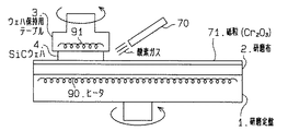
図16に代わる装置として、図17に示すように、ガスインジェクタ70から酸素ガスを研磨を行おうとする部位(研磨面)に向かって吹き付けて酸素ガスを研磨面に供給してもよい。詳しくは、SiCウェハ4と接触する直前の研磨布2(研磨布2におけるSiCウェハ4に対し上流側となる部位)に、酸素ガス噴射用ガスインジェクタ70から酸素ガスを吹き付ける。
【0073】
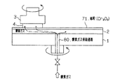
さらに、図16に代わる装置として、図18に示すように、研磨定盤1に酸素ガス供給通路80を設ける。つまり、SiCウェハ4に対し相対運動する部材を通して研磨面に酸化性気体を供給するガス通路80を設ける。そして、この通路80を通して酸素ガスを研磨布2の裏面側(SiCウェハ4に対し相対運動する部材側)から研磨布2の表面での研磨を行おうとする部位に吹き出させる。
【0074】
より詳しくは、図18の構成とする場合(研磨布2の裏面から酸素を供給する場合)、研磨定盤1にガス通路80を設けることに加え、研磨布2にはガス通過用の微小な穴を有するものを選択する。例えば、独立発泡体のポリウレタン材の研磨布は発泡部が大きければ既に表から裏に貫通する孔が形成されており、また、連続発泡体の不織布材の研磨布は酸素を通過させることが可能である。
【0075】
なお、供給する気体、つまり、少なくとも酸素を含有した気体は、酸素ガスの他に、水蒸気などの酸素を含有した他の気体を用いることができる。
また、図19に示すように、フィルム基材31上に樹脂接着剤で均一に酸化クロム粒子32を塗布したラッピングフィルム30上でSiCウェハ35を研磨する際に、ガスインジェクタ70から酸素ガス(広義には酸素を含有した気体)を吹き付けるようにすると、目詰まりを防止することができる。
【0076】
また、図20に示すように、反応を促進するために(研磨能率を向上させるべく)、SiCウェハ4を加熱しながらSiCウェハ4の研磨を行ってもよく、図20では、ヒータ90,91を用いてSiCウェハ4を加熱している。あるいは、図21に示すように、研磨布2(研磨定盤1)の端でSiCウェハ4を一部はみ出させて研磨することとし、このはみ出した領域4aに光源95から赤外光を当てて加熱するようにしてもよい。このとき、テーブル3(SiCウェハ4)を揺動させるとよい。
【0077】
このように、少なくとも研磨面を加熱する加熱手段90,91,95を設けてもよい。これは、前述の第1の実施形態や第2の実施形態において実施することもできる。
【0078】
または、酸化クロム砥粒と酸化剤が保持された研磨布、金属、セラミック、酸化クロム粒子を塗布したラッピングフィルム、あるいは酸化クロム砥粒を樹脂で固めたディスクを加熱することによって研磨能率を高めてもよい(向上させてもよい)。
【図面の簡単な説明】
【図1】第1の実施の形態におけるメカノケミカル研磨装置の概略構成図。
【図2】研磨面の面粗度の時間的変化を示す図。
【図3】研磨面の面粗度の時間的変化を示す図。
【図4】研磨面の面粗度の時間的変化を示す図。
【図5】研磨面の面粗度の時間的変化を示す図。
【図6】研磨面の面粗度の時間的変化を示す図。
【図7】研磨面の面粗度の時間的変化を示す図。
【図8】研磨時間に対する面粗度を示す図。
【図9】研磨時間に対する面粗度を示す図。
【図10】メカノケミカル研磨装置の概略構成図。
【図11】メカノケミカル研磨装置の概略構成図。
【図12】メカノケミカル研磨装置の概略構成図。
【図13】メカノケミカル研磨装置の概略構成図。
【図14】第2の実施の形態におけるメカノケミカル研磨装置の概略構成図。
【図15】メカノケミカル研磨装置の概略構成図。
【図16】第3の実施の形態におけるメカノケミカル研磨装置の概略構成図。
【図17】メカノケミカル研磨装置の概略構成図。
【図18】メカノケミカル研磨装置の概略構成図。
【図19】メカノケミカル研磨装置の概略構成図。
【図20】メカノケミカル研磨装置の概略構成図。
【図21】メカノケミカル研磨装置の概略構成図。
【図22】半導体装置の断面図。
【符号の説明】
1…研磨定盤、2…研磨布、3…ウェハ保持用テーブル、4…SiCウェハ、5…注液器、6…薬液(過酸化水素水+酸化クロム砥粒)、11…酸化クロム砥粒、42,43,44…光源、50…二酸化マンガン砥粒、51…注液器、52…薬液、60…チャンバ、70…ガスインジェクタ、80…通路、90,91…ヒータ、95…光源。[0001]
BACKGROUND OF THE INVENTION
The present invention relates to mechanochemical polishing, and more specifically, chromium (III) oxide, that is, Cr. 2 O Three The present invention relates to a polishing technique using as a polishing grain.
[0002]
[Prior art]
A power semiconductor element formed on silicon carbide (hereinafter referred to as SiC) having a physical property value larger than that of silicon (hereinafter referred to as Si) can realize performance superior to that of a Si power semiconductor element. Specifically, it can function as a semiconductor up to a high temperature by a wide energy gap (about 3 times that of Si), can have a high breakdown voltage by a high breakdown voltage (10 times), and has a high thermal conductivity (about 3). 2), the heat dissipation is excellent and the current can be further increased. Specifically, as shown in FIG. 22, for example, a SiC wafer for forming an element is a wafer in which a low impurity concentration SiC layer 101 is formed on a single crystal SiC substrate 100 having a high impurity concentration by epitaxial growth. The A device (for example, VDMOS) 103 of a type that allows current to flow in the vertical direction is formed in the low concentration layer 101. In the field of optical devices, GaN has been studied as a material capable of emitting light of a short wavelength. However, SiC has a smaller lattice mismatch with GaN than sapphire, and thus a SiC wafer forms a GaN thin film. It is also attracting attention as a base substrate.
[0003]
For SiC wafers, bulk single crystal SiC, which is grown by recrystallization from SiC powder by sublimation, is cut into a wafer shape, and then the surface (cut surface) is mirror-finished. An SiC layer or a GaN layer is epitaxially grown on this surface. In order to obtain an epitaxial layer with good crystallinity, it is required that the surface be defect-free and smooth at the atomic level.
[0004]
In general, mirror finishing of SiC is performed by polishing and smoothing the surface with diamond abrasive grains. This is a mechanical surface processing method in which the surface is cut using abrasive grains (diamond) that is harder than SiC (material to be polished). Here, the smaller the abrasive grain size is, the smoother the surface is (the surface roughness is improved), but it is not possible to suppress the occurrence of defects (working-affected layer) due to processing. Therefore, there has been a problem that a process for removing the work-affected layer such as dry etching after polishing or growing an oxide film by thermal oxidation and then wet etching with hydrofluoric acid must be performed as a post-polishing process.
[0005]
Diamond abrasive grains are expensive, and the smaller the particle size, the more expensive. Furthermore, if large abrasive grains are mixed in fine abrasive grains, the surface roughness will not improve, or scratches may occur and deep defects may occur locally. High-quality diamond abrasive grains must be used, and the abrasive grains are expensive in this respect as well. In addition, process management (control of abrasive grain size) becomes difficult. Thus, there was a problem in polishing using diamond abrasive grains.
[0006]
If polishing using a material whose hardness is lower than that of the material to be polished, the processing surface can be processed with less damage, but mechanical processing in which the abrasive particle directly cuts the material to be polished cannot be performed. If a polishing method in which mechanically brittle reaction products (oxides, compounds, etc.) are formed on the surface of the material to be polished and then peeled off with soft abrasive grains, so-called mechanochemical polishing (chemical mechanical polishing; MCP) can be achieved. Good. However, since SiC is a chemically stable material, it is difficult to form a reaction product.
[0007]
Regarding the mechanochemical polishing method of SiC, a method of polishing SiC using chromium oxide as abrasive grains has been reported (M. Kikuchi, Y. Takahashi, T Suga, S Suzuki, and Y Bando, “Mechanochemical Polishing of Silicon”). Carbide Single Crystal with Chromium (III) Oxide Abrasive ", J. Am. Ceram. Soc., 75 [1] (1992) 189). According to this, it has been reported that polishing (MCP) without residual distortion and scratches can be realized by dry polishing SiC on a disk (fixed abrasive grains) in which chromium oxide abrasive grains are hardened with resin.
[0008]
Japanese Patent Laid-Open No. 7-80770 discloses a method for improving the surface flatness of SiC by using a chromium oxide powder of free abrasive grains and a polishing surface plate having a micro Vickers hardness of 1000 to 2000. Has been proposed. These methods are polishing methods in which a reaction layer generated by a direct solid phase reaction between the material to be polished and the abrasive grains is removed by the frictional action of the abrasive grains due to a mechanochemical phenomenon at the contact point between the material to be polished and the abrasive grains.
[0009]
A polishing method using this solid phase reaction is a method proposed in Japanese Patent Publication No. 56-23746, and the above-mentioned “Mechanochemical Polishing of Silicon Carbide Single Crystal with Chromium (III) Oxide Abrasive” and Japanese Patent Laid-Open No. 7-80770. In the publication, the material to be polished is SiC and the abrasive grains are chromium oxide.
[0010]
[Problems to be solved by the invention]
However, in order to cause a solid-phase reaction, it is presumed that it is important to bring them into contact at an extremely high pressure at the contact point between the material to be polished and the abrasive grains. The processing pressure is 0.34 MPa (3.5 kgf / cm in the above-mentioned “Mechanochemical Polishing of Silicon Carbide Single Crystal with Chromium (III) Oxide Abrasive”). 2 ), 900 kgf / cm in JP-A-7-80770 2 I am experimenting with. When a high processing pressure is required, a very high pressure is applied to the polishing surface plate when polishing a large-diameter wafer. Further, when a plurality of wafers are simultaneously polished on the same polishing surface plate, a higher pressure is applied. Therefore, there has been a problem that the polishing apparatus requires a high rigidity that has not been conventionally available.
[0011]
In addition, the processing pressure is applied not only to the wafer surface, which is the contact point with the abrasive grains, but also to the entire SiC wafer, causing crystal distortion and defects, the progression of existing defects, and even non-uniform force. In such a case, there arises a problem that the wafer breaks. However, there is a problem that a solid phase reaction does not occur at a low processing pressure, and even if a reaction occurs, the rate, that is, the polishing rate becomes slow and the polishing time becomes long.
[0012]
The present invention has been made based on such a background, and an object thereof is to provide a mechanochemical polishing method and a mechanochemical polishing apparatus capable of efficiently polishing a hard material such as SiC even at a low processing pressure. It is in.
[0013]
[Means for Solving the Problems]
According to the mechanochemical polishing method of the present invention, a chromium (III) oxide powder is used as an abrasive to be polished. Silicon carbide (SiC) When polishing a wafer, an oxidizing agent is present on the polished surface. This oxidizing agent promotes the polishing efficiency.
[0014]
This is presumed to be due to the following reason. Regarding the action of chromium oxide abrasive grains, chromium oxide abrasive grains are inherently SiC It functions as a catalyst that forms oxide on the surface of SiC It is considered that the reaction efficiency is improved by increasing the amount of oxygen that reacts with the catalyst, and therefore, the polishing efficiency is promoted.
[0015]
In this way, a hard material such as SiC can be efficiently polished even at a low processing pressure. And SiC Hydrogen peroxide water is supplied as an oxidizing chemical solution on the polishing cloth disposed on the surface of the member that moves relative to the wafer, and the polishing cloth is placed on the polishing cloth. SiC 0.0098-0.294 MPa (0.1-3.0 kgf / cm 2 Polishing is performed while pressing with the processing pressure of).
[0016]
Further, as a method for supplying the oxidizing agent, the
[0017]
In addition, as described in
[0019]
Furthermore, as described in
[0021]
Moreover, as a mechanochemical polishing apparatus, the claim 7 As described in SiC A pouring device for supplying a hydrogen peroxide solution in which abrasive grains of chromium (III) oxide are dispersed as an oxidizing chemical solution on the polishing surface is disposed on the surface of a member that moves relative to the wafer. The hydrogen peroxide solution in which the chromium (III) oxide abrasive grains are dispersed is dropped onto the polishing cloth, SiC 0.0098-0.294 MPa (0.1-3.0 kgf / cm 2 ) And polishing the chromium (III) oxide abrasive grains. SiC While functioning as a catalyst for forming an oxide on the surface of the wafer, the hydrogen peroxide solution disposed on the polishing surface SiC By increasing the amount of oxygen that reacts with the wafer and polishing, it becomes more preferable.
[0022]
And claims 8 Or a heating means for heating at least the polishing surface, 9 Or a liquid injector for supplying to the polishing surface a liquid in which a solid powder having a catalytic action of a chemical reaction other than the chromium oxide powder is dispersed. 10 As described in SiC It is preferable to dispose a solid powder having a catalytic action of a chemical reaction other than the chromium oxide powder on the member that moves relative to the wafer. Where the claim 11 As described above, it is preferable to provide a light source for irradiating light to a solid powder having a catalytic action of a chemical reaction.
[0024]
Claim 12 As described in the above, when a structure in which pores or voids that are continuous in the direction perpendicular to the surface are used as the polishing cloth, the permeability from the surface of the polishing cloth in the depth direction is improved. SiC By facilitating discharge of wafer fragments and the like, it is possible to form a good polished surface free from scratches, cracks and crystal distortion.
[0025]
Where the claim 13 As described above, a structure made of at least one of synthetic fiber, glass fiber, natural fiber, synthetic resin, and natural resin may be used as the polishing cloth.
[0026]
In particular, the claims 14 A suede-type abrasive cloth with a vertical foam structure made of polyurethane material or as claimed in
[0027]
Claim 17 As described in the above, by making a structure in which independent holes or bubbles are formed on the surface and inside as the polishing cloth, the polishing cloth is hard, and the retention of abrasive grains and chemicals on the surface is improved. Uneven SiC The surface of the wafer can be flattened and smoothed in a short time. Moreover, the work-affected layer generated in the pre-polishing process (grinding process, lapping process, etc.) can be removed in a short time.
[0028]
Where the claim 18 As described above, a structure made of a synthetic resin or a natural resin may be used as the polishing cloth. In particular, the claims 19 As described above, a foamed polyurethane type abrasive cloth having a closed foam structure is suitable.
[0029]
[0030]
In particular, the claims 21 As a polishing cloth, a nonwoven fabric type cloth in which the resin acts as a fiber binder by impregnating the resin in the fiber entangled body or the resin layer itself has a continuous foam structure is used. As the undercoat layer, a two-layer polishing cloth in which a foamed polyurethane type cloth having an independent foam structure is bonded thereto is suitable.
[0031]
DETAILED DESCRIPTION OF THE INVENTION
(First embodiment)
Hereinafter, a first embodiment of the present invention will be described with reference to the drawings.
[0032]
In FIG. 1, the schematic block diagram of the mechanochemical polishing apparatus in this Embodiment is shown.
A polishing
[0033]
Further, the wafer holding table 3 and the polishing
Further, a liquid injector (nozzle) 5 is installed above the polishing
[0034]
In this way, when polishing is performed while pressing the single crystal SiC wafer (semiconductor wafer) 4 which is a material to be polished against the polishing
[0035]
When the wafer holding table 3 is swung with respect to the polishing
Next, a mechanochemical polishing method will be described.
[0036]
First, the
[0037]
When performing this polishing, a hydrogen peroxide solution (oxidant) is present on the polishing surface, and the polishing efficiency is promoted by this hydrogen peroxide solution. This is because the chromium oxide abrasive grains function as a catalyst for forming an oxide on the surface of SiC, and the hydrogen peroxide solution disposed on the polishing surface increases the oxygen that reacts with SiC, improving the reaction efficiency and improving the polishing efficiency. It is thought that promotion is planned. In this way, a hard material such as SiC can be efficiently polished even at a low processing pressure.
[0038]
Here, the minimum pressure that can be polished is the type of polishing
[0039]
In our experiments, a low processing pressure (0.34 kgf / cm 2 However, after 30 minutes of polishing, the surface roughness of 1.20 nm (centerline average roughness Ra) could be smoothed to 0.43 nm. The polishing conditions at this time were a polishing liquid in which 0.5 μm (particle diameter) chromium oxide abrasive grains (
[0040]
Detailed experimental results will be described with reference to FIGS.
The experiment was performed as follows. Single-crystal SiC (6H—SiC) was used as a sample, and the (0001) Si surface of this SiC wafer was polished. There are three polishing conditions: (i) polish while dropping hydrogen peroxide solution (oxidant) described in the present embodiment, and (ii) dry polish and (iii) wet polish for comparison. . Specifically, for polishing while dropping the hydrogen peroxide solution of (i), a solution in which chromium oxide abrasive grains (10 wt%) are dispersed in hydrogen peroxide solution (
[0041]
Polishing was evaluated by temporal changes in surface roughness. That is, the change in the surface roughness of each sample was examined.
Further, foamed polyurethane was used as the polishing cloth, and abrasive grains having a particle diameter of 0.5 μm were used as the chromium oxide. Processing pressure is 3.0kgf / cm 2 It is. The surface before polishing was a surface processed by grinding (# 8000), and there were irregularities (grinding marks) formed by grinding a diamond grindstone in a certain direction.
[0042]
In FIG. 2, the surface state after performing the above-mentioned dry polish for 10 minutes is shown. The surface roughness Ra at this time was 1.11 nm. Similarly, FIG. 3 shows the surface state after 20 minutes of dry polishing. The surface roughness Ra at this time was 0.80 nm. FIG. 4 shows the surface state after the above-described wet polishing is performed for 10 minutes. The surface roughness Ra at this time was 1.15 nm. Similarly, FIG. 5 shows the surface state after 20 minutes of wet polishing. The surface roughness Ra at this time was 0.92 nm. Further, FIG. 6 shows the surface state after polishing for 10 minutes while dropping the above-described hydrogen peroxide solution (oxidant). The surface roughness Ra at this time was 0.73 nm. Similarly, FIG. 7 shows a surface state after polishing for 20 minutes while dropping a hydrogen peroxide solution (oxidant). The surface roughness Ra at this time was 0.57 nm.
[0043]
A summary of the data thus obtained is shown in FIG. The horizontal axis in FIG. 8 represents the polishing time, and the vertical axis represents the surface roughness. From the graph showing the change in the surface roughness, it can be seen that the surface roughness is improved in a short polishing time under the condition (sample) in which the oxidizing agent is mixed. Further, at the stage of processing for 20 minutes, the grinding streaks disappeared only when the oxidizing agent was mixed. As described above, the effect of promoting the polishing was confirmed by mixing the oxidizing agent.
[0044]
Furthermore, the same experiment was conducted with the processing pressure lowered (polishing was performed under the same conditions except for the processing pressure). Specifically, up to now 3.0 kgf / cm 2 It was 0.6kgf / cm 2 Then, wet polishing (chromium oxide abrasive grains dispersed in water at 10 wt%) and oxidizer mixed polish (chromium oxide abrasive grains dispersed in hydrogen peroxide water (10%) at 10 wt%) were performed. FIG. 9 shows the experimental results (change in surface roughness).
[0045]
Comparing FIG. 9 with FIG. 8 described above, it can be seen that the difference in polishing efficiency becomes significant with and without hydrogen peroxide when the processing pressure is low between wet polishing and polishing with an oxidizing agent mixture. That is, for example, when the polishing is performed for 40 minutes, the processing pressure is 3.0 kgf / cm in wet polishing. 2 In the experiment (FIG. 8), Ra≈0.6 nm and the processing pressure is 0.6 kgf / cm. 2 In FIG. 9 (FIG. 9), Ra≈1.2 nm, whereas in the oxidizer-mixed polish, Ra≈0.6 nm in FIG. 8 and Ra≈0.6 nm in FIG. In the case of (dispersion), the polishing efficiency is greatly reduced when the processing pressure is lowered, but it is understood that the polishing efficiency is small for the polish mixed with hydrogen peroxide as an oxidizing agent.
[0046]
Although data is not shown, the processing pressure is further lowered (0.34 kgf / cm 2) under the polishing conditions of oxidant mixing. 2 The surface roughness was reduced from 1.20 nm to 0.43 nm with a polishing time of 30 minutes.
[0047]
From this, it can be seen that by mixing hydrogen peroxide as an oxidizing agent, the reduction in polishing efficiency is small even when the processing pressure is lowered.
From the above discussion and experimental results, chromium oxide (Cr 2 O Three ) Is polished, the SiC wafer can be easily and efficiently polished at a low processing pressure by mixing chromium oxide abrasive grains and an oxidizing agent. More preferably, the processing pressure for polishing the wafer is 0.0098 to 0.294 MPa (0.1 to 3.0 kgf / cm). 2 )
[0048]
If the amount of chromium oxide is the same, the smaller the abrasive particle size of chromium oxide is, the larger the surface area becomes, so that the polishing efficiency is improved and the surface roughness is also improved. Therefore, it is desirable that the abrasive grain size be 5 μm or less.
[0049]
As an application example of this embodiment, it may be carried out as follows.
As shown in FIG. 10, the same effect can be obtained even when a hydrogen peroxide solution (chemical solution 10) is dropped and polished on the polishing
[0050]
Moreover, as shown in FIG. 11, you may grind | polishing the chemical |
[0051]
Moreover, not only a polishing cloth but a metal and a ceramic may be sufficient if a chromium oxide abrasive grain and an oxidizing agent can be hold | maintained. Specifically, examples of the metal include tin, lead, aluminum, stainless steel, and copper.
[0052]
Further, instead of the polishing cloth, as shown in FIG. 12, a
[0053]
Further, as shown in FIG. 13, a solid powder having a catalytic action of a chemical reaction other than chromium oxide powder, specifically, titanium dioxide (
[0054]
Alternatively, a solid powder (TiO2) having a catalytic action of a chemical reaction other than chromium oxide powder. 2 Powder or the like) may be applied to the polishing cloth 2 (by being disposed on the side of the member that moves relative to the SiC wafer 4) and supplied to the polishing surface.
[0055]
Where such TiO 2 In the case of using powder or the like, in order to further enhance the catalytic function (in order to improve the catalytic action), as shown in FIG. 13, as shown in FIG. TiO 2 It is preferable to irradiate light to a powder or the like. Specifically, polishing may be performed while applying light to the
[0056]
In this embodiment, it is preferable to carry out the polishing cloth in consideration of the following. That is, the polishing
[0057]
In the above-described experiment, it was confirmed that the surface irregularities were efficiently flattened by using a polyurethane foam material for the polishing cloth.
However, depending on the polishing cloth, minute scratches and crystal distortion are likely to occur on the polished surface.
[0058]
Polyurethane foam is a hard polishing cloth that contains spherical foam holes. Since the foam holes are independent of each other, abrasive grains, chemicals, etc. on the polishing cloth do not penetrate into the polishing cloth. Therefore, it is difficult to eliminate a chip that has been chipped from the end of the object to be polished and dropped on the polishing cloth, and the chip tends to remain on the polishing cloth. The piece on the polishing cloth may scratch the polishing surface and cause scratches and crystal distortion.
[0059]
Therefore, if you use a polishing cloth with holes or voids that are continuous in the direction perpendicular to the surface, it is permeable in the depth direction and soft, so it is effective in preventing scratches and crystal distortion. I found that there is. In other words, when a structure in which holes or voids that are continuous in the direction perpendicular to the surface are used as the polishing cloth, the penetration from the surface of the polishing cloth in the depth direction is improved, and semiconductor wafer fragments etc. are discharged. This facilitates formation of a good polished surface free from scratches, cracks and crystal distortion. Here, as the polishing cloth, a structure made of at least one of synthetic fiber, glass fiber, natural fiber, synthetic resin, and natural resin may be used.
More specifically,
(i). Suede type polishing cloth with polyurethane foam and vertical foam structure,
(ii). A nonwoven fabric-type abrasive cloth in which the resin acts as a fiber binder by impregnating the resin in the fiber entangled body, or the resin layer itself has a continuous foam structure,
(iii). By impregnating the resin in the fiber entanglement body, the resin works as a fiber binder, or the nonwoven fabric type cloth in which the resin layer itself has a continuous foam structure is used as a base layer. A two-layered polishing cloth in which a suede type cloth with a vertical foam structure is bonded,
Are particularly suitable.
[0060]
Moreover, verification by the following experiment was performed.
The cause of scratches and crystal distortion is that the pieces of the object to be polished are caused by water polishing (a method for cleaning the surface, not for processing the surface), in which pure water is dropped on the polishing cloth. When using an independent foam polyurethane as the polishing cloth, scratches and crystal distortion occur on the surface, but when using an abrasive cloth with continuous holes or voids formed in the direction perpendicular to the surface, scratches and crystal distortion occur. I figured out from not doing. In addition, on a suede type (Supreme RN-H Rodel Nitta Co., Ltd.) polishing cloth, a solution of chromium oxide abrasive grains (10 wt%) dispersed in hydrogen peroxide (
[0061]
Therefore, if emphasis is placed on the processing efficiency of polishing, the polyurethane foam type polishing cloth in which independent holes or voids are formed on the surface and inside should be made into a high-quality polishing surface free from scratches and crystal distortion. If importance is attached, a suede type polishing cloth in which holes or voids continuous in the direction perpendicular to the surface are formed may be used.
[0062]
Here, reference will be made to a polishing cloth with an emphasis on polishing efficiency. By using a structure in which pores or bubbles that are independent on the surface and inside are formed as the polishing cloth, the polishing cloth is hard and improves the retention of abrasive grains and chemicals on the surface. The surface can be flattened and smoothed in a short time. Moreover, the work-affected layer generated in the pre-polishing process (grinding process, lapping process, etc.) can be removed in a short time. Here, as the polishing cloth, a structure made of synthetic resin or natural resin may be used. In particular, a foamed polyurethane type polishing cloth having a closed foam structure is suitable.
[0063]
Alternatively, as a polishing cloth, a cloth of a structure in which holes or voids continuous in the direction perpendicular to the surface is formed as an underlayer, and a structure in which holes or bubbles independent of the surface and the inside are formed on the cloth. By using a polishing cloth with a two-layer structure that is bonded to the cloth, the structure on the surface layer side (the cloth in contact with the wafer) provides excellent polishing speed and flattening efficiency. ) Improves the followability to the undulation and warpage of the semiconductor wafer, so that the wafer can be polished with high accuracy. In particular, as an abrasive cloth, the resin works as a fiber binder by impregnating the resin in the fiber entangled body, or the cloth layer of the nonwoven fabric type in which the resin layer itself has a continuous foam structure, For this, a two-layered polishing cloth in which a foamed polyurethane type cloth having an independent foam structure is bonded is suitable.
(Second Embodiment)
Next, the second embodiment will be described focusing on the differences from the first embodiment.
[0064]
In FIG. 14, the schematic block diagram of the mechanochemical polishing apparatus in this Embodiment is shown.
In this apparatus, the abrasive 50 applied on the
[0065]
As a polishing procedure, chromium oxide abrasive grains and manganese dioxide (MnO 2
[0066]
As an application example of this embodiment, it may be carried out as follows.
As shown in FIG. 15, chromium oxide abrasive grains and manganese dioxide (MnO 2 ) As
[0067]
In FIG. 15, as the chemical solution 52, manganese dioxide (MnO 2) is added to a dispersion medium (for example, water). 2 ) Powder may be used. In other words, solid powder with an oxidizing action (MnO 2 ) May be supplied to the polishing surface by dispersing in a liquid to be dropped.
[0068]
In addition, as the powder having an oxidizing action, manganese dioxide (MnO 2 ) Powder and manganese trioxide (Mn) 2 O Three ) Powder or MnO 2 Powder and Mn 2 O Three A mixture of these powders may also be used.
[0069]
When a wrapping film (see FIG. 12) is used, a solid powder having an oxidizing action is applied on a film to which chromium oxide abrasive grains are fixed, or a solid powder having an oxidizing action is applied to chromium oxide abrasive grains. You may mix and adhere on a film. The solid powder having an oxidizing action used at this time is MnO. 2 , Mn 2 O Three , BaCO Three , CaCO Three , SiO 2 , Fe 2 O Three , Fe Three O Four , MgO, In 2 O Three Etc.
(Third embodiment)
Next, the third embodiment will be described with a focus on differences from the first embodiment.
[0070]
In this embodiment, a gas containing at least oxygen, specifically, oxygen gas is used as the oxidizing agent.
As the configuration of the apparatus, as shown in FIG. 16, a closed container structure is employed in order to make the polishing surface in an oxidizing gas atmosphere. Specifically, the polishing
[0071]
As a polishing procedure, after setting the
[0072]
As an apparatus instead of FIG. 16, as shown in FIG. 17, oxygen gas may be blown from a
[0073]
Further, as an apparatus instead of FIG. 16, an oxygen gas supply passage 80 is provided in the polishing
[0074]
More specifically, in the case of the configuration of FIG. 18 (when oxygen is supplied from the back surface of the polishing pad 2), in addition to providing the polishing
[0075]
Note that as the gas to be supplied, that is, the gas containing at least oxygen, other gas containing oxygen such as water vapor can be used in addition to the oxygen gas.
Further, as shown in FIG. 19, when a
[0076]
In addition, as shown in FIG. 20, in order to promote the reaction (in order to improve the polishing efficiency), the
[0077]
In this way, heating means 90, 91, 95 for heating at least the polishing surface may be provided. This can also be performed in the first embodiment and the second embodiment described above.
[0078]
Or, polishing efficiency can be improved by heating a polishing cloth in which chromium oxide abrasive grains and oxidant are held, metal, ceramic, a wrapping film coated with chromium oxide particles, or a disk in which chromium oxide abrasive grains are hardened with resin. May be improved (may be improved).
[Brief description of the drawings]
FIG. 1 is a schematic configuration diagram of a mechanochemical polishing apparatus according to a first embodiment.
FIG. 2 is a diagram showing a temporal change in surface roughness of a polished surface.
FIG. 3 is a diagram showing a temporal change in surface roughness of a polished surface.
FIG. 4 is a diagram showing a temporal change in surface roughness of a polished surface.
FIG. 5 is a diagram showing a temporal change in surface roughness of a polished surface.
FIG. 6 is a diagram showing a temporal change in surface roughness of a polished surface.
FIG. 7 is a diagram showing a temporal change in surface roughness of a polished surface.
FIG. 8 is a diagram showing surface roughness with respect to polishing time.
FIG. 9 is a diagram showing surface roughness with respect to polishing time.
FIG. 10 is a schematic configuration diagram of a mechanochemical polishing apparatus.
FIG. 11 is a schematic configuration diagram of a mechanochemical polishing apparatus.
FIG. 12 is a schematic configuration diagram of a mechanochemical polishing apparatus.
FIG. 13 is a schematic configuration diagram of a mechanochemical polishing apparatus.
FIG. 14 is a schematic configuration diagram of a mechanochemical polishing apparatus according to a second embodiment.
FIG. 15 is a schematic configuration diagram of a mechanochemical polishing apparatus.
FIG. 16 is a schematic configuration diagram of a mechanochemical polishing apparatus according to a third embodiment.
FIG. 17 is a schematic configuration diagram of a mechanochemical polishing apparatus.
FIG. 18 is a schematic configuration diagram of a mechanochemical polishing apparatus.
FIG. 19 is a schematic configuration diagram of a mechanochemical polishing apparatus.
FIG. 20 is a schematic configuration diagram of a mechanochemical polishing apparatus.
FIG. 21 is a schematic configuration diagram of a mechanochemical polishing apparatus.
FIG. 22 is a cross-sectional view of a semiconductor device.
[Explanation of symbols]
DESCRIPTION OF
Claims (21)
炭化珪素ウェハに対し相対運動する部材の表面に研磨布を配し、研磨面に酸化性の薬液として過酸化水素水に前記酸化クロム(III)の砥粒が存在する状態で研磨を行うように前記研磨布上に酸化クロム(III)の砥粒が分散した過酸化水素水を供給するとともに、該研磨布に前記炭化珪素ウェハを0.0098〜0.294MPa(0.1〜3.0kgf/cm2)の加工圧力で押し付けながら研磨し、前記酸化クロム(III)の砥粒を前記炭化珪素ウェハの表面に酸化物を形成する触媒として機能させつつ、前記研磨面に配した過酸化水素水により前記炭化珪素ウェハと反応する酸素を増加させて研磨を行うようにしたことを特徴とするメカノケミカル研磨方法。In a mechanochemical polishing method for polishing a silicon carbide wafer, which is a material to be polished, using chromium (III) oxide powder as abrasive grains,
A polishing cloth is disposed on the surface of a member that moves relative to the silicon carbide wafer, and polishing is performed in a state where the abrasive grains of the chromium oxide (III) are present in the hydrogen peroxide solution as an oxidizing chemical solution on the polishing surface. A hydrogen peroxide solution in which abrasive grains of chromium (III) oxide are dispersed is supplied onto the polishing cloth, and the silicon carbide wafer is put on the polishing cloth at a rate of 0.0098 to 0.294 MPa (0.1 to 3.0 kgf / The hydrogen peroxide solution disposed on the polishing surface while polishing while pressing with a processing pressure of cm 2 ) and functioning the chromium (III) oxide abrasive grains as a catalyst for forming an oxide on the surface of the silicon carbide wafer. A mechanochemical polishing method characterized in that polishing is performed by increasing oxygen that reacts with the silicon carbide wafer.
炭化珪素ウェハに対し相対運動する部材の表面に研磨布を配するとともに、研磨面に酸化性の薬液として前記酸化クロム(III)の砥粒が分散した過酸化水素水を供給するための注液器を設け、前記研磨布上に前記酸化クロム(III)の砥粒が分散した過酸化水素水を滴下しながら、前記研磨布に前記炭化珪素ウェハを0.0098〜0.294MPa(0.1〜3.0kgf/cm2 )の加工圧力で押し付けて研磨することによって、前記酸化クロム(III)の砥粒を前記炭化珪素ウェハの表面に酸化物を形成する触媒として機能させつつ、前記研磨面に配した過酸化水素水により前記炭化珪素ウェハと反応する酸素を増加させて研磨することを特徴とするメカノケミカル研磨装置。In a mechanochemical polishing apparatus for polishing a silicon carbide wafer as a material to be polished, using chromium (III) oxide powder as abrasive grains,
Liquid injection for disposing a polishing cloth on the surface of a member that moves relative to the silicon carbide wafer and supplying hydrogen peroxide water in which the chromium (III) oxide abrasive grains are dispersed as an oxidizing chemical on the polishing surface The silicon carbide wafer is placed on the polishing cloth while the hydrogen peroxide solution in which the abrasive grains of chromium oxide (III) are dispersed is dropped onto the polishing cloth. The polishing surface is made to function as a catalyst for forming an oxide on the surface of the silicon carbide wafer by polishing by pressing and polishing at a processing pressure of ˜3.0 kgf / cm 2 ). A mechanochemical polishing apparatus for polishing by increasing the amount of oxygen that reacts with the silicon carbide wafer with hydrogen peroxide solution disposed on the substrate.
Priority Applications (2)
| Application Number | Priority Date | Filing Date | Title |
|---|---|---|---|
| JP2000259116A JP4028163B2 (en) | 1999-11-16 | 2000-08-29 | Mechanochemical polishing method and mechanochemical polishing apparatus |
| US09/709,454 US6835120B1 (en) | 1999-11-16 | 2000-11-13 | Method and apparatus for mechanochemical polishing |
Applications Claiming Priority (3)
| Application Number | Priority Date | Filing Date | Title |
|---|---|---|---|
| JP11-325437 | 1999-11-16 | ||
| JP32543799 | 1999-11-16 | ||
| JP2000259116A JP4028163B2 (en) | 1999-11-16 | 2000-08-29 | Mechanochemical polishing method and mechanochemical polishing apparatus |
Related Child Applications (1)
| Application Number | Title | Priority Date | Filing Date |
|---|---|---|---|
| JP2006003055A Division JP4345746B2 (en) | 1999-11-16 | 2006-01-10 | Mechanochemical polishing equipment |
Publications (3)
| Publication Number | Publication Date |
|---|---|
| JP2001205555A JP2001205555A (en) | 2001-07-31 |
| JP2001205555A5 JP2001205555A5 (en) | 2005-10-27 |
| JP4028163B2 true JP4028163B2 (en) | 2007-12-26 |
Family
ID=26571822
Family Applications (1)
| Application Number | Title | Priority Date | Filing Date |
|---|---|---|---|
| JP2000259116A Expired - Lifetime JP4028163B2 (en) | 1999-11-16 | 2000-08-29 | Mechanochemical polishing method and mechanochemical polishing apparatus |
Country Status (2)
| Country | Link |
|---|---|
| US (1) | US6835120B1 (en) |
| JP (1) | JP4028163B2 (en) |
Families Citing this family (43)
| Publication number | Priority date | Publication date | Assignee | Title |
|---|---|---|---|---|
| JP4177100B2 (en) * | 2000-12-01 | 2008-11-05 | 東洋ゴム工業株式会社 | Polishing pad, method for producing the same, and cushion layer for polishing pad |
| US20040134418A1 (en) * | 2002-11-08 | 2004-07-15 | Taisuke Hirooka | SiC substrate and method of manufacturing the same |
| JP4986099B2 (en) * | 2003-06-09 | 2012-07-25 | 花王株式会社 | Substrate manufacturing method |
| JP2005001018A (en) * | 2003-06-09 | 2005-01-06 | Kao Corp | Method of manufacturing substrate |
| DE102004010379A1 (en) * | 2004-03-03 | 2005-09-22 | Schott Ag | Process for the production of wafers with low-defect surfaces, the use of such wafers and electronic components obtained therefrom |
| US20080261401A1 (en) * | 2004-04-08 | 2008-10-23 | Ii-Vi Incorporated | Chemical-Mechanical Polishing of Sic Surfaces Using Hydrogen Peroxide or Ozonated Water Solutions in Combination with Colloidal Abrasive |
| US20060108325A1 (en) * | 2004-11-19 | 2006-05-25 | Everson William J | Polishing process for producing damage free surfaces on semi-insulating silicon carbide wafers |
| JP2006224252A (en) * | 2005-02-18 | 2006-08-31 | Kumamoto Univ | Polishing apparatus |
| JP2008006559A (en) * | 2006-06-30 | 2008-01-17 | Hitachi Maxell Ltd | Mirror-finishing method and machining body for mirror-finishing |
| US7651625B2 (en) * | 2006-08-28 | 2010-01-26 | Osaka University | Catalyst-aided chemical processing method and apparatus |
| JP4982742B2 (en) * | 2006-09-13 | 2012-07-25 | 国立大学法人 熊本大学 | Catalytic chemical processing method and apparatus using magnetic fine particles |
| US7781312B2 (en) * | 2006-12-13 | 2010-08-24 | General Electric Company | Silicon carbide devices and method of making |
| JP5095228B2 (en) | 2007-01-23 | 2012-12-12 | 株式会社フジミインコーポレーテッド | Polishing composition |
| JP5315573B2 (en) * | 2007-10-12 | 2013-10-16 | 国立大学法人 熊本大学 | Processing apparatus and processing method |
| CN101422872B (en) * | 2007-10-30 | 2010-05-26 | 昆明市凯跃机电塑料有限责任公司 | Air-flotation type mechanical polishing method |
| JP4732423B2 (en) * | 2007-11-13 | 2011-07-27 | 株式会社デンソー | Method for manufacturing silicon carbide semiconductor device |
| US8580346B2 (en) * | 2007-12-07 | 2013-11-12 | Pcw Holdings, Llc | Compositions and methods for restoring aircraft windows and other plastic surfaces |
| US20090148606A1 (en) * | 2007-12-07 | 2009-06-11 | Lenzsavers, Llc | Compositions and methods for restoring plastic covers and lenses |
| AU2009338803B2 (en) * | 2009-01-30 | 2015-06-04 | Pcw Holdings, Llc | Compositions and methods for restoring plastic covers and lenses |
| JP5516424B2 (en) * | 2009-02-04 | 2014-06-11 | 日立金属株式会社 | Method for manufacturing silicon carbide single crystal substrate for epitaxial growth |
| JP5364959B2 (en) | 2009-03-27 | 2013-12-11 | 国立大学法人大阪大学 | Polishing method and polishing apparatus |
| US9368367B2 (en) * | 2009-04-13 | 2016-06-14 | Sinmat, Inc. | Chemical mechanical polishing of silicon carbide comprising surfaces |
| JP4827963B2 (en) * | 2009-12-11 | 2011-11-30 | 国立大学法人九州大学 | Silicon carbide polishing liquid and polishing method thereof |
| JP2011218494A (en) * | 2010-04-09 | 2011-11-04 | Mitsui Mining & Smelting Co Ltd | Polishing slurry, and polishing method therefor |
| JP5236687B2 (en) * | 2010-05-26 | 2013-07-17 | 兵庫県 | Surface treatment method and surface treatment apparatus |
| US8778203B2 (en) * | 2010-05-28 | 2014-07-15 | Clarkson University | Tunable polish rates by varying dissolved oxygen content |
| KR101222764B1 (en) * | 2010-11-04 | 2013-01-15 | 조희태 | a scratch remove method for the car class |
| US8574032B2 (en) | 2011-03-22 | 2013-11-05 | Pcw Holdings, Llc | UV protective coating composition and method |
| US8828874B2 (en) | 2011-03-28 | 2014-09-09 | Sinmat, Inc. | Chemical mechanical polishing of group III-nitride surfaces |
| JP5743800B2 (en) * | 2011-08-15 | 2015-07-01 | 新日鉄住金マテリアルズ株式会社 | Manufacturing method of SiC wafer |
| CN103890127B (en) | 2011-10-13 | 2015-09-09 | 三井金属矿业株式会社 | Abrasive slurry and Ginding process |
| WO2013161049A1 (en) * | 2012-04-27 | 2013-10-31 | 三井金属鉱業株式会社 | SiC SINGLE CRYSTAL SUBSTRATE |
| JP6016301B2 (en) * | 2013-02-13 | 2016-10-26 | 昭和電工株式会社 | Surface processing method of single crystal SiC substrate, manufacturing method thereof, and grinding plate for surface processing of single crystal SiC substrate |
| KR20150060358A (en) * | 2013-11-26 | 2015-06-03 | 삼성디스플레이 주식회사 | An apparatus for cutting and enhancing a substrate and a method for cutting and enhancing a substrate |
| JP6381068B2 (en) * | 2014-04-08 | 2018-08-29 | 山口精研工業株式会社 | Silicon carbide substrate polishing composition |
| JP6475518B2 (en) * | 2015-03-03 | 2019-02-27 | 株式会社ディスコ | Wafer processing method |
| WO2017209050A1 (en) | 2016-06-01 | 2017-12-07 | 富士紡ホールディングス株式会社 | Polishing pad and method for manufacturing same, and method for manufacturing abrasive |
| CN109822454B (en) * | 2019-03-27 | 2023-11-10 | 西南交通大学 | Green energy-saving polishing head device of self-powered ultraviolet light source of modularized design |
| CN110524408A (en) * | 2019-09-12 | 2019-12-03 | 江苏吉星新材料有限公司 | A kind of sapphire wafer grinding method |
| JP7528681B2 (en) | 2020-09-29 | 2024-08-06 | 住友金属鉱山株式会社 | Method for polishing SiC polycrystalline substrate |
| CN113524025B (en) * | 2021-07-30 | 2023-04-28 | 河南科技学院 | SiC single crystal wafer polishing method |
| CN116285698A (en) * | 2023-02-02 | 2023-06-23 | 浙江兆晶新材料科技有限公司 | Composition for silicon carbide wafer polishing solution, preparation method and application thereof |
| CN117567942A (en) * | 2023-11-08 | 2024-02-20 | 深圳平湖实验室 | Polishing solution and preparation method and application thereof |
Family Cites Families (24)
| Publication number | Priority date | Publication date | Assignee | Title |
|---|---|---|---|---|
| US4343116A (en) * | 1979-07-26 | 1982-08-10 | Pilkington Brothers Limited | Processes for finishing glass surfaces |
| JPS5623746A (en) | 1979-08-01 | 1981-03-06 | Matsushita Electronics Corp | Manufacture of semiconductor device |
| JPH06333892A (en) | 1993-03-22 | 1994-12-02 | Fuji Electric Corp Res & Dev Ltd | Electronic device |
| US5554064A (en) * | 1993-08-06 | 1996-09-10 | Intel Corporation | Orbital motion chemical-mechanical polishing apparatus and method of fabrication |
| US5658183A (en) * | 1993-08-25 | 1997-08-19 | Micron Technology, Inc. | System for real-time control of semiconductor wafer polishing including optical monitoring |
| JPH0780770A (en) | 1993-09-14 | 1995-03-28 | Nippon Steel Corp | Mechanochemica polishing method of silicon carbide single crystal |
| US6236542B1 (en) | 1994-01-21 | 2001-05-22 | International Business Machines Corporation | Substrate independent superpolishing process and slurry |
| JP3185535B2 (en) | 1994-04-15 | 2001-07-11 | 富士電機株式会社 | Electronic device and manufacturing method thereof |
| JPH0822503A (en) | 1994-07-06 | 1996-01-23 | Sanyo Electric Co Ltd | Remote medical examination support system |
| JP3734289B2 (en) * | 1995-01-24 | 2006-01-11 | 株式会社荏原製作所 | Polishing device |
| US5674107A (en) * | 1995-04-25 | 1997-10-07 | Lucent Technologies Inc. | Diamond polishing method and apparatus employing oxygen-emitting medium |
| JP3042593B2 (en) * | 1995-10-25 | 2000-05-15 | 日本電気株式会社 | Polishing pad |
| US6012966A (en) * | 1996-05-10 | 2000-01-11 | Canon Kabushiki Kaisha | Precision polishing apparatus with detecting means |
| US5904611A (en) * | 1996-05-10 | 1999-05-18 | Canon Kabushiki Kaisha | Precision polishing apparatus |
| JP2865061B2 (en) * | 1996-06-27 | 1999-03-08 | 日本電気株式会社 | Polishing pad, polishing apparatus, and semiconductor device manufacturing method |
| JP3507628B2 (en) | 1996-08-06 | 2004-03-15 | 昭和電工株式会社 | Polishing composition for chemical mechanical polishing |
| JP3672685B2 (en) * | 1996-11-29 | 2005-07-20 | 松下電器産業株式会社 | Polishing method and polishing apparatus |
| US5816900A (en) * | 1997-07-17 | 1998-10-06 | Lsi Logic Corporation | Apparatus for polishing a substrate at radially varying polish rates |
| US5997392A (en) * | 1997-07-22 | 1999-12-07 | International Business Machines Corporation | Slurry injection technique for chemical-mechanical polishing |
| US5931718A (en) * | 1997-09-30 | 1999-08-03 | The Board Of Regents Of Oklahoma State University | Magnetic float polishing processes and materials therefor |
| JP3075352B2 (en) * | 1998-04-15 | 2000-08-14 | 日本電気株式会社 | Method and apparatus for supplying chemical mechanical polishing liquid |
| US6270395B1 (en) * | 1998-09-24 | 2001-08-07 | Alliedsignal, Inc. | Oxidizing polishing slurries for low dielectric constant materials |
| US6293851B1 (en) * | 1998-11-06 | 2001-09-25 | Beaver Creek Concepts Inc | Fixed abrasive finishing method using lubricants |
| US6077151A (en) * | 1999-05-17 | 2000-06-20 | Vlsi Technology, Inc. | Temperature control carrier head for chemical mechanical polishing process |
-
2000
- 2000-08-29 JP JP2000259116A patent/JP4028163B2/en not_active Expired - Lifetime
- 2000-11-13 US US09/709,454 patent/US6835120B1/en not_active Expired - Lifetime
Also Published As
| Publication number | Publication date |
|---|---|
| JP2001205555A (en) | 2001-07-31 |
| US6835120B1 (en) | 2004-12-28 |
Similar Documents
| Publication | Publication Date | Title |
|---|---|---|
| JP4028163B2 (en) | Mechanochemical polishing method and mechanochemical polishing apparatus | |
| JP4345746B2 (en) | Mechanochemical polishing equipment | |
| KR100528678B1 (en) | Cvd diamond coated substrate for polishing pad conditioning head and method for making same | |
| JP5455282B2 (en) | Silicon-on-insulator transfer wafer edge removal | |
| JP5331844B2 (en) | Method for double-side polishing of semiconductor wafers | |
| JP6106535B2 (en) | Method for manufacturing SiC substrate | |
| TWI506687B (en) | Verfahren zur herstellung und verfahren zur bearbeitung einer halbleiterscheibe | |
| CN1894795A (en) | Laminated semiconductor substrate and process for producing the same | |
| TW201118938A (en) | Method for producing a semiconductor wafer | |
| TW201107102A (en) | Method for producing a semiconductor wafer | |
| JP2000117616A (en) | Manufacture and working device for semiconductor device | |
| TWI272159B (en) | Polishing pad and its polishing method | |
| JP2017098322A (en) | POLISHING APPARATUS AND GaN SUBSTRATE POLISHING PROCESSING METHOD USING THE SAME | |
| JP2005007520A (en) | Abrasive pad, manufacturing method thereof, and grinding method thereof | |
| WO2014126174A1 (en) | SURFACE-PROCESSING METHOD FOR MONOCRYSTALLINE SiC SUBSTRATES, MANUFACTURING METHOD THEREFOR, AND GRINDING PLATE FOR SURFACE-PROCESSING OF MONOCRYSTALLINE SiC SUBSTRATES | |
| TW201101386A (en) | Polishing pad and method for polishing a semiconductor wafer | |
| TW200906541A (en) | Substrate processing method | |
| JP2006224252A (en) | Polishing apparatus | |
| JP2009111094A (en) | Wafer mirror polishing method | |
| JP2019102687A (en) | Polishing device | |
| JPH09246216A (en) | Manufacture of semiconductor wafer | |
| JPH1058306A (en) | Dressing device for abrasive cloth and grinding wheel for dressing abrasive cloth | |
| JP4064391B2 (en) | SiC substrate for polishing pad processing | |
| TW201131635A (en) | Method for polishing a semiconductor wafer | |
| JP2001334457A (en) | Wrap plate and machining device using it |
Legal Events
| Date | Code | Title | Description |
|---|---|---|---|
| A521 | Request for written amendment filed |
Free format text: JAPANESE INTERMEDIATE CODE: A523 Effective date: 20050804 |
|
| A621 | Written request for application examination |
Free format text: JAPANESE INTERMEDIATE CODE: A621 Effective date: 20050804 |
|
| A871 | Explanation of circumstances concerning accelerated examination |
Free format text: JAPANESE INTERMEDIATE CODE: A871 Effective date: 20050804 |
|
| A975 | Report on accelerated examination |
Free format text: JAPANESE INTERMEDIATE CODE: A971005 Effective date: 20051028 |
|
| A131 | Notification of reasons for refusal |
Free format text: JAPANESE INTERMEDIATE CODE: A131 Effective date: 20051108 |
|
| A521 | Request for written amendment filed |
Free format text: JAPANESE INTERMEDIATE CODE: A523 Effective date: 20060110 |
|
| A02 | Decision of refusal |
Free format text: JAPANESE INTERMEDIATE CODE: A02 Effective date: 20060207 |
|
| A521 | Request for written amendment filed |
Free format text: JAPANESE INTERMEDIATE CODE: A523 Effective date: 20060405 |
|
| A911 | Transfer to examiner for re-examination before appeal (zenchi) |
Free format text: JAPANESE INTERMEDIATE CODE: A911 Effective date: 20060410 |
|
| A912 | Re-examination (zenchi) completed and case transferred to appeal board |
Free format text: JAPANESE INTERMEDIATE CODE: A912 Effective date: 20060616 |
|
| A521 | Request for written amendment filed |
Free format text: JAPANESE INTERMEDIATE CODE: A523 Effective date: 20070903 |
|
| A61 | First payment of annual fees (during grant procedure) |
Free format text: JAPANESE INTERMEDIATE CODE: A61 Effective date: 20071011 |
|
| FPAY | Renewal fee payment (event date is renewal date of database) |
Free format text: PAYMENT UNTIL: 20101019 Year of fee payment: 3 |
|
| R150 | Certificate of patent or registration of utility model |
Ref document number: 4028163 Country of ref document: JP Free format text: JAPANESE INTERMEDIATE CODE: R150 Free format text: JAPANESE INTERMEDIATE CODE: R150 |
|
| FPAY | Renewal fee payment (event date is renewal date of database) |
Free format text: PAYMENT UNTIL: 20101019 Year of fee payment: 3 |
|
| FPAY | Renewal fee payment (event date is renewal date of database) |
Free format text: PAYMENT UNTIL: 20111019 Year of fee payment: 4 |
|
| FPAY | Renewal fee payment (event date is renewal date of database) |
Free format text: PAYMENT UNTIL: 20121019 Year of fee payment: 5 |
|
| FPAY | Renewal fee payment (event date is renewal date of database) |
Free format text: PAYMENT UNTIL: 20121019 Year of fee payment: 5 |
|
| FPAY | Renewal fee payment (event date is renewal date of database) |
Free format text: PAYMENT UNTIL: 20131019 Year of fee payment: 6 |
|
| R250 | Receipt of annual fees |
Free format text: JAPANESE INTERMEDIATE CODE: R250 |
|
| R250 | Receipt of annual fees |
Free format text: JAPANESE INTERMEDIATE CODE: R250 |
|
| R250 | Receipt of annual fees |
Free format text: JAPANESE INTERMEDIATE CODE: R250 |
|
| R250 | Receipt of annual fees |
Free format text: JAPANESE INTERMEDIATE CODE: R250 |
|
| R250 | Receipt of annual fees |
Free format text: JAPANESE INTERMEDIATE CODE: R250 |
|
| R250 | Receipt of annual fees |
Free format text: JAPANESE INTERMEDIATE CODE: R250 |
|
| EXPY | Cancellation because of completion of term |