JP4021189B2 - Camera shutter device - Google Patents
Camera shutter device Download PDFInfo
- Publication number
- JP4021189B2 JP4021189B2 JP2001382572A JP2001382572A JP4021189B2 JP 4021189 B2 JP4021189 B2 JP 4021189B2 JP 2001382572 A JP2001382572 A JP 2001382572A JP 2001382572 A JP2001382572 A JP 2001382572A JP 4021189 B2 JP4021189 B2 JP 4021189B2
- Authority
- JP
- Japan
- Prior art keywords
- magnetic pole
- drive source
- rotor
- shutter blade
- shutter
- Prior art date
- Legal status (The legal status is an assumption and is not a legal conclusion. Google has not performed a legal analysis and makes no representation as to the accuracy of the status listed.)
- Expired - Fee Related
Links
- 230000002093 peripheral effect Effects 0.000 claims description 12
- 238000005452 bending Methods 0.000 claims description 5
- 230000005284 excitation Effects 0.000 claims 1
- 238000010586 diagram Methods 0.000 description 6
- XEEYBQQBJWHFJM-UHFFFAOYSA-N Iron Chemical compound [Fe] XEEYBQQBJWHFJM-UHFFFAOYSA-N 0.000 description 4
- 229910052742 iron Inorganic materials 0.000 description 2
- 230000000694 effects Effects 0.000 description 1
- GGCZERPQGJTIQP-UHFFFAOYSA-N sodium;9,10-dioxoanthracene-2-sulfonic acid Chemical compound [Na+].C1=CC=C2C(=O)C3=CC(S(=O)(=O)O)=CC=C3C(=O)C2=C1 GGCZERPQGJTIQP-UHFFFAOYSA-N 0.000 description 1
Images

Landscapes
- Shutters For Cameras (AREA)
Description
【0001】
【発明の属する技術分野】
本発明は、露光用の開口部を開閉するカメラ用シャッタ装置に関し、特に、開き用シャッタ羽根と閉じ用シャッタ羽根とを別々に駆動する駆動源を備えたカメラ用シャッタ装置に関する。
【0002】
【従来の技術】
従来のカメラ用シャッタ装置として、例えば実開平6−37834号公報、実開平6−28843号公報等に記載されたものが知られている。これらの公報に開示の装置は、露光用の開口部に対して開き動作を行なう開き用シャッタ羽根及び閉じ動作を行なう閉じ用シャッタ羽根、開き用シャッタ羽根を駆動する第1モータ、閉じ用シャッタ羽根を駆動する第2モータを備えている。
そして、撮影待機状態から、第1モータの駆動により閉じ状態にあった開き用シャッタ羽根が開口部を開放し、続いて、第2モータの駆動により開き状態にあった閉じ用シャッタ羽根が開口部を閉鎖することで、露光動作が行なわれる。
【0003】
【発明が解決しようとする課題】
ところで、上記カメラ用シャッタ装置において、第1モータ及び第2モータは、所定の角度範囲を回動するロータ、ロータの外周面との間に磁気的な吸引力及び反発力を生じるヨークあるいは鉄ピン等を備えた電磁アクチュエータであり、ロータの駆動ピンが開き用シャッタ羽根及び閉じ用シャッタ羽根の一端側に駆動力を及ぼして、開き用シャッタ羽根及び閉じ用シャッタ羽根がそれぞれ所定の軸回りに揺動することで、開口部の開閉動作を行なうものである。
【0004】
したがって、ロータの外周面とヨークあるいは鉄ピンとの間に生じる磁気的吸引力及び反発力だけで回転駆動力を得るには限界がある。すなわち、開き用シャッタ羽根及び閉じ用シャッタ羽根の動作による開口波形は、図9に示すように、開き用シャッタ羽根が開き動作を開始してから終了するまでに時間T0を要し、又、閉じ用シャッタ羽根が閉じ動作を開始してから終了するまでに時間T0を要し、比較的緩やかに変化する形状となる。それ故に、露光時間Tを短くするには一定の限界があった。
【0005】
本発明は、上記従来技術の問題点に鑑みて成されたものであり、その目的とするところは、構造の簡略化、低消費電力化を図りつつ、露光動作の高速化を行なえるカメラ用シャッタ装置を提供することにある。
【0006】
【課題を解決するための手段】
本発明のカメラ用シャッタ装置は、露光用開口部の開き動作を行なう第1シャッタ羽根及び閉じ動作を行なう第2シャッタ羽根と、第1シャッタ羽根及び第2シャッタ羽根を別々に駆動する第1駆動源及び第2駆動源とを備え、第1駆動源及び第2駆動源は、外周面を二分するように異なる磁極に着磁され所定の角度範囲を回動するロータ、励磁用のコイル、ロータの外周面に対向するように配置され異なる磁極を発生し得る二つの磁極部を有するヨークを各々含み、第1駆動源及び第2駆動源のロータが初期位置から最大回転位置まで回転することで開き動作及び閉じ動作を行なうカメラ用シャッタ装置であって、上記第1駆動源及び第2駆動源のロータは、一方の磁極に着磁されかつ径方向外側に向かって突出する突出部を有し、上記第1駆動源及び第2駆動源のヨークは、ロータの最大回転位置側のヨークの磁極部の近傍に配置され、磁極部と同じ磁極を生じ、ロータが最大回転位置に向けて回転する際に、突出部の回転方向において突出部に対向して吸引力を及ぼしロータの回転を補助する補助磁極片を有する、ことを特徴としている。
この構成によれば、コイルへの通電により、第1駆動源及び第2駆動源が第1シャッタ羽根に開き動作及び第2シャッタ羽根に閉じ動作を行なわせる際に、各々の補助磁極片が対応する各々の突出部に対して突出部の回転方向(すなわち、回転軌道上)において対向して力(吸引力)を及ぼして各々のロータの回転を補助する。これにより、開き動作及び閉じ動作、すなわち露光動作が高速化される。
【0008】
上記構成において、補助磁極片は、ヨークの一部を折り曲げて形成されている、構成を採用できる。
この構成によれば、補助磁極片がヨークと一体的に形成されるため、部品点数の増加を防止でき、構造の簡略化、組み付けの容易化、低消費電力化を行ないつつ、回転補助力を確保できる。
【0009】
上記構成において、第1駆動源及び第2駆動源のロータは、第1シャッタ羽根及び第2シャッタ羽根に連結される駆動ピンを有し、駆動ピンは突出部を兼ねる、構成を採用できる。
この構成によれば、駆動ピンに突出部を兼ねさせることで、ロータの構造を簡略化しつつ、回転補助力を確保できる。
【0010】
【発明の実施の形態】
以下、本発明の実施の形態について、添付図面を参照しつつ説明する。
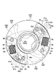
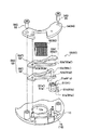
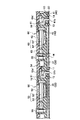
図1ないし図8は、本発明に係るカメラ用シャッタ装置の一実施形態を示すものであり、図1は装置の正面図、図2は駆動源の分解斜視図、図3は装置の展開断面図、図4は駆動源の作動説明図、図5ないし図7はシャッタ羽根の動作を示す図、図8は開口波形を示す図である。
【0011】
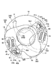
この装置は、図1に示すように、露光用の開口部10a,20aを形成する地板10及び裏板20、地板10に揺動自在に配置されて開口部10a,20aの開き動作を行なう第1シャッタ羽根30、地板10に揺動自在に配置されて開口部10a,20aの閉じ動作を行なう第2シャッタ羽根40、第1シャッタ羽根30を駆動する第1駆動源としての第1電磁アクチュエータ50、第2シャッタ羽根40を駆動する第2駆動源としての第2電磁アクチュエータ60等を備えている。
【0012】
地板10及び裏板20は、略円板状に形成されている。裏板20は、図3に示すように、地板10の背面に所定の間隔を空けて結合され、地板10と共に第1シャッタ羽根30及び第2シャッタ羽根40を収容する羽根室Wを画定している。
【0013】
第1シャッタ羽根30は、図1、図5ないし図7に示すように、2枚のシャッタ羽根31,32からなり、支持孔31a,32a、長孔31b,32bを有し、地板10の支軸11,12により揺動自在に支持されている。
第2シャッタ羽根40は、図1、図5ないし図7に示すように、2枚のシャッタ羽根41,42からなり、支持孔41a,42a、長孔41b,42bを有し、地板10の支軸13,14により揺動自在に支持されている。
【0014】
第1電磁アクチュエータ50は、図1ないし図3に示すように、外周面を二分するように異なる磁極(N極及びS極)に着磁され所定の角度範囲を回動するロータ51、励磁用のコイル52、ロータ51の外周面に対向するように配置され異なる磁極を発生し得る二つの磁極部を有するヨーク53を有する。
【0015】
ロータ51は、図2及び図3に示すように、円柱状をなす本体51aと、本体51aに一体的に形成されると共に径方向外側に向かって突出する突出部としての駆動ピン51bを有する。本体51aは、回転中心線Cを通る面にて二分される一方の半体51a´がN極に、他方の半体51a´´がS極に着磁されており、駆動ピン51bもN極に着磁されている。尚、駆動ピン51bは、第1シャッタ羽根30の長孔31b,32bに連結される。
そして、本体51aに形成された貫通孔に地板10の支軸15が挿通されて、ロータ51は所定の角度範囲を回動自在に支持されている。
尚、一方の半体51a´がS極に、他方の半体51a´´がN極に着磁され、駆動ピン51bがS極に着磁されていてもよい。
【0016】
ヨーク53は、下側ヨーク53´及び上側ヨーク53´´からなる。下側ヨーク53´は、コイル52への通電時にお互いに異なる磁極を発生する第1磁極部53a´及び第2磁極部53b´を有する。上側ヨーク53´´は、コイル52への通電時にお互いに異なる磁極を発生する第1磁極部53a´´及び第2磁極部53b´´を有する。
また、第2磁極部53b´の近傍には、一部を折り曲げて一体的に形成された補助磁極片53c´を有する。補助磁極片53c´は、ロータ51が最大回転位置に向かって回転する際に、その回転を補助する力(ここでは吸引力)を、駆動ピン51bに対して及ぼすものである。
【0017】
そして、図1ないし図3に示すように、ロータ51が支軸15に回動自在に取り付けられ、下側ヨーク53´及び上側ヨーク53´´が積層され、その上からカバー板54が取り付けられ、ネジ55により固定されている。
【0018】
第2電磁アクチュエータ60は、図1ないし図3に示すように、外周面を二分するように異なる磁極(N極及びS極)に着磁され所定の角度範囲を回動するロータ61、励磁用のコイル62、ロータ61の外周面に対向するように配置され異なる磁極を発生し得る二つの磁極部を有するヨーク63を有する。
【0019】
ロータ61は、図2及び図3に示すように、円柱状をなす本体61aと、本体61aに一体的に形成されると共に径方向外側に向かって突出する突出部としての駆動ピン61bを有する。本体61aは、回転中心線Cを通る面にて二分される一方の半体61a´がN極に、他方の半体61a´´がS極に着磁されており、駆動ピン61bもN極に着磁されている。尚、駆動ピン61bは、第2シャッタ羽根40の長孔41b,42bに連結される。
そして、本体61aに形成された貫通孔に地板10の支軸16が挿通されて、ロータ61は所定の角度範囲を回動自在に支持されている。
尚、一方の半体61a´がS極に、他方の半体61a´´がN極に着磁され、駆動ピン61bがS極に着磁されていてもよい。
【0020】
ヨーク63は、下側ヨーク63´及び上側ヨーク63´´からなる。下側ヨーク63´は、コイル62への通電時にお互いに異なる磁極を発生する第1磁極部63a´及び第2磁極部63b´を有する。上側ヨーク63´´は、コイル62への通電時にお互いに異なる磁極を発生する第1磁極部63a´´及び第2磁極部63b´´を有する。
【0021】
また、第2磁極部63b´の近傍には、一部を折り曲げて一体的に形成された補助磁極片63c´を有する。補助磁極片63c´は、ロータ61が最大回転位置に向かって回転する際に、その回転を補助する力(ここでは吸引力)を駆動ピン61bに対して及ぼすものである。
【0022】
そして、図1ないし図3に示すように、ロータ61が支軸16に回動自在に取り付けられ、下側ヨーク63´及び上側ヨーク63´´が積層され、その上からカバー板64が取り付けられ、ネジ65により固定されている。
【0023】
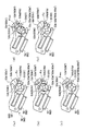
次に、第1電磁アクチュエータ50及び第2電磁アクチュエータ60の動作について、図4に基づき説明する。
先ず、コイル52,62への非通電の状態で、ロータ51,61は、図4(a)に示すように、時計回りの回転端である初期位置θoに位置している。すなわち、ロータ51,61の磁極中心Pnは磁気的吸引力により第1磁極部53a´,53a´´,63a´,63a´´に引き付けられ、磁極中心Psは磁気的吸引力により第2磁極部53b´,53b´´,63b´,63b´´に引き付けられて、ロータ51,61は時計回りに付勢されてストッパ(不図示)により回転が規制された状態に保持されている。
【0024】
この待機状態において、コイル52,62が通電されると、図4(b)に示すように、第1磁極部53a´,53a´´,63a´,63a´´にN極が発生し、又、第2磁極部53b´,53b´´,63b´,63b´´及び補助磁極片53c´,63c´にS極が発生する。
これにより、第1磁極部53a´,53a´´,63a´,63a´´は、磁極中心Pn側に対して反発力を生じ、磁極中心Ps側に対して吸引力を生じる。また、第2磁極部53b´,53b´´,63b´,63b´´は、磁極中心Pn側に対して吸引力を生じ、磁極中心Ps側に対して反発力を生じる。
さらに、補助磁極片53c´,63c´は、駆動ピン51b,61bに対して吸引力を生じる。
【0025】
したがって、ロータ51,61は、反時計回りに回転して、図4(c)に示すように、最大回転位置θmaxに至り、ストッパ(不図示)にて回転が規制される。この回転動作において、特に、補助磁極片53c´,63c´が及ぼす吸引力は、回転中心Cから偏倚した位置にある駆動ピン51b,61bに作用するため、ロータ51,61の外周面に作用する場合に比べて、大きな回転トルクを生じることになる。その結果、ロータ51,61は、初期位置θoから最大回転位置θmax(反時計回りの回転端)まで高速にて回転する。
【0026】
ロータ51,61が最大回転位置θmaxにある状態において、コイル52,62への通電を断つと、磁気的吸引力によりその位置に保持される。すなわち、磁極中心Psは磁気的吸引力により第1磁極部53a´,53a´´,63a´,63a´´に引き付けられ、磁極中心Pnは磁気的吸引力により第2磁極部53b´,53b´´,63b´,63b´´に引き付けられ、さらに、駆動ピン51b,61bは磁気的吸引力により補助磁極片53c´,63c´に引き付けられ、ロータ51,61は反時計回りに付勢されてストッパ(不図示)により回転が規制された状態に保持される。
【0027】
一方、図4(c)に示す状態において、コイル52,62が逆向きに通電されると、図4(d)に示すように、第1磁極部53a´,53a´´,63a´,63a´´にS極が発生し、又、第2磁極部53b´,53b´´,63b´,63b´´及び補助磁極片53c´,63c´にN極が発生する。
これにより、第1磁極部53a´,53a´´,63a´,63a´´は、磁極中心Pn側に対して吸引力を生じ、磁極中心Ps側に対して反発力を生じる。また、第2磁極部53b´,53b´´,63b´,63b´´は、磁極中心Pn側に対して反発力を生じ、磁極中心Ps側に対して吸引力を生じる。
さらに、補助磁極片53c´,63c´は、駆動ピン51b,61bに対して反発力を生じる。
【0028】
したがって、ロータ51,61は、時計回りに回転して、図4(e)に示すように、初期位置θoに至り、ストッパ(不図示)にて回転が規制される。この回転動作において、特に、補助磁極片53c´,63c´が及ぼす反発力は、回転中心Cから偏倚した位置にある駆動ピン51b,61bに作用するため、ロータ51,61の外周面に作用する場合に比べて、大きな回転トルクを生じることになる。その結果、ロータ51,61は、最大回転位置θmaxから初期位置θoまで高速にて回転する。
そして、コイル52,62への通電を断つと、前述のように磁気的付勢力により初期位置θoに保持される。
【0029】
次に、上記の構成をなすカメラ用シャッタ装置が銀塩フィルム式のカメラに搭載された場合の動作について、図5ないし図7に基づき説明する。
先ず、撮影待ちの待機状態において、図5に示すように、第1電磁アクチュエータ50のロータ51は初期位置θoにあり、第1シャッタ羽根30はストッパ17に当接して開口部10a,20aを全開した開放位置に位置決めされている。また、第2電磁アクチュエータ60のロータ61は初期位置θoにあり、第2シャッタ羽根40はストッパ18に当接して開口部10a,20aを全閉した閉鎖位置に位置決めされている。
【0030】
続いて、レリーズ動作が行なわれると、コイル52が通電されて、ロータ51が最大回転位置θmaxに向けて回転する。このとき、前述したように駆動ピン51bに対して補助磁極片53c´が吸引力を及ぼすため、強力な回転トルクが得られ、ロータ51は高速にて回転する。
したがって、第1シャッタ羽根30は、図5に示すように開口部10a,20aを閉鎖した閉鎖位置から、図6に示すように、開口部10a,20aを開放する開放位置に向け、高速で移動して開き動作を行なう。
【0031】
また、所定時間をおいて、コイル62が通電されて、ロータ61が最大回転位置θmaxに向けて回転する。このとき、前述したように駆動ピン61bに対して補助磁極片63c´が吸引力を及ぼすため、強力な回転トルクが得られ、ロータ61は高速にて回転する。
したがって、第2シャッタ羽根40は、図6に示すように開口部10a,20aを開放した開放位置から、図7に示すように開口部10a,20aを閉鎖する閉鎖位置に向け、高速で移動して閉じ動作を行なう。
【0032】
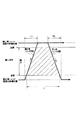
上記第1シャッタ羽根30の開き動作及び第2シャッタ羽根40の閉じ動作による露光動作においては、図8に示すように、第1シャッタ羽根30及び第2シャッタ羽根40の移動に要する時間T1は、従来の時間T0(図9参照)よりも短く、開口波形は従来に比べて急峻な勾配をもつ形状となる。すなわち、コイル52,62に通電する電流値を大きくするこなく、露光動作を高速化できる。
【0033】
その後、コイル52が逆向きに通電されると、ロータ51が初期位置θoに至り、第1シャッタ羽根30が図5に示す閉鎖位置に戻る。続けて、コイル62が逆向きに通電されると、ロータ61が初期位置θoに至り、第2シャッタ羽根40が図5に示す開放位置に戻る。これにより、再び撮影待ちの待機状態となる。尚、これらの戻り動作の際にも、補助磁極片53c´,63c´が駆動ピン51b,61bに対して反発力を及ぼし、ロータ51,61は高速にて初期位置θoに至るため、第1シャッタ羽根30及び第2シャッタ羽根40の戻り動作を高速化できる。
【0034】
上記実施形態においては、補助磁極片53c´,63c´を、最大回転位置θmax側に配置して、ロータ51,61が最大回転位置θmaxに向けて回転する際に吸引力を及ぼすようにしたが、これに限定されるものではなく、補助磁極片を初期位置θo側に配置して、ロータ51,61が最大回転位置θmaxに向けて回転する際に反発力を及ぼすようにしてもよい。
また、補助磁極片を初期位置θo側と最大回転位置θmax側とに配置して、ロータ51,61が最大回転位置θmaxに向けて回転する際に、反発力と吸引力を及ぼすようにして、より強力な回転補助力(回転トルク)が得られるようにしてもよい。
【0035】
また、上記実施形態においては、補助磁極片53c´,63c´が力を及ぼす突出部として、駆動ピン51b,61bを兼用したが、これに限定されるものではなく、駆動ピン51b,61bとは別に、専用の突出部をロータ51,61に設けてもよい。
【0036】
【発明の効果】
以上述べたように、本発明のカメラ用シャッタ装置によれば、露光用開口部の開き動作を行なう第1シャッタ羽根及び閉じ動作を行なう第2シャッタ羽根、第1シャッタ羽根及び第2シャッタ羽根を別々に駆動する第1駆動源及び第2駆動源とを備えた構成において、ロータが最大回転位置に移動する際に、回転を補助するべくロータの突出部に対して力を及ぼす補助磁極片をヨークに設けたことにより、第1シャッタ羽根に開き動作及び第2シャッタ羽根に閉じ動作を行なわせる際に、各々の補助磁極片が対応する各々の突出部に力を及ぼして各々のロータの回転を補助する。これにより、低消費電力化、構造の簡略化を行ないつつ、露光動作の高速化を達成できる。
特に、補助磁極片を、ヨークの一部を折り曲げて形成することで、部品点数の増加を防止でき、構造の簡略化、組み付けの容易化等を達成できる。また、ロータの駆動ピンを突出部として兼用することで、ロータの構造を簡略化しつつ、回転補助力を確保することができる。
【図面の簡単な説明】
【図1】本発明に係るカメラ用シャッタ装置の一実施形態を示す正面図である。
【図2】図1に示すカメラ用シャッタ装置に用いられる第1駆動源及び第2駆動源を示す分解斜視図である。
【図3】図1に示すカメラ用シャッタ装置の展開断面図である。
【図4】図1に示すカメラ用シャッタ装置に用いられる第1駆動源及び第2駆動源の動作を説明するものであり、(a)〜(e)は、それぞれの動作におけるロータの回転位置及びヨークに発生する磁極を示す状態図である。
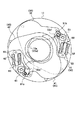
【図5】図1に示すカメラ用シャッタ装置において、撮影待ちの待機状態を示す正面図である。
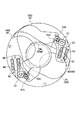
【図6】図1に示すカメラ用シャッタ装置において、開き動作を行なう第1シャッタ羽根が開放位置に移動した状態を示す正面図である。
【図7】図1に示すカメラ用シャッタ装置において、開き動作を行なう第1シャッタ羽根が開放位置に移動した後、閉じ動作を行なう第2シャッタ羽根が閉鎖位置に移動した状態を示す正面図である。
【図8】図1に示すカメラ用シャッタ装置において、第1シャッタ羽根及び第2シャッタ羽根による露光動作での開口波形を示す図である。
【図9】従来のカメラ用シャッタ装置における露光動作での開口波形を示す図である。
【符号の説明】
10 地板
10a 露光用の開口部
11,12,13,14,15,16 支軸
17,18 ストッパ
30 第1シャッタ羽根
40 第2シャッタ羽根
50 第1電磁アクチュエータ(第1駆動源)
51 ロータ
51a 本体
51b 駆動ピン(突出部)
52 コイル
53 ヨーク
53´ 下側ヨーク
53´´ 上側ヨーク
53a´,53a´´ 第1磁極部
53b´,53b´´ 第2磁極部
53c´ 補助磁極片
60 第2電磁アクチュエータ(第2駆動源)
61 ロータ
61a 本体
61b 駆動ピン(突出部)
62 コイル
63 ヨーク
63´ 下側ヨーク
63´´ 上側ヨーク
63a´,63a´´ 第1磁極部
63b´,63b´´ 第2磁極部
63c´ 補助磁極片
θo 初期位置
θmax 最大回転位置[0001]
BACKGROUND OF THE INVENTION
The present invention relates to a camera shutter device that opens and closes an opening for exposure, and more particularly to a camera shutter device that includes a drive source that separately drives an opening shutter blade and a closing shutter blade.
[0002]
[Prior art]
As conventional camera shutter devices, for example, those described in Japanese Utility Model Laid-Open Nos. 6-37834 and 6-28843 are known. The devices disclosed in these publications include an opening shutter blade that opens an opening for exposure, a closing shutter blade that performs a closing operation, a first motor that drives the opening shutter blade, and a closing shutter blade. The 2nd motor which drives is provided.
Then, from the photographing standby state, the opening shutter blades that are closed by driving the first motor open the opening, and then the closing shutter blades that are open by driving the second motor are the opening. By closing, an exposure operation is performed.
[0003]
[Problems to be solved by the invention]
By the way, in the camera shutter device, the first motor and the second motor are a rotor that rotates within a predetermined angular range, a yoke or an iron pin that generates a magnetic attractive force and a repulsive force between the outer peripheral surface of the rotor and the rotor. The driving pin of the rotor exerts a driving force on one end side of the opening shutter blade and the closing shutter blade so that the opening shutter blade and the closing shutter blade swing around a predetermined axis, respectively. By moving, the opening and closing operation is performed.
[0004]
Therefore, there is a limit in obtaining the rotational driving force only by the magnetic attractive force and the repulsive force generated between the outer peripheral surface of the rotor and the yoke or the iron pin. That is, as shown in FIG. 9, the opening waveform due to the operation of the opening shutter blade and the closing shutter blade takes time T0 from the start to the end of the opening shutter blade, and the closing waveform is closed. It takes a time T0 from the start to the end of the closing operation of the shutter blade for closing, and the shape changes relatively slowly. Therefore, there is a certain limit to shorten the exposure time T.
[0005]
The present invention has been made in view of the above-described problems of the prior art, and the object of the present invention is for a camera capable of speeding up an exposure operation while simplifying the structure and reducing power consumption. It is to provide a shutter device.
[0006]
[Means for Solving the Problems]
The camera shutter device of the present invention includes a first shutter blade that performs an opening operation of an exposure opening, a second shutter blade that performs a closing operation, and a first drive that separately drives the first shutter blade and the second shutter blade. And a second driving source, and the first driving source and the second driving source are magnetized by different magnetic poles so as to bisect the outer peripheral surface and rotate within a predetermined angle range, an exciting coil, and a rotor Each of the yokes having two magnetic pole portions that are arranged so as to face the outer peripheral surface of each of the two magnetic pole portions and can generate different magnetic poles, and the rotors of the first drive source and the second drive source are rotated from the initial position to the maximum rotation position. A shutter device for a camera that performs an opening operation and a closing operation, wherein the rotors of the first driving source and the second driving source have a protruding portion that is magnetized on one magnetic pole and protrudes radially outward. , Above The yokes of the drive source and the second drive source are arranged in the vicinity of the magnetic pole part of the yoke on the maximum rotational position side of the rotor, generate the same magnetic pole as the magnetic pole part, and protrude when the rotor rotates toward the maximum rotational position. And an auxiliary magnetic pole piece for assisting the rotation of the rotor by exerting an attractive force opposite to the projecting portion in the rotation direction of the portion .
According to this configuration, when the first drive source and the second drive source cause the first shutter blade to perform the opening operation and the second shutter blade to perform the closing operation by energizing the coil, each auxiliary magnetic pole piece responds. each of the rotational direction of the protrusion against the protrusion (i.e., the rotational orbit) for assisting the rotation of each rotor exerts opposite to the force (attraction force) in the. Thereby, the opening operation and the closing operation, that is, the exposure operation is speeded up.
[0008]
In the above configuration, the auxiliary magnetic pole piece may be formed by bending a part of the yoke.
According to this configuration, since the auxiliary magnetic pole piece is formed integrally with the yoke, it is possible to prevent an increase in the number of parts, simplifying the structure, facilitating assembly, and reducing the power consumption, while providing the auxiliary rotation force. It can be secured.
[0009]
In the above configuration, the rotor of the first drive source and the second drive source may have a drive pin connected to the first shutter blade and the second shutter blade, and the drive pin may also serve as a protrusion.
According to this configuration, it is possible to secure the rotation assist force while simplifying the structure of the rotor by causing the drive pin to also serve as the protruding portion.
[0010]
DETAILED DESCRIPTION OF THE INVENTION
Hereinafter, embodiments of the present invention will be described with reference to the accompanying drawings.
1 to 8 show an embodiment of a camera shutter device according to the present invention. FIG. 1 is a front view of the device, FIG. 2 is an exploded perspective view of a drive source, and FIG. FIGS. 4A and 4B are diagrams for explaining the operation of the drive source, FIGS. 5 to 7 are diagrams illustrating the operation of the shutter blades, and FIG. 8 is a diagram illustrating the opening waveform.
[0011]
As shown in FIG. 1, this apparatus is arranged in a swingable manner on the
[0012]
The
[0013]
As shown in FIGS. 1 and 5 to 7, the
As shown in FIGS. 1 and 5 to 7, the
[0014]
As shown in FIGS. 1 to 3, the first
[0015]
As shown in FIGS. 2 and 3, the
Then, the
One half 51a ′ may be magnetized to the S pole, the
[0016]
The
Further, in the vicinity of the second
[0017]
As shown in FIGS. 1 to 3, the
[0018]
As shown in FIGS. 1 to 3, the second
[0019]
As shown in FIGS. 2 and 3, the
Then, the
One half 61a 'may be magnetized to the S pole, the
[0020]
The
[0021]
Further, in the vicinity of the second
[0022]
As shown in FIGS. 1 to 3, the
[0023]
Next, operations of the first
First, in a state where the
[0024]
When the
Thereby, the first
Further, the auxiliary
[0025]
Therefore, the
[0026]
In the state where the
[0027]
On the other hand, when the
Accordingly, the first
Further, the auxiliary
[0028]
Accordingly, the
When the energization of the
[0029]
Next, the operation when the camera shutter device having the above-described configuration is mounted on a silver salt film type camera will be described with reference to FIGS.
First, in a standby state waiting for photographing, as shown in FIG. 5, the
[0030]
Subsequently, when a release operation is performed, the
Therefore, the
[0031]
In addition, after a predetermined time, the
Accordingly, the
[0032]
In the exposure operation by the opening operation of the
[0033]
Thereafter, when the
[0034]
In the above embodiment, the auxiliary
Further, the auxiliary magnetic pole pieces are arranged on the initial position θo side and the maximum rotation position θmax side so that when the
[0035]
Further, in the above embodiment, the drive pins 51b and 61b are also used as the protrusions to which the auxiliary
[0036]
【The invention's effect】
As described above, according to the camera shutter device of the present invention, the first shutter blade that performs the opening operation of the exposure opening, the second shutter blade that performs the closing operation, the first shutter blade, and the second shutter blade. In the configuration including the first drive source and the second drive source that are separately driven, an auxiliary pole piece that exerts a force on the protruding portion of the rotor to assist the rotation when the rotor moves to the maximum rotation position. By providing the yoke, when the first shutter blade is opened and the second shutter blade is closed, each auxiliary magnetic pole piece exerts a force on each corresponding protrusion to rotate each rotor. To assist. As a result, the speed of the exposure operation can be increased while reducing power consumption and simplifying the structure.
In particular, by forming the auxiliary magnetic pole piece by bending a part of the yoke, it is possible to prevent an increase in the number of parts, and to achieve simplification of the structure, easy assembly, and the like. Further, by using the drive pin of the rotor as the projecting portion, it is possible to secure the rotation assist force while simplifying the structure of the rotor.
[Brief description of the drawings]
FIG. 1 is a front view showing an embodiment of a camera shutter device according to the present invention.
2 is an exploded perspective view showing a first drive source and a second drive source used in the camera shutter device shown in FIG. 1. FIG.
3 is a developed cross-sectional view of the camera shutter device shown in FIG. 1. FIG.
FIGS. 4A and 4B illustrate operations of a first drive source and a second drive source used in the camera shutter device shown in FIG. 1, and FIGS. It is a state diagram showing magnetic poles generated in the yoke.
5 is a front view showing a standby state waiting for photographing in the camera shutter device shown in FIG. 1; FIG.
6 is a front view showing a state in which the first shutter blade that performs the opening operation is moved to the open position in the camera shutter device shown in FIG. 1;
7 is a front view showing a state in which the second shutter blade for performing the closing operation is moved to the closed position after the first shutter blade for performing the opening operation has moved to the open position in the camera shutter device shown in FIG. 1; is there.
8 is a diagram showing an opening waveform in the exposure operation by the first shutter blade and the second shutter blade in the camera shutter device shown in FIG. 1; FIG.
FIG. 9 is a diagram showing an aperture waveform in an exposure operation in a conventional camera shutter device.
[Explanation of symbols]
DESCRIPTION OF
51
52
61
62
Claims (3)
前記第1駆動源及び第2駆動源のロータは、一方の磁極に着磁されかつ径方向外側に向かって突出する突出部を有し、
前記第1駆動源及び第2駆動源のヨークは、前記ロータの最大回転位置側の前記ヨークの磁極部の近傍に配置され、前記磁極部と同じ磁極を生じ、前記ロータが最大回転位置に向けて回転する際に、前記突出部の回転方向において前記突出部に対向して吸引力を及ぼし前記ロータの回転を補助する補助磁極片を有する、
ことを特徴とするカメラ用シャッタ装置。A first shutter blade for performing an opening operation of the exposure opening, a second shutter blade for performing a closing operation, and a first drive source and a second drive source for separately driving the first shutter blade and the second shutter blade. The first drive source and the second drive source are opposed to a rotor that is magnetized by different magnetic poles so as to bisect the outer peripheral surface and rotates within a predetermined angle range, an excitation coil, and the outer peripheral surface of the rotor. Each of the yokes having two magnetic pole portions that can be arranged to generate different magnetic poles, and the rotor of the first drive source and the second drive source rotates from the initial position to the maximum rotation position, so that the opening operation is performed. And a camera shutter device that performs a closing operation,
The rotors of the first drive source and the second drive source have protrusions that are magnetized on one magnetic pole and protrude radially outward,
The yokes of the first drive source and the second drive source are arranged in the vicinity of the magnetic pole portion of the yoke on the maximum rotational position side of the rotor, and generate the same magnetic pole as the magnetic pole portion, so that the rotor faces the maximum rotational position. An auxiliary magnetic pole piece for assisting the rotation of the rotor by exerting a suction force facing the protrusion in the rotation direction of the protrusion when rotating
A shutter device for a camera.
前記駆動ピンは、前記突出部を兼ねる、ことを特徴とする請求項1又は2に記載のカメラ用シャッタ装置。The rotors of the first drive source and the second drive source have drive pins connected to the first shutter blade and the second shutter blade,
The camera shutter device according to claim 1, wherein the drive pin also serves as the protrusion.
Priority Applications (1)
| Application Number | Priority Date | Filing Date | Title |
|---|---|---|---|
| JP2001382572A JP4021189B2 (en) | 2001-12-17 | 2001-12-17 | Camera shutter device |
Applications Claiming Priority (1)
| Application Number | Priority Date | Filing Date | Title |
|---|---|---|---|
| JP2001382572A JP4021189B2 (en) | 2001-12-17 | 2001-12-17 | Camera shutter device |
Publications (2)
| Publication Number | Publication Date |
|---|---|
| JP2003186079A JP2003186079A (en) | 2003-07-03 |
| JP4021189B2 true JP4021189B2 (en) | 2007-12-12 |
Family
ID=27592870
Family Applications (1)
| Application Number | Title | Priority Date | Filing Date |
|---|---|---|---|
| JP2001382572A Expired - Fee Related JP4021189B2 (en) | 2001-12-17 | 2001-12-17 | Camera shutter device |
Country Status (1)
| Country | Link |
|---|---|
| JP (1) | JP4021189B2 (en) |
Families Citing this family (6)
| Publication number | Priority date | Publication date | Assignee | Title |
|---|---|---|---|---|
| JP4549115B2 (en) | 2004-06-29 | 2010-09-22 | 日本電産コパル株式会社 | Camera blade drive |
| JP4979920B2 (en) * | 2005-09-28 | 2012-07-18 | 日本電産コパル株式会社 | Camera blade drive |
| KR100924925B1 (en) * | 2008-01-30 | 2009-11-05 | 성우전자 주식회사 | Camera Shutter Device |
| JP5493879B2 (en) * | 2010-01-06 | 2014-05-14 | ソニー株式会社 | Shutter opening / closing mechanism, imaging device |
| JP6529343B2 (en) * | 2015-05-29 | 2019-06-12 | 日本電産コパル株式会社 | Focal plane shutter for camera and camera |
| CN110081985B (en) * | 2019-06-17 | 2024-05-24 | 浙江水晶光电科技股份有限公司 | Shading device and infrared detection device |
-
2001
- 2001-12-17 JP JP2001382572A patent/JP4021189B2/en not_active Expired - Fee Related
Also Published As
| Publication number | Publication date |
|---|---|
| JP2003186079A (en) | 2003-07-03 |
Similar Documents
| Publication | Publication Date | Title |
|---|---|---|
| WO2002043227A1 (en) | Electromagnetic actuator and shutter device for camera | |
| JP5497390B2 (en) | Camera shutter | |
| JP4021189B2 (en) | Camera shutter device | |
| JP5064809B2 (en) | Light control device | |
| JP2003262802A5 (en) | ||
| JP2011065074A (en) | Camera shutter | |
| JP4021077B2 (en) | Actuator | |
| JP4264252B2 (en) | Electromagnetic actuator and camera shutter device | |
| JP4105878B2 (en) | Electromagnetic actuator | |
| JP5342179B2 (en) | Electromagnetic actuator and camera blade drive device | |
| JP3977506B2 (en) | Camera shutter | |
| JP3499087B2 (en) | Camera drive | |
| JP2627904B2 (en) | Electromagnetic drive shutter | |
| JP4574800B2 (en) | Electromagnetic actuator and camera shutter device | |
| JP2009069733A (en) | Electromagnetic actuator and blade drive device for camera | |
| JP4372932B2 (en) | Focal plane shutter for camera | |
| JPH06273822A (en) | Light quantity controller | |
| JP4328139B2 (en) | Camera drive mechanism and step motor drive method | |
| JP4226124B2 (en) | Actuator | |
| JP4237850B2 (en) | Actuator | |
| JPH1068980A (en) | Driving device for camera shutter | |
| JP2003189575A (en) | Electromagnetic actuator | |
| JP2004029175A (en) | Light quantity controller and lens system for camera | |
| JPH10221742A (en) | Shutter device for camera | |
| JP5021053B2 (en) | Camera blade drive |
Legal Events
| Date | Code | Title | Description |
|---|---|---|---|
| A621 | Written request for application examination |
Free format text: JAPANESE INTERMEDIATE CODE: A621 Effective date: 20041129 |
|
| A977 | Report on retrieval |
Free format text: JAPANESE INTERMEDIATE CODE: A971007 Effective date: 20061222 |
|
| A131 | Notification of reasons for refusal |
Free format text: JAPANESE INTERMEDIATE CODE: A131 Effective date: 20070116 |
|
| A521 | Written amendment |
Free format text: JAPANESE INTERMEDIATE CODE: A523 Effective date: 20070315 |
|
| A131 | Notification of reasons for refusal |
Free format text: JAPANESE INTERMEDIATE CODE: A131 Effective date: 20070605 |
|
| A521 | Written amendment |
Free format text: JAPANESE INTERMEDIATE CODE: A523 Effective date: 20070725 |
|
| TRDD | Decision of grant or rejection written | ||
| A01 | Written decision to grant a patent or to grant a registration (utility model) |
Free format text: JAPANESE INTERMEDIATE CODE: A01 Effective date: 20070904 |
|
| A61 | First payment of annual fees (during grant procedure) |
Free format text: JAPANESE INTERMEDIATE CODE: A61 Effective date: 20070926 |
|
| FPAY | Renewal fee payment (event date is renewal date of database) |
Free format text: PAYMENT UNTIL: 20101005 Year of fee payment: 3 |
|
| R150 | Certificate of patent or registration of utility model |
Free format text: JAPANESE INTERMEDIATE CODE: R150 |
|
| FPAY | Renewal fee payment (event date is renewal date of database) |
Free format text: PAYMENT UNTIL: 20111005 Year of fee payment: 4 |
|
| LAPS | Cancellation because of no payment of annual fees |