JP4020199B2 - Intersection situation avoidance system and method using timer in high speed downlink packet access system - Google Patents
Intersection situation avoidance system and method using timer in high speed downlink packet access system Download PDFInfo
- Publication number
- JP4020199B2 JP4020199B2 JP2003000735A JP2003000735A JP4020199B2 JP 4020199 B2 JP4020199 B2 JP 4020199B2 JP 2003000735 A JP2003000735 A JP 2003000735A JP 2003000735 A JP2003000735 A JP 2003000735A JP 4020199 B2 JP4020199 B2 JP 4020199B2
- Authority
- JP
- Japan
- Prior art keywords
- data block
- timer
- data
- transmitted
- received
- Prior art date
- Legal status (The legal status is an assumption and is not a legal conclusion. Google has not performed a legal analysis and makes no representation as to the accuracy of the status listed.)
- Expired - Lifetime
Links
Images


Classifications
-
- H—ELECTRICITY
- H04—ELECTRIC COMMUNICATION TECHNIQUE
- H04W—WIRELESS COMMUNICATION NETWORKS
- H04W28/00—Network traffic management; Network resource management
- H04W28/02—Traffic management, e.g. flow control or congestion control
- H04W28/10—Flow control between communication endpoints
- H04W28/14—Flow control between communication endpoints using intermediate storage
-
- H—ELECTRICITY
- H04—ELECTRIC COMMUNICATION TECHNIQUE
- H04W—WIRELESS COMMUNICATION NETWORKS
- H04W72/00—Local resource management
- H04W72/12—Wireless traffic scheduling
-
- H—ELECTRICITY
- H04—ELECTRIC COMMUNICATION TECHNIQUE
- H04B—TRANSMISSION
- H04B7/00—Radio transmission systems, i.e. using radiation field
- H04B7/02—Diversity systems; Multi-antenna system, i.e. transmission or reception using multiple antennas
- H04B7/04—Diversity systems; Multi-antenna system, i.e. transmission or reception using multiple antennas using two or more spaced independent antennas
- H04B7/06—Diversity systems; Multi-antenna system, i.e. transmission or reception using multiple antennas using two or more spaced independent antennas at the transmitting station
- H04B7/0602—Diversity systems; Multi-antenna system, i.e. transmission or reception using multiple antennas using two or more spaced independent antennas at the transmitting station using antenna switching
- H04B7/0604—Diversity systems; Multi-antenna system, i.e. transmission or reception using multiple antennas using two or more spaced independent antennas at the transmitting station using antenna switching with predefined switching scheme
-
- H—ELECTRICITY
- H04—ELECTRIC COMMUNICATION TECHNIQUE
- H04B—TRANSMISSION
- H04B7/00—Radio transmission systems, i.e. using radiation field
- H04B7/14—Relay systems
- H04B7/15—Active relay systems
- H04B7/155—Ground-based stations
- H04B7/15528—Control of operation parameters of a relay station to exploit the physical medium
- H04B7/15535—Control of relay amplifier gain
-
- H—ELECTRICITY
- H04—ELECTRIC COMMUNICATION TECHNIQUE
- H04B—TRANSMISSION
- H04B7/00—Radio transmission systems, i.e. using radiation field
- H04B7/24—Radio transmission systems, i.e. using radiation field for communication between two or more posts
- H04B7/26—Radio transmission systems, i.e. using radiation field for communication between two or more posts at least one of which is mobile
-
- H—ELECTRICITY
- H04—ELECTRIC COMMUNICATION TECHNIQUE
- H04L—TRANSMISSION OF DIGITAL INFORMATION, e.g. TELEGRAPHIC COMMUNICATION
- H04L1/00—Arrangements for detecting or preventing errors in the information received
- H04L1/004—Arrangements for detecting or preventing errors in the information received by using forward error control
- H04L1/0056—Systems characterized by the type of code used
- H04L1/0071—Use of interleaving
-
- H—ELECTRICITY
- H04—ELECTRIC COMMUNICATION TECHNIQUE
- H04L—TRANSMISSION OF DIGITAL INFORMATION, e.g. TELEGRAPHIC COMMUNICATION
- H04L1/00—Arrangements for detecting or preventing errors in the information received
- H04L1/02—Arrangements for detecting or preventing errors in the information received by diversity reception
- H04L1/06—Arrangements for detecting or preventing errors in the information received by diversity reception using space diversity
-
- H—ELECTRICITY
- H04—ELECTRIC COMMUNICATION TECHNIQUE
- H04L—TRANSMISSION OF DIGITAL INFORMATION, e.g. TELEGRAPHIC COMMUNICATION
- H04L1/00—Arrangements for detecting or preventing errors in the information received
- H04L1/08—Arrangements for detecting or preventing errors in the information received by repeating transmission, e.g. Verdan system
-
- H—ELECTRICITY
- H04—ELECTRIC COMMUNICATION TECHNIQUE
- H04L—TRANSMISSION OF DIGITAL INFORMATION, e.g. TELEGRAPHIC COMMUNICATION
- H04L1/00—Arrangements for detecting or preventing errors in the information received
- H04L1/12—Arrangements for detecting or preventing errors in the information received by using return channel
- H04L1/16—Arrangements for detecting or preventing errors in the information received by using return channel in which the return channel carries supervisory signals, e.g. repetition request signals
- H04L1/18—Automatic repetition systems, e.g. Van Duuren systems
- H04L1/1829—Arrangements specially adapted for the receiver end
- H04L1/1835—Buffer management
- H04L1/1841—Resequencing
-
- H—ELECTRICITY
- H04—ELECTRIC COMMUNICATION TECHNIQUE
- H04L—TRANSMISSION OF DIGITAL INFORMATION, e.g. TELEGRAPHIC COMMUNICATION
- H04L1/00—Arrangements for detecting or preventing errors in the information received
- H04L1/12—Arrangements for detecting or preventing errors in the information received by using return channel
- H04L1/16—Arrangements for detecting or preventing errors in the information received by using return channel in which the return channel carries supervisory signals, e.g. repetition request signals
- H04L1/18—Automatic repetition systems, e.g. Van Duuren systems
- H04L1/1829—Arrangements specially adapted for the receiver end
- H04L1/1848—Time-out mechanisms
-
- H—ELECTRICITY
- H04—ELECTRIC COMMUNICATION TECHNIQUE
- H04L—TRANSMISSION OF DIGITAL INFORMATION, e.g. TELEGRAPHIC COMMUNICATION
- H04L47/00—Traffic control in data switching networks
- H04L47/10—Flow control; Congestion control
-
- H—ELECTRICITY
- H04—ELECTRIC COMMUNICATION TECHNIQUE
- H04L—TRANSMISSION OF DIGITAL INFORMATION, e.g. TELEGRAPHIC COMMUNICATION
- H04L47/00—Traffic control in data switching networks
- H04L47/10—Flow control; Congestion control
- H04L47/28—Flow control; Congestion control in relation to timing considerations
-
- H—ELECTRICITY
- H04—ELECTRIC COMMUNICATION TECHNIQUE
- H04L—TRANSMISSION OF DIGITAL INFORMATION, e.g. TELEGRAPHIC COMMUNICATION
- H04L47/00—Traffic control in data switching networks
- H04L47/10—Flow control; Congestion control
- H04L47/34—Flow control; Congestion control ensuring sequence integrity, e.g. using sequence numbers
-
- H—ELECTRICITY
- H04—ELECTRIC COMMUNICATION TECHNIQUE
- H04L—TRANSMISSION OF DIGITAL INFORMATION, e.g. TELEGRAPHIC COMMUNICATION
- H04L5/00—Arrangements affording multiple use of the transmission path
- H04L5/0001—Arrangements for dividing the transmission path
- H04L5/0014—Three-dimensional division
- H04L5/0023—Time-frequency-space
-
- H—ELECTRICITY
- H04—ELECTRIC COMMUNICATION TECHNIQUE
- H04L—TRANSMISSION OF DIGITAL INFORMATION, e.g. TELEGRAPHIC COMMUNICATION
- H04L5/00—Arrangements affording multiple use of the transmission path
- H04L5/003—Arrangements for allocating sub-channels of the transmission path
- H04L5/0042—Arrangements for allocating sub-channels of the transmission path intra-user or intra-terminal allocation
-
- H—ELECTRICITY
- H04—ELECTRIC COMMUNICATION TECHNIQUE
- H04L—TRANSMISSION OF DIGITAL INFORMATION, e.g. TELEGRAPHIC COMMUNICATION
- H04L5/00—Arrangements affording multiple use of the transmission path
- H04L5/003—Arrangements for allocating sub-channels of the transmission path
- H04L5/0044—Arrangements for allocating sub-channels of the transmission path allocation of payload
-
- H—ELECTRICITY
- H04—ELECTRIC COMMUNICATION TECHNIQUE
- H04L—TRANSMISSION OF DIGITAL INFORMATION, e.g. TELEGRAPHIC COMMUNICATION
- H04L5/00—Arrangements affording multiple use of the transmission path
- H04L5/003—Arrangements for allocating sub-channels of the transmission path
- H04L5/0078—Timing of allocation
- H04L5/0082—Timing of allocation at predetermined intervals
- H04L5/0083—Timing of allocation at predetermined intervals symbol-by-symbol
-
- H—ELECTRICITY
- H04—ELECTRIC COMMUNICATION TECHNIQUE
- H04L—TRANSMISSION OF DIGITAL INFORMATION, e.g. TELEGRAPHIC COMMUNICATION
- H04L69/00—Network arrangements, protocols or services independent of the application payload and not provided for in the other groups of this subclass
- H04L69/28—Timers or timing mechanisms used in protocols
-
- H—ELECTRICITY
- H04—ELECTRIC COMMUNICATION TECHNIQUE
- H04W—WIRELESS COMMUNICATION NETWORKS
- H04W24/00—Supervisory, monitoring or testing arrangements
- H04W24/02—Arrangements for optimising operational condition
-
- H—ELECTRICITY
- H04—ELECTRIC COMMUNICATION TECHNIQUE
- H04W—WIRELESS COMMUNICATION NETWORKS
- H04W28/00—Network traffic management; Network resource management
- H04W28/02—Traffic management, e.g. flow control or congestion control
-
- H—ELECTRICITY
- H04—ELECTRIC COMMUNICATION TECHNIQUE
- H04W—WIRELESS COMMUNICATION NETWORKS
- H04W52/00—Power management, e.g. TPC [Transmission Power Control], power saving or power classes
- H04W52/04—TPC
- H04W52/06—TPC algorithms
- H04W52/14—Separate analysis of uplink or downlink
- H04W52/143—Downlink power control
-
- H—ELECTRICITY
- H04—ELECTRIC COMMUNICATION TECHNIQUE
- H04W—WIRELESS COMMUNICATION NETWORKS
- H04W52/00—Power management, e.g. TPC [Transmission Power Control], power saving or power classes
- H04W52/04—TPC
- H04W52/18—TPC being performed according to specific parameters
- H04W52/24—TPC being performed according to specific parameters using SIR [Signal to Interference Ratio] or other wireless path parameters
- H04W52/245—TPC being performed according to specific parameters using SIR [Signal to Interference Ratio] or other wireless path parameters taking into account received signal strength
-
- H—ELECTRICITY
- H04—ELECTRIC COMMUNICATION TECHNIQUE
- H04W—WIRELESS COMMUNICATION NETWORKS
- H04W52/00—Power management, e.g. TPC [Transmission Power Control], power saving or power classes
- H04W52/04—TPC
- H04W52/38—TPC being performed in particular situations
- H04W52/46—TPC being performed in particular situations in multi hop networks, e.g. wireless relay networks
-
- H—ELECTRICITY
- H04—ELECTRIC COMMUNICATION TECHNIQUE
- H04W—WIRELESS COMMUNICATION NETWORKS
- H04W8/00—Network data management
- H04W8/02—Processing of mobility data, e.g. registration information at HLR [Home Location Register] or VLR [Visitor Location Register]; Transfer of mobility data, e.g. between HLR, VLR or external networks
- H04W8/04—Registration at HLR or HSS [Home Subscriber Server]
-
- H—ELECTRICITY
- H04—ELECTRIC COMMUNICATION TECHNIQUE
- H04W—WIRELESS COMMUNICATION NETWORKS
- H04W80/00—Wireless network protocols or protocol adaptations to wireless operation
- H04W80/02—Data link layer protocols
-
- H—ELECTRICITY
- H04—ELECTRIC COMMUNICATION TECHNIQUE
- H04B—TRANSMISSION
- H04B7/00—Radio transmission systems, i.e. using radiation field
- H04B7/14—Relay systems
- H04B7/15—Active relay systems
- H04B7/155—Ground-based stations
- H04B7/15507—Relay station based processing for cell extension or control of coverage area
-
- H—ELECTRICITY
- H04—ELECTRIC COMMUNICATION TECHNIQUE
- H04L—TRANSMISSION OF DIGITAL INFORMATION, e.g. TELEGRAPHIC COMMUNICATION
- H04L1/00—Arrangements for detecting or preventing errors in the information received
- H04L1/12—Arrangements for detecting or preventing errors in the information received by using return channel
- H04L1/16—Arrangements for detecting or preventing errors in the information received by using return channel in which the return channel carries supervisory signals, e.g. repetition request signals
- H04L1/18—Automatic repetition systems, e.g. Van Duuren systems
- H04L1/1829—Arrangements specially adapted for the receiver end
- H04L1/1835—Buffer management
- H04L1/1845—Combining techniques, e.g. code combining
-
- H—ELECTRICITY
- H04—ELECTRIC COMMUNICATION TECHNIQUE
- H04L—TRANSMISSION OF DIGITAL INFORMATION, e.g. TELEGRAPHIC COMMUNICATION
- H04L1/00—Arrangements for detecting or preventing errors in the information received
- H04L2001/0092—Error control systems characterised by the topology of the transmission link
- H04L2001/0096—Channel splitting in point-to-point links
-
- H—ELECTRICITY
- H04—ELECTRIC COMMUNICATION TECHNIQUE
- H04W—WIRELESS COMMUNICATION NETWORKS
- H04W52/00—Power management, e.g. TPC [Transmission Power Control], power saving or power classes
- H04W52/04—TPC
- H04W52/18—TPC being performed according to specific parameters
- H04W52/22—TPC being performed according to specific parameters taking into account previous information or commands
- H04W52/225—Calculation of statistics, e.g. average, variance
-
- H—ELECTRICITY
- H04—ELECTRIC COMMUNICATION TECHNIQUE
- H04W—WIRELESS COMMUNICATION NETWORKS
- H04W52/00—Power management, e.g. TPC [Transmission Power Control], power saving or power classes
- H04W52/04—TPC
- H04W52/18—TPC being performed according to specific parameters
- H04W52/24—TPC being performed according to specific parameters using SIR [Signal to Interference Ratio] or other wireless path parameters
- H04W52/241—TPC being performed according to specific parameters using SIR [Signal to Interference Ratio] or other wireless path parameters taking into account channel quality metrics, e.g. SIR, SNR, CIR, Eb/lo
-
- H—ELECTRICITY
- H04—ELECTRIC COMMUNICATION TECHNIQUE
- H04W—WIRELESS COMMUNICATION NETWORKS
- H04W52/00—Power management, e.g. TPC [Transmission Power Control], power saving or power classes
- H04W52/04—TPC
- H04W52/18—TPC being performed according to specific parameters
- H04W52/24—TPC being performed according to specific parameters using SIR [Signal to Interference Ratio] or other wireless path parameters
- H04W52/242—TPC being performed according to specific parameters using SIR [Signal to Interference Ratio] or other wireless path parameters taking into account path loss
Abstract
Description
【0001】
【発明の属する技術分野】
本発明は、無線通信に係るもので、詳しくは、移動通信無線システムにおいて、受信機により受信されるパケットデータの送信効率を改善するためのシステム及び方法に関するものである。
【0002】
【従来の技術】
UMTS(Universal Mobile Terrestrial System)は、ヨーロッパ式標準であるGSM(Global Systemfor Mobile Communications)システムから進化した第3世帯移動通信システムで、GSMコアネットワーク(Core Network)とWCDMA(Wideband Code Division Multiple Access)接続技術に基づいて、より向上された移動通信サービスの提供を目標とする。UMTSの標準化作業のために、1998年12月にヨーロッパのETSI、日本のARIB/TTC、米国のT1及び韓国のTTAは、第3世帯共同プロジェクト(Third Generation Partnership Project;以下、3GPPと略称す)というプロジェクトを構成し、現在までUMTSの細部的な標準仕様書(Specification)を作成中である。
【0003】
3GPPでは、UMTSの迅速且つ効率的な技術開発のために、各ネットワーク構成要素とそれらの動作に対する独立性を考慮して、UMTSの標準化作業を五つの技術規格グループ(Technical Specification Groups;以下、TSGと略称す)に分けて進行している。各TSGは、関連された領域内で標準規格の開発、承認及びその管理を担当するが、これら中、無線接続ネットワーク(Radio Access Network;以下、RANと略称す)グループ(TSG−RAN)は、UMTSでWCDMA接続技術を支援するための新しい無線接続ネットワークであるUMTS無線ネットワーク(Universal Mobile TelecommunicationsNetwork Terrestrial Radio Access Network;以下、UTRANと略称す)の機能、要求事項、高速及びインターフェースに対する規格を開発する。
【0004】
TSG−RANグループは、全体会議(Plenary)グループと四つの運営グループ(Working Group)とで構成されている。第1運営グループ(WG1:Working Group1)では物理階層(第1階層)に対する規格を開発し、第2運営グループ(WG2:Working Group2)ではデータリンク階層(第2階層)及びネットワーク階層(第3階層)の役割を規定する。また、第3運営グループではUTRAN内の基地局、無線ネットワーク制御器(Radio Network Controller;以下、RNCと略称す)及びコアネットワーク(Core Network)間のインターフェースに対する規格を定め、第4運営グループでは無線リンク性能に関する要求条件及び無線資源管理に対する要求事項などを論議する。
【0005】
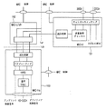
図1は従来及び本発明が適用される3GPP UTRANの構造を示した図である。
【0006】
図示されたように、UTRAN110は一つ以上の無線ネットワーク副システム(Radio Network Sub−systems;以下RNSと略称す)120、130で構成され、各RNS120、130は、一つのRNC121、131と、該RNC121、131によって管理される一つ以上の基地局(ノードB)(122、123)(130、133)とで構成される。そして、前記RNC121、131は、GSMネットワークとの回線交換通信を遂行するMSC(Mobile Switching Center)141に連結され、GPRS(General Packet Radio Service)ネットワークとパケット交換通信を遂行するSGSN(Serving GPRS Support Node)142に連結される。
【0007】
そして、基地局(ノードB)(122、123)(130、133)は、RNC121、131によって管理されて、アップリンクを通して端末150(例えば、移動局、使用者装置及び/または加入者ユニット)の物理階層に送る情報を受信し、ダウンリンクを通して端末150にデータを送信する。従って、基地局(ノードB)は、端末のためのUTRANの接続点(Access Point)の役割を担当するとみなすことができる。
【0008】
RNC121、131は、無線資源の割当及び管理を担当する。基地局(ノードB)を直接管理するRNCを制御RNC(Control RNC:CRNC)といい、前記CRNCは共用無線資源を管理する。その反面、担当RNC(Serving RNC:SRNC)は各端末に割り当てられた専用無線資源(Dedicated Radio Resources)を管理する。制御RNCと担当RNCは同様であるが、端末が担当RNCの領域を離脱して他のRNCの領域に移動する場合、制御RNCと担当RNCは異なることもあり得る。UMTSネットワーク内の多様な構成要素は、その物理的な位置が異なることもあるため、これらを連結させるインターフェース(Interface)が必要となる。基地局(ノードB)とRNCはIubインターフェースにより連結され、二つのRNCはIurインターフェースにより連結され、RNCとコアネットワークはIuインターフェースにより連結される。
【0009】
図2は、3GPP RAN規格に基づいて動作される端末とUTRAN間の無線接続インターフェースプロトコルの構造を示した図である。前記無線インターフェースプロトコルは、水平的に物理階層(PHY)、データリンク階層及びネットワーク階層で構成され、垂直的には制御情報を伝達するための制御平面(Control Plane)とデータ情報を伝送するための使用者平面(User Plane)とに区分される。前記使用者平面は、音声やIPパケットのような使用者のトラフィック情報が伝達される領域で、前記制御平面は、ネットワークインターフェースや呼の維持及び管理のような制御情報が伝達される領域である。
【0010】
図2で、各プロトコル階層は、通信システムで広く知られた開放型システム相互接続(Open System Interconnection;OSI)基準モデルの下位三つの階層に基づいて、第1階層(L1)、第2階層(L2)、第3階層(L3)に区分される。
【0011】
第1階層(L1)は、無線インターフェースのための物理階層(PHY:Physical Layer)として動作され、一つまたはそれ以上の伝送チャンネル(transport channel)を通して上位媒体接続制御(Medium Access Control;以下、MACと略称す)階層に接続される。物理階層は、伝送チャンネル(Transport Channel)を通して物理階層(PHY)に伝達されたデータを無線環境に適合した多様なコーディング及び変調方法などを利用して受信機に伝達する。物理階層(PHY)とMAC階層間に存在する伝送チャンネルは、端末により独占的に利用されるか、または様々な端末により共有されるかによって、専用伝送チャンネル(Dedicated Transport Channel)と共用伝送チャンネル(Common Transport Channel)とに区分される。
【0012】
第2階層(L2)は、データリンク階層(Data Link Layer)として動作され、様々な端末がWCDMAネットワークの無線資源を共有し得るようにする。前記第2階層(L2)は、MAC階層、無線リンク制御(Radio Link Control;以下、RLCと略称す)階層、パケットデータ収斂プロトコル(Packet Data Convergence Protocol;以下、PDCPと略称す)階層及び放送/マルチキャスト制御(Broadcast/Multicast Control;以下、BMCと略称す)階層に分けられる。
【0013】
前記MAC階層は、論理チャンネルと伝送チャンネル間の適切な対応(Mapping)関係を通してデータを伝達する。前記各論理チャンネルは、上位階層をMAC階層に連結するチャンネルであって、伝送される情報の種類によって多様な論理チャンネルが提供される。一般的に、制御平面の情報が伝送される場合は制御チャンネル(Control Channel)が使用され、使用者平面の情報が伝送される場合はトラフィックチャンネル(Traffic Channel)が使用される。前記MAC階層は、再び遂行する機能によって二つの副階層、即ち、SRNCに位置されて専用伝送チャンネルを管理するMAC−d副階層と、CRNCに位置されて共用伝送チャンネルを管理するMAC−c/sh副階層とに区分される。
【0014】
前記RLC階層は、上位階層から受信されたRLCサービスデータユニット(Service data uiut:SDU)の分割及び連結(Segmentation and Concatenation)機能により伝送に適合したRLCプロトコルデータユニット(protocol data unit:PDU)を形成し、伝送中、消失されたRLC PDUの再伝送を担当する自動反復要求(Automatic Repeat request;ARQ)機能を遂行することができる。前記RLC階層は、三つのモード、即ち、透過モード(Transparent Mode)、無応答モード(Unacknowledged Mode)、応答モード(Acknowledged Mode)の三つの方式で動作する。前記選択されたモードは、上位階層から受信されたRLC SDUを処理する方法に依存し、前記RLC階層には、上位階層から受信されたRLC SDUまたはRLC PDUを格納するためのRLCバッファーが存在する。
【0015】
前記PDCP階層は、RLC階層の上位階層であり、IPv4やIPv6のようなネットワークプロトコルを通して伝送される各データがRLC階層から伝送されるのに適合にさせる。この時、IPパケットの効率的な伝送のために、パケットのヘッダー情報を圧縮して伝送するヘッダー圧縮(Header Compression)技法が使用される。
【0016】
前記BMC階層は、CBS(Cell Broadcast Center)から伝達されたメッセージを無線インターフェースを通して伝送し得るようにする。BMCの主な機能は、端末に伝送されるセル放送メッセージ(Cell Broadcast Message)をスケジューリングして伝送することで、一般的に無応答モードで動作するRLC階層を通してデータを伝送する。
【0017】
前記PDCP階層とBMC階層はパケット交換方式を使用するためSGSNと連結され、使用者データのみを伝送するため使用者平面のみに位置する。前記PDCP階層及びBMC階層とは異なり、前記RLC階層は、上位階層に連結された階層によって、使用者平面に属することもあり、制御平面に属することもある。RLC階層が制御平面に属する場合、データは無線資源制御(Radio Resource Control;以下、RRCと略称す)階層から受信され、それ以外の場合は、RLC階層は使用者平面に属する。一般的に、第2階層(L2)により使用者平面から上位階層に提供される使用者データの伝送サービスは無線運搬者(Radio Bearer;RB)と定義され、第2階層(L2)により制御平面から上位階層に提供される制御情報の伝送サービスはシグナリング無線運搬者(Signaling Radio Bearer;SRB)と定義される。また、図2に示したように、RLC階層とPDCP階層の場合は、一つの階層内にいくつかのエンティティー(Entity)が存在する。これは、一つの端末が複数の無線運搬者(RB)を有し、通常一つまたは二つのRLCエンティティーとただ一つのPDCPエンティティーが一つの無線運搬者(RB)のために使用されるためである。前記RLC階層及びPDCP階層の各エンティティーは各階層で独立的な機能を遂行することができる。
【0018】
第3階層(L3)の最も下部に位置したRRC階層は制御平面のみで定義され、各無線運搬者(RB)の設定、再設定及び解除と関連されて、伝送チャンネル及び物理チャンネルを制御する。この時、無線運搬者が設定されるということは、特定のサービスを提供するために必要なプロトコル階層及びチャンネルの特性を規定し、それぞれの具体的なパラメーター及び動作方法を設定する過程を意味する。RRC階層は、RRCメッセージを通して上位階層で伝達される各制御メッセージの伝送も可能である。
【0019】
前記WCDMAシステムは、室内及びピコ(Pico−cell)セル環境では2Mbpsの送信速度を目標とし、一般的な無線環境では384kbpsの伝送速度を目標とする。しかし、無線インターネットが普遍化され、加入者数が増加するにつれて、より多様なサービスが提供され、このようなサービスを支援するために高速の伝送速度が必要になることと予想される。従って、現在の3GPPでは、WCDMAネットワークを発展させて高速の伝送速度を提供するための研究が進行されていて、その中、代表的なシステムとして高速ダウンリンクパケット接続(High Speed Downlink Packet Access:HSDPA)システムが知られている。
【0020】
前記HSDPAシステムは、WCDMAに基づいて、ダウンリンクで最大10Mbpsの速度を支援し、より短い遅延時間と向上された容量を提供し得ると予想される。向上された伝送速度と容量を提供するためにHSDPAシステムで適用された技術は、リンク適応技法(Link Adaptation;以下、LAと略称す)、ハイブリッド自動反復要求(Hybrid AutomaticRepeat request;以下、HARQと略称す)、迅速なセル選択(Fast Cell Selection;以下、FCSと略称す)、多重入力多重出力(Multiple Input Multiple Output;以下、MIMOと略称す)アンテナ技法などを考案することができる。
【0021】
リンク適応技法(LA)は、チャンネルの状態に合う変調及びコーディング方法(Modulation and Coding Scheme;以下、MCSと略称す)を使用することで、チャンネル状態が良い場合は16QAMと64QAMのような高度(high degree)の変調方法が使用され、チャンネル状態がよくない場合はQPSKのような低度(low degree)の変調方法が使用される。
【0022】
一般的に、低度の変調方法は、高度の変調方法に比べて伝送量は少ないが、チャンネル環境がよくない場合は優れた伝送成功率を示すため、フェーディング(Fading)や干渉の影響が大きい場合には有利である。その反面、高度の変調方法は、低度の変調方法と比較して周波数利用効率が遥かに優れていて、WCDMAの5MHz帯域幅を利用して10Mbpsの伝送速度を提供し得るようにする。しかし、雑音や干渉の影響に非常に敏感である。従って、端末が基地局と近い所に位置した場合は、16QAMや64QAMなどを使用して伝送効率を高めることができ、端末がセルの境界に位置したり、フェーディングの影響が大きい場合はQPSKのような低度の変調技法が有用である。
【0023】
HARQ方法は、RLC階層で使用される再伝送方法とは異なる概念の再伝送方法である。前記HARQ方法は物理階層と連携されて使用され、再伝送されたデータを以前の受信データと結合して、より高いデコーディング成功率を保障する。即ち、伝送に失敗したパケットが廃棄されるのではなく、格納され、該格納されたパケットはデコーディング以前の工程で再伝送パケットと結合されてデコーディングされる。従って、前記HARQ方法がLA技法と共に使用される場合、パケットの伝送効率を大幅に高めることができる。
【0024】
前記FCS方法は、既存のソフトハンドオーバーと類似の概念である。端末はいくつかのセルからデータを受信することができるが、各セルのチャンネル状態を考慮して、最もチャンネル状態が良いセルからデータの伝送を受けるようにする。既存のソフトハンドオーバーは、いくつかのセルからデータの伝送を受けて、ダイバーシティーを利用して伝送成功率を高める方法であったが、FCS方法は各セル間の干渉を減らすために、特定のセル一つからのみデータの伝送を受ける。
【0025】
前記MIMOアンテナ技法は、散乱が多く起きるチャンネル環境で、いくつかの独立的なチャンネルを利用してデータの伝送速度を向上させる方法である。普通、いくつかの送信アンテナといくつかの受信アンテナとで構成されて、アンテナ別に受信される各電波間の連関性を減らして、ダイバーシティーの利得を得ようとするシステムである。
【0026】
一方、HSDPAシステムは、既存のWCDMAネットワークに基づいて、WCDMAネットワークを最大限そのまま維持しながら新しい技術を導入しようとする。だが、新しい技術を導入するためには多少の修正が不回避である。代表的な例は、既存の基地局(Node B)機能を向上させた点である。即ち、WCDMAネットワークでは、ほとんどの制御器能がRNCに位置したが、より早くチャンネル状況に適応して、RNCまでの遅延時間を減らすためにHSDPAシステムのための新しい技術はほとんど基地局(Node B)で管理するようにする。しかし、基地局(Node B)の拡張された機能はRNCの代わりに遂行する機能でなく、RNCの立場で見ると、高速のデータ伝送のための機能が追加された補助機能を担当するとみなすことができる。
【0027】
従って、基地局(Node B)は、既存のWCDMAシステムとは異なり、MAC機能の一部を遂行するために修正され、これを遂行する階層をMAC−hs副階層と称す。
【0028】
前記MAC−hs副階層は、物理階層の上位に位置してパケットのスケジューリングやHARQ及びLA機能を遂行することができる。また、前記MAC−hs副階層は、HSDPAデータ伝送のために使用されるHS−DSCH(High Speed−Downlink Shared Channel)という新しい伝送チャンネルを使用する。このHS−DSCHチャンネルは、データがMAC−hs副階層と物理階層間で交換される時使用される。
【0029】
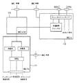
図3は、HSDPAシステムを支援するための無線インターフェースプロトコル構造を示した図である。図示されたように、MAC階層は、大きくMAC−d副階層、MAC−c/sh副階層及びMAC−hs副階層の三つの副階層に分けられる。前記MAC−hs副階層は基地局(Node B)の物理階層(PHY)上に位置し、MAC−c/shとMAC−d副階層は、従来のシステムのように、夫々CRNCとSRNCに位置する。また、HSDPAデータの伝達のために、HS−DSCH FP(Frame Protocol)という新しい伝送プロトコルがRNCと基地局(Node B)間または各RNC間で使用される。
【0030】
この時、MAC−hs副階層の上位に位置したMAC−c/sh副階層やMAC−d副階層、そしてRLC階層等は現在のシステムと同様な機能を遂行する。従って、HSDPAを支援するためのRNCは、現在のシステムで多少のソフトウェアのみを追加することで充分である。
【0031】
図4は、HSDPAシステムで使用されるMAC階層の構造を示した図である。
【0032】
図示されたように、MAC階層は、MAC−d副階層161、MAC−c/sh副階層162及びMAC−hs副階層163に区分される。前記MAC−d副階層161は、SRNCに位置して特定の端末のための各専用論理チャンネルを管理し、前記MAC−c/sh副階層162は、CRNCに位置して各共用伝送チャンネルを管理し、MAC−hs副階層163は、基地局(Node B)に位置してHS−DSCHを管理する。しかし、HSDPAシステムでMAC−c/sh副階層162が遂行する機能がほとんどないといえる。即ち、今までMAC−c/sh副階層162は、既存のシステムで様々な端末が共有する共用資源を割り当てて、これを処理する役割を担当したが、HSDPAシステムでは、単純にSRNCのMAC−d副階層161から伝達されたデータを基地局(Node B)のMAC−hs副階層163に伝達する流れ制御役割のみを遂行する。
【0033】
図4を参照して、RLC階層からのデータをMAC階層で如何なる処理過程を経てHS−DSCHに伝達するかに対して説明することにする。
【0034】
RLC階層から専用論理チャンネルのDTCH(Dedicated Traffic Channel)またはDCCH(Dedicated Control Channel)を通して伝達されたRLC PDUは、MAC−d階層でチャンネルスイッチング機能を通して経路が決定される。専用伝送チャンネル(DCH:Dedicated Channel)に伝送される場合は、MAC−d副階層161で関連ヘッダーが添付されて、DCH(Dedicated Channel)を通して物理階層に伝達され、HSDPAシステムのHS−DSCHチャンネルが使用される時、RLC PDUはチャンネルスイッチング機能によりMAC−c/sh副階層に送られる。複数の論理チャンネルが一つの伝送チャンネルを使用する時、RLC PDUは伝送チャンネル多重(multiplexing)ブロックを通過する。この過程中、各RLC PDUの属する論理チャンネルの識別(identification)情報(制御/トラフィックフィールド)が付加され、各論理チャンネルは優先順位(priority)を有し、論理チャンネルのデータは同様な優先順位を有する。
【0035】
MAC−d PDUが伝送される時、MAC−d副階層161は、MAC−dPDUの優先順位を伝送する。MAC−d副階層161からMAC−d PDUを受信したMAC−c/sh副階層162は、該当のMAC−d PDUを単純にMAC−hs副階層163に伝達する。前記MAC−hs副階層163に伝達されたMAC−d PDUはスケジューリングブロックの伝送バッファーに格納される。この時、一つの伝送バッファが各優先順位レベル毎に存在し、各MAC−hs SDU(MAC−d PDU)は、自身の優先順位に該当する伝送バッファーに順次格納される。
【0036】
次いで、スケジューリング機能(scheduling function)によりチャンネル状態に適合したデータブロックサイズが選択される。従って、データブロックは一つまたはそれ以上のMAC−hs SDUの結合で形成される。
【0037】
各データブロックには、優先順位識別子(priority class identifier)と送信シーケンスナンバー(Transmission sequence number)が付加され、該当のデータブロックはHARQブロックに伝達される。HARQブロックには、最大8つのHARQプロセスが存在する。スケジューリングブロックから受信されたデータブロックは適切なHARQプロセスに伝達される。各HARQプロセスは停止及び待機(stopand wait:SAW)ARQで動作する。この方法で、次のデータブロックは、現在のデータブロックが成功的に伝送されるまで伝送されない。前記のように、一つのTTIでは一つのデータブロックのみが伝送されるため、一つのHARQプロセスのみが一つのTTIで活性化される。
【0038】
他のHARQプロセスは順序になるまで待つ。各HARQプロセスはHARQプロセス識別子を有する。該当のHARQプロセス識別子は、ダウンリンク制御信号を通して予め端末機に知られ、特定のデータブロックは、送信機(UTRAN)と受信機(端末機)で同様なHARQプロセスを経ることになる。また、データブロックを伝送したHARQプロセスは、今後の再伝送を規定するためにデータブロックを格納する。端末からNACK(NonACKnowledge)が受信される時、データブロックを再伝送する。端末からACKが受信されると、HARQプロセスは該当のデータブロックを削除し、新しいデータブロックの伝送を準備する。データブロックが伝送されると、TFRC(transport format and resource combination)ブロックはHS−DSCHのための適切なTFCを選択する。
【0039】
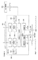
図5は、HSDPAシステムで使用されるMAC階層の構造を示した図である。MAC階層は、MAC−d副階層173、MAC−c/sh副階層172及びMAC−hs副階層171に分けられる。UTRANと異なり、前記三つの階層は同様な場所に位置する。端末にあるMAC−d副階層とMAC−c/sh副階層は、UTRANにあるMAC−d副階層及びMAC−c/sh副階層とほぼ同様であるが、前記MAC−c/hs副階層の場合、UTRANは送信のみを遂行し、端末は受信のみを遂行する点で多少異なる。
【0040】
以下、図5を参照して、MAC階層が物理的階層からデータを受信し、RLC階層に伝達する過程を説明する。HS−DSCHを通してMAC−hs副階層171に伝達されたデータブロックは、最初にHARQブロックにある様々なHARQプロセス中何れか一つのHARQプロセスに格納される。この時、前記データブロックが如何なるプロセスに格納されるかは、ダウンリンク制御信号に含まれたHARQプロセス識別子により知ることができる。
【0041】
データブロックが格納されるHARQプロセスは、もしデータブロックにエラーがあると、NACK情報をUTRANに伝送してデータブロックの再伝送を要求し、エラーがないと、データブロックを再整理(Reordering)バッファーに伝達し、UTRANにACK情報を伝送する。再整理バッファーは、UTRANの送信バッファーと同様な優先順位を有している。HARQプロセスは、データブロックに含まれた優先順位識別子を通してデータブロックを再整理バッファーに伝達する。再整理バッファーの大きな特性は、データの順次的な伝送を支援する点にある。
【0042】
各データブロックは、送信シーケンスナンバー(transmission sequence number:TSN)に基づいて順次的に上位階層に伝達される。より詳細に説明すると、一つまたはそれ以上の以前のデータブロックが遺失された時、データブロックが受信されると、前記データブロックは再整理バッファーに格納され、上位階層には伝送されない。次いで、以前のデータブロックが受信されて上位階層に伝達された時のみ前記データブロックは上位階層に伝達される。いくつかのHARQプロセスが動作されるため、再整理バッファーは非順次的にデータブロックを受信することができる。従って、各データブロックが順次的に上位階層に伝達されるように、順次伝達機能が再整理バッファーのために使用される。
【0043】
端末機の再整理バッファーとUTRANの伝送バッファーとの差異点は、再整理バッファーは一つまたはそれ以上のMAC−hs SDUsで構成されたデータブロック単位でデータを格納し、伝送バッファーはMAC−has SDU(=MAC−d PDU)の単位でデータを格納する点である。MAC−d副階層173は、MAC−d PDU単位でデータを処理するため、端末のMAC−hs副階層171の再整理バッファーがデータブロックをMAC−d副階層173に伝達する場合、再整理バッファーは、まずデータブロックを各MAC−d PDUに分解して伝達する。MAC−c/sh副階層172は、MAC−hs副階層171から受信した各MAC−d PDUをそのままMAC−d副階層173に伝達し、MAC−d副階層173は、伝送チャンネル多重化ブロックで各MAC−d PDUに含まれた論理チャンネル識別子(C/Tフィールド)を検査した後、各MAC−d PDUに対応する論理チャンネルを通してRLCに伝達する。
【0044】
図6はHSDPAシステムでデータブロックを送受信するためのプロセスを示した図である。実際に各MAC−d PDUは送信バッファー160に格納されているが、便宜上、データブロック(=一つまたはそれ以上のMAC−d PDU)で示した。また、各データブロックの大きさは変わることもあるが、図面上では同様に示した。また、8つのHARQプロセス(181−188)が存在することと仮定した。
【0045】
前記プロセスは、伝送バッファーにあるTSN=13からTSN=22までの各データブロックを受信機に伝送することを示している。低いTSNを有するデータブロックから空のHARQプロセスに伝達される。例えば、TSN=13のデータブロックはHARQプロセス#1 181に伝達され、TSN=14のデータブロックはHARQプロセス#8に伝達される。このような説明から、TSNはHARQプロセス番号と関連がないということが分かる。
【0046】
HARQプロセスが任意のデータブロックを受信すると、HARQプロセスは特定のTTIから受信機に前記データブロックを伝送し、該当のデータブロックを後で行われる再伝送のために格納する。特定のTTIでは、ただ一つのデータブロックのみが伝送されるため、一つのTTIでただ一つのHARQプロセスのみが活性化される。データブロックを伝送したHARQプロセスは、自身の前記データブロック番号を前記データブロックとは異なるチャンネルに伝送されるダウンリンク制御信号を通して受信機に知らせる。
【0047】
送信機と受信機のHARQプロセスを一致させる理由は、各HARQプロセスペア(pair)により停止及び待機(stop−and−wait:SAW)ARQ方法が使用されるためである。即ち、TSN=13のデータブロックを伝送したHARQプロセス#1 181はそのデータブロックが成功的に伝送されるまで他のデータブロックを伝送しない。受信機のHARQプロセス#1 191は、該当のTTIの間、ダウンリンク制御信号を通してデータが伝達されたことがわかるため、決められたTTI(transmission time interval)内にデータブロックが成功的に受信されない場合、アップリンク制御信号を通してNACK情報を送信機に伝送する。その反面、データブロックが成功的に受信されると、受信機のHARQプロセス#1は送信機にACK情報を伝送し、それと同時に、優先順位によって該当のデータブロックを再整理バッファーに伝達する。
【0048】
再整理バッファーは優先順位レベル(priority level)毎に存在する。HARQプロセスは、データブロックのヘッダー情報に含まれた優先順位を検査した後、優先順位によってデータブロックを再整理バッファーに伝達する。次いで、すべての以前のデータブロックが上位階層に伝達された時、前記データブロックは上位階層に伝達される。然し、一つまたはそれ以上の以前のデータブロックが上位階層に伝達されない場合、前記データブロックは再整理バッファー190に格納される。即ち、再整理バッファーは、上位階層へのデータブロックの順次伝送を支援しなければならなく、上位階層に伝達されないデータブロックは再整理バッファーに格納される。
【0049】
図6は、TSN=14のデータブロックが受信された時、TSN=13のデータブロックは受信されない状態で、TSN=14のデータブロックがTSN=13のデータブロックが受信されるまで再整理バッファーに格納されることを示している。TSN=13のデータブロックが受信されると、二つのデータブロックのすべてがTSN=13とTSN=14の順序によって上位階層に伝達される。各データブロックが上位階層に伝達される時、各データブロックはMAC−d PDU単位で分割されて伝達される。
【0050】
【発明が解決しようとする課題】
然るに、前記再整理バッファーは、少なくとも一つの欠点を有している。再整理バッファーが各データブロックの順次伝送を支援するため、特定のデータブロックが受信されない場合、後でTSNを有する各データブロックは上位階層に伝達されなく、再整理バッファーに格納される。特定のデータブロックが長時間または永久的に受信されないと、再整理バッファーにある各データブロックは上位階層に伝達されなくなる。その上、短い時間の周期後、前記バッファーがぎっしり満たされるため、追加的なデータブロックも受信されることができなく、よって、交錯(stall)状況が招来される。
【0051】
交錯状況が発生して、特定のデータブロックが長時間または永久的に受信されないと、HSDPAシステムの伝送効率が悪化される。より詳細に説明すると、一つの遺失された(missing)データブロックにより、複数のデータブロックが長時間MAC−hsのバッファー内に格納されて残る場合、全体システムのデータ伝送効率が低くなる。これは、高速データ通信を提供することのような多くのHSDPAシステムの長所を損傷させる。
【0052】
下記の二つの理由中何れか一つによって、データブロックが永久的に受信されない。
【0053】
1)UTRANが端末が送ったNACK信号をACK信号に誤って判断した場合
2)データブロックがシステムにより許容される最大回数だけ再伝送されるか、決められた時間の間伝送が成功的に遂行されず、UTRANのHARQプロセスがデータブロックを廃棄した場合
1)の場合は、端末が送った状態情報をUTRANが誤ってデコーディングしたケースで、2)の場合は、特定のデータブロックが長時間の間成功的に伝送されなかったため、UTRANが前記特定のデータブロックを廃棄したケースである。然し、UTRANは廃棄事実を端末に知らせない。この場合、データブロックは永久的に伝送されないため、以後のデータブロックは、上位階層に伝送されないまま、続けて再整理バッファーに格納される状態で残るようになる。よって、プロトコルが交錯状況になるという不都合な点があった。
【0054】
従って、移動通信システムにおいて、通信受信機の再整理バッファーの交錯状況を正すと共に、音声とデータ伝送効率を高めるための方法が要求される。
【0055】
本発明は、このような従来の課題に鑑みてなされたもので、移動通信システムにおける通信の質を向上し得るシステム及びその方法を提供することを目的とする。
【0056】
又、使用者端末における交錯状況を防止して前述した目的を達成すると共に、システムの送信効率を向上させることを目的とする。
【0057】
又、受信機の再整理バッファーに格納された各時間データブロックの量を制限する交錯タイマーを使用することで、前述した目的を達成することを目的とする。
【0058】
又、バッファーに格納されたデータブロックに割当された送信シーケンスナンバーに対してラップ−アラウンド条件が発生することを防止する値により交錯タイマーの周期を設定することを目的とする。
【0059】
又、再整理バッファーで交錯状況を防止すると同時に、正確に受信されてバッファーに格納された各データブロックが遺失されることを防止し得るシステム及びその方法を提供することを目的とする。
【0060】
【課題を解決するための手段】
本発明の通信システムの受信機におけるパケットデータ処理方法は、シーケンスナンバーを有するデータブロックを受信する工程と、再整理バッファーに前記データブロックを格納する工程と、先行シーケンスナンバーのデータブロックが遺失され、前記タイマーが非活性であると、前記再整理バッファーのためのタイマーを稼動する工程とを順次行うことを特徴とする。
【0061】
本発明の通信システムの受信機におけるパケットデータ処理方法は、前記タイマーは、前記再整理バッファーの制御のために提供された唯一のタイマーであることを特徴としてもよい。
【0062】
本発明の通信システムの受信機におけるパケットデータ処理方法は、前記タイマーが稼動された後、少なくとも一つの追加データブロックを受信する工程と、該データブロックが予想された遺失データブロック中、最も低いシーケンスナンバーのデータブロックでないと、前記少なくとも一つの追加データブロックを再整理バッファーに格納する工程とを更に行うことを特徴としてもよい。
【0063】
本発明の通信システムの受信機におけるパケットデータ処理方法は、前記追加データブロックが、前記タイマーの稼動時に格納されたデータブロックのシーケンスナンバーに先行するシーケンスナンバーのデータブロックであると、タイマーが終了される時、再整理バッファーから追加データブロックを除去する工程を更に行うことを特徴としてもよい。
【0064】
本発明の通信システムの受信機におけるパケットデータ処理方法は、前記追加データブロックを上位階層に伝達する工程を更に行うことを特徴としてもよい。
【0065】
本発明の通信システムの受信機におけるパケットデータ処理方法は、前記追加データブロックが、前記タイマーの稼動時に格納されたデータブロックのシーケンスナンバーに先行するシーケンスナンバーのデータブロックで、二つのデータブロック間の全てのデータブロックが受信されると、タイマーが終了される時、再整理バッファーから追加データブロックを除去する工程を更に行うことを特徴としてもよい。
【0066】
本発明の通信システムの受信機におけるパケットデータ処理方法は、前記追加データブロックを上位階層に伝達する工程を更に行うことを特徴としてもよい。
【0067】
本発明の通信システムの受信機におけるパケットデータ処理方法は、再整理バッファーのためにタイマーを稼動する工程と、シーケンスナンバーを有するデータブロックを受信する工程と、前記データブロックを再整理バッファーに格納する工程と、前記データブロックのシーケンスナンバーが、前記タイマーの稼動時に受信され、再整理バッファーに格納されたデータブロックのシーケンスナンバーに先行すると、前記データブロックを再整理バッファーから除去する工程とを順次行うことを特徴とする。
【0068】
本発明の通信システムの受信機におけるパケットデータ処理方法は、前記データブロックのシーケンスナンバーが、タイマーの稼動時に受信され、前記再整理バッファーに格納されたデータブロックのシーケンスナンバーに先行すると、前記タイマーの終了時に前記受信工程で受信されたデータブロックを伝達する工程を更に行うことを特徴としてもよい。
【0069】
本発明の通信システムの受信機におけるパケットデータ処理方法は、前記タイマーの稼動時に受信されて前記再整理バッファーに格納されたデータブロックを、前記タイマーの終了時に上位階層に伝達する工程を更に行うことを特徴としてもよい。
【0070】
本発明の通信システムの受信機におけるパケットデータ処理方法は、前記データブロックのシーケンスナンバーが、前記タイマーの稼動時に受信されて、前記再整理バッファーに格納されたデータブロックのシーケンスナンバーに連続的に後続すると、前記タイマーの終了時に前記データブロックを再整理バッファーから除去する工程を更に行うことを特徴としてもよい。
【0071】
本発明の通信システムの受信機におけるパケットデータ処理方法は、前記データブロックのシーケンスナンバーが、前記タイマーの稼動時に受信されて、前記再整理バッファーに格納されたデータブロックのシーケンスナンバー以後に来るが、連続的に後続しないと、前記タイマーの終了後、前記受信工程で受信されたデータブロックの格納を続ける工程を更に行うことを特徴としてもよい。
【0072】
本発明の通信システムの受信機におけるパケットデータ処理方法は、前記タイマーの終了後、再整理バッファーで最も高いシーケンスナンバーを有するデータブロックを決定する工程を更に行うことを特徴としてもよい。
【0073】
本発明の通信システムの受信機におけるパケットデータ処理方法は、前記最も高いシーケンスナンバーを有するデータブロックのために、前記タイマーを再稼動する工程を更に行うことを特徴としてもよい。
【0074】
本発明の無線通信の使用者端末機は、シーケンスナンバーを有するデータブロックを格納するための再整理バッファーと、タイマーと、受信されたデータブロックのシーケンスナンバーに先行するシーケンスナンバーの他のデータブロックが遺失され、前記タイマーが非活性であると、前記再整理バッファーのために前記タイマーを稼動させる制御器と、を含んで構成されることを特徴とする。
【0075】
本発明の無線通信の使用者端末機は、前記タイマーは、前記再整理バッファーを制御するために提供された唯一のタイマーであることを特徴としてもよい。
【0076】
本発明の無線通信の使用者端末機は、前記制御器は、
前記タイマーの稼動後、少なくとも一つの追加データブロックを受信するように制御して、前記データブロックが予想遺失データブロック中最も低いシーケンスナンバーのデータブロックでないと、前記少なくとも一つの追加データブロックを再整理バッファーに格納するように制御することを特徴としてもよい。
【0077】
本発明の無線通信の使用者端末機は、前記再整理バッファーは、もし前記追加データブロックが、前記タイマーの稼動時に格納されたデータブロックのシーケンスナンバーに先行するシーケンスナンバーのデータブロックであると、前記タイマーの終了時、追加データブロックを再整理バッファーから除去することを特徴としてもよい。
【0078】
本発明の無線通信の使用者端末機は、前記制御器は、追加データブロックが上位階層に伝達されるように制御することを特徴としてもよい。
【0079】
本発明の無線通信の使用者端末機は、前記制御器は、もし前記追加データブロックが前記タイマーの稼動時に格納されたデータブロックのシーケンスナンバーに先行するシーケンスナンバーのデータブロックで、二つのデータブロック間の全てのデータブロックが受信されると、前記タイマーの終了時、追加データブロックを再整理バッファーから除去するように制御することを特徴としてもよい。
【0080】
本発明の無線通信の使用者端末機は、前記制御器は、追加データブロックが上位階層に伝達されるように制御することを特徴としてもよい。
【0081】
本発明の通信システムの受信機におけるパケットデータ処理方法は、シーケンスナンバーを有するデータブロックを受信する工程と、先行シーケンスナンバーのデータブロックが遺失され、タイマーが非活性であると、再整理バッファーのための満了周期を有するタイマーを稼動する工程と、前記データブロックを前記再整理バッファーに格納する工程とを順次行うことを特徴とする。
【0082】
本発明の通信システムの受信機におけるパケットデータ処理方法は、他のデータブロックを受信する工程と、前記データブロックが予想遺失データブロック中最も低いシーケンスナンバーのデータブロックでないと、前記データブロックを再整理バッファーに格納する工程と、を更に行うことを特徴としてもよい。
【0083】
本発明の通信システムの受信機におけるパケットデータ処理方法は、他のデータブロックを受信する工程と、前記データブロックが予想遺失データブロック中最も低いシーケンスナンバーのデータブロックであると、前記データブロックを再整理バッファーに格納せず上位階層に伝達する工程と、を更に行うことを特徴としてもよい。
【0084】
本発明の通信システムの受信機におけるパケットデータ処理方法は、前記バッファーに格納されたデータブロックに連続するデータブロックを上位階層に伝達する工程と、上位階層に伝達された各データブロックをバッファーから削除する工程と、を更に行うことを特徴としてもよい。
【0085】
本発明の通信システムの受信機におけるパケットデータ処理方法は、前記タイマーの終了前に、先行シーケンスナンバーの全てのデータブロックが受信されると、前記タイマーを停止させる工程を更に行うことを特徴としてもよい。
【0086】
本発明の通信システムの受信機におけるパケットデータ処理方法は、前記タイマーの稼動時に受信されて格納されたデータブロックに連続する格納された各データブロックを上位階層に伝達する工程を更に行うことを特徴としてもよい。
【0087】
本発明の通信システムの受信機におけるパケットデータ処理方法は、前記バッファーに少なくとも一つのデータブロックが残っていると、前記タイマーを再び稼動する工程を更に行うことを特徴としてもよい。
【0088】
本発明の通信システムの受信機におけるパケットデータ処理方法は、前記タイマーの稼動時に前記バッファーで最も高いシーケンスナンバーのデータブロックが前記タイマーの終了前に上位階層に伝達されると、前記タイマーを停止させる工程を更に行うことを特徴としてもよい。
【0089】
本発明の通信システムの受信機におけるパケットデータ処理方法は、再整理バッファーのためのタイマーが非活性であると、前記再整理バッファーにあるデータブロックをチェックする工程と、前記再整理バッファーに少なくとも一つのデータブロックが残っていると、前記再整理バッファーに格納されたデータブロック中最後に上位階層に伝達されるデータブロック中何れか一つのために前記タイマーを再稼動する工程と、を行うことを特徴とする通信システムの受信機におけるパケットデータ処理方法。
【0090】
本発明の通信システムの受信機におけるパケットデータ処理方法は、前記データブロック中何れか一つは、前記再整理バッファーに格納された最も高いシーケンスナンバーを有するデータブロックに該当することを特徴としてもよい。
【0091】
本発明の通信システムの受信機におけるパケットデータ処理方法は、データブロックを受信する工程と、前記データブロックを再整理バッファーに格納する工程と、前記再整理バッファーのためのタイマーを稼動する工程と、前記タイマーの終了時、前記データブロックを再整理バッファーから上位階層に伝達する工程と、を順次行い、前記伝達工程は、非順次的にデータブロックを伝達する工程を行うことを特徴とする。
【0092】
本発明の通信システムの受信機におけるパケットデータ処理方法は、前記非順次伝達は、各データブロックのシーケンスナンバーに基づくことを特徴としてもよい。
【0093】
本発明の通信システムの受信機におけるパケットデータ処理方法は、非順次伝達は、前記データブロックに先行する一つ以上の遺失データブロックを有する場合、前記データブロックの伝達に該当することを特徴としてもよい。
【0094】
前記各データブロックに先行する一つ以上の遺失データブロックを有する各データブロックは、それらデータブロックのシーケンスナンバーに基づいて順次的に上位階層に伝達されることを特徴としてもよい。
【0095】
このような目的を達成するため、本発明に係る使用者端末における交錯状況の防止方法においては、データブロックSNを受信する工程と、該データブロックSNの送信シーケンスナンバーに先行する送信シーケンスナンバーを有するデータブロックが受信されなかったことを感知する工程と、再整理バッファーに前記データブロックSNを格納する工程と、タイマーの第1周期が終了される時、前記バッファーからデータブロックSNを出力する工程と、を順次行うことを特徴とする。又、前記使用者端末は、例えば、高速ダウンリンクパケット−接続(HSDPA)移動通信システムの中で動作するように構成し得るし、前記再整理バッファーは、端末のMAC階層に具現されることが好ましい。若し、このような方法により具現されると、前記バッファーは、HS−DSCHチャンネルを経由して物理階層から各データブロックを受信し得るし、それらデータブロックは、RLC階層のような上位階層に出力することができる。
【0096】
又、本発明に係る使用者端末における交錯状況の防止方法の付加的な工程は、第1タイマー周期の間、前記先行データブロックを受信する工程と、該先行データブロック及びデータブロックSNを上位階層に伝達する工程と、を順次行うことを特徴とする。又、前記先行データブロックは、多様な方法中の一つにより伝達されることができる。又、本発明に係る使用者端末における交錯状況の防止方法の実施形態においては、前記先行データブロック及びデータブロックSNは、第1タイマー周期が終了される時、意図された目的地に伝達し得ることを特徴とする。有効に、この工程は、先行送信シーケンスナンバーを有する少なくとも一つの他のデータブロックが受信されない場合にも遂行されることができる。
【0097】
又、本発明に係る使用者端末における交錯状況の防止方法の他の実施形態においては、若し、前記先行データブロックが前記第1タイマー周期が終了される前に受信され、前記先行データブロックがデータブロックSNに先行する唯一の遺失データブロックであると、前記先行データブロック及びデータブロックSNは、意図された目的地に伝達され、前記タイマーは停止することを特徴とする。
【0098】
又、本発明に係る使用者端末における交錯状況の防止方法の又他の実施形態においては、先行送信シーケンスナンバーを有する複数のデータブロックは、データブロックSNが受信された時に遺失されたと感知されることを特徴とする。この場合、第1タイマーが終了される前に少なくとも一つの先行データブロックが受信された時、若し、該当ブロックに先行する遺失データブロックが予想されないと、前記受信された先行データブロックは、直ちに意図された目的地に伝達されることを特徴とする。そうでないと、前記受信された先行データブロックは、第1タイマーが終了された後にデータブロックSNと共に伝達されることを特徴とする。
【0099】
又、本発明に係る使用者端末における交錯状況の防止方法の又他の実施形態においては、連続された送信シーケンスナンバーを有するデータブロックが第1タイマー周期の間受信されることを特徴とする。次いで、データブロックSNと前記次のデータブロックは、前記第1タイマー周期が終了される時(然し、前記連続されたデータブロックとデータブロックSNとが連続的な送信シーケンスナンバーを有する場合のみに)、意図された目的地に伝達されることを特徴とする。
【0100】
又、本発明に係る使用者端末における交錯状況の防止方法の又他の実施形態においては、連続された送信シーケンスナンバーを有するデータブロックが第1タイマー周期の間に受信されることを特徴とする。このような場合、前記先行データブロック及びデータブロックSNは、第1タイマー周期が終了される時に意図された目的地に伝達され、前記連続されたデータブロックも前記第1タイマー周期が終了される時(然し、データブロックSNと前記次のデータブロックとが連続的な送信シーケンスナンバーを有する場合のみに)、意図された目的地に伝達されることを特徴とする。
【0101】
又、本発明に係る使用者端末における交錯状況の防止方法の又他の実施形態においては、連続された送信シーケンスナンバーを有する複数のデータブロックが前記第1タイマー周期の間に受信されることを特徴とする。この場合、前記連続された各データブロックは、前記第1タイマー周期が終了される時(然し、データブロックSNと前記複数の連続データブロックとが連続的な送信シーケンスナンバーを有する場合のみに)、データブロックSNと共に意図された目的地に伝達されることを特徴とする。
【0102】
又、本発明に係る使用者端末における交錯状況の防止方法の又他の実施形態においては、連続された送信シーケンスナンバーを有する複数のデータブロックが前記第1タイマー周期の間に受信され、それら複数の連続されたデータブロック中、少なくとも一つの遺失データブロックMが存在すると感知されることを特徴とする。又、データブロックSNと一つ以上の連続された各ブロックとは、連続的な送信シーケンスナンバーを有することができるし、遺失データブロックMは、データブロックSNの送信シーケンスナンバーを連続して続く一つ以上の連続された各データブロックの送信シーケンスナンバー以後の送信シーケンスナンバーを有することができることを特徴とする。この場合、データブロックSNの送信シーケンスナンバーを連続して続く送信シーケンスナンバーを有する一つ以上のデータブロックは、前記第1タイマー周期が終了される時に意図された目的地に伝達されることを特徴とする。次いで、該伝達された各データブロックは、バッファーから廃棄されて残りの一連の各データブロック(すなわち、データブロックMの送信シーケンスナンバー以後の送信シーケンスナンバーを有するブロック)は、バッファーに格納されることを特徴とする。
【0103】
又、本発明に係る使用者端末における交錯状況の防止方法の又他の実施形態においては、前記タイマーの第2周期は、最も高い送信シーケンスナンバーを有する残りの連続された各ブロックに基づいて稼働し得ることを特徴とする。この場合、残りの連続された各ブロックは、該当ブロックに先行する予想された全ての遺失データブロックが受信された後、又は前記第2タイマー周期が終了された後に意図された目的地に伝達されることを特徴とする。
【0104】
又、本発明は、本発明に係る使用者端末における交錯状況の防止方法の実施形態に包含された工程を遂行する各コード部を有するコンピュータプログラムであることを特徴とする。該コンピュータプログラムは、使用者端末機で支援可能なコンピュータ言語により作成し得るし、永久的又は削除可能なコンピュータ−判読可能媒体内に記録されることができるし、又、端末機にインターフェースされることができることを特徴とする。
【0105】
又、本発明は、再整理バッファーを制御するための方法である。好ましくは、前記バッファーは、通信受信機内に位置するが、必要によって通信システムの他の位置に具現し得ることを特徴とする。該方法は、バッファーにある各データブロックの格納を制御するタイマーを提供する工程と、前記データブロックに割当された送信シーケンスナンバーのラップ−アラウンドの発生を防止する値により前記タイマーの周期を設定する工程と、を順次行うことを特徴とする。
【0106】
又、本発明に係る使用者端末における交錯状況の防止方法の又他の実施形態においては、通信システムの受信機におけるパケットデータを処理するための方法は、シーケンスナンバーを有するデータブロックを受信する工程と、前記データを再整理バッファーに格納する工程と、先行シーケンスナンバーのデータブロックが遺失されると、前記再整理バッファーのためのタイマーを稼動させる工程と、を順次行うことを特徴とする。この時、前記タイマーは、前記再整理バッファーを制御するために提供された唯一のタイマーであって、好ましくは、前記タイマーは、前記各先行シーケンスナンバーのデータブロックが遺失されて前記タイマーが非活性化された時のみに稼働されることを特徴とする。
【0107】
又、本発明に係る使用者端末における交錯状況の防止方法の実施形態の付加的な各工程は、前記データブロックが直ちに上位階層に伝達されることができるかを決定する工程を包含することを特徴とする。若し、直ちに伝達されることができる場合、前記データブロックは、前記再整理バッファーに格納されることなく、上位階層に伝達され、直ちに伝達されることができない場合、前記データブロックは再整理バッファーに格納されることを特徴とする。又、前記タイマーが活性状態であるかを決定する工程は、稼動工程以前に遂行されることができる。若し、前記タイマーが活性状態であると、前記稼動工程は遂行されないことがある。
【0108】
又、本発明の付加的な各工程は、前記タイマーが稼働された後、少なくとも一つの追加データブロックを受信する工程と、該少なくとも一つの追加データブロックを前記再整理バッファーに格納する工程と、を順次行うことを特徴とする。又、前記追加データブロックは先行シーケンスナンバーを有する。この場合、前記追加データブロックは、バッファーから除去されることができるし、該当ブロックに先行する予想遺失データブロックが存在しないか、又は前記タイマーが終了される時に前記追加データブロックは上位階層に伝達されることができることを特徴とする。又、前記追加データブロックは、連続されたシーケンスナンバーを有することができることを特徴とする。この場合、前記追加データブロックは、バッファーから除去されることができるし、若し、追加データブロックの連続されたシーケンスナンバーが前記シーケンスナンバーを有するデータブロックに連続的に続くと、タイマーが終了される時に上位階層に伝達されることを特徴とする。若し、追加データブロックのシーケンスナンバーが連続的に後続しないと、前記追加ブロックは、タイマーが終了された後に前記バッファーに継続して格納されることができるし、前記タイマーは、バッファーにおける最も高いシーケンスナンバーを有するバッファーに格納されたデータブロックのために再稼働されることができることを特徴とする。
【0109】
又、本発明に係る使用者端末における交錯状況の防止方法の又他の実施形態においては、通信システムの受信機におけるパケットデータの処理方法は、再整理バッファーのためのタイマーを稼動する工程と、シーケンスナンバーを有するデータブロックを受信する工程と、前記データブロックを再整理バッファーに格納する工程と、若し、前記データブロックのシーケンスナンバーがタイマーが稼働する時に受信されて再整理バッファーに格納されたデータブロックのシーケンスナンバーに先行すると、前記タイマーが終了される時に前記データブロックを再整理バッファーから除去する工程と、を順次行うことを特徴とする。
【0110】
又、本発明に係る使用者端末における交錯状況を防止するシステムにおいては、シーケンスナンバーを有するデータブロックを格納するための再整理バッファーと、タイマーと、先行シーケンスナンバーのデータブロックが遺失されると、前記再整理バッファーのためのタイマーを稼動させる制御器と、を包含して構成された使用者端末機を提供する。又、前記タイマーは、再整理バッファーを制御するために提供された唯一のタイマーであって、前記制御器は、先行シーケンスナンバーのデータブロックが遺失されて前記タイマーが非活性であると、前記タイマーを稼動させることを特徴とする。又、前記制御器は、先行シーケンスナンバーのデータブロックが直ちに上位階層に伝達されることができるかを決定し得ることを特徴とする。又、前記バッファーは、データブロックが直ちに上位階層に伝達されることができないと、前記先行シーケンスナンバーのデータブロックを再整理バッファーに格納することを特徴とする。若し、データブロックが直ちに伝達されることができると、バッファーは、前記ブロックを上位階層に出力することを特徴とする。
【0111】
又、前記再整理バッファーは、タイマーが稼働する時に少なくとも一つの追加データブロックを前記再整理バッファーに格納する。前記追加データブロックは、先行シーケンスナンバーを有する遺失データブロックでありうる。若し、そうであると、前記追加ブロックは、再整理バッファーから除去されて前記タイマーが終了される時に上位階層に伝達されることを特徴とする。又、前記追加データブロックは、連続されたシーケンスナンバーでありうる。若し、そうであると、前記データブロックは、再整理バッファーから除去されて前記データブロックの連続されたシーケンスナンバーが前記シーケンスナンバーを有するデータブロックを順次的に続くと、前記タイマーが終了される時に再整理バッファーから上位階層に伝達されることを特徴とする。
【0112】
又、前記再整理バッファーは、若し、追加データブロックの連続されたシーケンスナンバーが前記シーケンスナンバーを有するデータブロックを順次的に続かないと、タイマーが終了された後、前記追加データブロックを格納することを続ける。この場合、前記制御器は、バッファーにおける最も高いシーケンスナンバーを有するデータブロックを決定した後、前記タイマーを再稼働させることを特徴とする。
【0113】
又、本発明に係る使用者端末における交錯状況の防止方法の又他の実施形態においては、通信システムの受信機におけるパケットデータの処理方法は、データブロックを受信する工程と、前記データブロックを再整理バッファーに格納する工程と、前記再整理バッファーのためのタイマーを稼動する工程と、前記タイマーが終了される時、前記データブロックを再整理バッファーから上位階層に伝達する工程と、を順次行うことを特徴とする。該実施形態においては、前記伝達工程の前記データブロックは、順次的に(sequentially)伝達されるが、順次(in−sequence)方法でないことがあることを特徴とする。
【0114】
又、順次的な伝達と順次伝達との差は、この場合、隣接して伝達された二つのデータブロックのシーケンスナンバーが連続的でないことがあることを意味する。即ち、遺失データブロックが前記伝達された各データブロック間にあることがある。
【0115】
例えば、伝達された各データブロックが次のようなシーケンスナンバーを有する。
【0116】
14、15、17、19、24、25、26、28、....→遺失データブロックが存在するが、順次的に伝達されなければならない。
【0117】
若し、前記例に順次伝達を適用すると、16より高いシーケンスナンバーの各データブロックは、データブロック16が伝達されるまでに伝達されるといけない。又、該伝達された各データブロックのシーケンスナンバーは、次のようでなければならない。
【0118】
14、15、16、17、18、19、....→遺失データブロックが存在するが、順次的に伝達されなければならない。
【0119】
反面、再整理バッファーは、非順次的なデータブロックを受信することができる。この場合、前記非順次(out−of−sequence)受信は、再整理バッファーが下位TSNを有する各データブロックより一層早く上位TSNを有するデータブロックを受信し得ることを意味する。例えば、再整理バッファーは、次のように各データブロックを受信する。
【0120】
15、20、14、16、23、24、17、18、......
本発明は、通信システムにおける交錯状況を防止する従来の方法に比べて相当に向上されたシステム及びその方法を提供する。従来のシステムにおいては、遺失される受信された各データブロックを、本発明のシステムにおいては、正確に伝達することで、伝送効率及び受信機の通信の質を向上し得ることを特徴とする。又、本発明は、受信機におけるTSNラップ−アラウンドを起こす累積遅延問題を除去し得ることを特徴とする。従って、本発明は、このような向上によって次世代無線システムが要求する性能基準を充足又は超過し得ることを特徴とする。
【0121】
【発明の実施の形態】
本発明は、移動通信システムの使用者端末における交錯状況を回避するためのシステムと方法を提示する。本発明は、好ましくは、3GPPにより開発されたUMTS(universal mobile telecommunications system)のような移動ネットワークで具現される。然し、本発明は他の基準による移動通信システムにも適用される。また、本発明は、また交錯状況を未然に防止し得る方法を具現する使用者端末に関するものである。また、本発明に係る方法を具現するための使用者端末に格納されるコンピュータプログラムに関するものである。以下、本発明の実施の形態に対して説明する。
【0122】
本発明は、HSDPA(high−speed downlink packet−access)移動通信システムのためのものである。このような形態のシステムは、無線リンクを通してUTRANと通信する使用者装置を含んでいる。前記使用者装置は、例えば、移動電話機、個人携帯装置(personal digital assistant:PDA)、ポケットPC、ラップトップまたはノートブックコンピュータ、及び他の装置、即ち、移動通信ネットワークを通して無線で伝送された各信号を受信する装置を含むことができる。前記したように、これら信号はUTRANを通して送信されることもできるし、図1〜3、5、6に示されたプロトコル構造によって動作する使用者端末により受信されることもできる。
【0123】
このような方式で具現される時、本発明に係る方法は、データブロックの格納と以後の伝送、及び使用者端末のMAC階層内で動作する再整理バッファーからのデータブロック削除を制御する。より詳しくは、再整理バッファーは、下位レベルの物理階層から各データブロックを受信し、前記各ブロックを夫々MAC−c/shとMAC−d副階層を通してRLC階層のような上位階層に伝送するMAC−hs副階層に位置することができる。このような特性は、図5を参照して詳細に説明されたため、詳細な説明は省略する。
【0124】
図7は本発明の好ましい携帯に係る使用者端末を示した図である。前記端末は、以下で説明する方法を実行するための各回路とソフトウェアを含んでいる。このような回路とソフトウェアは複数の高速ダウンリンク共有チャンネル(high−speed downlink shared channels:HS−DSCHs)302を通してUTRANのピアエンティティー(peer entity)から各データブロックを受信し、それらデータブロックを一連の各専用伝送チャンネル(DCHs)308を通してMAC−c/sh副階層を経由してMAC−d副階層に伝達するMAC−hsエンティティー300内で具現されることが好ましい。MAC−hsエンティティーとUTRANのピアエンティティーは、メッセージと制御情報の他の制御形態を夫々ダウンリンク及びアップリンクチャンネル304、306を通して交換する。
【0125】
MAC−hsエンティティーは、複数のHARQ部310、再整理キュー分配部320、同様な数の交錯タイマー340を有する再整理バッファー330、複数の分解部350、及びMAC−hsエンティティーで実行される機能と動作を管理するために、MAC階層制御器360から各制御信号を受信するための入力部を含んでいる。
【0126】
前記HARQ部は、hybrid ARQのために必要な全てのタスク(task)を含むHARQプロトコルに関連された各MAC機能を遂行する。また、HARQ部310は、UTRANのピアエンティティーから伝送された各データブロックが受信されたか否かを示す応答(ACK)及び不正応答(NACK)信号を伝送する。前記HARQ部310は、並列に動作される複数のHARQプロセス(310−1〜310−n)を含んでいる。HARQプロセスの数は、プロトコルの一つ以上の上位階層により決定される。それぞれのHARQプロセスは、各ブロックのヘッダーにある優先順位識別情報に基づいて、HS−DSCHチャンネルから再整理バッファーに各データブロックを伝送する。それらデータブロックは、MAC−hsプロトコルデータユニット(PDUs)またはサービスデータユニット(SDUs)を含んだり、前記ユニット形態でもある。
【0127】
前記再整理キュー分配部320は、各ブロックのヘッダーにあるキュー識別(ID)情報に基づいて、各データブロックを正しい再整理バッファーにルーチングする。前記情報は、例えば、他の再整理キューに属しているデータの独立的なバッファー処理を支援するために使用される再整理キューの識別を提供する。
【0128】
各再整理バッファーは、各ブロックのヘッダーにある伝送シーケンスナンバー(TSN)に基づいて、再整理キュー分配部320から各データブロックを再整理し(reorder)、前記各バッファーは、前記各ブロックを上位階層に順次伝達する。前記各ブロックの伝達は次のように行われる。各バッファーでは、連続的なTSNを有する各ブロックは受信と共に関連された分解部350に伝達される。しかし、もし一つ以上の先行データブロック(例えば、下位伝送シーケンスナンバーを有するブロック)が受信されないと、前記データブロックは分解部350に直ちに伝送されない。この場合、各データブロックは再整理バッファーに臨時的に格納された後、本発明の交錯タイマーの制御により出力される。一つの再整理バッファーが各キュー識別のために提供され、各伝送シーケンスナンバーは特定のHS−DSCHに対して提供される。TSNとキューID情報は、スケジューラとUTRANにあるHARQエンティティーにより各データブロックのヘッダーに挿入される。
【0129】
前記各分解部150は、再整理バッファーから夫々出力された各データブロックを分解する。もし、前記データブロックがMAC−hs PDUを含んでいると、データブロックはヘッダー情報を除去し、MAC−d PDUを抽出し、存在しているパッディングビット(padding bit)を除去することで分解される。次いで、前記各MAC−d PDUは上位階層に伝達される。
【0130】
前記各交錯タイマーは、各データブロックが再整理バッファーから出力される時前記各ブロックを制御する。一つの交錯タイマーが各再整理バッファーのために提供されることが好ましい。多重(multiple)タイマーが使用されることもあるが、一つでも充分である。各バッファーのための交錯タイマーは、データブロックが上位階層に直ちに伝達されない時初めて活性化される。このような場合は、一つ以上の先行ブロック(下位伝送シーケンスナンバーを有するブロック)が受信されない場合に発生する。従って、全ての以前のデータブロックが受信されて伝達された時、データブロックが上位階層に伝達されるという規則は、全ての先行データブロックがバッファー内に格納されて、交錯タイマーが最初に活性化された時に適用される。
【0131】
前記規則が初めて違反された時、受信されたデータブロックは、交錯タイマーにより決定された時間周期の間臨時的に格納される。本発明の実施形態によると、前記時間周期は一つ以上の交錯タイマー周期と同様である。前記交錯タイマー周期は、プロトコルの上位階層により設定され、この周期は送信シーケンスナンバーラップアラウンド(wrap−around)条件が発生しないように設定されることが好ましい。以下、前記交錯タイマーが設定される方法をより詳細に説明する。
【0132】
図8A〜図8Cは、本発明の実施形態に係る受信機のプロトコル階層にある再整理バッファーで交錯状況を回避するための方法に含まれた各工程を示した図である。図8Aを参照すると、前記方法は、HS−DSCHチャンネルを通して物理階層のような下位階層を経て送信機のピアエンティティーからシーケンスナンバーと共に、データブロックを受信する最初の工程を含んでいる(ブロック400)。
【0133】
二番目の工程は、前記受信されたデータブロックが上位階層に伝達されるかを、即ち、以前のデータブロック中何れか一つが受信されなかったかを決定する工程である(ブロック401)。新しく受信されたデータブロックの伝送シーケンスナンバー(以下、TSNと略称す)より先のTSNを有する少なくとも一つのデータブロックが受信されないと、TSNと共に新しく受信されたデータブロックは上位階層に伝達されず再整理バッファーに格納される。
【0134】
遺失された各データブロックは、例えば、最も最近に伝達されたデータブロックのTSNと新しく受信されたデータブロックのヘッダーにあるTSNを比較することで探すことができる。前記各番号が順次的でないと、遺失されたデータブロックは存在するものと判断され、遺失された各データブロックの数は、前記各番号の差に基づいて判断される。このような機能は、例えば、再整理キュー分配部及びHARQ部と関連して、MAC制御器の制御下で遂行される。
【0135】
このような環境で、TSNと共にデータブロックが正確に受信されたしても、TSN1のデータブロックが遺失されたため、データブロックは直に上位階層に伝達されないこともある(当業者なら、最も最近に伝達されたデータブロックとデータブロックSN間に一つ以上の遺失されたデータブロックがあり得るため、前記例が本発明のみに限定されないことを理解することができる)。このようなことが発生すると、TSNを有するデータブロックは再整理バッファーに臨時的に格納される(ブロック402)。先行伝送シーケンスナンバーを有する全てのデータブロックが考慮された時間周期内に伝達されると、データブロックSNはバッファーに格納されず、自動的に上位階層に伝達される(ブロック403)。
【0136】
次の工程は、バッファーのために提供された交錯タイマーが活性化されたかを判断する工程である(ブロック404)。もし、タイマーが活性化された場合、ただ一つのタイマーのみが各再整理バッファーのために提供されるため、追加タイマーは動作しない。前記工程は、次のように整理される。
【0137】
−もしタイマーT1が既に活性化されていると、追加タイマーは動作しないはずである。(例えば、ただ一つのタイマーT1のみが与えられた時間に活性化される)
もし交錯タイマーが活性化されてないと、前記タイマーは動作を開始して、MAC制御器及び/またはそのプロトコルの一つ以上の上位階層により決定される所定周期の間動作する(ブロック405)。前記工程は、次のように整理される。
【0138】
−もしタイマーT1が活性化されないと、TSN=SNを有するMAC−hsPDUが正確に受信されたが、次の予想TSNと同様なTSNを有するMAC−hs PDUが遺失され、分解機能に伝達されない時、タイマーT1は動作を開始すべきである。
【0139】
この時、前記”次の予想TSN”は、各データブロックが順次的に受信される時、次に受信されるデータブロックのTSNを意味する。
図8Bを参照すると、交錯タイマーを停止するための条件、停止後の動作及び交錯タイマーの満了(expiration)に対して次のように説明することができる。交錯タイマーが動作を開始すると、交錯タイマーを動作させたデータブロックTSNがタイマー周期の満了以前に上位階層に伝達されたかを判断する工程を含んでいる(ブロック411)。もし、交錯タイマーが動作させたデータブロックがタイマー周期満了以前に上位階層に伝達されると、交錯タイマーは動作を停止する(ブロック420)。前記工程は次のように整理することができる。
【0140】
−タイマーが動作されはじめたMAC−hs PDUがタイマー満了以前に分解機能に伝達されるなら、タイマーT1は動作を停止する。
【0141】
もし、前記データブロックが交錯タイマーの周期の間上位階層に伝達されなかった場合、次の工程が遂行される。最初に、受信されたデータブロックが上位階層に伝達されないと、前記交錯タイマーの周期の間受信された全てのデータブロックは順次的に再整理バッファー内に位置される(ブロック410)。従って、例えば、SN−4からSN−1までのデータブロックが遺失される間、交錯タイマーがデータブロックSNで動作を開始し、SN−4、SN−2及びSN−1のデータブロックが交錯タイマー周期の間受信された場合、SN−4のデータブロックは直ちに上位階層に伝達され、SN−2とSN−1のデータブロックは再整理バッファーに格納される。
【0142】
交錯タイマーの周期が満了されると、交錯タイマーが動作しはじめたSNのデータブロックまでの全てのデータブロックは適切に処理される(ブロック413)。前記SNのデータブロックまでの各データブロック中、正確に受信されたが伝達されなかった各データブロックは、順次的に上位階層に伝達される。これらデータブロックは、以後に受信されるデータブロックのための空間を設けるためにバッファーから除去される。これら工程は、次のように整理される。
【0143】
−タイマーT1が満了された時、正確に受信されたSN−1までの全てのMAC−hs PDUは分解機能に伝達され、再整理バッファーから除去される。
【0144】
もちろん、SNデータブロックも全ての先行データブロックが伝達された後で伝達されるものと理解することができる。
【0145】
本発明による方法は、伝送効率を一層高めるために、前記追加的な工程を遂行することができる。交錯タイマー周期の間、各先行データブロック(例えば、SN−1、SN−2)に付加して、データブロックSNより大きなTSNを有する各データブロック(例えば、SN+1、SN+2)が受信される。少なくとも一つの先行データブロックが伝達されなかったため、前記連続されたデータブロックは伝達されないこともある。その代わりに、前記各データブロックはデータブロックSNと共に再整理バッファーに格納される。
【0146】
交錯タイマー周期が満了されると、本発明の方法は、データブロックSNに連続的な伝送シーケンスナンバーを有し、再整理バッファー内に格納されている全てのデータブロックは上位階層に伝達される(ブロック414)。
【0147】
交錯タイマー周期の間、一つ以上の連続されたデータブロックが受信されないこともある。例えば、データブロックSN+1、SN+2及びSN+4は受信され、データブロックSN+3は受信されないこともある。このような場合、本発明の方法は、再整理バッファー内に格納されている最初の損失されたデータブロックSN+3までの全ての連続されたデータブロックが伝達される。従って、データブロックSN+1とSN+2は、交錯タイマー周期が満了される時伝達され、データブロックSN+4は再整理バッファー内に残っている。データブロックSN+1とSN+2を伝達した後、次の予想TSNはSN+3になる。このような連続された各データブロックの伝達は伝送効率を一層高めることができる。前記工程は、次のように整理される。
【0148】
−タイマーT1が満了されると、最初に損失されたMAC−hs PDUまでの全てのMAC−hs PDUが分解機能に伝達される。
【0149】
交錯タイマーが満了される時、またはデータブロックSNがタイマー満了以前に伝達されてタイマーの動作が停止された時、その時間に一つ以上の連続されたデータブロックが再整理バッファー内で遺失されると、本発明は制御工程を提供する。該制御手続は本発明の他の実施形態で説明される。
【0150】
図8Cに示された制御手続は、交錯タイマーが満了されたり停止された時間に、再整理バッファーに格納されたデータブロックのシーケンスナンバー中、循環順序の一番最後の最も大きい送信シーケンスナンバーHSNを有するデータブロックに基づいてタイマーを再動作することを含んでいる(ブロック412、420)。この工程は、次のように整理される。
【0151】
−タイマーT1が満了されたり停止され、上位階層に伝達されなかったMAC−hs PDUが残っている時、タイマーT1は伝達されなかったMAC−hsPDU中最も大きいTSNを有するMAC−hs PDUのために再び動作する。
【0152】
前記工程で、限定された数のシーケンスナンバーのみがデータブロックに割り当てられることに注目すべきである。このような場合、前記シーケンスナンバーは再び使用されるべきである。従って、再整理バッファー内に格納された最後のデータブロックが実際は最も大きい送信シーケンスナンバーを有するデータブロックでない場合もあり得る。
【0153】
従って、前記最も大きい送信シーケンスナンバーは、最も大きい送信シーケンスナンバーの代わりに、再整理バッファーに格納されたデータブロックのシーケンスナンバーの循環順序中最後の番号である。HSNのデータブロックや最も大きいシーケンスナンバーを有するバッファーのデータブロックは、送信シーケンスナンバーの循環で最後のデータブロックに対応される。
【0154】
再動作する再整理バッファーの交錯タイマーのための動作は、以前の交錯タイマーに対する動作と同様である。再動作する交錯タイマーの周期の間、HSNのデータブロックに先行する全てのデータブロックは受信されて上位階層に伝達される。すると、HSNデータブロックも上位階層に伝達され、交錯タイマーは停止する(ブロック420)。
【0155】
もし再動作する交錯タイマーの周期の間、データブロックHSNより先行するデータブロック中何れか一つでも受信されないと、データブロックHSNと受信された後、伝達されなかった各データブロックは再整理バッファーに適切な順序で格納される。再稼動されたタイマー周期が満了されると(ブロック412)、データブロックHSNに連続されたデータブロック中、全て正確に受信されたが、伝達されなかった各データブロックは順次的に上位階層に伝達されるが(ブロック413)、順次的な方法が必要ではない。
【0156】
データブロックHSNに連続されたデータブロック中、全ての順次的なデータブロックが上位階層に伝達され、該伝達された各データブロックは、バッファーから廃棄される(ブロック413)。可能なずべてのデータブロックを伝達した後も、一つ以上のデータブロックが再整理バッファーに残っていると、交錯タイマーは新しいHSNのデータブロックのために再び動作され、最初の制御工程が再び開始される。もしデータブロックがバッファーに残ってないと、交錯タイマーは非活性化され、再整理バッファーは、次のデータブロックを、即ち、全体工程が再び開始されるまで待つ。
【0157】
図9は、本発明の実施形態で遂行される制御手続の一例を示したタイミング図である。前記図面は、交錯タイマーが最初に動作される前にSN13とSN14のデータブロックが受信されて上位階層に伝達されることを示したものである。全ての先行データブロックが伝達されたため、データブロックSN13とSN14も遅延なしに上位階層に伝達される。この時、次の予想TSNはSN15である。SN14以後に受信されたデータブロックはSN18である。データブロックSN15、SN16、SN17が受信されなかったため、受信されたデータブロックSN18は上位階層に伝達されない。このような条件で、データブロックSN18は再整理バッファーに格納されて交錯タイマーは動作を開始する。
【0158】
交錯タイマーが初めて動作する時、再整理バッファーはデータブロックSN18のみを含んでいる。最初のタイマー周期が終る時、データブロックSN16は、連続されたデータブロックSN19、SN20、SN22、SN23、SN25を沿って受信される。然し、データブロックSN21とSN24はSN15とSN17を沿って損失される。この時、データブロックSN16、SN18、SN19、SN20は上位階層に伝達され、再整理バッファーで廃棄される。データブロックSN22、SN23、SN25は、SN21の先行データブロック中何れか一つが損失されたため、この時は伝達されない。従って、交錯タイマーは、データブロックSN15に基づいて動作を二番目に開始する。SN25までの全ての受信されたデータブロックはデータブロックSN21とSN24がこの時受信されなかったとしても、二番目のタイマー周期が終る時伝達される。データブロックSN25に引き続いて格納されているデータブロック中、順次的なデータブロックもこの時上位階層に伝達される。バッファー内にある伝達されたデータブロックは廃棄され、再整理バッファーにデータブロックが残っているか否かによって前記過程は再び開始される。
【0159】
図10Aと図10Bは、HSDPAシステムにおける交錯状況を回避するための本発明の他の実施形態である。この時、”データブロックDB”は交錯タイマーの動作を開始させたデータブロックを意味し、”データブロックM”は交錯タイマー周期の間受信されたデータブロックを意味する。
図10Aに示されたように、この方法は、データブロックが使用者装置のMAC階層にある物理階層から受信されたかを決定する初期工程を含んでいる(S501)。前記データブロックは、MAC階層に含まれた複数のHARQプロセス中何れか一つに連結されたHS−DSCHチャンネルを通して受信される。前記データブロックは、好ましくは、ヘッダー情報と一つ以上のMAC−hs SDU(またはMAC−d PDUs)を含んでいる。前記各HARQプロセスは、データブロックヘッダーに含まれた優先順位に基づいて、MAC階層で各データブロックを再整理バッファーに伝達する。
【0160】
データブロックDBが受信されると、前記方法の次の工程は、前記受信されたデータブロックDBが無線リンク階層のような上位階層に伝達されたかを決定することを含む(S102)。このような工程は、次の各規則に基づいて実行される。前記MAC階層により受信されたデータブロックは、直前の各データブロックが伝達されなかった場合、全て伝達されるまで上位階層に伝達されない。もし一つ以上の直前のデータブロックがMAC階層により受信されない場合(例えば、入力データストリームから損失された場合)、前記データブロックDBは受信時上位階層に伝達されない。その代わりに、再整理バッファーを制御するために割り当てられた交錯タイマーが活性化されたかを決定するために実行される(S503)。
【0161】
各データブロックは受信されたデータブロックDBの伝送シーケンスナンバー、例えば、前に伝達されたデータブロックの送信シーケンスナンバーの比較に基づいて損失可否が判定される。前記二つのシーケンスナンバーが連続されないと、それらシーケンスナンバーの差は、受信されたデータブロックDB以前にいくつの損失されたデータブロックが存在しているかを決定するための基礎として使用される。
【0162】
もし交錯タイマーが非活性されるように決定されると、交錯タイマーは活性化され(ブロック504)、受信されたデータブロックは再整理バッファーに格納される(ブロック505)。前記順次受信された各データブロックは、送信シーケンスナンバーTSNsに従って、上位階層に伝達されるか、再整理バッファーに格納される。もし受信されたデータブロックMのTSNが最も最近に伝達されたデータブロックのTSNに従うとしたら、例えば、受信されたデータブロックMが次の予想TSNのデータブロックであると、前記受信されたデータブロックMは再整理バッファーに格納されず上位階層に伝達される。然し、受信されたデータブロックのTSNが最近伝達されたデータブロックのTSNを連続的に従わない場合、例えば、受信されたデータブロックMより先行する一つ以上の損失データブロックが存在すると、受信されたデータブロックMはTSNに基づいて再整理バッファーに格納される。全ての先行データブロックが受信されて上位階層に伝送された時、または交錯タイマーが終了されるまでデータブロックMが上位階層に伝達されないと、前記再整理バッファーに格納されたデータブロックMは交錯タイマーが終了された後上位階層に伝達される。前記交錯タイマーのカウント周期が設定される方法がより詳細に説明される。この時、前記カウント周期は、好ましくは、TSNラップアラウンド(wrap−around)条件が発生しないことを保障する値に設定されることは十分に理解される。
【0163】
以下、例を説明する。この例で次のイベントは一つずつ発生する。各工程は各TTI(=2ms)に対して起こり、この手続以前には、NET(次の予想TSN)は9と仮定する。
【0164】
1.データブロック9受信→上位階層に伝達、NET=10
2.データブロック15受信→再整理バッファーに格納及び交錯タイマーの動作開始
3.データブロック20受信→再整理バッファーに格納
4.データブロック10受信→上位階層に伝達、NET=11
5.データブロック14受信→再整理バッファーに格納
6.データブロック16受信→再整理バッファーに格納
7.データブロック18受信→再整理バッファーに格納
8.データブロック12受信→再整理バッファーに格納
9.データブロック11受信→データブロック11、12が上位階層に伝達、NET=13
10.交錯タイマー終了
i.データブロック14、15、16が上位階層に伝達、NET=17
ii.交錯タイマーがデータブロック20に対して再稼動(交錯タイマーが再動作される時、データブロック18、20が再整理バッファーに依然として残っていて、前記データブロック17、19がまだ受信されない状態)。
【0165】
前記交錯タイマーが既に活性化されるように決定された場合、これは、交錯タイマー条件が以前に受信され、再整理バッファーに格納されたデータブロックに従って発生されたことを意味する。即ち、現在受信されたデータブロックが前記例でデータブロックMであり、交錯タイマーは既に受信されたデータブロックDBのために既に動作している。
【0166】
このような状況で、前記受信されたデータブロック及び後続的に受信された各データブロックは、それら送信シーケンスナンバーTSNによって上位階層に伝達されるか、再整理バッファーに格納される。前記受信されたデータブロック及び後続的に受信された各データブロックは、好ましくは、それら送信シーケンスナンバーTSNに基づいて格納される。該格納された各データブロックは、全ての先行データブロックが受信されて上位データブロックに伝達された後、または前記交錯タイマーが終了された後で上位階層に伝達される。
【0167】
前記タイマーが活性化されている周期の間、各データブロックは、継続して受信されて再整理バッファーに格納される。これらデータブロックは連続的に受信されたデータブロックだけでなく、データブロックDBに先行する各データブロックを含んでいる。例えば、データブロックDBより大きい送信シーケンスナンバーを有する各データブロックを含んでいる。しかし、前記状況によりこの時間の間多少の先行データブロックのみが受信されたり、または如何なる各先行データブロックも受信されないこともある。また、一つ以上の連続的なデータブロックが受信されないこともある(これは、前記後続受信されたデータブロックの伝送シーケンスナンバーの比較に基づいて決定される)。
【0168】
次の工程で、前記交錯タイマーが終了されたかが決定される(S506)。前記交錯タイマーが終了されると、前記データブロックDBに先行する各データブロック中、タイマー終了以前に受信されたが、上位階層に伝達されなかった全てのデータブロックは、データブロックDBと共に上位階層に伝達される。本発明によると、これは、全てのデータブロックがタイマー終了時まで受信されない場合にも有効に遂行される。このような状況で、図10Bに示されたように、前記MAC階層(好ましくは、MAC−hs副階層)は、各先行データブロックが前記タイマー周期内で受信されなかったことを表す情報を送信機(例えば、UTRAN)に伝送する(S507)。これに対して、送信機は、各遺失データブロックを再伝送しようとする全ての努力を中止する。
【0169】
次の工程で、前記再整理バッファーに格納された連続的な受信データブロックは、それらが前記データブロックDBと共に伝達されるかを決定するために検討される(S508)。これは、再整理バッファーに格納された残りのデータブロックの送信シーケンスナンバーとデータブロックDBの送信シーケンスナンバーを比較するのに影響を及ぼす。データブロックDBの送信シーケンスナンバーに連続的に従う各送信シーケンスナンバーを有する再整理バッファーに格納された全ての残りのデータブロックは、上位階層に伝達される。このような連続的なデータブロックの伝達のためのカットオフ(Cut−off)点は最初の損失データブロックになる。
【0170】
前記工程を説明するために、もしデータブロックDBが10の送信シーケンスナンバーを有するデータブロック11、12、14の送信シーケンスナンバーを有するデータブロックが前記再整理バッファーに格納されている場合、データブロック11、12は、データブロック10が伝達された後、連続的に上位階層に伝達される。送信シーケンスナンバー13を有するデータブロックが損失されるため(例えば、まだ受信されてない)、前記データブロック14と以後に格納される全てのデータブロックは伝達されず、前記再整理バッファーに残るようになる。そして、伝達された全てのデータブロックはバッファーから削除される。
【0171】
再整理バッファーに格納された全ての残りのデータブロックは連続的な送信シーケンスナンバーを有することができる。この場合、前記再整理バッファーの全ての残りのデータブロックは、タイマー満了によって、データブロックDBと共に上位階層に伝達され、前記交錯タイマーは非活性化される。その反面、一つ以上の遺失データブロックにより再整理バッファーに残っているデータブロックが存在すると、交錯タイマーは、再整理バッファーに残っているデータブロック中、最も大きい送信シーケンスナンバーを有するデータブロックのために再動作される。これは次の工程で更に説明される。
【0172】
前記交錯タイマーが終了されると、可能な全てのデータブロックが上位階層に伝達された後、再整理バッファーに各データバッファーが残っているかを決定するための確認作業が遂行される(S509)。もしデータバッファーが残ってない場合、前記方法は、タイマーの再動作なしに、次のTTIのために工程(S101)に戻る。例えば、前記交錯タイマーは非活性化される。もし再整理バッファーにデータブロックが残っていると、交錯タイマーは再整理バッファーに格納された残りの全てのデータブロックを伝達するために再動作される(S510)。より詳しくは、前記交錯タイマーは最も大きい番号を有するデータブロックに該当する、即ち、再整理バッファーでHSNのデータブロックのために再稼動される。
【0173】
該再稼動されたタイマーの周期の間、いくつかの連続的な先行データブロックは、以前の交錯タイマー期間と同様に受信される。受信された各データブロックは、それら送信シーケンスナンバーTSNに従って上位階層に伝達されるか、再整理バッファーに格納される。前記再稼動されたタイマーが終了されると、以前の交錯タイマーが終了される時と同様な過程が実行される。即ち、全ての格納された先行データブロックと前記再稼動された交錯タイマー周期で受信したデータブロック(例えば、以前の交錯タイマーが終了された時、最も大きい送信シーケンスナンバーを有するデータブロック)が上位階層に伝達される。前記格納された連続的なデータブロック中、最初の損失データブロックまでの前記各データブロックもやはり上位階層に伝達され、伝達された各データブロックは再整理バッファーから廃棄される。
【0174】
RLC階層のような上位階層にデータブロックを伝達する工程は、各ブロックをMAC−d PDUに分解する工程を含んでいる。該分解された各ブロックは、RLC階層に到達する前、MAC−c/sh階層を通してMAC−d副階層に伝達される。
【0175】
前記方法の付加的な工程は、受信されたデータブロックが上位階層に伝達される状況を表す。該状況は、例えば、各先行データブロックが受信され次第、上位階層に伝達される時発生する。このような状況が発生する時、受信されたデータブロックは、再整理バッファーに格納されず、連続的な送信シーケンスナンバーを有する全ての受信データブロックと共に直ちに上位階層に伝達される(S521)。
【0176】
全ての可能なデータブロックを上位階層に伝達した後、データバッファーDB(交錯タイマーを動作した)が上位階層に伝達されたかを決定するための確認作業が遂行される(S522)。もしデータバッファーDBが上位階層に伝達された場合、交錯タイマーは動作を停止し、以後の使用のために再設定される(S523)。もし工程(S522)でデータバッファーDBが上位階層に伝達されなかった場合、タイマーが終了されるまで待機状態を維持する。
【0177】
交錯タイマーは、上位無線資源制御(RRC)階層のような一つ以上のプロトコルの上位階層によって制御される。この階層は、好ましくは、再整理バッファーでラップアラウンドが発生されないことを保障する周期で前記タイマーを設定する。このような条件は、交錯タイマーの周期が長すぎて、同じか、または重複された送信シーケンスナンバーを有する他のデータブロックが前記バッファーに格納される時起きる。
【0178】
ラップアラウンド条件が起きるか否かは、使用者装置内のデータブロックに割り当てられる各伝送番号の範囲による。例えば、もし最大64の送信シーケンスナンバー(0から63)が割り当てられるなら、UTRANから伝送された最初と65番目のデータブロックは重複されるように0の送信シーケンスナンバーに割り当てられる。もし、前記各データブロックが同時に再整理バッファーに格納されるように交錯タイマーの周期が設定されると、ラップアラウンド条件が発生する。
【0179】
本発明は、前記ラップアラウンド条件が発生しないようにするための交錯タイマーの周期を有効に設定することができる。これは、RRCが設定可能な送信シーケンスナンバーの最大値を決定して、一つのTTIの間隔(duration)を決定することで達成される。最大延期は2×T1より小さいため、前記ラップアラウンド条件は、最大交錯タイマー周期T1を適当な値に設定することで回避される。本発明の実施形態によって、送信シーケンスナンバーが0と63の間の範囲にあり、一つのTTIが2msである時、RRCは64ms(=2ms×64/2)を超過しないように、交錯タイマーの周期を設定することができる。
【0180】
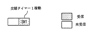
図11A〜図11Cは、最悪の状況に対して交錯タイマー周期T1の最大値がどのように計算されるかを示した図である。図11Aは、送信シーケンスナンバーがSN1のデータブロックが受信されたが、直前のデータブロックは受信されないことを示した図である。以前に説明したように、交錯タイマーはデータブロックSN1のために再稼動される。
【0181】
図11Bは、交錯タイマーが動作する間、データブロックSN4を除外した連続された送信シーケンスナンバーを有する各データブロックの受信を示した図である。この時、データブロックSN4は決して受信されないと仮定されるが、例えば、UTRANがデータブロックの再伝送を要求する再使用者装置から伝送された不正応答(NACK)信号を応答信号に誤って解析したり、またはUTRANが失敗でデータブロックを削除するため、データブロックは使用者装置に再伝送されない。
【0182】
交錯タイマーが終了される時、データブロックSN1は上位階層に伝達されるが、遺失データブロックSN4のためにデータブロックSN2を含むデータブロックSN2までの受信された他のデータブロックは伝達されない。その代りに、前記各ブロックはバッファーに維持され、交錯タイマーはHSNのデータブロック、即ち、SN2のために再稼動される(または、第2交錯タイマー2が稼動される)。理論的には、送信シーケンスナンバーSN2の最高値はSN1+T1/(2ms)である。
【0183】
図11Cは、前記交錯タイマーの第2周期の間全ての連続データブロックは正確に受信されたことを示した図である。前記第2タイマー周期が終了されると、再整理バッファーに格納された最後のデータブロックはデータブロックSN3である。理論的に、送信シーケンスナンバーSN3の最高値はSN2+T1/(2ms)=SN1+T1である。従って、第2交錯タイマー周期の間受信機によって受信される前記データブロックの範囲は[SN4、SN3]=[SN+1、SN+T1]である。
【0184】
前記したように、データブロックに割り当てられる送信シーケンスナンバーの範囲は0から63までである。従って、送信シーケンスナンバーSN3は送信シーケンスナンバーSN4+64より大きいか同様である時、前記使用者装置の受信機は、後で受信された各データブロックが図面で示されたデータブロックSN2の前後で受信されたかを決定することができない。このようなラップアラウンド条件は、限定された数の送信シーケンスナンバーのみがデータブロックに割り当てられるため発生される。
【0185】
ラップアラウンド条件が発生しないようにするために、本発明の発明者等は、送信シーケンスナンバーSN3はSN4+64であるか、またはそれ以下であるべきと決定した。SN3の最大値は、SN3=SN4+64−1=SN1+64で表現される。それは、SN3=SN1+T1、即ち、T1の最大値が理論的に64msでなければならないためである。従って、もし前記交錯タイマー周期T1が64msであるか、それ以下の値に設定されると、前記TSNラップアラウンド条件は発生しないはずである。本発明のRRCは、再整理バッファーの動作が管理される方法に対するこれら基準によって交錯タイマーを調節する。
【0186】
一般的に、各データブロックに割り当てられる各送信シーケンスナンバーの範囲がN個で、前記TTIが2msであると、前記交錯タイマー周期の最大値はN×TTI/2になるべきである。前記交錯タイマーの周期が64msより大きいと、最悪の場合、再整理バッファーに以前に格納されたデータブロックの伝送シーケンスナンバーと同じか、重複された番号を有する新しいデータが交錯タイマーが終了される前に受信される。然し、この場合、二つのデータブロック中一つ、好ましくは、前記重複された番号を有するデータブロックが廃棄される。従って、各TSN番号の範囲が64であり、TTIが2msである時、送信シーケンスナンバーのラップアラウンドを防止するために、交錯タイマーの最大周期は64msより大きくなってはならない。
【0187】
実際の動作時、UTRANが2×T1の時間周期で端末が受信しなかったデータブロックを伝送(または再伝送)しないことが好ましい。これは、受信機がラップアラウンド条件を違反せず、データブロックを待つこともできる最大受信待機時間が2×T1であるためである。この時間以後に再伝送された各データブロックはいくら正確に受信されるとしても、使用者装置により廃棄される。従って、好ましくは、UTRAN内でそれぞれのHARQのために廃棄タイマーが供給され、該廃棄タイマーの周期は使用者装置の受信機内で交錯タイマー周期の2倍のみに設定される。
【0188】
図12A及び図12Bは、交錯状態を回避する方法で、どうように本発明の方法が再整理バッファーで各データブロックの格納を管理する交錯タイマーを動作させるかを示した一例である。
【0189】
初期に、例えば、移動端末機受信機にあるMAC階層は、送信シーケンスナンバー13、14を有する各データブロックを順次的に受信する。各先行データブロックが直に上位層に伝達されたため、データブロック13、14は再整理バッファーに格納されず上位階層に伝達される。然し、送信シーケンスナンバー18を有するデータブロックが受信される時、各先行データブロック15、16、17は受信されないと検出されるため、データブロック18は再整理バッファーに格納されて交錯タイマーが動作される。交錯タイマーが動作される時、ただ、データブロック18のみが再整理バッファー内に格納され、このような状況は、図12Aに示されている。
【0190】
交錯タイマーの周期の間、MAC階層はどのデータブロックが受信されたかを検査する。図12Bに示したように、データブロック16が連続されたデータブロック18、19、20、22、23、25に従って、この時間の間受信される。データブロック21、24は受信されないと検出される。
【0191】
交錯タイマー周期が終了される時、本発明では、データブロック16がデータブロック18と共に伝達される。また、データブロック19、20が送信シーケンスナンバー順に(例えば、データブロック18、19、20間に遺失データブロックが存在しないため)順次的にデータブロック18に従っているため、データブロック19、20は、追加遅延なしに上位階層に伝達される。伝達された全てのデータブロックは、例えば、以後受信される各データブロックの格納空間を確保するため、再整理バッファーから削除される。また、使用者装置のMAC階層は、データブロック15、17がタイマー周期の終了以前に受信されないと、UTRANにデータブロック15、17を再伝送しないように指示するメッセージを送信することができる。
【0192】
データブロック22、23、25は、データブロック21が受信されなかったため、交錯タイマーが終了される時伝達されない。その代わりに、交錯タイマーが終了された時、再整理バッファーにHSNのデータブロックが検出される。
【0193】
この場合、HSNのデータブロック25は、再整理バッファーで最も大きい伝送番号を有するものに対応する。しかし常にそうではない。各データブロックに割り当てられる送信シーケンスナンバーの範囲が限定されているため、連続されたデータブロック63、0、1、2が再整理バッファー内に格納される場合に該当され、この場合、HSNのデータブロックは、最も大きい送信シーケンスナンバーを有するデータブロックに対応しないはずである。このような場合が図13に図式的に示されている。従って、本発明は、必ず最も大きい送信シーケンスナンバーを有するデータブロックでなく、バッファーにあるHSNの各データブロックと一致させて交錯タイマーを再稼動させることが好ましい。
【0194】
バッファーにあるHSNのデータブロックが検出された後、交錯タイマーは再稼動される。この時間の間、付加的なデータブロックが受信されて、一部はデータブロック21、24が含まれる。データブロック21が交錯タイマー周期の間受信されると、データブロック21、22、23は順次的に上位階層に伝達される。次いで、もしデータブロック24が交錯タイマー周期の間受信されると、データブロック24、25及び以後の連続されたデータブロックが上位階層に伝達され、前記交錯タイマーは動作を停止する。然し、もしデータブロック21、24が交錯タイマー周期の間受信されないと、データブロック22、23、25及び連続されたデータブロックは、ただ交錯タイマーが終了された後上位階層に伝達される。該伝達された各ブロックは、バッファーから廃棄されてその過程は継続される。
【0195】
本発明の実施形態に関連して、再整理バッファーはただ一つの交錯タイマーによって調節されることが好ましい。
【0196】
交錯状況を防止するための本発明の方法の他の実施形態は、最初の実施形態のようなMAC階層構造を含む使用者装置で遂行される。然し、前記再整理バッファーが制御される方法は異なる。
【0197】
この実施形態と関連して、次の定義が適用される。”次の予想TSN(Next_expected_TSN)”という用語は、順次受信された最後のMACプロトコルデータユニット(PDU)の送信シーケンスナンバーに従う送信シーケンスナンバーに対応する。それは、’次の予想TSN’と同様な送信シーケンスナンバーと共に、MAC−hs PDUが受信され次第、直に更新され、前記次の予想TSNの初期値は0である。
【0198】
”送信機ウインドー”は、どのMAC−hs PDUをUTRAN送信機が受信機で混同を惹起させないで再伝送することができるかを表す用語である。本実施形態で、前記送信機ウインドーの最大サイズは32で、初期送信機ウインドーは[0....31]であり、各上位階層による送信機ウインドーの構成はFFSである。
【0199】
”受信機ウインドー”とは、下記の手続によって、受信機ウインドーを増加させないで、受信機でどのMAC−hs PDUを受信し得るかを表す用語である。受信機ウインドーの最大サイズは32で、初期受信機ウインドーは[0....31]で、各上位階層による受信機ウインドーの構成はFFSである。
【0200】
本実施形態で、交錯タイマーは、MAC階層で再整理バッファーを調節して、特に、使用者端末機のMAC−hs副階層を制御する。前記交錯タイマー周期は、以前に言及されたラップアラウンド条件を回避するために各上位階層により調節される。
【0201】
初期に、交錯タイマーT1は非活性化される。前記交錯タイマーは、TSN=SNと共に、一つのMAC−hs PDUが正確に使用者端末機により受信される時稼動されるが、’次の予想TSN’と同様なTSNを有するMAC−hs PDUが遺失されるため、該当の分解機能に伝達されない。前記交錯タイマーが既に活性化された場合、如何なる追加的な交錯タイマーやタイマー周期が再稼動されない。即ち、ただ一つのタイマーT1のみが与えられた時間の間活性化される。
【0202】
前記交錯タイマーT1は、もしタイマーを稼動させたMAC−hs PDUが交錯タイマーT1が終了される前に分解機能に伝達されるなら、動作を停止するはずである。
【0203】
前記交錯タイマーT1が終了される時、SN−1を含む、そしてSN−1まで正確に受信された全てのMAC−hs PDUは前記分解機能に伝達され、伝達された各MAC−hs PDUは再整理バッファーから除去される。また、例えば、SNのMAC−hs PDUに従う最初に漏れたMAC−hs PDUまで正確に受信された全てのMAC−hs PDUが分解機能に伝達される。
【0204】
タイマーT1が停止したり終了される時にも、上位階層に伝達されない多少の受信されたMAC−hs PDUが存在する場合、前記交錯タイマーT1は伝送されない各MAC−hs PDU中、最も大きい送信シーケンスナンバーを有するMAC−hs PDUのために再稼動される。
【0205】
前記送信機は次のように動作する。送信機(例えば、UTRAN)がTSN=SNを有するMAC−hs PDUを伝送した後、送信機ウインドーでTSN#SNを有するMAC−hs PDUはシーケンスナンバーの混同を避けるために再伝送されてはならない。一回以上伝送された後、送信機により中断されたMAC−hs PDUは中断された後再伝送されてはならない。
【0206】
使用者端末は次のように動作される。まず、全てのHARQプロセスで各ソフトバッファーが空いていると、例えば、前記バッファー内に以後の受信されるデータとソフト結合するデータが存在しないと、正確に受信された全てのMAC−hs PDUは分解機能に伝達され、これらMAC−hs PDUは次の手続で受信されたものとみなされる。
【0207】
交錯タイマーの終了時に廃棄されたMAC−hs PDUは次の手続で受信されることと見なされる。TSN=SNを有するMAC−hs PDUが受信される時、次の工程が遂行される。もしSNが受信機ウインドー内にあり、MAC−hs PDUが以前に受信されてなかったなら、MAC−hs PDUは、送信シーケンスナンバーが表れる再整理バッファーの位置に置かれる。もしSNが前記受信機ウインドー内にあり、前記MAC−hs PDUが以前に受信されたなら、前記MAC−hs PDUは廃棄される。
【0208】
もしSNが受信機ウインドーの外側にあるなら、受信されたMAC−hs PDUは再整理バッファー内でSNにより指称された位置、即ち、受信された最も大きいTSNに上ウに位置されるはずである。前記受信機ウインドーは、SNが受信機ウインドーの上位エッジ(edge)を形成するように増加される。受信機ウインドーでTSN#SNを有するMAC−hs PDUは、分解エンティティーへの伝達のために再整理バッファーから除去される。
【0209】
次の予想TSNから最初に未受信されたMAC−hs PDUまで、連続的な送信シーケンスナンバーTSNを有する全ての受信MAC−hs PDUは分解エンティティーまで伝達され、前記最初に未受信されたMAC−hs PDUのTSNは、次の予想TSNになる。
【0210】
また、本発明は、今まで言及された本発明の方法の実施形態に含まれた各工程を行う各コードセクションを有するコンピュータプログラムである。該コンピュータプログラムは、使用者端末機内で支持される如何なるコンピュータ言語によっても使用され、前記端末内で、または端末に接続される永久的か除去可能なコンピュータ−判読可能(computer−readable)媒体に格納される。永久的なコンピュータ−判読可能媒体はROMとRAMを含むが、これに限定されない。除去可能な各媒体は、EPROM、EEPROM、数多いメモリースティックまたはカード中一つまたは他の形態の除去可能な格納媒体を含んでいるが、これに限定されない。各フラッシュメモリーは、本発明の前記コンピュータプログラムを格納するために使用される。
【0211】
本発明は、UTRA高速ダウンリンクパケット接続(HSDPA)の全体技術を担当する3GPP技術規格TS25.308及びMACプロトコル規格を担当する3GPP技術規格TS25.321で採択されてきた。これら文書は、参考としてここで具体化される。
【0212】
本発明の他の修正と変形は、該当の知識を有する者には明らかなものである。従って、本発明の確実な例示が具体的にここに記述される限り、数多くの変形が本発明の該当の範囲を脱しない範囲内で可能である。
【0213】
先に言及した実施形態とその利点は単純な例に過ぎなく、本発明に局限されない。本発明の技術は多様に適用される。本発明に対する記載は、ただ説明のためのものであり、請求項の範囲を限定しない。また、通常の知識を有する者なら本発明に対して修正、変化、変形が可能である。
【0214】
【発明の効果】
以上説明したように、本発明は、バッファーに存在するデータブロックの量を制限することで交錯状況を有効に防止し、よって、伝送効率と受信されたデータの信頼性を向上し得るという効果がある。
【図面の簡単な説明】
【図1】3GPP通信システムにおける3GPP UTRANの構造を示した図である。
【図2】3GPP RAN規格に基づいて動作する端末とUTRAN間の無線接続インターフェースプロトコルの構造を示した図である。
【図3】HSDPAシステムを支援するための無線インターフェースプロトコル構造を示した図である。
【図4】HSDPAシステムで使用され、MAC−d下位層、MAC−c/sh副階層及びMAC−hs副階層を含むMAC階層の構造を示した図である。
【図5】HSDPAシステムにおける使用者端末のMAC階層の構造を示した図である。
【図6】HSDPAシステムでデータブロックを送受信するためのプロセスを示した図である。
【図7】本発明の実施形態に係る使用者端末機を示した図である。
【図8A】本発明の実施形態に係る再整理バッファーで交錯状況を回避するための方法に含まれた工程を示した図である。
【図8B】本発明の実施形態に係る再整理バッファーで交錯状況を回避するための方法に含まれた工程を示した図である。
【図8C】本発明の実施形態に係る再整理バッファーで交錯状況を回避するための方法に含まれた工程を示した図である。
【図9】本発明に係る最初の制御手続を示したタイミング図である。
【図10A】HSDPAシステムで交錯状況を回避するための本発明の方法に係る他の実施形態を示した図である。
【図10B】HSDPAシステムで交錯状況を回避するための本発明の方法に係る他の実施形態を示した図である。
【図11A】最悪の場合に備えて、交錯タイマー周期T1の最大値がどのように計算されるかを示した図である。
【図11B】最悪の場合に備えて、交錯タイマー周期T1の最大値がどのように計算されるかを示した図である。
【図11C】最悪の場合に備えて、交錯タイマー周期T1の最大値がどのように計算されるかを示した図である。
【図12】図12Aは、どのように本発明の方法が、再整理バッファーでデータブロックの格納を管理する交錯タイマーを運用して交錯状況を回避するかに対する一例を示した図である。図12Bは、どのように本発明の方法が、再整理バッファーでデータブロックの格納を管理する交錯タイマーを運用して交錯状況を回避するかに対する一例を示した図である。
【図13】どのように本発明の方法が状況に適用され、再整理バッファーに格納されたデータブロックのシーケンスナンバーが再使用されるためにどこから開始されるかに対する一例を示した図である。
【符号の説明】
320 再整理キュー分配部
330 再整理バッファー
340 交錯タイマー
360 MAC制御器[0001]
BACKGROUND OF THE INVENTION
The present invention relates to wireless communication, and more particularly to a system and method for improving the transmission efficiency of packet data received by a receiver in a mobile communication wireless system.
[0002]
[Prior art]
UMTS (Universal Mobile Terrestrial System) is a third household mobile communication system that evolved from the European standard GSM (Global System for Mobile Communications) system. The aim is to provide improved mobile communication services based on technology. ETSI in Europe, ARIB / TTC in Japan, T1 in the United States, and TTA in Korea in December 1998 for UMTS standardization work, Third Generation Partnership Project (hereinafter abbreviated as 3GPP) A detailed standard specification (Specification) of UMTS is being created so far.
[0003]
In 3GPP, for rapid and efficient technology development of UMTS, considering the independence of each network component and their operation, UMTS standardization work is divided into five technical specification groups (hereinafter referred to as TSG). Are abbreviated as). Each TSG is responsible for the development, approval, and management of standards within the associated area, among which the Radio Access Network (hereinafter abbreviated as RAN) group (TSG-RAN) UMTS wireless network (Universal Mobile Telecommunications Wireless Radio Access Network; hereinafter abbreviated as UTRAN) functions, requirements, and high-speed interface to support WCDMA connection technology in UMTS.
[0004]
The TSG-RAN group is composed of a general meeting (Plenary) group and four operating groups (Working Group). The first operating group (WG1: Working Group 1) has developed a standard for the physical layer (first layer), and the second operating group (WG2: Working Group 2) has a data link layer (second layer) and a network layer (third layer). ). The third management group defines the standards for the interface between the UTRAN base station, radio network controller (hereinafter abbreviated as RNC), and core network (Core Network), and the fourth management group uses the radio network controller (Radio Network Controller; hereinafter referred to as RNC). Discuss requirements for link performance and requirements for radio resource management.
[0005]
FIG. 1 is a diagram illustrating the structure of 3GPP UTRAN to which the present invention and the present invention are applied.
[0006]
As shown in the figure, the UTRAN 110 includes one or more radio network sub-systems (hereinafter abbreviated as RNS) 120 and 130, and each
[0007]
The base stations (Node B) (122, 123) (130, 133) are managed by the
[0008]
The
[0009]
FIG. 2 is a diagram illustrating the structure of a radio connection interface protocol between a terminal and a UTRAN operating based on the 3GPP RAN standard. The wireless interface protocol is composed of a physical layer (PHY), a data link layer, and a network layer in a horizontal direction, and vertically transmits a control plane (Control Plane) for transmitting control information and data information. It is divided into a user plane. The user plane is an area where user traffic information such as voice and IP packets is transmitted, and the control plane is an area where control information such as network interface and call maintenance and management is transmitted. .
[0010]
In FIG. 2, each protocol layer is divided into a first layer (L1), a second layer (based on the lower three layers of the Open System Interconnection (OSI) standard model widely known in communication systems. L2) and the third layer (L3).
[0011]
The first layer (L1) is operated as a physical layer (PHY) for a wireless interface, and is connected to a higher layer medium control (Medium Access Control) through one or more transport channels. Connected to the hierarchy. The physical layer transmits the data transmitted to the physical layer (PHY) through the transport channel to the receiver using various coding and modulation methods suitable for the wireless environment. Depending on whether a transmission channel existing between the physical layer (PHY) and the MAC layer is used exclusively by a terminal or shared by various terminals, a dedicated transmission channel (Dedicated Transport Channel) and a shared transmission channel ( Common Transport Channel).
[0012]
The second layer (L2) operates as a data link layer (Data Link Layer), and allows various terminals to share the radio resources of the WCDMA network. The second layer (L2) includes a MAC layer, a radio link control (hereinafter referred to as RLC) layer, a packet data convergence protocol (hereinafter referred to as PDCP) layer, and a broadcasting / It is divided into a multicast control (Broadcast / Multicast Control; hereinafter abbreviated as BMC) hierarchy.
[0013]
The MAC layer transmits data through an appropriate mapping relationship between a logical channel and a transmission channel. Each logical channel is a channel that connects an upper layer to a MAC layer, and various logical channels are provided according to the type of information to be transmitted. In general, a control channel is used when information on the control plane is transmitted, and a traffic channel is used when information on the user plane is transmitted. The MAC layer is divided into two sub-layers according to the function to be performed again, that is, a MAC-d sub-layer that is located in the SRNC and manages a dedicated transmission channel, and a MAC-c / that is located in the CRNC and manages a shared transmission channel. It is divided into sh sub-hierarchies.
[0014]
The RLC layer forms an RLC protocol data unit (PDU) suitable for transmission by dividing and concatenating RLC service data units (Service Data Units: SDUs) received from an upper layer. In addition, an automatic repeat request (ARQ) function responsible for retransmission of a lost RLC PDU during transmission can be performed. The RLC layer operates in three modes: a transparent mode, a no-response mode, and an acknowledged mode. The selected mode depends on a method for processing RLC SDUs received from an upper layer, and the RLC layer includes an RLC buffer for storing RLC SDUs or RLC PDUs received from an upper layer. .
[0015]
The PDCP layer is an upper layer of the RLC layer, and adapts each data transmitted through a network protocol such as IPv4 or IPv6 to be transmitted from the RLC layer. At this time, for efficient transmission of IP packets, header compression (Header Compression) technique for compressing and transmitting packet header information is used.
[0016]
The BMC layer enables a message transmitted from a CBS (Cell Broadcast Center) to be transmitted through a wireless interface. The main function of the BMC is to schedule and transmit a cell broadcast message transmitted to a terminal, thereby transmitting data through an RLC layer that generally operates in a no-response mode.
[0017]
The PDCP layer and the BMC layer are connected to the SGSN in order to use a packet switching method, and are located only on the user plane in order to transmit only user data. Unlike the PDCP layer and the BMC layer, the RLC layer may belong to a user plane or a control plane depending on a layer connected to an upper layer. When the RLC layer belongs to the control plane, the data is received from a radio resource control (hereinafter referred to as RRC) layer, and otherwise, the RLC layer belongs to the user plane. In general, a user data transmission service provided from the user plane to the upper layer by the second layer (L2) is defined as a radio bearer (RB), and the control layer is defined by the second layer (L2). The control information transmission service provided to the upper layer is defined as a signaling radio bearer (SRB). Also, as shown in FIG. 2, in the case of the RLC layer and the PDCP layer, there are several entities in one layer. This is because one terminal has multiple radio carriers (RB), and usually one or two RLC entities and only one PDCP entity is used for one radio carrier (RB). Because. Each entity in the RLC layer and the PDCP layer can perform an independent function in each layer.
[0018]
The RRC layer located at the bottom of the third layer (L3) is defined only in the control plane, and controls the transmission channel and the physical channel in association with the setting, reconfiguration and release of each radio carrier (RB). At this time, setting the radio carrier means defining the protocol layer and channel characteristics necessary to provide a specific service, and setting the specific parameters and operation methods of each. . The RRC layer can also transmit each control message transmitted in an upper layer through the RRC message.
[0019]
The WCDMA system targets a transmission rate of 2 Mbps in indoor and pico-cell cell environments and a transmission rate of 384 kbps in a general wireless environment. However, as the wireless Internet becomes universal and the number of subscribers increases, it is expected that more various services will be provided and that a high transmission rate will be required to support such services. Therefore, in the current 3GPP, research for developing a WCDMA network to provide a high transmission rate is underway, and among them, as a typical system, a high speed downlink packet access (HSDPA) is provided. ) The system is known.
[0020]
The HSDPA system is expected to support speeds up to 10 Mbps on the downlink, based on WCDMA, and provide shorter delay times and improved capacity. The techniques applied in the HSDPA system to provide improved transmission rate and capacity include link adaptation (hereinafter abbreviated as LA), hybrid automatic repeat request (hereinafter abbreviated as HARQ). Fast cell selection (hereinafter abbreviated as FCS), multiple-input multiple-output (hereinafter abbreviated as MIMO) antenna techniques, and the like can be devised.
[0021]
The link adaptation technique (LA) uses a modulation and coding scheme (hereinafter abbreviated as MCS) according to a channel state, and when the channel state is good, a high level such as 16QAM and 64QAM ( A high degree modulation method is used, and when the channel condition is not good, a low degree modulation method such as QPSK is used.
[0022]
In general, the low-level modulation method has a smaller transmission amount than the high-level modulation method, but exhibits an excellent transmission success rate when the channel environment is not good. Therefore, the influence of fading or interference is exerted. Larger is advantageous. On the other hand, the advanced modulation method has much better frequency utilization efficiency than the low-level modulation method, and can provide a transmission rate of 10 Mbps using the 5 MHz bandwidth of WCDMA. However, it is very sensitive to the effects of noise and interference. Therefore, when the terminal is located near the base station, the transmission efficiency can be increased by using 16QAM or 64QAM. When the terminal is located at a cell boundary or when fading influence is large, QPSK is used. A low-level modulation technique such as
[0023]
The HARQ method is a retransmission method having a concept different from the retransmission method used in the RLC layer. The HARQ method is used in conjunction with the physical layer, and combines the retransmitted data with the previous received data to ensure a higher decoding success rate. That is, a packet that has failed to be transmitted is not discarded, but stored, and the stored packet is combined with a retransmission packet and decoded in a process before decoding. Therefore, when the HARQ method is used with the LA technique, the transmission efficiency of the packet can be greatly increased.
[0024]
The FCS method is a concept similar to the existing soft handover. The terminal can receive data from several cells, but considers the channel state of each cell and receives data from the cell with the best channel state. The existing soft handover is a method of receiving data transmission from several cells and using diversity to increase the transmission success rate. However, the FCS method is specified to reduce interference between cells. Data is transmitted from only one cell.
[0025]
The MIMO antenna technique is a method of improving the data transmission rate by using several independent channels in a channel environment where a lot of scattering occurs. Usually, this system is composed of several transmitting antennas and several receiving antennas, and reduces the relevance between radio waves received for each antenna, thereby obtaining a diversity gain.
[0026]
On the other hand, the HSDPA system tries to introduce a new technology based on an existing WCDMA network while maintaining the WCDMA network as it is. However, some modifications are inevitable to introduce new technologies. A typical example is the improvement of the existing base station (Node B) function. That is, in WCDMA networks, most of the control functions are located in the RNC, but new technologies for the HSDPA system are mostly used for base stations (Node B) to adapt to the channel conditions faster and reduce the delay time to the RNC. ) To manage. However, the extended function of the base station (Node B) is not a function performed on behalf of the RNC, but from the standpoint of the RNC, it is considered to be responsible for an auxiliary function to which a function for high-speed data transmission is added. Can do.
[0027]
Therefore, unlike the existing WCDMA system, the base station (Node B) is modified to perform a part of the MAC function, and a layer that performs this is called a MAC-hs sub-layer.
[0028]
The MAC-hs sub-layer is positioned above the physical layer and can perform packet scheduling and HARQ and LA functions. The MAC-hs sublayer uses a new transmission channel called HS-DSCH (High Speed-Downlink Shared Channel) used for HSDPA data transmission. This HS-DSCH channel is used when data is exchanged between the MAC-hs sub-layer and the physical layer.
[0029]
FIG. 3 is a diagram illustrating a radio interface protocol structure for supporting the HSDPA system. As illustrated, the MAC layer is roughly divided into three sub-layers, a MAC-d sub-layer, a MAC-c / sh sub-layer, and a MAC-hs sub-layer. The MAC-hs sub-layer is located on the physical layer (PHY) of the base station (Node B), and the MAC-c / sh and MAC-d sub-layers are located in the CRNC and SRNC, respectively, as in the conventional system. To do. In addition, for transmission of HSDPA data, a new transmission protocol called HS-DSCH FP (Frame Protocol) is used between the RNC and the base station (Node B) or between each RNC.
[0030]
At this time, the MAC-c / sh sub-layer, the MAC-d sub-layer, the RLC layer, and the like positioned above the MAC-hs sub-layer perform the same functions as the current system. Therefore, it is sufficient for the RNC to support HSDPA to add only some software in the current system.
[0031]
FIG. 4 is a diagram illustrating the structure of the MAC layer used in the HSDPA system.
[0032]
As illustrated, the MAC layer is divided into a MAC-d sublayer 161, a MAC-c / sh
[0033]
With reference to FIG. 4, a description will be given of how the data from the RLC layer is transmitted to the HS-DSCH through the MAC layer.
[0034]
RLC PDUs transmitted from the RLC layer through the dedicated logical channel DTCH (Dedicated Traffic Channel) or DCCH (Dedicated Control Channel) are routed through the channel switching function in the MAC-d layer. When transmitted to a dedicated transmission channel (DCH: Dedicated Channel), a related header is attached in the MAC-d sub-layer 161 and is transmitted to the physical layer through the DCH (Dedicated Channel), and the HS-DSCH channel of the HSDPA system is transmitted. When used, RLC PDUs are sent to the MAC-c / sh sublayer by the channel switching function. When a plurality of logical channels use a single transmission channel, the RLC PDU passes through a transmission channel multiplexing block. During this process, identification information (control / traffic field) of the logical channel to which each RLC PDU belongs is added, each logical channel has a priority, and the logical channel data has the same priority. Have.
[0035]
When the MAC-d PDU is transmitted, the MAC-d sublayer 161 transmits the priority order of the MAC-d PDU. The MAC-c / sh
[0036]
Then, a data block size suitable for the channel state is selected by a scheduling function. Thus, a data block is formed by combining one or more MAC-hs SDUs.
[0037]
A priority identifier (priority class identifier) and a transmission sequence number (Transmission sequence number) are added to each data block, and the corresponding data block is transmitted to the HARQ block. There are up to 8 HARQ processes in the HARQ block. Data blocks received from the scheduling block are communicated to the appropriate HARQ process. Each HARQ process operates in a stop and standby (SAW) ARQ. In this way, the next data block is not transmitted until the current data block has been successfully transmitted. As described above, since only one data block is transmitted in one TTI, only one HARQ process is activated in one TTI.
[0038]
Other HARQ processes wait until they are in order. Each HARQ process has a HARQ process identifier. The corresponding HARQ process identifier is known to the terminal in advance through a downlink control signal, and a specific data block undergoes the same HARQ process at the transmitter (UTRAN) and the receiver (terminal). Also, the HARQ process that has transmitted the data block stores the data block in order to define future retransmissions. When a NACK (NonACKknowledge) is received from the terminal, the data block is retransmitted. When the ACK is received from the terminal, the HARQ process deletes the corresponding data block and prepares to transmit a new data block. When the data block is transmitted, a transport format and resource combination (TFRC) block selects an appropriate TFC for the HS-DSCH.
[0039]
FIG. 5 is a diagram illustrating the structure of the MAC layer used in the HSDPA system. The MAC layer is divided into a MAC-
[0040]
Hereinafter, a process in which the MAC layer receives data from the physical layer and transmits the data to the RLC layer will be described with reference to FIG. The data block transferred to the MAC-hs sublayer 171 through the HS-DSCH is first stored in any one of the various HARQ processes in the HARQ block. At this time, in which process the data block is stored can be known from the HARQ process identifier included in the downlink control signal.
[0041]
The HARQ process in which the data block is stored, if there is an error in the data block, transmits NACK information to the UTRAN to request retransmission of the data block. If there is no error, the data block is reordered (Reordering) buffer. ACK information is transmitted to UTRAN. The rearrangement buffer has the same priority as the UTRAN transmission buffer. The HARQ process communicates the data block to the reordering buffer through the priority identifier included in the data block. A major characteristic of the rearrangement buffer is that it supports the sequential transmission of data.
[0042]
Each data block is sequentially transmitted to an upper layer based on a transmission sequence number (TSN). More specifically, when one or more previous data blocks are lost, when a data block is received, the data block is stored in a reorder buffer and is not transmitted to the upper layer. Then, the data block is transmitted to the upper layer only when the previous data block is received and transmitted to the upper layer. Since several HARQ processes are operated, the reordering buffer can receive data blocks non-sequentially. Therefore, a sequential transmission function is used for the rearrangement buffer so that each data block is sequentially transmitted to the upper layer.
[0043]
The difference between the terminal rearrangement buffer and the UTRAN transmission buffer is that the rearrangement buffer stores data in units of data blocks composed of one or more MAC-hs SDUs, and the transmission buffer is MAC-has. Data is stored in units of SDU (= MAC-d PDU). Since the MAC-
[0044]
FIG. 6 is a diagram illustrating a process for transmitting and receiving data blocks in the HSDPA system. Each MAC-d PDU is actually stored in the transmission buffer 160, but for convenience, it is shown as a data block (= one or more MAC-d PDUs). In addition, although the size of each data block may vary, it is similarly shown in the drawing. It was also assumed that there were 8 HARQ processes (181-188).
[0045]
The process indicates that each data block from TSN = 13 to TSN = 22 in the transmission buffer is transmitted to the receiver. From a data block with a low TSN is conveyed to an empty HARQ process. For example, a data block with TSN = 13 is transmitted to
[0046]
When the HARQ process receives an arbitrary data block, the HARQ process transmits the data block from a specific TTI to the receiver and stores the corresponding data block for later retransmission. Since only one data block is transmitted in a specific TTI, only one HARQ process is activated in one TTI. The HARQ process that transmitted the data block informs the receiver of its data block number through a downlink control signal transmitted on a channel different from that of the data block.
[0047]
The reason for matching the HARQ processes of the transmitter and the receiver is that a stop-and-wait (SAW) ARQ method is used by each HARQ process pair. That is, the
[0048]
A rearrangement buffer exists for each priority level. The HARQ process checks the priority included in the header information of the data block, and then transmits the data block to the reordering buffer according to the priority. Then, when all previous data blocks are transferred to the upper layer, the data block is transferred to the upper layer. However, if one or more previous data blocks are not transmitted to the upper layer, the data blocks are stored in the
[0049]
FIG. 6 shows that when a data block of TSN = 14 is received, the data block of TSN = 13 is not received, and the data block of TSN = 14 is stored in the rearrangement buffer until the data block of TSN = 13 is received. Indicates that it will be stored. When the data block of TSN = 13 is received, all of the two data blocks are transmitted to the upper layer in the order of TSN = 13 and TSN = 14. When each data block is transmitted to the upper layer, each data block is divided and transmitted in units of MAC-d PDUs.
[0050]
[Problems to be solved by the invention]
However, the reordering buffer has at least one drawback. Since the reordering buffer supports the sequential transmission of each data block, if a specific data block is not received, each data block having a TSN is not transmitted to the upper layer later but stored in the reordering buffer. If a specific data block is not received for a long time or permanently, each data block in the reordering buffer is not transmitted to the upper layer. Moreover, after a short period of time, the buffer is fully filled so that no additional data blocks can be received, thus leading to a stall situation.
[0051]
If a crossing situation occurs and a specific data block is not received for a long time or permanently, the transmission efficiency of the HSDPA system is degraded. In more detail, if a plurality of data blocks are stored in the MAC-hs buffer for a long time due to one missing data block, the data transmission efficiency of the entire system is lowered. This damages the advantages of many HSDPA systems such as providing high speed data communication.
[0052]
The data block is not permanently received for one of the following two reasons.
[0053]
1) When UTRAN erroneously determines the NACK signal sent by the terminal as an ACK signal
2) The data block is retransmitted the maximum number of times allowed by the system, or the transmission is not successfully performed for a predetermined time, and the UTRAN HARQ process discards the data block
In the case of 1), UTRAN erroneously decodes the status information sent by the terminal. In the case of 2), since the specific data block was not successfully transmitted for a long time, the UTRAN specified the specified information. In this case, the data block is discarded. However, UTRAN does not inform the terminal of the discard fact. In this case, since the data block is not transmitted permanently, the subsequent data block remains in a state of being stored in the rearrangement buffer without being transmitted to the upper layer. Therefore, there is an inconvenience that the protocol is in a mixed state.
[0054]
Therefore, in a mobile communication system, there is a need for a method for correcting the crossing condition of the rearrangement buffers of the communication receiver and improving the voice and data transmission efficiency.
[0055]
The present invention has been made in view of such a conventional problem, and an object of the present invention is to provide a system and a method for improving the quality of communication in a mobile communication system.
[0056]
It is another object of the present invention to prevent the crossing situation at the user terminal to achieve the above-mentioned object and improve the transmission efficiency of the system.
[0057]
It is another object of the present invention to achieve the aforementioned object by using a crossing timer that limits the amount of each time data block stored in the reordering buffer of the receiver.
[0058]
It is another object of the present invention to set the cycle of the crossing timer by a value that prevents the wrap-around condition from occurring for the transmission sequence number assigned to the data block stored in the buffer.
[0059]
It is another object of the present invention to provide a system and method that can prevent the reorganization buffer from intermingling and at the same time prevent the data blocks that are correctly received and stored in the buffer from being lost.
[0060]
[Means for Solving the Problems]
The packet data processing method in the receiver of the communication system of the present invention includes a step of receiving a data block having a sequence number, a step of storing the data block in a rearrangement buffer, and a data block of a preceding sequence number being lost, When the timer is inactive, a step of operating a timer for the rearrangement buffer is sequentially performed.
[0061]
The packet data processing method in the receiver of the communication system of the present invention may be characterized in that the timer is the only timer provided for controlling the rearrangement buffer.
[0062]
The packet data processing method in the receiver of the communication system according to the present invention includes the step of receiving at least one additional data block after the timer is activated, and the lowest sequence among the lost data blocks in which the data block is expected. If it is not a number data block, the step of storing the at least one additional data block in a rearrangement buffer may be further performed.
[0063]
In the packet data processing method in the receiver of the communication system according to the present invention, the timer is terminated when the additional data block is a data block having a sequence number preceding the sequence number of the data block stored when the timer is operated. In this case, a step of removing the additional data block from the rearrangement buffer may be further performed.
[0064]
The packet data processing method in the receiver of the communication system according to the present invention may further include a step of transmitting the additional data block to an upper layer.
[0065]
In the packet data processing method in the receiver of the communication system according to the present invention, the additional data block is a data block having a sequence number that precedes the sequence number of the data block stored when the timer is operated. When all the data blocks are received, a step of removing the additional data blocks from the reordering buffer may be further performed when the timer is expired.
[0066]
The packet data processing method in the receiver of the communication system according to the present invention may further include a step of transmitting the additional data block to an upper layer.
[0067]
A packet data processing method in a receiver of a communication system according to the present invention includes a step of operating a timer for a rearrangement buffer, a step of receiving a data block having a sequence number, and storing the data block in the rearrangement buffer. And sequentially removing the data block from the rearrangement buffer when the sequence number of the data block is received when the timer is activated and precedes the sequence number of the data block stored in the rearrangement buffer. It is characterized by that.
[0068]
In the packet data processing method in the receiver of the communication system of the present invention, when the sequence number of the data block is received when the timer is operating and precedes the sequence number of the data block stored in the rearrangement buffer, A step of transmitting the data block received in the receiving step at the end may be further performed.
[0069]
The packet data processing method in the receiver of the communication system of the present invention further includes a step of transmitting the data block received when the timer is activated and stored in the rearrangement buffer to the upper layer when the timer ends. May be a feature.
[0070]
In the packet data processing method in the receiver of the communication system according to the present invention, the sequence number of the data block is continuously received after the sequence number of the data block received during the operation of the timer and stored in the rearrangement buffer. Then, a step of removing the data block from the rearrangement buffer at the end of the timer may be further performed.
[0071]
In the packet data processing method in the receiver of the communication system of the present invention, the sequence number of the data block is received after the timer is activated and comes after the sequence number of the data block stored in the rearrangement buffer. If not continuously, the method may further include a step of continuing to store the data block received in the reception step after the timer ends.
[0072]
The packet data processing method in the receiver of the communication system of the present invention may further include a step of determining a data block having the highest sequence number in the rearrangement buffer after the timer ends.
[0073]
The packet data processing method in the receiver of the communication system according to the present invention may further include a step of restarting the timer for the data block having the highest sequence number.
[0074]
The user terminal of the wireless communication of the present invention includes a rearrangement buffer for storing a data block having a sequence number, a timer, and another data block of a sequence number preceding the sequence number of the received data block. A controller that activates the timer for the reordering buffer when the timer is lost and the timer is inactive.
[0075]
The wireless communication user terminal according to the present invention may be characterized in that the timer is the only timer provided for controlling the reordering buffer.
[0076]
In the user terminal for wireless communication according to the present invention, the controller is
After the timer is activated, control is performed to receive at least one additional data block, and if the data block is not the data block having the lowest sequence number among the expected lost data blocks, the at least one additional data block is rearranged. Control may be performed so that data is stored in a buffer.
[0077]
In the user terminal for wireless communication according to the present invention, the reordering buffer may be configured such that the additional data block is a data block having a sequence number preceding the sequence number of the data block stored when the timer is activated. The additional data block may be removed from the rearrangement buffer when the timer expires.
[0078]
The wireless communication user terminal according to the present invention may be characterized in that the controller controls the additional data block to be transmitted to an upper layer.
[0079]
In the wireless communication user terminal according to the present invention, the controller includes a data block having a sequence number that precedes the sequence number of the data block stored when the timer is activated, and the two data blocks. When all the data blocks are received, the additional data block may be controlled to be removed from the rearrangement buffer when the timer ends.
[0080]
The wireless communication user terminal according to the present invention may be characterized in that the controller controls the additional data block to be transmitted to an upper layer.
[0081]
The packet data processing method in the receiver of the communication system of the present invention includes a step of receiving a data block having a sequence number, a data block having a preceding sequence number is lost, and a timer is inactive, so The step of operating a timer having an expiration cycle of the following and the step of storing the data block in the rearrangement buffer are sequentially performed.
[0082]
The packet data processing method in the receiver of the communication system according to the present invention includes a step of receiving another data block, and rearranging the data block if the data block is not the data block having the lowest sequence number among the expected lost data blocks. The step of storing in a buffer may be further performed.
[0083]
The packet data processing method in the receiver of the communication system of the present invention includes a step of receiving another data block, and if the data block is a data block with the lowest sequence number among expected lost data blocks, A step of transmitting to an upper layer without storing in the organizing buffer may be further performed.
[0084]
A packet data processing method in a receiver of a communication system according to the present invention includes a step of transmitting a data block continuous to a data block stored in the buffer to an upper layer, and deleting each data block transmitted to the upper layer from the buffer And the step of performing further.
[0085]
The packet data processing method in the receiver of the communication system according to the present invention may further include a step of stopping the timer when all data blocks of the preceding sequence number are received before the timer ends. Good.
[0086]
The packet data processing method in the receiver of the communication system of the present invention further includes a step of transmitting each stored data block continuous to the data block received and stored when the timer is operated to the upper layer. It is good.
[0087]
The packet data processing method in the receiver of the communication system according to the present invention may further include a step of operating the timer again when at least one data block remains in the buffer.
[0088]
The packet data processing method in the receiver of the communication system according to the present invention stops the timer when the data block having the highest sequence number in the buffer is transmitted to an upper layer before the timer ends when the timer is activated. It is good also as performing a process further.
[0089]
The packet data processing method in the receiver of the communication system of the present invention includes a step of checking a data block in the reordering buffer when the timer for the reordering buffer is inactive, and at least one in the reordering buffer. When two data blocks remain, the timer is restarted for any one of the data blocks stored in the rearrangement buffer and finally transmitted to the upper layer. A packet data processing method in a receiver of a communication system.
[0090]
The packet data processing method in the receiver of the communication system of the present invention may be characterized in that any one of the data blocks corresponds to a data block having the highest sequence number stored in the rearrangement buffer. .
[0091]
The packet data processing method in the receiver of the communication system of the present invention includes a step of receiving a data block, a step of storing the data block in a rearrangement buffer, a step of operating a timer for the rearrangement buffer, When the timer expires, the process of transmitting the data block from the rearrangement buffer to an upper layer is sequentially performed, and the transmission process includes a process of transmitting the data block non-sequentially.
[0092]
The packet data processing method in the receiver of the communication system of the present invention may be characterized in that the non-sequential transmission is based on a sequence number of each data block.
[0093]
The packet data processing method in the receiver of the communication system according to the present invention may be characterized in that the non-sequential transmission corresponds to transmission of the data block when one or more lost data blocks precede the data block. Good.
[0094]
Each data block having one or more lost data blocks preceding each data block may be sequentially transmitted to an upper layer based on the sequence numbers of the data blocks.
[0095]
In order to achieve such an object, in the method for preventing a crossing situation in a user terminal according to the present invention, a method of receiving a data block SN and a transmission sequence number preceding the transmission sequence number of the data block SN Detecting that no data block has been received, storing the data block SN in a reordering buffer, and outputting the data block SN from the buffer when a first period of a timer is terminated. Are sequentially performed. Also, the user terminal may be configured to operate in, for example, a high speed downlink packet-connection (HSDPA) mobile communication system, and the reordering buffer may be implemented in the MAC layer of the terminal. preferable. If implemented by such a method, the buffer may receive each data block from the physical layer via the HS-DSCH channel, and the data block may be received in an upper layer such as an RLC layer. Can be output.
[0096]
In addition, the additional process of the method for preventing the crossing situation in the user terminal according to the present invention includes receiving the preceding data block during the first timer period, and displaying the preceding data block and the data block SN in a higher hierarchy. And the step of transmitting to the device sequentially. The preceding data block may be transmitted by one of various methods. In the embodiment of the method for preventing the interlaced state in the user terminal according to the present invention, the preceding data block and the data block SN may be transmitted to an intended destination when the first timer period is ended. It is characterized by that. Effectively, this step can also be performed if at least one other data block having a previous transmission sequence number is not received.
[0097]
In another embodiment of the method for preventing a crossing situation at a user terminal according to the present invention, the preceding data block is received before the end of the first timer period, and the preceding data block is If it is the only lost data block preceding the data block SN, the preceding data block and the data block SN are transmitted to an intended destination, and the timer is stopped.
[0098]
In another embodiment of the method for preventing the interlaced state at the user terminal according to the present invention, a plurality of data blocks having a preceding transmission sequence number are sensed as being lost when the data block SN is received. It is characterized by that. In this case, when at least one preceding data block is received before the first timer expires, if the lost data block preceding the corresponding block is not expected, the received preceding data block is immediately It is transmitted to the intended destination. Otherwise, the received preceding data block is transmitted together with the data block SN after the first timer is ended.
[0099]
According to another embodiment of the method for preventing the interlaced state at the user terminal according to the present invention, data blocks having consecutive transmission sequence numbers are received during a first timer period. Then, the data block SN and the next data block are used when the first timer period ends (but only when the consecutive data block and the data block SN have consecutive transmission sequence numbers). Characterized by being transmitted to the intended destination.
[0100]
According to another embodiment of the method for preventing crossing conditions at a user terminal according to the present invention, a data block having consecutive transmission sequence numbers is received during a first timer period. . In such a case, the preceding data block and the data block SN are transmitted to the intended destination when the first timer period ends, and the continuous data block also ends when the first timer period ends. However, it is characterized in that it is transmitted to the intended destination (only when the data block SN and the next data block have consecutive transmission sequence numbers).
[0101]
In another embodiment of the method for preventing crossing conditions in a user terminal according to the present invention, a plurality of data blocks having consecutive transmission sequence numbers are received during the first timer period. Features. In this case, each successive data block is when the first timer period ends (but only when the data block SN and the plurality of consecutive data blocks have consecutive transmission sequence numbers). The data block SN is transmitted to an intended destination.
[0102]
In another embodiment of the method for preventing the crossing situation in the user terminal according to the present invention, a plurality of data blocks having consecutive transmission sequence numbers are received during the first timer period. It is detected that at least one lost data block M exists in the consecutive data blocks. Further, the data block SN and each of the one or more consecutive blocks can have a continuous transmission sequence number, and the lost data block M has a sequence of transmission sequence numbers of the data block SN. It is possible to have a transmission sequence number after the transmission sequence number of each of two or more consecutive data blocks. In this case, one or more data blocks having a transmission sequence number that continues from the transmission sequence number of the data block SN are transmitted to an intended destination when the first timer period ends. And Then, each transmitted data block is discarded from the buffer, and the remaining series of data blocks (that is, blocks having a transmission sequence number after the transmission sequence number of the data block M) are stored in the buffer. It is characterized by.
[0103]
In another embodiment of the method for preventing the situation of crossing in a user terminal according to the present invention, the second period of the timer is operated based on the remaining consecutive blocks having the highest transmission sequence number. It is possible to do. In this case, each remaining contiguous block is communicated to its intended destination after all expected lost data blocks preceding that block have been received or after the second timer period has expired. It is characterized by that.
[0104]
In addition, the present invention is a computer program having each code part for performing the steps included in the embodiment of the method for preventing the mixed situation in the user terminal according to the present invention. The computer program can be written in a computer language that can be supported by a user terminal, can be recorded in a permanent or removable computer-readable medium, and is interfaced to the terminal. It is characterized by being able to.
[0105]
The present invention is also a method for controlling a reordering buffer. Preferably, the buffer is located in the communication receiver, but may be implemented at other positions in the communication system if necessary. The method sets a period of the timer by providing a timer for controlling storage of each data block in a buffer, and a value for preventing a wrap-around of a transmission sequence number assigned to the data block. And the steps are sequentially performed.
[0106]
According to another embodiment of the present invention, the method for preventing the interlaced state at the user terminal includes a step of receiving a data block having a sequence number. A step of storing the data in the reordering buffer, and a step of operating a timer for the reordering buffer when the data block of the preceding sequence number is lost. At this time, the timer is the only timer provided to control the reordering buffer. Preferably, the timer is deactivated when the data block of each preceding sequence number is lost. It is operated only when it is converted.
[0107]
In addition, each additional step of the embodiment of the method for preventing the crossing situation in the user terminal according to the present invention includes a step of determining whether the data block can be immediately transmitted to an upper layer. Features. If the data block can be transmitted immediately, the data block is transmitted to an upper layer without being stored in the reorder buffer, and if the data block cannot be immediately transmitted, the data block is reordered buffer. It is characterized by being stored in. Also, the process of determining whether the timer is active can be performed before the operation process. If the timer is active, the operation process may not be performed.
[0108]
Each of the additional steps of the present invention includes a step of receiving at least one additional data block after the timer is activated, and a step of storing the at least one additional data block in the reorder buffer. Are sequentially performed. The additional data block has a preceding sequence number. In this case, the additional data block can be removed from the buffer, and there is no expected lost data block preceding the corresponding block, or the additional data block is transmitted to the upper layer when the timer is expired. It can be done. The additional data block may have a continuous sequence number. In this case, the additional data block can be removed from the buffer, and if the consecutive sequence number of the additional data block continues to the data block having the sequence number, the timer is terminated. It is transmitted to the upper layer when If the sequence number of the additional data block does not follow continuously, the additional block can continue to be stored in the buffer after the timer expires, and the timer is the highest in the buffer. Characterized in that it can be restarted for a data block stored in a buffer having a sequence number.
[0109]
In another embodiment of the method for preventing the crossing situation in the user terminal according to the present invention, the packet data processing method in the receiver of the communication system includes a step of operating a timer for the rearrangement buffer, Receiving a data block having a sequence number; storing the data block in a rearrangement buffer; and receiving the sequence number of the data block when the timer is activated and storing the data block in the rearrangement buffer. The step of removing the data block from the rearrangement buffer is sequentially performed when the timer expires when the sequence number of the data block is preceded.
[0110]
Further, in the system for preventing the crossing situation in the user terminal according to the present invention, when the rearrangement buffer for storing the data block having the sequence number, the timer, and the data block of the preceding sequence number are lost, And a controller for operating a timer for the rearrangement buffer. The timer is the only timer provided to control the reordering buffer, and the controller detects that the timer is inactive when the data block of the previous sequence number is lost and the timer is inactive. It is characterized by operating. The controller may determine whether the data block of the preceding sequence number can be immediately transmitted to the upper layer. The buffer stores the data block of the preceding sequence number in the rearrangement buffer when the data block cannot be immediately transmitted to the upper layer. If the data block can be transmitted immediately, the buffer outputs the block to an upper layer.
[0111]
The rearrangement buffer stores at least one additional data block in the rearrangement buffer when a timer is activated. The additional data block may be a lost data block having a preceding sequence number. If so, the additional block is removed from the rearrangement buffer and is transmitted to an upper layer when the timer is ended. The additional data block may be a sequence number that is continuous. If so, the data block is removed from the reorder buffer and the timer is terminated when the consecutive sequence number of the data block sequentially follows the data block having the sequence number. It is sometimes transmitted from the rearrangement buffer to the upper layer.
[0112]
Also, the rearrangement buffer stores the additional data block after the timer is ended if the sequential number of the additional data block does not sequentially follow the data block having the sequence number. Keep going. In this case, the controller restarts the timer after determining the data block having the highest sequence number in the buffer.
[0113]
In another embodiment of the method for preventing a crossing situation at a user terminal according to the present invention, a packet data processing method in a receiver of a communication system includes a step of receiving a data block, A step of storing in the rearrangement buffer, a step of operating a timer for the rearrangement buffer, and a step of transmitting the data block from the rearrangement buffer to an upper layer when the timer is finished are sequentially performed. It is characterized by. In this embodiment, the data blocks in the transmission step are transmitted sequentially, but may not be an in-sequence method.
[0114]
Also, the difference between sequential transmission and sequential transmission means that in this case, the sequence numbers of two data blocks transmitted adjacent to each other may not be continuous. That is, there may be a lost data block between each transmitted data block.
[0115]
For example, each transmitted data block has the following sequence number.
[0116]
14, 15, 17, 19, 24, 25, 26, 28,. . . . → Lost data blocks exist but must be communicated sequentially.
[0117]
If sequential transmission is applied to the above example, each data block having a sequence number higher than 16 must be transmitted before the data block 16 is transmitted. The sequence number of each transmitted data block must be as follows.
[0118]
14, 15, 16, 17, 18, 19,. . . . → Lost data blocks exist but must be communicated sequentially.
[0119]
On the other hand, the rearrangement buffer can receive non-sequential data blocks. In this case, the out-of-sequence reception means that the reordering buffer can receive the data block having the higher TSN earlier than each data block having the lower TSN. For example, the reordering buffer receives each data block as follows.
[0120]
15, 20, 14, 16, 23, 24, 17, 18,. . . . . .
The present invention provides a system and method that is significantly improved compared to conventional methods for preventing crossover situations in a communication system. In the conventional system, each lost received data block is accurately transmitted in the system of the present invention, so that the transmission efficiency and the communication quality of the receiver can be improved. The present invention is also characterized in that it can eliminate the cumulative delay problem that causes TSN wrap-around at the receiver. Accordingly, the present invention is characterized in that such improvement can satisfy or exceed the performance standard required by the next generation radio system.
[0121]
DETAILED DESCRIPTION OF THE INVENTION
The present invention presents a system and method for avoiding crossing situations in user terminals of mobile communication systems. The present invention is preferably embodied in a mobile network such as a UMTS (Universal Mobile Telecommunication System) developed by 3GPP. However, the present invention is also applicable to mobile communication systems according to other criteria. The present invention also relates to a user terminal that embodies a method capable of preventing a crossing situation. The present invention also relates to a computer program stored in a user terminal for implementing the method according to the present invention. Hereinafter, embodiments of the present invention will be described.
[0122]
The present invention is for a high-speed downlink packet-access (HSDPA) mobile communication system. Such a form of the system includes a user equipment that communicates with the UTRAN over a wireless link. The user device may be, for example, a mobile phone, a personal digital assistant (PDA), a pocket PC, a laptop or notebook computer, and other devices, that is, each signal transmitted wirelessly through a mobile communication network. A device for receiving As described above, these signals can be transmitted through UTRAN or received by a user terminal operating according to the protocol structure shown in FIGS.
[0123]
When implemented in this manner, the method according to the present invention controls the storage and subsequent transmission of data blocks and the deletion of data blocks from the reordering buffer operating in the MAC hierarchy of the user terminal. More specifically, the rearrangement buffer receives each data block from the lower level physical layer and transmits each block to an upper layer such as an RLC layer through the MAC-c / sh and MAC-d sublayers. -Hs Can be located in the sub-hierarchy. Since such characteristics have been described in detail with reference to FIG. 5, detailed description thereof will be omitted.
[0124]
FIG. 7 is a diagram showing a preferred portable user terminal according to the present invention. The terminal includes circuits and software for executing the method described below. Such circuitry and software receives each data block from a UTRAN peer entity through a plurality of high-speed downlink shared channels (HS-DSCHs) 302, and the data blocks are serialized. It is preferably implemented in the MAC-
[0125]
The MAC-hs entity is executed by a plurality of
[0126]
The HARQ unit performs each MAC function related to the HARQ protocol including all tasks necessary for hybrid ARQ. In addition, the
[0127]
The reordering
[0128]
Each reordering buffer reorders each data block from the reordering
[0129]
Each
[0130]
Each crossing timer controls each block when each data block is output from the rearrangement buffer. Preferably, a crossing timer is provided for each reordering buffer. Multiple timers may be used, but only one is sufficient. The crossing timer for each buffer is activated only when the data block is not immediately transmitted to the upper layer. Such a case occurs when one or more preceding blocks (blocks having lower transmission sequence numbers) are not received. Therefore, when all previous data blocks are received and transmitted, the rule that data blocks are transmitted to the upper layer is that all preceding data blocks are stored in the buffer and the crossing timer is activated first. Applied when
[0131]
When the rule is violated for the first time, the received data block is temporarily stored for the time period determined by the crossing timer. According to an embodiment of the present invention, the time period is similar to one or more crossing timer periods. The crossing timer period is set by an upper layer of the protocol, and the period is preferably set so that a transmission sequence number wrap-around condition does not occur. Hereinafter, a method for setting the crossing timer will be described in more detail.
[0132]
8A to 8C are diagrams illustrating steps included in a method for avoiding a crossing situation in a rearrangement buffer in a protocol layer of a receiver according to an embodiment of the present invention. Referring to FIG. 8A, the method includes an initial step of receiving a data block along with a sequence number from a peer entity of a transmitter through a lower layer such as a physical layer through an HS-DSCH channel (block 400). ).
[0133]
The second step is a step of determining whether the received data block is transmitted to an upper layer, that is, whether any one of the previous data blocks has not been received (block 401). If at least one data block having a TSN earlier than the transmission sequence number (hereinafter abbreviated as TSN) of the newly received data block is not received, the newly received data block together with the TSN is not transmitted to the upper layer and retransmitted. Stored in the cleanup buffer.
[0134]
Each lost data block can be found, for example, by comparing the TSN of the most recently transmitted data block with the TSN in the header of the newly received data block. If the numbers are not sequential, it is determined that there are lost data blocks, and the number of lost data blocks is determined based on the difference between the numbers. Such a function is performed under the control of the MAC controller in association with, for example, the rearrangement queue distribution unit and the HARQ unit.
[0135]
In such an environment, even if the data block is correctly received together with TSN, the data block of TSN1 may be lost, and thus the data block may not be directly transmitted to the upper layer (the person skilled in the art will most recently It can be understood that the above example is not limited to the present invention, since there may be one or more lost data blocks between the transmitted data block and the data block SN). When this occurs, the data block with the TSN is temporarily stored in the reordering buffer (block 402). When all the data blocks having the preceding transmission sequence number are transmitted within the considered time period, the data block SN is not stored in the buffer but is automatically transmitted to the upper layer (block 403).
[0136]
The next step is to determine if the crossing timer provided for the buffer has been activated (block 404). If the timer is activated, no additional timer will work because only one timer is provided for each reordering buffer. The said process is arranged as follows.
[0137]
-If timer T1 is already activated, the additional timer should not work. (For example, only one timer T1 is activated at a given time)
If the crossing timer is not activated, the timer begins to run and runs for a predetermined period determined by the MAC controller and / or one or more upper layers of the protocol (block 405). The said process is arranged as follows.
[0138]
-If timer T1 is not activated, a MAC-hs PDU with TSN = SN is correctly received, but a MAC-hs PDU with a TSN similar to the next expected TSN is lost and not delivered to the disassembly function The timer T1 should start operating.
[0139]
At this time, the “next expected TSN” means a TSN of a data block received next when each data block is sequentially received.
Referring to FIG. 8B, the conditions for stopping the crossing timer, the operation after the stop, and the expiration of the crossing timer can be described as follows. When the crossing timer starts operating, it includes a step of determining whether the data block TSN that has operated the crossing timer has been transmitted to an upper layer before the expiration of the timer period (block 411). If the data block operated by the crossing timer is transmitted to the upper layer before the timer period expires, the crossing timer stops operating (block 420). The said process can be arranged as follows.
[0140]
If the MAC-hs PDU for which the timer has started to be operated is transmitted to the disassembly function before the timer expires, the timer T1 stops operating.
[0141]
If the data block is not transmitted to the upper layer during the intersection timer period, the following process is performed. Initially, if the received data block is not transmitted to the upper layer, all the data blocks received during the period of the crossing timer are sequentially positioned in the reordering buffer (block 410). Thus, for example, while the data blocks from SN-4 to SN-1 are lost, the crossing timer starts operating at the data block SN, and the data blocks of SN-4, SN-2, and SN-1 are crossing timers. If received for a period, the SN-4 data block is immediately transmitted to the upper layer, and the SN-2 and SN-1 data blocks are stored in the rearrangement buffer.
[0142]
When the crossing timer period expires, all data blocks up to the SN data block where the crossing timer has started to operate are processed appropriately (block 413). Of the data blocks up to the SN data block, each data block that was correctly received but not transmitted is sequentially transmitted to the upper layer. These data blocks are removed from the buffer to provide space for subsequently received data blocks. These processes are organized as follows.
[0143]
When the timer T1 expires, all MAC-hs PDUs that have been correctly received up to SN-1 are communicated to the teardown function and removed from the reordering buffer.
[0144]
Of course, it can be understood that the SN data block is also transmitted after all preceding data blocks have been transmitted.
[0145]
The method according to the present invention can perform the additional steps to further increase transmission efficiency. During the interleaving timer period, each data block (eg, SN + 1, SN + 2) having a TSN larger than the data block SN is received in addition to each preceding data block (eg, SN-1, SN-2). The consecutive data blocks may not be transmitted because at least one preceding data block has not been transmitted. Instead, each data block is stored in the rearrangement buffer along with the data block SN.
[0146]
When the crossing timer period expires, the method of the present invention has a continuous transmission sequence number in the data block SN, and all the data blocks stored in the reordering buffer are transmitted to the upper layer ( Block 414).
[0147]
During the intersection timer period, one or more consecutive data blocks may not be received. For example, data blocks SN + 1, SN + 2 and SN + 4 may be received and data block SN + 3 may not be received. In such a case, the method of the present invention communicates all consecutive data blocks up to the first lost data block SN + 3 stored in the reorder buffer. Thus, data blocks SN + 1 and SN + 2 are transmitted when the crossing timer period expires, and data block SN + 4 remains in the reordering buffer. After transmitting data blocks SN + 1 and SN + 2, the next expected TSN is SN + 3. Transmission of such continuous data blocks can further increase transmission efficiency. The said process is arranged as follows.
[0148]
-When timer T1 expires, all MAC-hs PDUs up to the first lost MAC-hs PDU are communicated to the disassembly function.
[0149]
When the crossing timer expires, or when the data block SN is transmitted before the timer expires and the timer is stopped, one or more consecutive data blocks are lost in the reorder buffer at that time. The present invention provides a control process. The control procedure is described in another embodiment of the present invention.
[0150]
In the control procedure shown in FIG. 8C, at the time when the crossing timer expires or is stopped, among the sequence numbers of the data blocks stored in the rearrangement buffer, the highest transmission sequence number HSN at the end of the cyclic order is set. Including restarting the timer based on the data block it has (
[0151]
-When timer T1 expires or is stopped and there are MAC-hs PDUs that have not been transmitted to the upper layer, timer T1 is for the MAC-hs PDU with the largest TSN among the MAC-hs PDUs that have not been transmitted Work again.
[0152]
It should be noted that in the above step, only a limited number of sequence numbers are assigned to data blocks. In such a case, the sequence number should be used again. Therefore, the last data block stored in the reordering buffer may not actually be the data block having the largest transmission sequence number.
[0153]
Therefore, the largest transmission sequence number is the last number in the cyclic order of the sequence numbers of the data blocks stored in the rearrangement buffer, instead of the largest transmission sequence number. The HSN data block or the data block of the buffer having the largest sequence number corresponds to the last data block in the cycle of the transmission sequence number.
[0154]
The operation of the reordering buffer crossing timer for re-operation is similar to the operation for the previous crossing timer. All data blocks preceding the HSN data block are received and transmitted to the upper layer during the period of the restarting crossing timer. Then, the HSN data block is also transmitted to the upper layer, and the crossing timer is stopped (block 420).
[0155]
If any one of the data blocks preceding the data block HSN is not received during the cycle of the reinterlacing timer, each data block received after the data block HSN is not transmitted to the reorder buffer. Stored in the proper order. When the restarted timer period expires (block 412), all the data blocks consecutively received in the data block HSN are correctly received but not transmitted are sequentially transmitted to the upper layer. Although (block 413), a sequential method is not required.
[0156]
Of the data blocks continuous to the data block HSN, all sequential data blocks are transmitted to the upper layer, and each transmitted data block is discarded from the buffer (block 413). After transmitting all possible data blocks, if one or more data blocks remain in the reordering buffer, the crossing timer is again activated for the new HSN data block and the first control step is again Be started. If no data block remains in the buffer, the crossing timer is deactivated and the reordering buffer waits for the next data block, i.e. until the whole process is started again.
[0157]
FIG. 9 is a timing diagram illustrating an example of a control procedure performed in the embodiment of the present invention. The drawing shows that the data blocks of SN13 and SN14 are received and transmitted to the upper layer before the intersection timer is first operated. Since all the preceding data blocks have been transmitted, the data blocks SN13 and SN14 are also transmitted to the upper layer without delay. At this time, the next expected TSN is SN15. The data block received after SN14 is SN18. Since the data blocks SN15, SN16, and SN17 are not received, the received data block SN18 is not transmitted to the upper layer. Under such conditions, the data block SN18 is stored in the rearrangement buffer, and the crossing timer starts operating.
[0158]
When the crossing timer runs for the first time, the reordering buffer contains only data block SN18. When the first timer period ends, the data block SN16 is received along the successive data blocks SN19, SN20, SN22, SN23, SN25. However, data blocks SN21 and SN24 are lost along SN15 and SN17. At this time, the data blocks SN16, SN18, SN19, and SN20 are transmitted to the upper layer and discarded in the rearrangement buffer. Data blocks SN22, SN23, and SN25 are not transmitted at this time because one of the preceding data blocks of SN21 is lost. Therefore, the intersection timer starts the second operation based on the data block SN15. All received data blocks up to SN25 are transmitted at the end of the second timer period, even if data blocks SN21 and SN24 are not received at this time. Of the data blocks stored subsequent to the data block SN25, sequential data blocks are also transmitted to the upper layer at this time. The transferred data block in the buffer is discarded, and the process is started again depending on whether the data block remains in the reorder buffer.
[0159]
FIG. 10A and FIG. 10B are other embodiments of the present invention for avoiding the crossing situation in the HSDPA system. At this time, “data block DB” means a data block that starts the operation of the crossing timer, and “data block M” means a data block received during the crossing timer period.
As shown in FIG. 10A, the method includes an initial step of determining whether a data block is received from a physical layer in the MAC layer of the user device (S501). The data block is received through an HS-DSCH channel connected to any one of a plurality of HARQ processes included in the MAC layer. The data block preferably includes header information and one or more MAC-hs SDUs (or MAC-d PDUs). Each HARQ process transmits each data block to the reordering buffer in the MAC layer based on the priority order included in the data block header.
[0160]
When the data block DB is received, the next step of the method includes determining whether the received data block DB is transmitted to an upper layer such as a radio link layer (S102). Such a process is executed based on the following rules. The data block received by the MAC layer is not transmitted to the upper layer until all the previous data blocks are transmitted unless they are transmitted. If one or more previous data blocks are not received by the MAC layer (eg, lost from the input data stream), the data block DB is not transmitted to the upper layer upon reception. Instead, it is executed to determine whether the crossing timer assigned to control the reordering buffer has been activated (S503).
[0161]
Whether each data block is lost or not is determined based on the comparison of the transmission sequence number of the received data block DB, for example, the transmission sequence number of the previously transmitted data block. If the two sequence numbers are not consecutive, the difference between the sequence numbers is used as a basis for determining how many lost data blocks exist before the received data block DB.
[0162]
If it is determined that the crossing timer is deactivated, the crossing timer is activated (block 504) and the received data block is stored in the reorder buffer (block 505). Each sequentially received data block is transmitted to an upper layer or stored in a rearrangement buffer according to a transmission sequence number TSNs. If the TSN of the received data block M follows the TSN of the most recently transmitted data block, for example, if the received data block M is the data block of the next expected TSN, the received data block M M is not stored in the rearrangement buffer but is transmitted to the upper layer. However, if the TSN of the received data block does not continuously follow the TSN of the recently transmitted data block, for example, if there is one or more lost data blocks preceding the received data block M The data block M is stored in the rearrangement buffer based on the TSN. When all the preceding data blocks are received and transmitted to the upper layer, or if the data block M is not transmitted to the upper layer until the intersection timer is ended, the data block M stored in the rearrangement buffer is stored in the intersection timer. Is transmitted to the upper layer after the process is completed. A method for setting the count cycle of the crossing timer will be described in more detail. At this time, it is well understood that the count period is preferably set to a value that ensures that no TSN wrap-around condition occurs.
[0163]
An example will be described below. In this example, the following events occur one by one. Each step occurs for each TTI (= 2 ms), and before this procedure, NET (next expected TSN) is assumed to be 9.
[0164]
1. Receive data block 9 → transmit to upper layer, NET = 10
2. Receive data block 15 → store in rearrangement buffer and start operation of crossing timer
3. Receive data block 20 → store in rearrangement buffer
4). Receive data block 10 → transmit to upper layer, NET = 11
5). Data block 14 received → stored in rearrangement buffer
6). Receive data block 16 → store in reorder buffer
7). Data block 18 received → stored in rearrangement buffer
8). Data block 12 received → stored in rearrangement buffer
9. Data block 11 reception → data blocks 11 and 12 are transmitted to the upper layer, NET = 13
10. Intersection timer end
i. Data blocks 14, 15 and 16 are transmitted to the upper layer, NET = 17
ii. The crossing timer is restarted for the data block 20 (when the crossing timer is restarted, the data blocks 18, 20 are still in the reorder buffer and the data blocks 17, 19 are not yet received).
[0165]
If it is determined that the crossing timer has already been activated, this means that a crossing timer condition has been previously received and generated according to the data block stored in the reordering buffer. That is, the currently received data block is the data block M in the above example, and the crossing timer is already operating for the already received data block DB.
[0166]
In such a situation, the received data block and each subsequently received data block are transmitted to the upper layer by the transmission sequence number TSN or stored in the rearrangement buffer. The received data block and each subsequently received data block are preferably stored based on their transmission sequence number TSN. Each stored data block is transmitted to the upper layer after all preceding data blocks are received and transmitted to the upper data block, or after the crossing timer is ended.
[0167]
During the period in which the timer is activated, each data block is continuously received and stored in the reordering buffer. These data blocks include not only continuously received data blocks but also each data block preceding the data block DB. For example, each data block having a transmission sequence number larger than the data block DB is included. However, depending on the situation, only some of the preceding data blocks may be received during this time, or any preceding data block may not be received. Also, one or more consecutive data blocks may not be received (this is determined based on a comparison of transmission sequence numbers of the subsequent received data blocks).
[0168]
In the next step, it is determined whether the crossing timer has ended (S506). When the crossing timer ends, all data blocks received before the timer end in each data block preceding the data block DB but not transmitted to the upper layer are transferred to the upper layer together with the data block DB. Communicated. According to the present invention, this is effectively performed even when all data blocks are not received until the end of the timer. In such a situation, as shown in FIG. 10B, the MAC layer (preferably, MAC-hs sub-layer) transmits information indicating that each preceding data block was not received within the timer period. It transmits to a machine (for example, UTRAN) (S507). In contrast, the transmitter ceases all efforts to retransmit each lost data block.
[0169]
In the next step, consecutive received data blocks stored in the reordering buffer are considered to determine whether they are transmitted with the data block DB (S508). This affects the comparison of the transmission sequence numbers of the remaining data blocks stored in the rearrangement buffer with the transmission sequence numbers of the data block DB. All remaining data blocks stored in the rearrangement buffer having each transmission sequence number that successively follows the transmission sequence number of the data block DB are transmitted to the upper layer. The cut-off point for transmission of such continuous data blocks is the first lost data block.
[0170]
In order to explain the process, if a data block having a transmission sequence number of data blocks 11, 12, and 14 in which the data block DB has a transmission sequence number of 10 is stored in the rearrangement buffer, the data block 11 , 12 are continuously transmitted to the upper layer after the data block 10 is transmitted. Since the data block having the
[0171]
All remaining data blocks stored in the reorder buffer can have consecutive transmission sequence numbers. In this case, all remaining data blocks in the rearrangement buffer are transmitted to the upper layer together with the data block DB when the timer expires, and the crossing timer is deactivated. On the other hand, if there is a data block remaining in the rearrangement buffer due to one or more lost data blocks, the crossing timer is used for the data block having the largest transmission sequence number among the data blocks remaining in the rearrangement buffer. Will be re-operated. This is further explained in the next step.
[0172]
When the crossing timer is finished, after all possible data blocks are transmitted to the upper layer, a confirmation operation for determining whether each data buffer remains in the rearrangement buffer is performed (S509). If no data buffer remains, the method returns to step (S101) for the next TTI without timer restart. For example, the crossing timer is deactivated. If data blocks remain in the reordering buffer, the crossing timer is restarted to transmit all remaining data blocks stored in the reordering buffer (S510). More specifically, the crossing timer corresponds to the data block having the highest number, that is, the reordering buffer is restarted for the HSN data block.
[0173]
During the restarted timer period, several consecutive preceding data blocks are received as in the previous crossing timer period. Each received data block is transmitted to the upper layer according to the transmission sequence number TSN or stored in the rearrangement buffer. When the restarted timer is terminated, a process similar to that performed when the previous intersection timer is terminated is performed. That is, all stored preceding data blocks and the data blocks received in the restarted crossing timer period (for example, the data block having the largest transmission sequence number when the previous crossing timer expired) are upper layers. Is transmitted to. Of the stored continuous data blocks, each data block up to the first lost data block is also transmitted to the upper layer, and each transmitted data block is discarded from the rearrangement buffer.
[0174]
The step of transmitting the data block to an upper layer such as the RLC layer includes a step of decomposing each block into a MAC-d PDU. Each decomposed block is transmitted to the MAC-d sublayer through the MAC-c / sh layer before reaching the RLC layer.
[0175]
An additional step of the method represents a situation where the received data block is communicated to a higher layer. This situation occurs, for example, when each preceding data block is received and transmitted to the upper layer. When such a situation occurs, the received data block is not stored in the rearrangement buffer, but is immediately transmitted to the upper layer together with all received data blocks having continuous transmission sequence numbers (S521).
[0176]
After all possible data blocks are transmitted to the upper layer, a confirmation operation is performed to determine whether the data buffer DB (operating the intersection timer) is transmitted to the upper layer (S522). If the data buffer DB is transmitted to the upper layer, the crossing timer stops operating and is reset for subsequent use (S523). If the data buffer DB is not transmitted to the upper layer in the step (S522), the standby state is maintained until the timer is ended.
[0177]
The crossing timer is controlled by an upper layer of one or more protocols such as an upper radio resource control (RRC) layer. This hierarchy preferably sets the timer at a period that ensures that no wraparound occurs in the reordering buffer. Such a condition occurs when the period of the crossing timer is too long and another data block with the same or duplicate transmission sequence number is stored in the buffer.
[0178]
Whether or not the wraparound condition occurs depends on the range of each transmission number assigned to the data block in the user apparatus. For example, if a maximum of 64 transmission sequence numbers (0 to 63) are allocated, the first and 65th data blocks transmitted from UTRAN are allocated to a transmission sequence number of 0 so that they are duplicated. If the period of the crossing timer is set so that the data blocks are simultaneously stored in the rearrangement buffer, a wraparound condition occurs.
[0179]
According to the present invention, the period of the crossing timer for preventing the wraparound condition from occurring can be set effectively. This is achieved by determining the maximum transmission sequence number that can be set by the RRC and determining the duration of one TTI. Since the maximum postponement is smaller than 2 × T1, the wraparound condition is avoided by setting the maximum crossing timer period T1 to an appropriate value. According to the embodiment of the present invention, when the transmission sequence number is in the range between 0 and 63 and one TTI is 2 ms, the RRC does not exceed 64 ms (= 2 ms × 64/2). The period can be set.
[0180]
FIGS. 11A to 11C are diagrams illustrating how the maximum value of the crossing timer period T1 is calculated for the worst situation. FIG. 11A is a diagram illustrating that a data block having a transmission sequence number of SN1 is received, but the immediately preceding data block is not received. As previously described, the crossing timer is restarted for data block SN1.
[0181]
FIG. 11B is a diagram illustrating reception of each data block having consecutive transmission sequence numbers excluding the data block SN4 while the crossing timer operates. At this time, it is assumed that the data block SN4 is never received, but, for example, the UTRAN erroneously analyzes an incorrect response (NACK) signal transmitted from a re-user device requesting retransmission of the data block into a response signal. Or because the UTRAN fails and deletes the data block, the data block is not retransmitted to the user equipment.
[0182]
When the crossing timer expires, the data block SN1 is transmitted to the upper layer, but other received data blocks up to the data block SN2 including the data block SN2 are not transmitted for the lost data block SN4. Instead, each block is maintained in a buffer, and the crossing timer is restarted for the HSN data block, ie SN2, (or the
[0183]
FIG. 11C is a diagram illustrating that all consecutive data blocks are correctly received during the second period of the crossing timer. When the second timer period ends, the last data block stored in the rearrangement buffer is the data block SN3. Theoretically, the highest value of the transmission sequence number SN3 is SN2 + T1 / (2ms) = SN1 + T1. Therefore, the range of the data block received by the receiver during the second crossing timer period is [SN4, SN3] = [SN + 1, SN + T1].
[0184]
As described above, the range of transmission sequence numbers assigned to data blocks is from 0 to 63. Therefore, when the transmission sequence number SN3 is greater than or similar to the transmission sequence number SN4 + 64, the receiver of the user apparatus receives each data block received later before and after the data block SN2 shown in the drawing. I can't decide. Such a wraparound condition occurs because only a limited number of transmission sequence numbers are assigned to data blocks.
[0185]
In order to prevent the wraparound condition from occurring, the inventors of the present invention have determined that the transmission sequence number SN3 should be SN4 + 64 or less. The maximum value of SN3 is expressed as SN3 = SN4 + 64-1 = SN1 + 64. This is because SN3 = SN1 + T1, that is, the maximum value of T1 should theoretically be 64 ms. Therefore, if the crossing timer period T1 is set to 64 ms or less, the TSN wraparound condition should not occur. The RRC of the present invention adjusts the crossing timer according to these criteria for how the reordering buffer operation is managed.
[0186]
In general, if the range of each transmission sequence number assigned to each data block is N and the TTI is 2 ms, the maximum value of the crossing timer period should be N × TTI / 2. If the period of the crossing timer is larger than 64 ms, in the worst case, new data having a duplicate number or the same as the transmission sequence number of the data block previously stored in the reordering buffer is before the crossing timer is ended. Received. However, in this case, one of the two data blocks, preferably the data block having the duplicated number is discarded. Therefore, when the range of each TSN number is 64 and the TTI is 2 ms, the maximum period of the crossing timer should not be larger than 64 ms in order to prevent the transmission sequence number from wrapping around.
[0187]
In actual operation, it is preferable that UTRAN does not transmit (or retransmit) data blocks that the terminal did not receive in a time period of 2 × T1. This is because the maximum reception waiting time in which the receiver can wait for the data block without violating the wraparound condition is 2 × T1. Each data block retransmitted after this time is discarded by the user device, no matter how accurately it is received. Therefore, preferably a discard timer is provided for each HARQ in UTRAN, and the period of the discard timer is set to only twice the crossing timer period in the user equipment receiver.
[0188]
FIG. 12A and FIG. 12B are examples of how to avoid the crossing state, and how the method of the present invention operates the crossing timer that manages the storage of each data block in the reordering buffer.
[0189]
Initially, for example, the MAC layer in the mobile terminal receiver sequentially receives each data block having
[0190]
During the crossing timer period, the MAC layer checks which data blocks have been received. As shown in FIG. 12B, data block 16 is received during this time according to consecutive data blocks 18, 19, 20, 22, 23, 25. It is detected that the data blocks 21 and 24 are not received.
[0191]
In the present invention, data block 16 is transmitted along with data block 18 when the crossing timer period ends. Further, since the data blocks 19 and 20 follow the data block 18 in order of the transmission sequence number (for example, there is no lost data block between the data blocks 18, 19 and 20), the data blocks 19 and 20 are added. It is transmitted to the upper layer without delay. All transmitted data blocks are deleted from the rearrangement buffer, for example, to secure storage space for each data block received thereafter. In addition, if the data blocks 15 and 17 are not received before the end of the timer period, the MAC layer of the user apparatus can transmit a message instructing the UTRAN not to retransmit the data blocks 15 and 17.
[0192]
Data blocks 22, 23, and 25 are not transmitted when the crossing timer expires because data block 21 was not received. Instead, when the crossing timer expires, an HSN data block is detected in the reorder buffer.
[0193]
In this case, the HSN data block 25 corresponds to the reordering buffer having the largest transmission number. But not always. Since the range of the transmission sequence number assigned to each data block is limited, this corresponds to the case where consecutive data blocks 63, 0, 1, and 2 are stored in the rearrangement buffer. In this case, the HSN data The block should not correspond to the data block with the highest transmission sequence number. Such a case is shown schematically in FIG. Therefore, according to the present invention, it is preferable that the intersection timer is restarted by making it coincide with each data block of the HSN in the buffer, not necessarily the data block having the largest transmission sequence number.
[0194]
After the HSN data block in the buffer is detected, the crossing timer is restarted. During this time, additional data blocks are received, some of which include data blocks 21, 24. When the
[0195]
In connection with embodiments of the present invention, the reordering buffer is preferably adjusted by a single crossing timer.
[0196]
Another embodiment of the method of the present invention for preventing the mixed situation is performed in a user device including a MAC hierarchical structure as in the first embodiment. However, the way in which the reordering buffer is controlled is different.
[0197]
In connection with this embodiment, the following definitions apply: The term “Next Expected TSN” corresponds to the transmission sequence number according to the transmission sequence number of the last MAC protocol data unit (PDU) received sequentially. It is updated as soon as a MAC-hs PDU is received, with a transmission sequence number similar to 'Next expected TSN', and the initial value of the next expected TSN is zero.
[0198]
“Transmitter window” is a term that describes which MAC-hs PDUs can be retransmitted by the UTRAN transmitter without causing confusion at the receiver. In this embodiment, the maximum size of the transmitter window is 32 and the initial transmitter window is [0. . . . 31], and the configuration of the transmitter window in each upper layer is FFS.
[0199]
“Receiver window” is a term indicating which MAC-hs PDUs can be received by the receiver without increasing the receiver window according to the following procedure. The maximum receiver window size is 32 and the initial receiver window is [0. . . . 31], the configuration of the receiver window according to each upper layer is FFS.
[0200]
In the present embodiment, the crossing timer adjusts the rearrangement buffer in the MAC layer, and particularly controls the MAC-hs sub-layer of the user terminal. The crossing timer period is adjusted by each upper layer to avoid the previously mentioned wraparound condition.
[0201]
Initially, the crossing timer T1 is deactivated. The crossing timer is activated when one MAC-hs PDU is correctly received by the user terminal with TSN = SN, but the MAC-hs PDU having the same TSN as the 'next expected TSN' Since it is lost, it is not transmitted to the corresponding disassembly function. If the crossing timer is already activated, any additional crossing timers or timer cycles are not restarted. That is, only one timer T1 is activated for a given time.
[0202]
The crossing timer T1 should stop operating if the MAC-hs PDU that activated the timer is transmitted to the disassembly function before the crossing timer T1 is terminated.
[0203]
When the crossing timer T1 expires, all MAC-hs PDUs containing SN-1 and received correctly up to SN-1 are transmitted to the disassembly function, and each MAC-hs PDU transmitted is re-transmitted. Removed from the pruning buffer. Also, for example, all MAC-hs PDUs received correctly up to the first leaked MAC-hs PDU according to the SN's MAC-hs PDU are transmitted to the disassembly function.
[0204]
When there are some received MAC-hs PDUs that are not transmitted to the upper layer even when the timer T1 is stopped or terminated, the crossing timer T1 is not transmitted, and the largest transmission sequence number in each MAC-hs PDU is not transmitted. Is restarted for MAC-hs PDUs with
[0205]
The transmitter operates as follows. After a transmitter (eg, UTRAN) transmits a MAC-hs PDU with TSN = SN, the MAC-hs PDU with TSN # SN in the transmitter window must not be retransmitted to avoid sequence number confusion . A MAC-hs PDU interrupted by a transmitter after being transmitted more than once must not be retransmitted after being interrupted.
[0206]
The user terminal is operated as follows. First, if each soft buffer is free in all HARQ processes, for example, if there is no data to be soft-coupled with the data received thereafter in the buffer, all the MAC-hs PDUs received correctly are These MAC-hs PDUs are considered to have been received in the next procedure.
[0207]
A MAC-hs PDU discarded at the end of the crossing timer is considered to be received in the next procedure. When a MAC-hs PDU with TSN = SN is received, the following steps are performed. If the SN is in the receiver window and the MAC-hs PDU has not been received previously, the MAC-hs PDU is placed in the rearrangement buffer where the transmission sequence number appears. If the SN is in the receiver window and the MAC-hs PDU has been received previously, the MAC-hs PDU is discarded.
[0208]
If the SN is outside the receiver window, the received MAC-hs PDU should be located at the location pointed to by the SN in the reordering buffer, i.e. the highest received TSN. . The receiver window is increased so that the SN forms the upper edge of the receiver window. The MAC-hs PDU with TSN # SN at the receiver window is removed from the reordering buffer for transmission to the disassembly entity.
[0209]
From the next expected TSN to the first unreceived MAC-hs PDU, all received MAC-hs PDUs with consecutive transmission sequence numbers TSN are conveyed to the disassembly entity, and the first unreceived MAC- The TSN of the hs PDU becomes the next expected TSN.
[0210]
The present invention is also a computer program having each code section for performing each step included in the method embodiments of the present invention mentioned so far. The computer program can be used in any computer language supported within a user terminal and stored in the terminal or on a permanent or removable computer-readable medium connected to the terminal. Is done. Permanent computer-readable media include, but are not limited to, ROM and RAM. Each removable medium includes, but is not limited to, EPROM, EEPROM, one of many memory sticks or cards, or any other form of removable storage medium. Each flash memory is used to store the computer program of the present invention.
[0211]
The present invention has been adopted in 3GPP technical standard TS25.308 responsible for the overall technology of UTRA high speed downlink packet connection (HSDPA) and 3GPP technical standard TS25.321 responsible for the MAC protocol standard. These documents are embodied here for reference.
[0212]
Other modifications and variations of the invention will be apparent to those skilled in the art. Accordingly, as long as specific examples of the present invention are specifically described herein, numerous modifications are possible without departing from the corresponding scope of the present invention.
[0213]
The above-described embodiments and their advantages are merely simple examples and are not limited to the present invention. The technology of the present invention can be applied in various ways. The description of the invention is merely illustrative and does not limit the scope of the claims. Further, those having ordinary knowledge can modify, change, and change the present invention.
[0214]
【The invention's effect】
As described above, the present invention effectively prevents the crossing situation by limiting the amount of data blocks existing in the buffer, and thus has the effect of improving the transmission efficiency and the reliability of received data. is there.
[Brief description of the drawings]
FIG. 1 is a diagram illustrating the structure of 3GPP UTRAN in a 3GPP communication system.
FIG. 2 is a diagram illustrating a structure of a radio connection interface protocol between a terminal operating based on the 3GPP RAN standard and UTRAN.
FIG. 3 is a diagram illustrating a radio interface protocol structure for supporting an HSDPA system.
FIG. 4 is a diagram illustrating a structure of a MAC layer used in the HSDPA system and including a MAC-d lower layer, a MAC-c / sh sublayer, and a MAC-hs sublayer.
FIG. 5 is a diagram illustrating a structure of a MAC layer of a user terminal in the HSDPA system.
FIG. 6 shows a process for sending and receiving data blocks in an HSDPA system.
FIG. 7 is a diagram illustrating a user terminal according to an embodiment of the present invention.
FIG. 8A is a diagram illustrating steps included in a method for avoiding a crossing situation in a reordering buffer according to an embodiment of the present invention.
FIG. 8B is a diagram illustrating steps included in a method for avoiding a crossing situation in the rearrangement buffer according to the embodiment of the present invention.
FIG. 8C is a diagram illustrating steps included in a method for avoiding a crossing situation in the rearrangement buffer according to the embodiment of the present invention.
FIG. 9 is a timing diagram illustrating an initial control procedure according to the present invention.
FIG. 10A is a diagram illustrating another embodiment of the method of the present invention for avoiding a crossing situation in an HSDPA system.
FIG. 10B shows another embodiment of the method of the present invention for avoiding the crossing situation in the HSDPA system.
FIG. 11A is a diagram showing how the maximum value of the crossing timer period T1 is calculated in preparation for the worst case.
FIG. 11B is a diagram showing how the maximum value of the crossing timer period T1 is calculated in preparation for the worst case.
FIG. 11C shows how the maximum value of the crossing timer period T1 is calculated in preparation for the worst case.
FIG. 12A is a diagram showing an example of how the method of the present invention avoids a crossing situation by operating a crossing timer that manages storage of data blocks in a reordering buffer. FIG. 12B is a diagram illustrating an example of how the method of the present invention avoids a crossing situation by operating a crossing timer that manages storage of data blocks in a reordering buffer.
FIG. 13 shows an example of how the method of the present invention is applied to a situation and where the sequence number of the data block stored in the reordering buffer starts to be reused.
[Explanation of symbols]
320 Rearrangement queue distribution unit
330 Rearrangement buffer
340 Interchange timer
360 MAC controller
Claims (22)
タイマーが非活性化である場合、最初に受信されると期待した他のデータブロックのシーケンスナンバーより高いシーケンスナンバーを有し、かつ正しく受信されたデータブロックに対してタイマーを駆動する段階と、
前記タイマーが停止又は満了すると、前記タイマーが駆動されたデータブロックのシーケンスナンバーの直前のシーケンスナンバーを有するデータブロックまでのデータブロックのうち、正しく受信された全てのデータブロックを上位階層に伝達し、前記タイマーが駆動されたデータブロックを含み、最初に遺失したデータブロックまでの正しく受信された全てのデータブロックを前記上位階層に伝達する段階と
を含む、方法。 In the receiver of the mobile communication system, a method of processing a data block containing packet data,
If timer is deactivated, the method for driving the timer for the first to have a higher sequence number than the sequence number of the other data block expected to be received, and correctly received data blocks,
When the timer stops or expires, all data blocks received correctly among the data blocks up to the data block having the sequence number immediately before the sequence number of the data block driven by the timer are transmitted to the upper layer, the timer comprises a driving data blocks, and a step for transmitting correctly received all data blocks up initially missing data block to the upper layer, the method.
再整理バッファと、
再整理解除タイマーと、
前記再整理バッファ及び前記再整理解除タイマーに接続した媒体接続制御エンティティと
を備え、
前記媒体接続制御エンティティは、
前記再整理解除タイマーが停止又は満了すると、前記タイマーが駆動されたデータブロックのシーケンスナンバーの直前のシーケンスナンバーを有するデータブロックまでの正しく受信された全てのデータブロックと最初に遺失したデータブロックまでの正しく受信された全てのデータブロックとを上位階層に伝達し、前記上位階層に伝達できない前記受信されたデータブロックのうち最高のシーケンスナンバーを有するデータブロックに対して前記再整理解除タイマーを再駆動するように適合されている、装置。 An apparatus for processing a data block including packet data in a receiver of a mobile communication system, the apparatus comprising:
A reorder buffer,
Re- ordering release timer,
A medium access control entity connected before Symbol reorder buffer and the reordering release timer
With
The medium connection control entity is:
When the reordering release timer is stopped or expires, the timer until all of the data blocks and the first missing data block has been correctly received up to a data block having a sequence number immediately before the sequence number of the drive data blocks transmitted and all data blocks received correctly to the upper layer, re-drives the reordering release timer for a data block having the highest sequence number among the received data blocks can not be transmitted to the upper layer The device is adapted to .
Applications Claiming Priority (2)
| Application Number | Priority Date | Filing Date | Title |
|---|---|---|---|
| KR2002-000632 | 2002-01-05 | ||
| KR20020000632A KR100747464B1 (en) | 2002-01-05 | 2002-01-05 | Timer based Stall Avoidance method in HSDPA system |
Publications (3)
| Publication Number | Publication Date |
|---|---|
| JP2003283596A JP2003283596A (en) | 2003-10-03 |
| JP2003283596A5 JP2003283596A5 (en) | 2006-01-05 |
| JP4020199B2 true JP4020199B2 (en) | 2007-12-12 |
Family
ID=19718209
Family Applications (1)
| Application Number | Title | Priority Date | Filing Date |
|---|---|---|---|
| JP2003000735A Expired - Lifetime JP4020199B2 (en) | 2002-01-05 | 2003-01-06 | Intersection situation avoidance system and method using timer in high speed downlink packet access system |
Country Status (16)
| Country | Link |
|---|---|
| US (15) | US7522526B2 (en) |
| EP (5) | EP2107738B1 (en) |
| JP (1) | JP4020199B2 (en) |
| KR (1) | KR100747464B1 (en) |
| CN (2) | CN100466495C (en) |
| AT (1) | ATE470292T1 (en) |
| AU (1) | AU2002359085B2 (en) |
| DE (1) | DE60332782D1 (en) |
| ES (2) | ES2343947T3 (en) |
| HK (1) | HK1077425A1 (en) |
| MX (1) | MXPA04006546A (en) |
| PT (1) | PT2107739E (en) |
| RU (1) | RU2287220C2 (en) |
| UA (1) | UA77228C2 (en) |
| WO (1) | WO2003058852A1 (en) |
| ZA (1) | ZA200404972B (en) |
Families Citing this family (145)
| Publication number | Priority date | Publication date | Assignee | Title |
|---|---|---|---|---|
| US7936664B2 (en) * | 1991-03-26 | 2011-05-03 | Nokia Corporation | Multi-carrier radio link protocol supervision in a radio communication system |
| US7376879B2 (en) | 2001-10-19 | 2008-05-20 | Interdigital Technology Corporation | MAC architecture in wireless communication systems supporting H-ARQ |
| KR100747464B1 (en) | 2002-01-05 | 2007-08-09 | 엘지전자 주식회사 | Timer based Stall Avoidance method in HSDPA system |
| ATE385078T1 (en) * | 2002-05-10 | 2008-02-15 | Interdigital Tech Corp | METHOD FOR MONITORING TRANSMISSION SEQUENCE NUMBERS ASSIGNED TO PROTOCOL DATA UNITS FOR DETECTING AND CORRECTING TRANSMISSION ERRORS |
| KR100442368B1 (en) * | 2002-05-15 | 2004-07-30 | 엘지전자 주식회사 | Rlc/mac data transmit method for gprs |
| JP4172207B2 (en) * | 2002-05-29 | 2008-10-29 | 日本電気株式会社 | Radio access network apparatus and mobile communication system using the same |
| CN1523797B (en) * | 2003-02-17 | 2012-07-04 | 北京三星通信技术研究有限公司 | Reordering method for enhancement uplink dedicated channel HARQ in WCDMA system |
| JP2004282652A (en) * | 2003-03-19 | 2004-10-07 | Nec Corp | Mobile communication system, base station control apparatus and data transfer method to be used therefor |
| CN100499858C (en) * | 2003-03-31 | 2009-06-10 | 富士通株式会社 | Radio communication network and flow control method |
| US7349400B2 (en) | 2003-04-29 | 2008-03-25 | Narus, Inc. | Method and system for transport protocol reconstruction and timer synchronization for non-intrusive capturing and analysis of packets on a high-speed distributed network |
| US20040228313A1 (en) * | 2003-05-16 | 2004-11-18 | Fang-Chen Cheng | Method of mapping data for uplink transmission in communication systems |
| KR100689543B1 (en) * | 2003-08-26 | 2007-03-02 | 삼성전자주식회사 | Method and apparatus for requesting scheduling of uplink packet transmission in a mobile telecommunication system |
| US8908496B2 (en) * | 2003-09-09 | 2014-12-09 | Qualcomm Incorporated | Incremental redundancy transmission in a MIMO communication system |
| US7668125B2 (en) | 2003-09-09 | 2010-02-23 | Qualcomm Incorporated | Incremental redundancy transmission for multiple parallel channels in a MIMO communication system |
| US7616698B2 (en) | 2003-11-04 | 2009-11-10 | Atheros Communications, Inc. | Multiple-input multiple output system and method |
| US7206581B2 (en) * | 2003-11-05 | 2007-04-17 | Interdigital Technology Corporation | Method and apparatus for processing data blocks during soft handover |
| EP1530395A2 (en) * | 2003-11-07 | 2005-05-11 | Lg Electronics Inc. | Paging technique to support point-to-multipoint (P-T-M) data transmissions |
| BRPI0414892B1 (en) * | 2003-11-10 | 2018-03-13 | Lg Electronics Inc. | METHOD AND APPARATUS FOR HANDLING DATA BLOCKS IN A MOBILE COMMUNICATION SYSTEM AND METHOD FOR PROCESSING DATA BLOCKS IN A MOBILE COMMUNICATION SYSTEM |
| US20050100038A1 (en) * | 2003-11-12 | 2005-05-12 | Interdigital Technology Corporation | Wireless communication method and apparatus for efficiently providing channel quality information to a Node-B downlink scheduler |
| EP1687947B1 (en) | 2003-11-25 | 2012-10-03 | International Business Machines Corporation | Mobile hub and managing events in a mobile hub |
| FI20040243A0 (en) * | 2004-02-16 | 2004-02-16 | Nokia Corp | Data transfer procedure, terminal, network elements and computer programs |
| US20050185609A1 (en) * | 2004-02-16 | 2005-08-25 | Esa Malkamaki | Communication method, user terminal, network element and computer program |
| CN100337418C (en) * | 2004-03-12 | 2007-09-12 | 华为技术有限公司 | A method for triggering transmission of status information |
| US7957389B2 (en) * | 2004-03-31 | 2011-06-07 | Alcatel-Lucent Usa Inc. | Method of stall identification and recovery |
| KR101000699B1 (en) * | 2004-04-19 | 2010-12-10 | 엘지전자 주식회사 | Data handling method in radio linl comtrol layer |
| US8018945B2 (en) * | 2004-04-29 | 2011-09-13 | Interdigital Technology Corporation | Method and apparatus for forwarding non-consecutive data blocks in enhanced uplink transmissions |
| JP2005318429A (en) | 2004-04-30 | 2005-11-10 | Sony Ericsson Mobilecommunications Japan Inc | Re-transmission control method and radio communication terminal |
| KR100735346B1 (en) | 2004-05-04 | 2007-07-04 | 삼성전자주식회사 | A method and apparatus for TTI change considering HARQ process for Enhanced uplink dedicated channel |
| US7643419B2 (en) | 2004-05-07 | 2010-01-05 | Interdigital Technology Corporation | Method and apparatus for implementing a data lifespan timer for enhanced dedicated channel transmissions |
| US7584397B2 (en) * | 2004-06-10 | 2009-09-01 | Interdigital Technology Corporation | Method and apparatus for dynamically adjusting data transmission parameters and controlling H-ARQ processes |
| KR20050118591A (en) | 2004-06-14 | 2005-12-19 | 엘지전자 주식회사 | Method for handling radio link control date in mobile communication system |
| KR100921241B1 (en) * | 2004-06-16 | 2009-10-12 | 엘지전자 주식회사 | System for processing data units in a communication terminal |
| KR100713394B1 (en) * | 2004-06-16 | 2007-05-04 | 삼성전자주식회사 | Method and apparatus for reordering uplink data packets in mobile telecommunication system using transmission sequence number and time stamp |
| US8452316B2 (en) | 2004-06-18 | 2013-05-28 | Qualcomm Incorporated | Power control for a wireless communication system utilizing orthogonal multiplexing |
| US7197692B2 (en) | 2004-06-18 | 2007-03-27 | Qualcomm Incorporated | Robust erasure detection and erasure-rate-based closed loop power control |
| WO2006000900A1 (en) | 2004-06-29 | 2006-01-05 | Nokia Corporation | Internet high speed packet access |
| JP4379800B2 (en) | 2004-07-12 | 2009-12-09 | ソニー・エリクソン・モバイルコミュニケーションズ株式会社 | Receiving apparatus and memory releasing method thereof |
| US7885245B2 (en) * | 2004-07-19 | 2011-02-08 | Interdigital Technology Corporation | Method and apparatus for enhanced uplink multiplexing |
| US7940663B2 (en) * | 2004-07-20 | 2011-05-10 | Qualcomm Incorporated | Mitigating ACK/NACK errors in MIMO/SIC/HARQ |
| US7474642B1 (en) * | 2004-09-15 | 2009-01-06 | Nortel Networks Limited | Signaling reliability in using high-speed shared packet data channel |
| JP2006128871A (en) * | 2004-10-27 | 2006-05-18 | Matsushita Electric Ind Co Ltd | Control station device, base station device, and packet data discarding method |
| US8942639B2 (en) | 2005-03-15 | 2015-01-27 | Qualcomm Incorporated | Interference control in a wireless communication system |
| US8848574B2 (en) | 2005-03-15 | 2014-09-30 | Qualcomm Incorporated | Interference control in a wireless communication system |
| KR20080007444A (en) | 2005-03-29 | 2008-01-21 | 엘지전자 주식회사 | Method of generating lower layer data block in wireless mobile communicastion system |
| EP1867138B1 (en) * | 2005-03-29 | 2018-01-10 | Koninklijke Philips N.V. | Receiver apparatus and method for receiving data units over a channel |
| JP4572718B2 (en) * | 2005-03-30 | 2010-11-04 | 日本電気株式会社 | Transmission path resource control system and method, and radio network controller used therefor |
| US7768961B2 (en) * | 2005-05-03 | 2010-08-03 | Interdigital Technology Corporation | Wireless communication method and apparatus for reliably transmitting data |
| ZA200709594B (en) * | 2005-05-04 | 2009-09-30 | Ericsson Telefon Ab L M | Method and arrangement in real-time data bi-casting mobile system |
| US8804626B2 (en) * | 2005-05-10 | 2014-08-12 | Ntt Docomo, Inc. | Transmission rate control method, mobile station, radio network controller, and radio base station |
| CN100431374C (en) * | 2005-06-28 | 2008-11-05 | 上海原动力通信科技有限公司 | High-speed down block inserting service user terminal working method on multi-carrier cell |
| KR100648926B1 (en) * | 2005-07-11 | 2006-11-27 | 삼성전자주식회사 | Image forming apparatus having function of embedding user identification information into scan data and method thereof |
| US8050232B2 (en) * | 2005-07-25 | 2011-11-01 | Telefonaktiebolaget L M Ericsson (Publ) | Handover optimisation in a WLAN radio access network |
| US8325768B2 (en) * | 2005-08-24 | 2012-12-04 | Intel Corporation | Interleaving data packets in a packet-based communication system |
| DE602005010252D1 (en) | 2005-09-20 | 2008-11-20 | Matsushita Electric Ind Co Ltd | Method and apparatus for packet segmentation and link signaling in a communication system |
| TWI310911B (en) * | 2005-09-29 | 2009-06-11 | Innovative Sonic Ltd | Method and apparatus for initiating a storage window in a periodic packet retransmission wireless communications system operated in unacknowledged mode |
| EP3136671A1 (en) * | 2005-10-21 | 2017-03-01 | Apple Inc. | Multiplexing schemes for ofdma |
| KR101097021B1 (en) | 2005-10-27 | 2011-12-20 | 콸콤 인코포레이티드 | Method and apparatus for estimating reverse link loading in a wireless communication system |
| US20070127467A1 (en) * | 2005-12-01 | 2007-06-07 | Via Telecom Co., Ltd. | Segmentation and reassembly receiver operation |
| KR101139989B1 (en) * | 2006-01-20 | 2012-05-02 | 삼성전자주식회사 | Method and apparatus for allocating medium access control memory of a user equipment in a high speed downlink packet access system |
| EP2464028A1 (en) | 2006-02-28 | 2012-06-13 | Rotani Inc. | Methods and apparatus for overlapping mimo antenna physical sectors |
| ATE492100T1 (en) * | 2006-03-03 | 2011-01-15 | Huawei Tech Co Ltd | METHOD FOR REASSUMING DATA IN A WIRELESS COMMUNICATIONS SYSTEM AND DEVICE THEREFOR |
| US20090010220A1 (en) * | 2006-03-08 | 2009-01-08 | Satoshi Noma | Radio network controller and operation control method thereof |
| CN100438445C (en) * | 2006-05-22 | 2008-11-26 | 华为技术有限公司 | Radio network management system and method for WiMAX network |
| US8379646B2 (en) * | 2006-07-31 | 2013-02-19 | Lg Electronics Inc. | Method of processing control information in a mobile communication system |
| CN101087171A (en) * | 2006-08-26 | 2007-12-12 | 华为技术有限公司 | A method and system of transmission control of wireless link |
| US8670777B2 (en) | 2006-09-08 | 2014-03-11 | Qualcomm Incorporated | Method and apparatus for fast other sector interference (OSI) adjustment |
| US8442572B2 (en) | 2006-09-08 | 2013-05-14 | Qualcomm Incorporated | Method and apparatus for adjustments for delta-based power control in wireless communication systems |
| CN100502327C (en) * | 2006-09-29 | 2009-06-17 | Ut斯达康通讯有限公司 | A method, device and system used to detect frame loss of lub FP frame based on IP transmission |
| CN103067141B (en) | 2006-10-31 | 2015-11-18 | 艾利森电话股份有限公司 | HARQ in spatial multiplexing MIMO system |
| WO2008085842A1 (en) * | 2007-01-04 | 2008-07-17 | Interdigital Technology Corporation | Node b based segmentation/concatenation |
| CA2674786A1 (en) * | 2007-01-08 | 2008-07-17 | Interdigital Technology Corporation | Method and apparatus for multicasting with feedback information |
| US8006122B2 (en) * | 2007-01-10 | 2011-08-23 | International Business Machines Corporation | Methods, systems, and computer products for detection of and policy directed resolution of signaling sympathy sickness in a multisystem cluster |
| JP4903273B2 (en) | 2007-02-02 | 2012-03-28 | インターデイジタル テクノロジー コーポレーション | Method and apparatus for controlling handover between UTRA6 cell and R7 cell |
| RU2448437C2 (en) * | 2007-02-02 | 2012-04-20 | Интердиджитал Текнолоджи Корпорейшн | Method and apparatus for controlling handover between utra r6 cells and r7 cells |
| EP2137867B1 (en) | 2007-03-15 | 2014-10-15 | InterDigital Technology Corporation | Method and apparatus for reordering data in an evolved high speed packet access system |
| AU2008227111B2 (en) | 2007-03-16 | 2011-09-01 | Interdigital Technology Corporation | Wireless communication method and apparatus for supporting reconfiguration of radio link control parameters |
| KR101435832B1 (en) | 2007-03-19 | 2014-08-29 | 엘지전자 주식회사 | Method for processing radio protocol in mobile telecommunications system and transmitter of mobile telecommunications |
| CN101652951A (en) * | 2007-04-06 | 2010-02-17 | 株式会社Ntt都科摩 | Method for transmitting retransmission request and receiving side device |
| KR20090122986A (en) * | 2007-04-06 | 2009-12-01 | 가부시키가이샤 엔티티 도코모 | Packet communication method and receiving side device |
| EP2528385B1 (en) * | 2007-04-26 | 2022-03-30 | Fujitsu Limited | Mobile station with packet reordering function |
| US8274939B2 (en) | 2007-04-30 | 2012-09-25 | Lg Electronics Inc. | Method of transmitting data block in wireless communication system |
| US9054869B2 (en) * | 2007-05-02 | 2015-06-09 | Nokia Corporation | System and method for improving reordering functionality in radio communications |
| RU2479136C2 (en) | 2007-06-15 | 2013-04-10 | Телефонактиеболагет Лм Эрикссон (Пабл) | Serial number update |
| KR101191491B1 (en) * | 2007-06-18 | 2012-10-15 | 엘지전자 주식회사 | Downlink packet data convergence protocol behavior during handover |
| CN101755398B (en) * | 2007-08-10 | 2014-03-12 | 富士通株式会社 | Radio base station and mobile station |
| RU2444850C2 (en) | 2007-08-13 | 2012-03-10 | Квэлкомм Инкорпорейтед | Optimising in-order delivery of data packets during wireless communication handover |
| CN101127587B (en) | 2007-09-25 | 2011-12-28 | 中兴通讯股份有限公司 | A method for triggering automatic retransfer request status report |
| US8553624B2 (en) * | 2007-10-10 | 2013-10-08 | Samsung Electronics Co., Ltd. | Asynchronous hybrid ARQ process indication in a MIMO wireless communication system |
| KR101394784B1 (en) * | 2007-10-16 | 2014-05-15 | 엘지전자 주식회사 | Method of Performing ARQ Procedure for Transmitting High Rate Data |
| US20090168723A1 (en) | 2007-11-27 | 2009-07-02 | Qualcomm Incorporated | Method and apparatus for handling out-of-order packets during handover in a wireless communication system |
| CN101904197A (en) * | 2007-12-20 | 2010-12-01 | 株式会社Ntt都科摩 | Mobile station, base station device, communication control method, and mobile communication system |
| WO2009088342A1 (en) * | 2008-01-07 | 2009-07-16 | Telefonaktiebolaget L M Ericsson (Publ) | Reordering timer for a retransmission protocol |
| US7849243B2 (en) * | 2008-01-23 | 2010-12-07 | Intel Corporation | Enabling flexibility of packet length in a communication protocol |
| KR101531419B1 (en) * | 2008-02-01 | 2015-06-24 | 엘지전자 주식회사 | Method of an uplink harq operation at an expiry of time alignment timer |
| KR101375936B1 (en) * | 2008-02-01 | 2014-03-18 | 엘지전자 주식회사 | Method of a downlink harq operation at an expiry of time alignment timer |
| US9008004B2 (en) | 2008-02-01 | 2015-04-14 | Lg Electronics Inc. | Method for sending RLC PDU and allocating radio resource in mobile communications system and RLC entity of mobile communications |
| US8634763B2 (en) * | 2008-04-22 | 2014-01-21 | Intel Corporation | Cooperative communications techniques |
| US8626162B2 (en) | 2008-06-06 | 2014-01-07 | Qualcomm Incorporated | Registration and access control in femto cell deployments |
| EP2136501B1 (en) | 2008-06-20 | 2019-12-04 | LG Electronics Inc. | Method of delivering a PDCP data unit to an upper layer |
| KR100954925B1 (en) * | 2008-06-20 | 2010-04-27 | 엘지전자 주식회사 | Method of delivering a pdcp data unit to an upper layer |
| EP2600650B1 (en) | 2008-08-01 | 2016-09-07 | NEC Corporation | Mobile communication system, control device, base station device, system control method and device control method for data communication using fixed or variable length data size |
| KR100937433B1 (en) * | 2008-09-17 | 2010-01-18 | 엘지전자 주식회사 | Harq processing method considering maximum number of transmissions |
| US8228938B2 (en) | 2009-02-02 | 2012-07-24 | Samsung Electronics Co., Ltd. | Method and apparatus for preventing a miss-detection of duplicated packets and an out-of-sequence delivery to the higher layer in unacknowledged mode operation |
| KR20100094924A (en) * | 2009-02-19 | 2010-08-27 | 삼성전자주식회사 | Method for performing hybrid automatic repeat request operation in wireless mobile communication system |
| EP2222011A3 (en) | 2009-02-19 | 2014-10-29 | Samsung Electronics Co., Ltd. | Method for performing hybrid automatic repeat request operation in a wireless mobile communication system |
| US9124448B2 (en) * | 2009-04-04 | 2015-09-01 | Oracle International Corporation | Method and system for implementing a best efforts resequencer |
| KR101630482B1 (en) | 2009-05-04 | 2016-06-14 | 애플 인크. | Using a variable timer for sending an error indication |
| KR101534865B1 (en) | 2009-06-23 | 2015-07-27 | 엘지전자 주식회사 | Method of performing link adaptation procedure |
| US8416784B2 (en) * | 2009-09-03 | 2013-04-09 | Samsung Electronics Co., Ltd. | Apparatus and method for receiving packet data in wireless communication system |
| KR101578047B1 (en) * | 2010-01-13 | 2015-12-17 | 삼성전자 주식회사 | Apparatus and method to reorder data packets in a communication system |
| US9729350B1 (en) * | 2010-05-07 | 2017-08-08 | Amazon Technologies, Inc. | Maintaining packet order in network flows over an autonomous network |
| US8989140B2 (en) | 2010-06-28 | 2015-03-24 | Qualcomm Incorporated | System and method for mobility in a multi-point HSDPA communication network |
| US8891356B2 (en) * | 2010-06-28 | 2014-11-18 | Qualcomm Incorporated | System and method for multi-point HSDPA communication utilizing a multi-link RLC sublayer |
| KR101707271B1 (en) * | 2010-10-01 | 2017-02-15 | 인터디지탈 패튼 홀딩스, 인크 | Mac and rlc architecture and procedures to enable reception from multiple transmission points |
| US8989004B2 (en) | 2010-11-08 | 2015-03-24 | Qualcomm Incorporated | System and method for multi-point HSDPA communication utilizing a multi-link PDCP sublayer |
| US9503223B2 (en) * | 2011-03-04 | 2016-11-22 | Blackberry Limited | Controlling network device behavior |
| CN102905310A (en) * | 2011-07-25 | 2013-01-30 | 中兴通讯股份有限公司 | Data processing method, device and packet data convergence protocol layer module |
| US8737211B2 (en) | 2011-08-03 | 2014-05-27 | Qualcomm Incorporated | Methods and apparatuses for network configuration of user equipment communication modes in multiflow systems |
| US9125098B2 (en) | 2011-08-03 | 2015-09-01 | Qualcomm Incorporated | Method and apparatus for flow congestion control in multiflow networks |
| US9838089B2 (en) | 2011-10-07 | 2017-12-05 | Futurewei Technologies, Inc. | System and method for multiple point transmission in a communications system |
| US20130088960A1 (en) | 2011-10-07 | 2013-04-11 | Futurewei Technologies, Inc. | System and Method for Information Delivery with Multiple Point Transmission |
| BR112013031528A2 (en) * | 2011-11-04 | 2016-12-13 | Ericsson Telefon Ab L M | redundant data manipulation in a communication system |
| US9461782B2 (en) | 2011-11-04 | 2016-10-04 | Telefonaktiebolaget L M Ericsson | Handling redundant data in a communication system |
| JP5940353B2 (en) * | 2012-04-11 | 2016-06-29 | オリンパス株式会社 | Wireless communication device, memory device, wireless communication system, wireless communication method, and program |
| US8611213B1 (en) * | 2012-06-01 | 2013-12-17 | At&T Intelletual Property I, L.P. | Transmitting delay-tolerant data with other network traffic |
| US9626294B2 (en) * | 2012-10-03 | 2017-04-18 | International Business Machines Corporation | Performance-driven cache line memory access |
| AU2014231331B2 (en) * | 2013-03-15 | 2017-07-13 | Synaptive Medical Inc. | System and method for reliable messaging between application sessions across volatile networking conditions |
| US20140301188A1 (en) * | 2013-04-04 | 2014-10-09 | Nokia Siemens Networks Oy | Delivery of protocol data units |
| EP3069459B1 (en) * | 2013-11-12 | 2020-11-25 | Guangdong Oppo Mobile Telecommunications Corp., Ltd. | Devices and methods for handling blind (re)transmissions in a network |
| US10009281B2 (en) * | 2014-02-14 | 2018-06-26 | Telefonaktiebolaget Lm Ericsson (Publ) | RBS, RNC and respective methods performed thereby for transmitting data to a UE |
| US9614567B2 (en) | 2015-03-19 | 2017-04-04 | Qualcomm Incorporated | Systems and methods for recovering from stalls on a mobile device |
| US10771981B2 (en) * | 2015-09-06 | 2020-09-08 | Mariana Goldhamer | Virtualization and central coordination in wireless networks |
| CN107370692B (en) * | 2016-05-11 | 2020-03-17 | 中国移动通信有限公司研究院 | Data transmission method, radio link control entity and system |
| CN105978742A (en) * | 2016-07-19 | 2016-09-28 | 成都之达科技有限公司 | Transmission method for onboard image data |
| CN107872842B (en) * | 2016-09-27 | 2021-01-15 | 中国移动通信有限公司研究院 | Data receiving method and device |
| CN108234550B (en) * | 2016-12-14 | 2020-06-12 | 中国移动通信有限公司研究院 | Information sending method, information receiving method and PDCP entity |
| CN111628853B (en) * | 2017-01-05 | 2021-12-10 | 华为技术有限公司 | Method and device for transmitting data |
| US10484146B2 (en) * | 2017-03-23 | 2019-11-19 | Qualcomm Incorporated | Downlink retransmission under unreliable code block group (CBG) level ACK/NACK feedback |
| CN109474651B (en) * | 2017-09-08 | 2020-08-25 | 华为技术有限公司 | Method and apparatus for processing data |
| CN109488886B (en) * | 2017-09-11 | 2024-01-23 | 清华大学 | Data line concentration system of detector in oil and gas pipeline and time sequence control method |
| US10992603B2 (en) | 2017-09-27 | 2021-04-27 | Apple Inc. | Block acknowledgement with out-of-order packets |
| US11082882B2 (en) * | 2019-01-18 | 2021-08-03 | Lg Electronics Inc. | Method for transmitting quality of service state report by wireless node in wireless communication system and apparatus therefor |
| US11540195B2 (en) * | 2019-05-31 | 2022-12-27 | Apple Inc. | Cellular enhancements for application mobility |
| US20230412315A1 (en) * | 2020-10-21 | 2023-12-21 | Nokia Technologies Oy | Jitter Control with Hybrid Automatic Repeat Request Process |
| CN115395988A (en) * | 2021-05-25 | 2022-11-25 | 瑞昱半导体股份有限公司 | Bluetooth communication device and data transmission method |
Family Cites Families (44)
| Publication number | Priority date | Publication date | Assignee | Title |
|---|---|---|---|---|
| JPS6179344A (en) | 1984-09-27 | 1986-04-22 | Fujitsu Ltd | Resending controlling system |
| JPH02133849A (en) | 1988-11-15 | 1990-05-23 | Pfu Ltd | Transfer process system for received data |
| JPH04305741A (en) * | 1991-04-02 | 1992-10-28 | Nec Corp | Data base input/output control system |
| JPH05122278A (en) | 1991-10-30 | 1993-05-18 | Nec Corp | Terminal control system for exchange |
| GB2266641B (en) | 1992-04-24 | 1995-09-27 | Nokia Mobile Phones Ltd | Digital mobile telephone control system |
| JP2871322B2 (en) | 1992-08-11 | 1999-03-17 | 日本電気株式会社 | Communication management device |
| DE69225592T2 (en) | 1992-09-18 | 1998-09-10 | Alsthom Cge Alcatel | System for restoring cell order for a telecommunications network |
| JP3277948B2 (en) | 1992-09-24 | 2002-04-22 | 横河電機株式会社 | Digital signal receiver |
| JPH0730543A (en) | 1993-06-24 | 1995-01-31 | Nec Corp | Frame re-transmission method |
| JPH08204707A (en) | 1995-01-27 | 1996-08-09 | Hitachi Ltd | Communication management system |
| JPH0983541A (en) * | 1995-09-19 | 1997-03-28 | Fujitsu Ltd | Error processing method/device |
| KR0181152B1 (en) * | 1996-03-27 | 1999-05-15 | 김광호 | Method and apparatus for managing application-processor |
| JP3315588B2 (en) | 1996-05-16 | 2002-08-19 | 株式会社日立製作所 | ATM switch for traffic flow control |
| JPH10229428A (en) | 1997-02-14 | 1998-08-25 | Hitachi Ltd | Communication control system |
| CN1254465A (en) * | 1997-05-22 | 2000-05-24 | 特尔科迪亚技术股份有限公司 | System and method for equalizing delay in dynamic packet switching network |
| KR19990005008A (en) * | 1997-06-30 | 1999-01-25 | 김영귀 | Seal rubber mounting structure of car door |
| US6219343B1 (en) * | 1997-07-29 | 2001-04-17 | Nokia Mobile Phones Ltd. | Rate control techniques for efficient high speed data services |
| KR100253138B1 (en) | 1997-08-14 | 2000-04-15 | 윤종용 | Position registering method for mobile phone service system |
| CA2283290C (en) | 1998-02-14 | 2003-04-01 | Samsung Electronics Co., Ltd. | Data communication device and method for mobile communication system with dedicated control channel |
| CN101106418B (en) * | 1998-03-14 | 2012-10-03 | 三星电子株式会社 | Receiving device and data receiving method in radio communication system |
| JP3597051B2 (en) | 1998-07-31 | 2004-12-02 | 株式会社ソニー・コンピュータエンタテインメント | Data processing system and method, and data processing apparatus and method |
| KR100330241B1 (en) | 1998-08-26 | 2002-10-04 | 삼성전자 주식회사 | Apparatus and method for communicating wireless packet voice data |
| RU2149513C1 (en) | 1999-01-15 | 2000-05-20 | Военный университет связи | Device controlling data transmission over radio channel |
| US6621796B1 (en) | 1999-03-22 | 2003-09-16 | Telefonaktiebolaget Lm Ericsson (Publ) | Discard mechanism for selective repeat automatic repeat request |
| JP3507810B2 (en) * | 2000-04-10 | 2004-03-15 | ヒュンダイ エレクトロニクス インダストリーズ カムパニー リミテッド | Data processing method for hybrid automatic repeat request 2/3 scheme in downlink of broadband wireless communication system |
| US6574770B1 (en) * | 2000-06-29 | 2003-06-03 | Lucent Technologies Inc. | Error-correcting communication method for transmitting data packets in a network communication system |
| GB2369003A (en) | 2000-11-07 | 2002-05-15 | Ericsson Telefon Ab L M | Channel switching in UMTS |
| US6687248B2 (en) * | 2001-01-10 | 2004-02-03 | Asustek Computer Inc. | Sequence number ordering in a wireless communications system |
| KR100736484B1 (en) * | 2001-04-21 | 2007-07-06 | 엘지전자 주식회사 | Method of managing buffer for supporting HSDPA system dynamic in mobile system |
| GB2375691B (en) | 2001-05-17 | 2004-06-09 | Nec Corp | Updating method for use in a mobile communication system |
| US6961349B2 (en) * | 2001-05-30 | 2005-11-01 | Telefonaktiebolaget Lm Ericsson (Publ) | Handling TCP protocol for connections transmitted in parallel over radio link |
| US7420002B2 (en) * | 2001-06-11 | 2008-09-02 | Xenoport | Amino acid conjugates providing for sustained systemic concentrations of GABA analogues |
| KR100446502B1 (en) * | 2001-06-11 | 2004-09-04 | 삼성전자주식회사 | Apparatus for retransmitting data in mobile communication system and method thereof |
| SE0103506D0 (en) | 2001-10-19 | 2001-10-19 | Ericsson Telefon Ab L M | HARQ stall avoidance |
| CN1141848C (en) | 2001-10-22 | 2004-03-10 | 信息产业部电信传输研究所 | Sub-layer transmitter device for AAL2 common part |
| KR100547871B1 (en) * | 2001-11-08 | 2006-02-01 | 삼성전자주식회사 | Packet data retransmission method and apparatus between base station controller and base transceiver system in a mobile communication system |
| US7254143B2 (en) * | 2001-11-19 | 2007-08-07 | Innovative Sonic Limited | Local suspend scheme for wireless communication systems |
| ES2340467T3 (en) * | 2002-01-03 | 2010-06-04 | Innovative Sonic Limited | MECHANISM TO AVOID TIMER-BASED INTERRUPTIONS, FOR A HIGH SPEED WIRELESS COMMUNICATION SYSTEM. |
| DE60236138D1 (en) * | 2002-01-03 | 2010-06-10 | Innovative Sonic Ltd | Window based blockage avoidance for a high speed wireless communication system |
| KR100747464B1 (en) | 2002-01-05 | 2007-08-09 | 엘지전자 주식회사 | Timer based Stall Avoidance method in HSDPA system |
| KR100541015B1 (en) * | 2002-02-04 | 2006-01-10 | 아스텍 컴퓨터 인코퍼레이티드 | Data discard signalling procedure in a wireless communication system |
| US6901063B2 (en) | 2002-05-13 | 2005-05-31 | Qualcomm, Incorporated | Data delivery in conjunction with a hybrid automatic retransmission mechanism in CDMA communication systems |
| US20060062223A1 (en) | 2004-09-17 | 2006-03-23 | Nokia Corporation | Delay-reduced stall avoidance mechanism for reordering a transport block |
| ATE538554T1 (en) | 2005-08-16 | 2012-01-15 | Panasonic Corp | METHOD AND DEVICES FOR RESETTING A TRANSMIT SEQUENCE NUMBER (TSN) |
-
2002
- 2002-01-05 KR KR20020000632A patent/KR100747464B1/en active IP Right Grant
- 2002-12-31 RU RU2004123965A patent/RU2287220C2/en active
- 2002-12-31 AU AU2002359085A patent/AU2002359085B2/en not_active Ceased
- 2002-12-31 WO PCT/KR2002/002510 patent/WO2003058852A1/en active IP Right Grant
- 2002-12-31 MX MXPA04006546A patent/MXPA04006546A/en active IP Right Grant
- 2002-12-31 UA UA20040604995A patent/UA77228C2/en unknown
- 2002-12-31 US US10/331,631 patent/US7522526B2/en active Active
- 2002-12-31 CN CNB028281594A patent/CN100466495C/en not_active Expired - Lifetime
- 2002-12-31 CN CN2008101704177A patent/CN101420719B/en not_active Expired - Lifetime
-
2003
- 2003-01-02 PT PT91670695T patent/PT2107739E/en unknown
- 2003-01-02 ES ES03000116T patent/ES2343947T3/en not_active Expired - Lifetime
- 2003-01-02 ES ES09167069T patent/ES2421559T3/en not_active Expired - Lifetime
- 2003-01-02 DE DE60332782T patent/DE60332782D1/en not_active Expired - Lifetime
- 2003-01-02 EP EP20090167067 patent/EP2107738B1/en not_active Expired - Lifetime
- 2003-01-02 EP EP20090167074 patent/EP2117185B1/en not_active Expired - Lifetime
- 2003-01-02 EP EP20030000116 patent/EP1326388B1/en not_active Expired - Lifetime
- 2003-01-02 EP EP08169464.8A patent/EP2023556B1/en not_active Expired - Lifetime
- 2003-01-02 EP EP20090167069 patent/EP2107739B1/en not_active Expired - Lifetime
- 2003-01-02 AT AT03000116T patent/ATE470292T1/en not_active IP Right Cessation
- 2003-01-06 JP JP2003000735A patent/JP4020199B2/en not_active Expired - Lifetime
-
2004
- 2004-06-23 ZA ZA200404972A patent/ZA200404972B/en unknown
-
2005
- 2005-10-21 HK HK05109396A patent/HK1077425A1/en not_active IP Right Cessation
-
2008
- 2008-04-17 US US12/104,542 patent/US8050178B2/en not_active Expired - Fee Related
-
2009
- 2009-03-05 US US12/398,814 patent/US8254259B2/en active Active
- 2009-03-12 US US12/402,687 patent/US7978608B2/en not_active Expired - Fee Related
- 2009-03-12 US US12/402,750 patent/US8036129B2/en not_active Expired - Fee Related
- 2009-09-10 US US12/556,998 patent/US8355321B2/en not_active Expired - Lifetime
- 2009-11-18 US US12/621,129 patent/US8400922B2/en not_active Expired - Lifetime
-
2013
- 2013-02-14 US US13/767,295 patent/US8724480B2/en not_active Expired - Lifetime
-
2014
- 2014-03-24 US US14/223,541 patent/US9049610B2/en not_active Expired - Lifetime
-
2015
- 2015-04-24 US US14/695,163 patent/US9231880B2/en not_active Expired - Fee Related
- 2015-11-27 US US14/953,265 patent/US9479966B2/en not_active Expired - Lifetime
-
2016
- 2016-09-29 US US15/280,855 patent/US10021598B2/en not_active Expired - Lifetime
-
2018
- 2018-06-12 US US16/006,272 patent/US10750408B2/en not_active Expired - Lifetime
-
2020
- 2020-07-06 US US16/921,003 patent/US10849021B2/en not_active Expired - Lifetime
- 2020-10-15 US US17/071,270 patent/US10972940B2/en not_active Expired - Lifetime
Also Published As
Similar Documents
| Publication | Publication Date | Title |
|---|---|---|
| US10972940B2 (en) | Method and apparatus for operating a timer for processing data blocks | |
| KR100840733B1 (en) | Method and system for processing packet data in a communications system and receiving unit thereof |
Legal Events
| Date | Code | Title | Description |
|---|---|---|---|
| A521 | Request for written amendment filed |
Free format text: JAPANESE INTERMEDIATE CODE: A523 Effective date: 20051115 |
|
| A621 | Written request for application examination |
Free format text: JAPANESE INTERMEDIATE CODE: A621 Effective date: 20051115 |
|
| A977 | Report on retrieval |
Free format text: JAPANESE INTERMEDIATE CODE: A971007 Effective date: 20061102 |
|
| A131 | Notification of reasons for refusal |
Free format text: JAPANESE INTERMEDIATE CODE: A131 Effective date: 20061109 |
|
| A521 | Request for written amendment filed |
Free format text: JAPANESE INTERMEDIATE CODE: A523 Effective date: 20070205 |
|
| TRDD | Decision of grant or rejection written | ||
| A01 | Written decision to grant a patent or to grant a registration (utility model) |
Free format text: JAPANESE INTERMEDIATE CODE: A01 Effective date: 20070828 |
|
| A61 | First payment of annual fees (during grant procedure) |
Free format text: JAPANESE INTERMEDIATE CODE: A61 Effective date: 20070918 |
|
| FPAY | Renewal fee payment (event date is renewal date of database) |
Free format text: PAYMENT UNTIL: 20101005 Year of fee payment: 3 |
|
| R150 | Certificate of patent or registration of utility model |
Ref document number: 4020199 Country of ref document: JP Free format text: JAPANESE INTERMEDIATE CODE: R150 Free format text: JAPANESE INTERMEDIATE CODE: R150 |
|
| FPAY | Renewal fee payment (event date is renewal date of database) |
Free format text: PAYMENT UNTIL: 20111005 Year of fee payment: 4 |
|
| R250 | Receipt of annual fees |
Free format text: JAPANESE INTERMEDIATE CODE: R250 |
|
| FPAY | Renewal fee payment (event date is renewal date of database) |
Free format text: PAYMENT UNTIL: 20121005 Year of fee payment: 5 |
|
| R250 | Receipt of annual fees |
Free format text: JAPANESE INTERMEDIATE CODE: R250 |
|
| FPAY | Renewal fee payment (event date is renewal date of database) |
Free format text: PAYMENT UNTIL: 20131005 Year of fee payment: 6 |
|
| R250 | Receipt of annual fees |
Free format text: JAPANESE INTERMEDIATE CODE: R250 |
|
| R250 | Receipt of annual fees |
Free format text: JAPANESE INTERMEDIATE CODE: R250 |
|
| R250 | Receipt of annual fees |
Free format text: JAPANESE INTERMEDIATE CODE: R250 |
|
| R250 | Receipt of annual fees |
Free format text: JAPANESE INTERMEDIATE CODE: R250 |
|
| R250 | Receipt of annual fees |
Free format text: JAPANESE INTERMEDIATE CODE: R250 |
|
| R250 | Receipt of annual fees |
Free format text: JAPANESE INTERMEDIATE CODE: R250 |
|
| R250 | Receipt of annual fees |
Free format text: JAPANESE INTERMEDIATE CODE: R250 |
|
| R250 | Receipt of annual fees |
Free format text: JAPANESE INTERMEDIATE CODE: R250 |
|
| R250 | Receipt of annual fees |
Free format text: JAPANESE INTERMEDIATE CODE: R250 |
|
| R250 | Receipt of annual fees |
Free format text: JAPANESE INTERMEDIATE CODE: R250 |
|
| R250 | Receipt of annual fees |
Free format text: JAPANESE INTERMEDIATE CODE: R250 |
|
| EXPY | Cancellation because of completion of term |