JP4172207B2 - Radio access network apparatus and mobile communication system using the same - Google Patents
Radio access network apparatus and mobile communication system using the same Download PDFInfo
- Publication number
- JP4172207B2 JP4172207B2 JP2002154889A JP2002154889A JP4172207B2 JP 4172207 B2 JP4172207 B2 JP 4172207B2 JP 2002154889 A JP2002154889 A JP 2002154889A JP 2002154889 A JP2002154889 A JP 2002154889A JP 4172207 B2 JP4172207 B2 JP 4172207B2
- Authority
- JP
- Japan
- Prior art keywords
- node
- plane control
- radio
- communication system
- control means
- Prior art date
- Legal status (The legal status is an assumption and is not a legal conclusion. Google has not performed a legal analysis and makes no representation as to the accuracy of the status listed.)
- Expired - Fee Related
Links
- 238000010295 mobile communication Methods 0.000 title claims description 20
- 230000011664 signaling Effects 0.000 claims description 18
- 238000012546 transfer Methods 0.000 claims description 18
- 230000001413 cellular effect Effects 0.000 claims description 4
- 238000010586 diagram Methods 0.000 description 15
- 238000012545 processing Methods 0.000 description 11
- 230000004044 response Effects 0.000 description 6
- 238000004891 communication Methods 0.000 description 5
- 230000005540 biological transmission Effects 0.000 description 4
- 230000000694 effects Effects 0.000 description 4
- 239000013256 coordination polymer Substances 0.000 description 3
- 238000000034 method Methods 0.000 description 2
- 230000008859 change Effects 0.000 description 1
- 230000006872 improvement Effects 0.000 description 1
- 238000004519 manufacturing process Methods 0.000 description 1
- 238000005259 measurement Methods 0.000 description 1
- 230000007246 mechanism Effects 0.000 description 1
- 230000004048 modification Effects 0.000 description 1
- 238000012986 modification Methods 0.000 description 1
- 230000002194 synthesizing effect Effects 0.000 description 1
- 239000002699 waste material Substances 0.000 description 1
Images


Classifications
-
- H—ELECTRICITY
- H04—ELECTRIC COMMUNICATION TECHNIQUE
- H04W—WIRELESS COMMUNICATION NETWORKS
- H04W88/00—Devices specially adapted for wireless communication networks, e.g. terminals, base stations or access point devices
- H04W88/12—Access point controller devices
-
- H—ELECTRICITY
- H04—ELECTRIC COMMUNICATION TECHNIQUE
- H04W—WIRELESS COMMUNICATION NETWORKS
- H04W36/00—Hand-off or reselection arrangements
- H04W36/10—Reselecting an access point controller
-
- H—ELECTRICITY
- H04—ELECTRIC COMMUNICATION TECHNIQUE
- H04W—WIRELESS COMMUNICATION NETWORKS
- H04W36/00—Hand-off or reselection arrangements
- H04W36/16—Performing reselection for specific purposes
- H04W36/18—Performing reselection for specific purposes for allowing seamless reselection, e.g. soft reselection
-
- H—ELECTRICITY
- H04—ELECTRIC COMMUNICATION TECHNIQUE
- H04W—WIRELESS COMMUNICATION NETWORKS
- H04W88/00—Devices specially adapted for wireless communication networks, e.g. terminals, base stations or access point devices
- H04W88/08—Access point devices
-
- H—ELECTRICITY
- H04—ELECTRIC COMMUNICATION TECHNIQUE
- H04W—WIRELESS COMMUNICATION NETWORKS
- H04W92/00—Interfaces specially adapted for wireless communication networks
- H04W92/04—Interfaces between hierarchically different network devices
- H04W92/12—Interfaces between hierarchically different network devices between access points and access point controllers
-
- H—ELECTRICITY
- H04—ELECTRIC COMMUNICATION TECHNIQUE
- H04W—WIRELESS COMMUNICATION NETWORKS
- H04W92/00—Interfaces specially adapted for wireless communication networks
- H04W92/16—Interfaces between hierarchically similar devices
- H04W92/20—Interfaces between hierarchically similar devices between access points
Landscapes
- Engineering & Computer Science (AREA)
- Computer Networks & Wireless Communication (AREA)
- Signal Processing (AREA)
- Mobile Radio Communication Systems (AREA)
- Telephonic Communication Services (AREA)
Description
【0001】
【発明の属する技術分野】
本発明は無線アクセスネットワーク装置及びそれを用いた移動通信システムに関し、特にW−CDMAセルラ方式の移動通信システムにおける無線制御装置(RNC:Radio Network Controller)の改良に関するものである。
【0002】
【従来の技術】
移動通信システムであるW−CDMA通信システムのアーキテクチャを図11に示す。無線アクセスネットワーク(RAN)1は、無線制御装置(RNC)4,5と、Node B(ノードB)6〜9により構成されており、交換機ネットワークであるコアネットワーク(CN)3とIuインタフェースを介して接続される。Node B6〜9は無線送受信を行う論理的なノードを意味し、具体的には、無線基地局装置である。
【0003】
Node BとRNC間のインタフェースはIubと称されており、RNC間のインタフェースとしてIurインタフェースも規定されている。各Node Bは1つあるいは複数のセル10をカバーするものであり、Node Bは移動機(UE)2と無線インタフェースを介して接続されている。Node Bは無線回線を終端し、RNCはNode Bの管理と、ソフトハンドオーバ時の無線パスの選択合成を行うものである。なお、図11に示したアーキテクチャの詳細は3GPP(3rd Generation Partnership Projects)に規定されている。
【0004】
この図11に示したW−CDMA通信システムにおける無線インタフェースのプロトコルアーキテクチャを図12に示している。図12に示す如く、このプロトコルアーキテクチャは、L1として示す物理レイヤ(PHY)11と、L2として示すデータリンクレイヤ12〜14と、L3として示すネットワークレイヤ(RRC:Radio Resource Control)15とからなる3層のプロトコルレイヤにより構成されている。
【0005】
L2のデータリンクレイヤはMAC(Media Access Control)レイヤ12と、RLC(Radio Link Control)レイヤ13と、BMC(Broadcast/Multicast Control )レイヤ14とによる3つのサブレイヤに分かれている。また、MACレイヤ12はMAC−c/sh(common/share)121と、MAC−d(dedicated )122とを有しており、RLCレイヤ13は複数のRLC131〜134を有している。
【0006】
図12中の楕円はレイヤ間、あるいはサブレイヤ間のサービスアクセスポイン(SAP)を示しており、RLCサブレイヤ13とMACサブレイヤ12との間のSAPは論理チャネルを提供する。つまり、論理チャネルは、MACサブレイヤ12からRLCサブレイヤ13へ提供されるチャネルであり、伝送信号の機能や論理的な特性によって分類され、転送される情報の内容により特徴づけられるものである。
【0007】
この論理チャネルの例としては、CCCH(Common Control Channel)、PCCH(Paging Control Channel)、BCCH(Broadcast Control Channel )、CTCH(Common Traffic Channel)がある。
【0008】
MACサブレイヤ12と物理レイヤ11との間のSAPはトランスポートチャネルを提供する。つまり、トランスポートチャネルは、物理レイヤ11からMACサブレイヤ12に提供されるチャネルであり、伝送形態によって分類され、無線インタフェースを介してどのような情報がどのように転送されるかで特徴づけられるものである。
【0009】
このトランスポートチャネルの例としては、PCH(Paging Channel)と、DCH(Dedicated Channel )と、BCH(Broadcast Channel )と、FACH(Forward Access Channel)とがある。
【0010】
物理レイヤ11や、データリンクレイヤの各サブレイヤ12〜14は、ネットワークレイヤ(RRC)15により制御チャネルを提供するC−SAPを介して制御されるようになっている。この図12に示したプロトコルアーキテクチャの詳細は3GPPのTR25.925に規定されている。
【0011】
また、図12においては、制御信号を転送するシグナリングのためのC(Control )プレーンとユーザデータを転送するU(User)プレーンとがあり、L2のBMCサブレイヤ14はUプレーンのみに適用されるものである。
【0012】
【発明が解決しようとする課題】
従来の無線アクセスネットワーク(RAN)1のRNC4,5におては、Cプレーンを制御する機能と、Uプレーンを制御する機能とが、物理的に一体となった装置とされている。
【0013】
この様なUプレーンとCプレーンとの両制御機能が一体化された従来のRNCを有する移動通信システムにおいては、シグナリングの処理能力を向上させたい場合には、Cプレーンの制御機能のみを追加すれば良いにもかかわらず、RNCそのものを追加することが必要であり、また、ユーザデータの転送速度を向上させたい場合には、Uプレーンの制御機能のみを追加すれば良いにもかかわらず、RNCそのものを追加することが必要である。従って、従来のRNCの構成では、スケラビリティに富んだシステムを構築することが困難である。
【0014】
また、ソフトハンドオーバ時においては、次の様な問題がある。すなわち、通常の呼設定時には、RNCとNode B間には、無線回線(Radio Link)が一本接続されている状態であるが、UE(移動機)が移動してソフトハンドオーバ状態になると、RNCと複数のNode Bとの間で、パスが二本またそれ以上接続されることになる。そして、RNCをまたがってソフトハンドオーバ状態になると、サービングRNCとドリフトRNCとの間のIur(図11参照)と称されるインタフェースを利用して、パスが接続されることになる。
【0015】
この様なRNCをまたがるソフトハンドオーバ状態のときには、ソフトハンドオーバ中の複数のNode Bに対して、一つのUプレーン制御機能部からユーザデータ用のパスを接続できるにもかかわらず、サービングRNCとドリフトRNCとの間にそのためのパスを接続することが必要となり、資源の無駄であるばかりか、RNCを経由することによる遅延が生ずるという欠点がある。
【0016】
本発明の目的は、スケラビリティに富んだシステム構築を可能とした無線アクセスネットワーク装置及びそれを用いた移動通信システムを提供することである。
【0017】
本発明の他の目的は、ソフトハンドオーバ時に、資源の無駄を省いてかつ遅延を生ずることがない無線アクセスネットワーク装置及びそれを用いた移動通信システムを提供することである。
【0018】
【課題を解決するための手段】
本発明による無線アクセスネットワーク装置は、移動通信システムにおける移動端末と交換機ネットワークである上位装置との間に設けられ、前記移動端末と無線インタフェースを介して接続される無線アクセスネットワーク装置であって、前記移動端末に関するユーザデータの転送制御をなすユーザプレーン制御手段と、制御信号であるシグナリングの転送制御をなすコントロールプレーン制御手段とを含み、前記ユーザプレーン制御手段と前記コントロールプレーン制御手段とが物理的に分離して設けられており、前記ユーザプレーン制御手段は、無線基地局に組み込まれており、かつ前記無線インタフェースのプロトコルであるデータリンクレイヤを終端する機能を有することを特徴とする。
【0019】
そして、前記コントロールプレーン制御手段は、前記無線インタフェースのプロトコルであるネットワークレイヤを終端する機能を有することを特徴とする。また、前記ユーザデータは、前記ユーザプレーン制御手段のデータリンクレイヤを介して前記移動端末と前記上位装置との間で転送制御され、前記シグナリングは、前記ユーザプレーン制御手段のデータリンクレイヤ及び前記コントロールプレーン制御手段のネットワークレイヤを介して転送制御されることを特徴とする。
【0020】
更に、前記無線基地局は、前記無線インタフェースのプロトコルである物理レイヤを終端する機能を有することを特徴とする。また、前記ユーザプレーン制御手段は、ソフトハンドオーバ状態にある複数の無線基地局からの前記ユーザデータのうち受信品質の良好なものを選択して前記上位装置へ送出する手段を含むことを特徴とする。そして、前記移動通信システムはW−CDMA方式のセルラシステムであることを特徴とする。
【0021】
本発明による移動通信システムは、前記無線アクセスネットワーク装置を含むことを特徴とする。
【0022】
【発明の実施の形態】
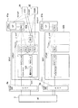
以下に、図面を参照しつつ本発明の実施例について説明する。図1は本発明の実施例の機能ブロック図であり、図12と同等部分は同一符号により示している。図1に示す如く、RNC4が、シグナリングを制御するCプレーンに相当するCプレーン制御装置(CPE:Control Plane Equipment )41と、ユーザデータを制御するUプレーンに相当するUプレーン制御装置(UPE:User Plane Equipment)42とに分離される構成である。
【0023】
全てのシグナリングは、各装置との間で、直接Cプレーン制御装置41内に設けられた中央制御装置(CP:Control Processor )16とやりとりが行われる。しかしながら、移動機(UE)2とRNC4との間のRRCシグナリングに関しては、CプレーンとUプレーンとに明確に分離することができないために、Uプレーン制御装置42内において、RLC131や132を終端した後、Cプレーン制御装置41内のRRC15へ転送するよう構成されている。
【0024】
こうすることにより、図12に示した既存のRNCのプロトコルレイヤアーキテクチャにおいて、L1として示される物理レイヤ(PHY)11はNode B(無線基地局装置)6に、L2として示されるデータリンクレイヤ12〜14はUプレーン制御装置42に、L3として示されるネットワークレイヤ15以上はCプレーン制御装置41に、それぞれ分離することができる。
【0025】
Cプレーン制御装置41内のRRC15からは、制御チャネルを提供するC−SAP(Control Service Access Point)を用いて、Node B内の物理レイヤ11、Uプレーン制御装置42内のMACレイヤ12、RLCレイヤ13及びBMCレイヤ14を終端する各装置が制御されるようになっている。また、Node B6とRNC4との間のシグナリングNBAP、RNC4と他のRNC内Cプレーン制御装置(CPE)43との間のシグナリングRNSAP、RNC4とMSC(Mobile Switching Center )31やSGSN(Serving GPRS(Global Packet Radio Service) Switching Node)32との間のシグナリングRANAPは、Cプレーン制御装置41内のCP16により直接終端して処理を行うものとする。
【0026】
なお、MSC31は回線交換機能を有し、SGSN32はパケット交換機能を有するものであり、図11に示したコアネットワーク(CN)3に含まれる。
【0027】
また、RNC4と移動機2との間で利用されるRRCシグナリングは、移動機2からNode B6、Uプレーン制御装置42内のMACレイヤ12及びRLCレイヤ13を経由して、Cプレーン制御装置41内のRRCレイヤ15で終端される。PCH/FACHに関しては、Node B6とUプレーン制御装置42との関係が、Logical O&M手順(物理的には、Node Bに実装されているリソースを、RNCがコントロールするためのシグナリングであり、3GPPの仕様書(25.401)にて規定)後に必ず固定され、局データを変更しない限り変更されることはないので、Uプレーン制御装置42内のMAC−c/shレイヤ121及びRLCレイヤ13で終端され、Cプレーン制御装置41へ送信される。
【0028】
ユーザデータを送信するDCH(個別チャネル:Dedicated Channel )に関しても、任意のNode BとUプレーン制御装置42とを接続することができ、Uプレーン制御装置42内で、複数のNode B間でパスの選択合成が、選択合成部123で行われた後、MAC−dレイヤ122及びRLCレイヤ13で終端され、Cプレーン制御装置41を介する回線交換機能を有するMSC31や、パケット交換機能を有するSGSN32へ送信される。
【0029】
なお、この選択合成部123は、ソフトハンドオーバ時において、複数のNode BからのDCHを選択合成し、これ等Node Bのなかから回線品質(受信品質)の最も良い回線を選んで、上位装置へ送出するものである。
【0030】
この様な図1に示した装置構成とすることにより、スケーラビリティに富んだシステム構成を組むことが可能となる。すなわち、シグナリングの処理能力を向上させる場合には、Cプレーン制御装置41のみを追加し、またユーザデータ転送速度を向上させる場合には、ユーザプレーン制御装置42のみを追加するようにすることができる。また、Uプレーン制御装置42内の各装置は、それぞれの装置間では関係を持たず、Cプレーン制御装置41内のRRC15により制御されるために、独立の装置として実装することも可能である。
【0031】
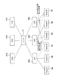
図2は、本発明の実施例に基づいて分離されたCプレーン制御装置(CPE)とUプレーン制御装置(UPE)との間のスケーラビリティを確保できることを説明するための図である。Cプレーン制御装置41a〜41cとUプレーン制御装置42a〜42cは、IPルータもしくはハブなどの装置17を介して、接続される。従来は、Cプレーン制御装置とUプレーン制御装置は一つのRNC装置であったために、増設単位はRNC単位でしかできなかった。しかしながら、Cプレーン制御装置は呼処理などのシグナリング処理を行っており、呼量が多くなると、処理能力が足りなくなる場合が考えられる。その際、Cプレーン制御装置を新たに追加することで、処理を容易に分散することができる。
【0032】
たとえば、2台のCプレーン制御装置41a,41bのとき、移動機の端末番号の下一桁が偶数であればCプレーン制御装置41aを、奇数であればCプレーン制御装置41bを、それぞれ利用すると決めていたアルゴリズムを、3台のCプレーン制御装置41a〜41cとして、端末番号の下一桁が0,1,2,3ならCプレーン制御装置41aを、4,5,6ならCプレーン制御装置41bを、7,8,9ならCプレーン制御装置41cを、それぞれ利用するように変更することによって、処理能力を約1.5倍に容易にできる。
【0033】
また、それとは別に、Uプレーン制御装置はユーザデータの転送を行っており、各移動機の転送する送受信データ量が多くなると、処理能力が足りなくなる場合が考えられる。その際、Uプレーン制御装置を新たに追加することで、処理を容易に分散することができる。たとえば、2台のUプレーン制御装置42a,42bでNode B6a〜6fを3台ずつ配下に接続していた構成を、3台のUプレーン制御装置42a〜42cでNode B6a〜6fを2台ずつ配下に接続することによって、転送速度を約1.5倍に増やすことが容易にできる。
【0034】
図3は、移動機である端末UE2がNode B6aとNode B6b間でソフトハンドオーバを行っている状態の図である。DCHは、Node B6aとNode B6bの双方から端末2へ接続される。Uプレーン制御装置42a内の選択合成部123における選択合成により、Node B6aと6bのうち、回線品質の良い回線が選ばれて上位装置へ送られる。
【0035】
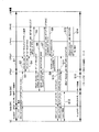
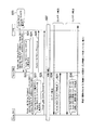
図4は、移動機である端末UEがNode B#1(6a)、Uプレーン制御装置(UPE)#1(42a)を利用して音声通信を行っている状態から(ステップS1)、Node B#2(6b)との間でソフトハンドオーバの要求を行い、端末UEとNode B#2間のパスを接続するまでのシーケンスである。Cプレーン制御装置(CPE)#1(41a)はUプレーン制御装置#1とNode B#1を、Cプレーン制御装置#2(41b)はUプレーン制御装置#2(42b)とNode B#2のリソース管理を行っている。
【0036】
ソフトハンドオーバの要求は、“MEASUREMENT REPORT(RRC)”として、端末UEからNode B#1、Uプレーン制御装置#1を経由して、Cプレーン制御装置#1に通知される(ステップS2)。Cプレーン制御装置#1はUプレーン制御装置#1に対するソフトハンドオーバ用のIPアドレスを取得し、“RADIO LINK SETUP REQUEST”と共に、Uプレーン制御装置#1へ通知する(ステップS3)。Uプレーン制御装置#1は、Cプレーン制御装置#1へ“RADIO LINK
SETUP RESPONSE ”により応答する(ステップS4)。
【0037】
次に、Cプレーン制御装置#1は、移動先Node B#2を管理するCプレーン制御装置#2へ“RADIO LINK SETUP REQUEST(RNSAP)”と共にソフトハンドオーバ用に取得したUプレーン制御装置#1のIPアドレスを送信し(ステップS5)、Cプレーン制御装置#2はNode B#2へ“RADIO LINK SETUP REQUEST(NBAP)”と共にソフトハンドオーバ用に取得したUプレーン制御装置#1のIPアドレスを送信する(ステップS6)。
【0038】
Node B#2は、Cプレーン制御装置#2へ“RADIO LINK SETUP RESPONSE (NBAP)”を通知する際に、Node B#2のIPアドレスを通知する(ステップS7)。次に、Cプレーン制御装置#2はCプレーン制御装置#1へ“RADIO LINK SETUP RESPONSE (RNSAP)”と共にNode B#2のIPアドレスを通知する(ステップS8)。Cプレーン制御装置#1は、Uプレーン制御装置#1に“RADIO LINK SETUP INDICATION ”によって、Node B#2のIPアドレスを通知する(ステップS9)。
【0039】
これらの手順により、Uプレーン制御装置#1にはNode B#2のIPアドレスが、Node B#2にはUプレーン制御装置#1のIPアドレスが、それぞれ通知され、ユーザデータの送受信ができる状態になる。それと同時に、Cプレーン制御装置#1は端末UEへ“ACTIVE SET UPDATE (RRC)”を通知する(ステップS10)。端末UEからCプレーン制御装置#1へ“ACTIVE SET UPDATE COMPLETE(RRC)”が通知されることにより(ステップS11)、端末UEとNode B#2間で無線同期が開始される(ステップS12)。
【0040】
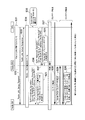
端末UEとNode B#2間の無線回線のレイヤ1(L1)同期が完了したあと、“RADIO LINK RESTORE INDICATION (NBAP)”がNode B#2からCプレーン制御装置#2へ通知される(ステップS13)。Cプレーン制御装置#2はCプレーン制御装置#1へ、“RADIO LINK RESTORE INDICATION (RNSAP)”を送信し(ステップS14)、端末UEとNode B#2間のパスは設定を完了し、Node B#1とNode B#2を経由して、一つのUプレーン制御装置#1に接続するソフトハンドオーバのパスが設定される(ステップS15)。
【0041】
このように、RNCをまたがるソフトハンドオーバの場合には、本発明では、従来のようにユーザデータに関してドリフトRNCとサービングRNCとの間にパスを設定することなく、一つのUプレーン制御装置から複数のNode Bへパスを接続することにより、ソフトハンドオーバが可能となるために、同じUプレーン制御装置を利用し続けることができ、RNC間のパスが不要になり、資源の有効利用が図れると共に、RNCを経由することによる遅延が防止されることにもなる。
【0042】
次に、RNCをCプレーン制御装置とUプレーン制御装置とに分離して、更に、Uプレーン制御装置をNode Bに組み込むという、変形例も考えられる。この場合、Node Bに組み込まれたUプレーン制御装置がユーザデータの選択合成を実行する機能(図1の選択合成部123)を持たない場合には、複数のNode Bを介したソフトハンドオーバが実行できなくなる。このことは無線区間にCDMAを用いることのメリットを放棄するといえる。そこで、個々のNode Bにユーザデータの選択合成を行なう機能を持たせ、Node B間での通信を行なうことが考えられる。
【0043】
まず、図5に、従来のネットワーク構成とユーザデータ、制御信号の流れを示す。このネットワーク構成では、複数のNode B6a〜6cを含む状態でソフトハンドオーバが行なわれているときは、SRNC(サービングRNC:Serving RNC )4bがユーザデータ、制御信号の終端を行なう。複数のRNCを含むソフトハンドオーバが行なわれているときには、インタフェースIurを介してDRNC(ドリフトRNC:Drift RNC )4aからSRNC4bにユーザデータ、制御信号が転送される。
【0044】
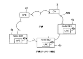
図6は、RNCがCプレーン制御装置42とUプレーン制御装置41とに分離され、かつUプレーン制御装置42a〜42cがNode B6a〜6cにそれぞれ組み込まれたときのネットワーク構成である。Node B6a〜6c、Cプレーン制御装置41、CN3がIP網100を介して接続されている。
【0045】
次に、図6で示されたIP網において、どのように複数のNode Bを含むハンドオーバが実行されるかを示す。ここでは、Cプレーン制御装置41が各Node BのIPアドレスを知っていると仮定する。
【0046】
図7は、端末UEが無線リンク(RL)を持っていない状態から2つのNode Bを介して無線リンク(RL)を設定する例である。Cプレーン制御装置(CPE)は複数のNode B(図7では、Node B#1とNode B#2)の中から、サービングノードとなるNode Bを選択する(図7では、Node B#1)(ステップS20)。Cプレーン制御装置は“Radio Link Setup Request”メッセージでサービングNode B(図7では、Node B#1)のIPアドレスと、その他のNode B(図7では、Node B#2)のIPアドレスを、両者の違いが分かるようにNode Bに通知する(ステップS21,22)。
【0047】
Cプレーン制御装置は最も品質の良いセルを制御しているNode BをサービングNode Bに指定する。Node Bは自ノードのIPアドレスとサービングNode BのIPアドレスとを比較して、自ノードのIPアドレスとサービングNode BのIPアドレスとが等しい場合は、自ノードがサービングNode Bであると認識する(ステップS22)。それ以外のNode Bは、サービングNode BのIPアドレスをUL(アップリンク)データの転送先として認識する(ステップS24)。
【0048】
各Node Bは無線リンクの設定に必要なリソースが確保できたら、Cプレーン制御装置に“Radio Link Setup Response ”メッセージを返信する(ステップS25,26)。その後、Uプレーンの同期の確立を実行する(ステップS27)。
【0049】
DL(ダウンリンク)のデータ転送の場合では(ステップS28)、サービングNode Bは“Radio Link Setup Request”メッセージで通知された他のNode BのIPアドレスにデータを転送する(ステップS29)。UL(アップリンク)のデータ転送の場合では、サービングNode Bは各Node Bから受信したデータを比較して、最も品質の良いものを上位に転送する(ステップS30)。
【0050】
図8は、移動機が既に無線リンクを持っている状態から、新たなNode Bを介して無線リンクを追加してソフトハンドオーバの状態になる例である。この場合は既に無線リンクが設定されているNode B(図8では、Node B#2)に(ステップS31)、サービングとなるNode BのIPアドレスとソフトハンドオーバに含まれるNode BのIPアドレスとを通知する必要がある。
【0051】
そこで、まず、新たなNode B(図8では、Node B#1)に対して、無線リンクを、“Radio Link Setup Request”メッセージ(ステップS32)及び“Radio Link Setup Response ”メッセージ(ステップS33)を使用して設定し(ステップS34)、その後ソフトハンドオーバに含まれる全てのNode BにサービングとなるNode BのIPアドレスとソフトハンドオーバに含まれるNode BのIPアドレスを通知する。
【0052】
このための手段として、新たに“Soft Handover Indication”メッセージを提案する(ステップS36,37)。このメッセージにサービングとなるNodeBのIPアドレスとソフトハンドオーバに含まれるNode BのIPアドレスが含まれる。その後の動作は図7と同様であり、同一符号を持って示している。
【0053】
図7、図8では、2つのNode Bを含むソフトハンドオーバを例としているが、ソフトハンドオーバに含まれるNode Bの数は2つ以上でも上記のメカニズムは適応可能である。この場合には、図7、図8におけるステップS36,37の“Other Node B IP address に複数のIPアドレスが設定されることになる。
【0054】
図9にIP網100でのユーザデータ、制御信号の流れを示す。図9は図7、図8のシーケンスと対応している。
【0055】
個々のNode Bに選択合成機能を持たせた場合の例を述べたが、個々のNode Bに選択合成機能を持たせると、Node Bの製造コストが高くなるという問題がある。そこで、複数のNode Bのなかから、ある一つのNode Bにのみ選択合成機能を持たせる構成も考えられる。この場合には、複数のNode Bを介したソフトハンドオーバでは、ユーザデータはこの選択合成機能を有するNode Bにより終端されるものとする。こうすることにより、CDMAの特徴であるソフトハンドオーバ機能を維持することができることになる。
【0056】
図10にNode B#1とNode B#2がソフトハンドオーバに含まれているが、Node B#1とNode B#2ともに選択合成を行なう機能を持たない場合のIP網100でのユーザデータ、制御信号の流れを示す。図10では、Node B#3(6c)が選択合成機能を有しているものとする。
【0057】
このような処理を実現するためには、CN3がIP網100に含まれる全てのNode BのIPアドレス、位置、選択合成機能の有無、負荷状況などの情報を知っていることが前提となる。図10の例では、CN3はNode B#1、Node B#2にサービング(Serving)となるNode BのIPアドレスを通知し、Node B#1、Node B#2はサービングとなるNode Bにデータを転送する。また、CN3はNode B#3に対して、サービングとして機能するよう指示を行う。
【0058】
ソフトハンドオーバに含まれているNode B以外からサービングNodeBを選択するときには、CN3は、ソフトハンドオーバに含まれるNode Bと、サービングノードとして機能するNode Bとの物理的な距離や、サービング対象となるNode Bの負荷状況を考慮するものとする。
【0059】
【発明の効果】
以上述べたように、本発明によれば、RNCをシグナリング制御装置のCプレーン制御装置とユーザデータ処理装置のUプレーン制御装置に分離したことにより、スケーラビリティに富んだシステム構成にすることができるという効果がある。また、Uプレーン制御装置内の各装置間を関連づけていないため、別々に実装することができる。
【0060】
更に、Cプレーン制御装置をまたがるソフトハンドオーバの時でも、同じUプレーン制御装置を利用し続けることができ、RNCとRNCを接続する従来の接続パスが不要になり、また、RNCを経由することによる遅延をなくすことができるという効果がある。
【0061】
更にはまた、Node Bに現状のRNCで行なわれているユーザデータの終端機能が組み込まれて、そのNode BがIP網に接続されている場合でも、あるNode Bにユーザデータの選択合成機能を持たせることにより、複数のNode Bを含んだソフトハンドオーバを実行できるという効果がある。
【図面の簡単な説明】
【図1】本発明の実施例の機能ブロック図である。
【図2】本発明の実施例の効果を説明するための図である。
【図3】本発明の実施例を使用した場合のソフトハンドオーバ時の状態を説明するための図である。
【図4】本発明の実施例におけるソフトハンドオーバ時のパス接続シーケンス図である。
【図5】既存(従来)のネットワーク構成とユーザデータ、制御信号の流れを示す図である。
【図6】本発明の実施例を使用したIP網のネットワーク構成を示す図である。
【図7】同時に複数のNode Bに無線リンクを設定する場合の、本発明の実施例のシーケンス図である。
【図8】新たなNode Bに無線リンクを追加設定する場合の、本発明の実施例のシーケンス図である。
【図9】本発明の実施例におけるIP網でのユーザデータ、制御信号の流れの例を示す図である。
【図10】本発明の実施例におけるIP網でのユーザデータ、制御信号の流れの他の例を示す図である。
【図11】W−CDMA通信方式のシステムアーキテクチャを示す図である。
【図12】図11のシステムアーキテクチャをプロトコルアーキテクチャとして示す図である。
【符号の説明】
1 無線アクセスネットワーク(RAN)
2 移動機(UE)
3 コアネットワーク(CN)
4 無線制御装置(RNC)
6 Node B(ノードB:無線基地局装置)
11 物理層(PHY)
12 MACサブレイヤ
13 RLCサブレイヤ
14 BMCサブレイヤ
15 RRCレイヤ
16 中央制御装置(CP)
17 ルータ
31 MSC(Mobile Switching Center )
32 SGSN(Serving GPRS Switching Node )
41 C(コントロール)プレーン制御装置(CPE)
42 U(ユーザ)プレーン制御装置(UPE)[0001]
BACKGROUND OF THE INVENTION
The present invention relates to a radio access network apparatus and a mobile communication system using the same, and more particularly to improvement of a radio network controller (RNC) in a W-CDMA cellular mobile communication system.
[0002]
[Prior art]
An architecture of a W-CDMA communication system which is a mobile communication system is shown in FIG. The radio access network (RAN) 1 is composed of radio control devices (RNCs) 4 and 5 and Node Bs (
[0003]
The interface between Node B and RNC is called Iub, and an Iur interface is also defined as an interface between RNCs. Each Node B covers one or a plurality of
[0004]
FIG. 12 shows a protocol architecture of a radio interface in the W-CDMA communication system shown in FIG. As shown in FIG. 12, this protocol architecture includes a physical layer (PHY) 11 indicated as L1,
[0005]
The data link layer of L2 is divided into three sub-layers including a MAC (Media Access Control)
[0006]
The ellipses in FIG. 12 indicate service access points (SAP) between layers or between sublayers, and the SAP between the
[0007]
Examples of this logical channel include CCCH (Common Control Channel), PCCH (Paging Control Channel), BCCH (Broadcast Control Channel), and CTCH (Common Traffic Channel).
[0008]
The SAP between the
[0009]
Examples of this transport channel include PCH (Paging Channel), DCH (Dedicated Channel), BCH (Broadcast Channel), and FACH (Forward Access Channel).
[0010]
The
[0011]
In FIG. 12, there are a C (Control) plane for signaling for transferring control signals and a U (User) plane for transferring user data, and the BMC
[0012]
[Problems to be solved by the invention]
In the
[0013]
In a mobile communication system having a conventional RNC in which both U-plane and C-plane control functions are integrated, only the C-plane control function is added to improve the signaling processing capability. Nevertheless, it is necessary to add the RNC itself, and when it is desired to improve the transfer rate of user data, it is only necessary to add the control function of the U plane. It is necessary to add itself. Therefore, it is difficult to construct a highly scalable system with the conventional RNC configuration.
[0014]
Moreover, there are the following problems at the time of soft handover. That is, at the time of normal call setup, one radio link (Radio Link) is connected between the RNC and the Node B, but when the UE (mobile device) moves and enters the soft handover state, the RNC And more than one Node B are connected to two or more paths. When a soft handover state is reached across RNCs, a path is connected using an interface called Iur (see FIG. 11) between the serving RNC and the drift RNC.
[0015]
In such a soft handover state across RNCs, a serving RNC and a drift RNC can be connected to a plurality of Node Bs in soft handover from one U-plane control function unit even though a user data path can be connected. Therefore, it is necessary to connect a path therefor, which is not only a waste of resources, but also has a disadvantage that a delay occurs through the RNC.
[0016]
An object of the present invention is to provide a radio access network apparatus capable of constructing a highly scalable system and a mobile communication system using the same.
[0017]
Another object of the present invention is to provide a radio access network apparatus that saves resources and does not cause a delay during a soft handover, and a mobile communication system using the same.
[0018]
[Means for Solving the Problems]
A radio access network apparatus according to the present invention is a radio access network apparatus provided between a mobile terminal in a mobile communication system and an upper apparatus that is an exchange network, and connected to the mobile terminal via a radio interface, A user plane control unit that controls transfer of user data related to a mobile terminal, and a control plane control unit that controls transfer of signaling that is a control signal, wherein the user plane control unit and the control plane control unit are physically The user plane control means is incorporated in a radio base station. And having a function of terminating the data link layer which is the protocol of the radio interface It is characterized by that.
[0019]
And Above The control plane control means has a function of terminating a network layer that is a protocol of the radio interface. Further, the user data is controlled to be transferred between the mobile terminal and the higher-level device via the data link layer of the user plane control means, and the signaling is performed by the data link layer and the control of the user plane control means. Transfer control is performed via the network layer of the plane control means.
[0020]
Furthermore, the Wireless base station Has a function to terminate the physical layer which is the protocol of the radio interface. To do Features. Further, the user plane control means selects means for selecting the user data having a good reception quality from the plurality of radio base stations in a soft handover state, and sending the selected user data to the upper apparatus. including That features And And The mobile communication system is a W-CDMA cellular system.
[0021]
A mobile communication system according to the present invention includes the radio access network device.
[0022]
DETAILED DESCRIPTION OF THE INVENTION
Embodiments of the present invention will be described below with reference to the drawings. FIG. 1 is a functional block diagram of an embodiment of the present invention, and the same parts as those in FIG. 12 are denoted by the same reference numerals. As shown in FIG. 1, the RNC 4 controls a C plane control device (CPE: Control Plane Equipment) 41 corresponding to a C plane that controls signaling, and a U plane control device (UPE: User) that corresponds to a U plane that controls user data. Plane Equipment) 42.
[0023]
All signaling is directly exchanged with a central control device (CP: Control Processor) 16 provided in the C-
[0024]
By doing so, in the protocol layer architecture of the existing RNC shown in FIG. 12, the physical layer (PHY) 11 shown as L1 is transferred to the Node B (radio base station apparatus) 6 and the data link layers 12 to 12 shown as L2. 14 can be separated into the
[0025]
From the
[0026]
The
[0027]
Further, RRC signaling used between the RNC 4 and the
[0028]
With respect to DCH (Dedicated Channel) for transmitting user data, any Node B and U
[0029]
The
[0030]
By adopting such an apparatus configuration shown in FIG. 1, it is possible to build a system configuration with high scalability. That is, when the signaling processing capability is improved, only the C
[0031]
FIG. 2 is a diagram for explaining that it is possible to ensure scalability between the C-plane control device (CPE) and the U-plane control device (UPE) separated according to the embodiment of the present invention. The C
[0032]
For example, in the case of two C-
[0033]
Separately, the U-plane control device transfers user data, and if the amount of transmission / reception data transferred by each mobile device increases, the processing capability may be insufficient. At that time, the processing can be easily distributed by newly adding a U-plane control device. For example, a configuration in which three
[0034]
FIG. 3 is a diagram illustrating a state in which the terminal UE2 that is a mobile device is performing a soft handover between the
[0035]
FIG. 4 shows a state in which the mobile terminal UE performs voice communication using Node B # 1 (6a) and U-plane control device (UPE) # 1 (42a) (Step S1). This is a sequence from a request for soft handover to # 2 (6b) to connection of a path between the terminal UE and
[0036]
The soft handover request is notified as “MEASUREMENT REPORT (RRC)” from the terminal UE to the C plane
A response is made by "SETUP RESPONSE""(step S4).
[0037]
Next, the C-plane
[0038]
The
[0039]
Through these procedures, the U-plane
[0040]
After completing the layer 1 (L1) synchronization of the radio channel between the terminal UE and the
[0041]
Thus, in the case of soft handover across RNCs, the present invention does not set a path between a drift RNC and a serving RNC with respect to user data as in the prior art, and a plurality of multiple UNCs from a single U-plane controller. By connecting the path to the Node B, soft handover is possible, so that the same U-plane control device can be used continuously, the path between the RNCs becomes unnecessary, the resources can be used effectively, and the RNC This also prevents a delay caused by going through.
[0042]
Next, a modification in which the RNC is separated into a C plane control device and a U plane control device, and the U plane control device is incorporated into the Node B is also conceivable. In this case, if the U-plane control device incorporated in Node B does not have a function (selective combining
[0043]
First, FIG. 5 shows a conventional network configuration, user data, and control signal flow. In this network configuration, when soft handover is performed in a state including a plurality of
[0044]
FIG. 6 shows a network configuration when the RNC is separated into the C-
[0045]
Next, how the handover including a plurality of Node Bs is executed in the IP network shown in FIG. Here, it is assumed that the C-
[0046]
FIG. 7 is an example in which a radio link (RL) is set via two Node Bs from a state in which the terminal UE does not have a radio link (RL). The C-plane control device (CPE) selects a Node B serving as a serving node from a plurality of Node Bs (
[0047]
The C plane control apparatus designates the Node B that controls the cell with the highest quality as the serving Node B. The Node B compares the IP address of its own node with the IP address of the serving Node B, and recognizes that its own node is the serving Node B when the IP address of its own node and the IP address of the serving Node B are equal. (Step S22). The other Node Bs recognize the serving Node B IP address as the UL (uplink) data transfer destination (step S24).
[0048]
When each Node B has secured the resources necessary for setting up the radio link, it returns a “Radio Link Setup Response” message to the C-plane control device (steps S25 and S26). Thereafter, establishment of U-plane synchronization is executed (step S27).
[0049]
In the case of DL (downlink) data transfer (step S28), the serving Node B transfers data to the IP address of the other Node B notified by the “Radio Link Setup Request” message (step S29). In the case of UL (uplink) data transfer, the serving Node B compares the data received from each Node B, and transfers the data with the highest quality to the upper level (step S30).
[0050]
FIG. 8 is an example in which a mobile station enters a soft handover state by adding a wireless link via a new Node B from a state where the mobile device already has a wireless link. In this case, the Node B (
[0051]
Therefore, first, for the new Node B (
[0052]
As a means for this, a new “Soft Handover Indication” message is proposed (steps S36 and S37). This message includes the serving Node B IP address and the Node B IP address included in the soft handover. Subsequent operations are the same as those in FIG. 7, and are denoted by the same reference numerals.
[0053]
7 and 8 exemplify a soft handover including two Node Bs, but the above mechanism can be applied even if the number of Node Bs included in the soft handover is two or more. In this case, a plurality of IP addresses are set in “Other Node B IP address” in steps S36 and S37 in FIGS.
[0054]
FIG. 9 shows the flow of user data and control signals in the
[0055]
An example in which each node B has a selective combining function has been described. However, if each node B has a selective combining function, there is a problem that the manufacturing cost of the Node B increases. Therefore, a configuration in which only one Node B among the plurality of Node Bs has a selective combining function is also conceivable. In this case, in soft handover through a plurality of Node Bs, user data is assumed to be terminated by the Node B having this selective combining function. By doing so, the soft handover function, which is a feature of CDMA, can be maintained.
[0056]
Although
[0057]
In order to realize such processing, it is assumed that the
[0058]
When selecting a serving NodeB from a node other than the Node B included in the soft handover, the
[0059]
【The invention's effect】
As described above, according to the present invention, the RNC is separated into the C plane control device of the signaling control device and the U plane control device of the user data processing device, so that a highly scalable system configuration can be achieved. effective. Moreover, since each apparatus in a U plane control apparatus is not linked | related, it can mount separately.
[0060]
Furthermore, even during soft handover across C plane control devices, the same U plane control device can continue to be used, and the conventional connection path for connecting the RNC and RNC is no longer necessary. There is an effect that the delay can be eliminated.
[0061]
Furthermore, even when the termination function of user data performed in the current RNC is incorporated in the Node B and the Node B is connected to the IP network, the function of selecting and synthesizing user data in a certain Node B is provided. By providing, there is an effect that a soft handover including a plurality of Node Bs can be executed.
[Brief description of the drawings]
FIG. 1 is a functional block diagram of an embodiment of the present invention.
FIG. 2 is a diagram for explaining the effect of the embodiment of the present invention.
FIG. 3 is a diagram for explaining a state at the time of soft handover when the embodiment of the present invention is used.
FIG. 4 is a path connection sequence diagram at the time of soft handover in the embodiment of the present invention.
FIG. 5 is a diagram showing an existing (conventional) network configuration and the flow of user data and control signals.
FIG. 6 is a diagram showing a network configuration of an IP network using an embodiment of the present invention.
FIG. 7 is a sequence diagram of an embodiment of the present invention in the case where radio links are simultaneously set for a plurality of Node Bs.
FIG. 8 is a sequence diagram of an embodiment of the present invention when a radio link is additionally set to a new Node B.
FIG. 9 is a diagram showing an example of the flow of user data and control signals in the IP network in the embodiment of the present invention.
FIG. 10 is a diagram showing another example of user data and control signal flows in the IP network according to the embodiment of the present invention.
FIG. 11 is a diagram showing a system architecture of a W-CDMA communication system.
FIG. 12 is a diagram illustrating the system architecture of FIG. 11 as a protocol architecture.
[Explanation of symbols]
1 Radio access network (RAN)
2 Mobile equipment (UE)
3 Core network (CN)
4 Radio control unit (RNC)
6 Node B (Node B: Radio base station device)
11 Physical layer (PHY)
12 MAC sublayer
13 RLC sublayer
14 BMC sublayer
15 RRC layer
16 Central control unit (CP)
17 router
31 MSC (Mobile Switching Center)
32 SGSN (Serving GPRS Switching Node)
41 C (control) plane control equipment (CPE)
42 U (User) Plane Control Unit (UPE)
Claims (12)
前記移動端末に関するユーザデータの転送制御をなすユーザプレーン制御手段と、
制御信号であるシグナリングの転送制御をなすコントロールプレーン制御手段とを含み、
前記ユーザプレーン制御手段と前記コントロールプレーン制御手段とが物理的に分離して設けられており、
前記ユーザプレーン制御手段は、無線基地局に組み込まれており、かつ前記無線インタフェースのプロトコルであるデータリンクレイヤを終端する機能を有することを特徴とする無線アクセスネットワーク装置。A radio access network apparatus provided between a mobile terminal in a mobile communication system and an upper apparatus that is an exchange network, and connected to the mobile terminal via a radio interface,
User plane control means for performing transfer control of user data related to the mobile terminal;
Control plane control means for performing transfer control of signaling that is a control signal,
The user plane control means and the control plane control means are provided physically separated,
The user plane controlling means, the radio access network apparatus, characterized in that it have a function of terminating a data link layer which is built into the radio base station, and the radio interface protocol.
前記無線アクセスネットワーク装置は、
前記移動端末に関するユーザデータの転送制御をなすユーザプレーン制御手段と、
制御信号であるシグナリングの転送制御をなすコントロールプレーン制御手段とを含み、
前記ユーザプレーン制御手段と前記コントロールプレーン制御手段とが物理的に分離して設けられており、
前記ユーザプレーン制御手段は、無線基地局に組み込まれており、かつ前記無線インタフェースのプロトコルであるデータリンクレイヤを終端する機能を有することを特徴とする移動通信システム。A mobile communication system that includes a mobile terminal, a host device that is an exchange network, and a radio access network device that is provided between the mobile terminal and the host device and is connected to the mobile terminal via a radio interface. And
The radio access network device is:
User plane control means for performing transfer control of user data related to the mobile terminal;
Control plane control means for performing transfer control of signaling that is a control signal,
The user plane control means and the control plane control means are provided physically separated,
The user plane controlling means, the mobile communication system characterized in that you have the ability to terminate the data link layer is built into the radio base station, and the radio interface protocol.
Priority Applications (10)
| Application Number | Priority Date | Filing Date | Title |
|---|---|---|---|
| JP2002154889A JP4172207B2 (en) | 2002-05-29 | 2002-05-29 | Radio access network apparatus and mobile communication system using the same |
| EP06112237A EP1679912A3 (en) | 2002-05-29 | 2003-05-19 | Radio access network apparatus and mobile communication system using the same |
| EP08159491.3A EP1973354B1 (en) | 2002-05-29 | 2003-05-19 | User plane and control plane split in radio access network |
| EP03011357A EP1367841A3 (en) | 2002-05-29 | 2003-05-19 | Radio access network apparatus and mobile communication system using the same |
| US10/441,185 US7164917B2 (en) | 2002-05-29 | 2003-05-20 | Radio access network apparatus and mobile communication system using the same |
| KR1020030033963A KR100594523B1 (en) | 2002-05-29 | 2003-05-28 | Radio access network device and mobile communication system using same |
| KR1020050109753A KR100630401B1 (en) | 2002-05-29 | 2005-11-16 | Radio access network apparatus and mobile communication system using the same |
| US11/524,749 US7693524B2 (en) | 2002-05-29 | 2006-09-21 | Radio access network apparatus and mobile communication system using the same |
| JP2008116532A JP4973588B2 (en) | 2002-05-29 | 2008-04-28 | Mobile communication system |
| JP2011185415A JP5273223B2 (en) | 2002-05-29 | 2011-08-29 | Mobile communication system, communication method therefor, and radio base station apparatus |
Applications Claiming Priority (1)
| Application Number | Priority Date | Filing Date | Title |
|---|---|---|---|
| JP2002154889A JP4172207B2 (en) | 2002-05-29 | 2002-05-29 | Radio access network apparatus and mobile communication system using the same |
Related Child Applications (1)
| Application Number | Title | Priority Date | Filing Date |
|---|---|---|---|
| JP2008116532A Division JP4973588B2 (en) | 2002-05-29 | 2008-04-28 | Mobile communication system |
Publications (2)
| Publication Number | Publication Date |
|---|---|
| JP2003348661A JP2003348661A (en) | 2003-12-05 |
| JP4172207B2 true JP4172207B2 (en) | 2008-10-29 |
Family
ID=29417181
Family Applications (3)
| Application Number | Title | Priority Date | Filing Date |
|---|---|---|---|
| JP2002154889A Expired - Fee Related JP4172207B2 (en) | 2002-05-29 | 2002-05-29 | Radio access network apparatus and mobile communication system using the same |
| JP2008116532A Expired - Lifetime JP4973588B2 (en) | 2002-05-29 | 2008-04-28 | Mobile communication system |
| JP2011185415A Expired - Fee Related JP5273223B2 (en) | 2002-05-29 | 2011-08-29 | Mobile communication system, communication method therefor, and radio base station apparatus |
Family Applications After (2)
| Application Number | Title | Priority Date | Filing Date |
|---|---|---|---|
| JP2008116532A Expired - Lifetime JP4973588B2 (en) | 2002-05-29 | 2008-04-28 | Mobile communication system |
| JP2011185415A Expired - Fee Related JP5273223B2 (en) | 2002-05-29 | 2011-08-29 | Mobile communication system, communication method therefor, and radio base station apparatus |
Country Status (4)
| Country | Link |
|---|---|
| US (2) | US7164917B2 (en) |
| EP (3) | EP1679912A3 (en) |
| JP (3) | JP4172207B2 (en) |
| KR (2) | KR100594523B1 (en) |
Families Citing this family (48)
| Publication number | Priority date | Publication date | Assignee | Title |
|---|---|---|---|---|
| CN1315341C (en) * | 2001-02-15 | 2007-05-09 | 诺基亚公司 | Method and system for managing mobile unit to network connection |
| JP4091409B2 (en) | 2002-12-02 | 2008-05-28 | 株式会社エヌ・ティ・ティ・ドコモ | Wireless communication method and wireless access network system |
| JP3972198B2 (en) | 2002-12-12 | 2007-09-05 | 日本電気株式会社 | Cell information setting method, radio access network, and radio control apparatus |
| JP4206742B2 (en) * | 2002-12-12 | 2009-01-14 | 日本電気株式会社 | Radio control apparatus, mobile communication system using the same, and operation control method thereof |
| JP3988043B2 (en) | 2002-12-12 | 2007-10-10 | 日本電気株式会社 | Radio access network control method and radio access network |
| CN1729657B (en) * | 2003-04-11 | 2010-04-21 | 富士通株式会社 | Mobile communication system and data distribution method in the same |
| WO2004093481A1 (en) * | 2003-04-14 | 2004-10-28 | Nec Corporation | Mobile communication system, radio base station containing control device in the mobile communication system and control method thereof |
| US7248873B2 (en) * | 2003-06-25 | 2007-07-24 | Nokia Corporation | Parameter selection optimization for handover |
| US7983716B2 (en) * | 2003-09-30 | 2011-07-19 | Interdigital Technology Corporation | Centralized radio network controller |
| US7460513B2 (en) | 2003-11-17 | 2008-12-02 | Telefonaktiebolaget Lm Ericsson (Publ) | Encapsulation of diverse protocols over internal interface of distributed radio base station |
| US7856029B2 (en) | 2003-11-17 | 2010-12-21 | Telefonaktiebolaget Lm Ericsson (Publ) | Pre-start-up procedure for internal interface of distributed radio base station |
| US7529215B2 (en) * | 2003-11-17 | 2009-05-05 | Telefonaktiebolaget Lm Ericsson (Publ) | Encapsulation of independent transmissions over internal interface of distributed radio base station |
| JP4534492B2 (en) | 2004-01-14 | 2010-09-01 | 日本電気株式会社 | Radio network controller and mobile communication system using the same |
| KR100800797B1 (en) * | 2004-01-28 | 2008-02-04 | 삼성전자주식회사 | Data transmission and reception method in communication system |
| US20050213541A1 (en) * | 2004-02-13 | 2005-09-29 | Lg Electronics Inc. | Method for transmitting service information between network nodes for MBMS service in mobile communication system |
| EP1583292A1 (en) * | 2004-03-30 | 2005-10-05 | Matsushita Electric Industrial Co., Ltd. | Delayed base station relocation in distributed radio access networks |
| JP3840480B2 (en) * | 2004-04-28 | 2006-11-01 | 松下電器産業株式会社 | Control station apparatus and base station apparatus |
| US20050250511A1 (en) * | 2004-05-05 | 2005-11-10 | Weimin Xiao | Method for rate control signaling to facilitate UE uplink data transfer |
| JP4609125B2 (en) * | 2004-05-06 | 2011-01-12 | 日本電気株式会社 | Data transfer system and method |
| JP4642384B2 (en) * | 2004-06-03 | 2011-03-02 | パナソニック株式会社 | Wireless network control system, wireless network control device, and base station |
| JP4474215B2 (en) * | 2004-06-29 | 2010-06-02 | パナソニック株式会社 | Radio base station apparatus, radio control system, and operation control method |
| GB0418281D0 (en) * | 2004-08-16 | 2004-09-15 | Nokia Corp | Communication system |
| JP4563231B2 (en) * | 2005-03-28 | 2010-10-13 | 三菱電機株式会社 | Wireless base station concentrator |
| WO2006129603A1 (en) * | 2005-05-30 | 2006-12-07 | Softbank Bb Corp. | Communication control system and communication control method |
| JP2009505461A (en) * | 2005-08-09 | 2009-02-05 | フリースケール セミコンダクター インコーポレイテッド | Handover based on quality of service metric obtained from MAC layer of received signal |
| US20090207790A1 (en) * | 2005-10-27 | 2009-08-20 | Qualcomm Incorporated | Method and apparatus for settingtuneawaystatus in an open state in wireless communication system |
| KR100658566B1 (en) | 2005-12-09 | 2006-12-15 | 한국전자통신연구원 | Multi-system terminal and its service adaptation device and method |
| JP4760531B2 (en) | 2006-05-26 | 2011-08-31 | 日本電気株式会社 | Mobile communication system, radio base station control device, and operation control method |
| JP2008005074A (en) * | 2006-06-21 | 2008-01-10 | Nec Corp | Wireless network system, wireless base station, and handover control method used therefor |
| JP4983283B2 (en) | 2006-08-17 | 2012-07-25 | 日本電気株式会社 | Mobile communication system, core network device, and mobile communication terminal |
| JP4995202B2 (en) | 2006-11-16 | 2012-08-08 | 株式会社エヌ・ティ・ティ・ドコモ | Communication control device and communication control method |
| CN101212786B (en) * | 2006-12-26 | 2011-02-16 | 华为技术有限公司 | System, method, and device for determining the algorithm on subscriber plane |
| US8077658B2 (en) * | 2007-10-01 | 2011-12-13 | Microsoft Corporation | Packet forwarding in multi-radio multi-hop wireless networks |
| EP2114101A1 (en) * | 2008-05-02 | 2009-11-04 | Nokia Siemens Networks Oy | A method and a controller for providing a continuous real time service |
| US8364842B2 (en) * | 2009-03-13 | 2013-01-29 | Novell, Inc. | System and method for reduced cloud IP address utilization |
| CN102273263A (en) | 2009-01-06 | 2011-12-07 | 夏普株式会社 | mobile communication system, QoS control station, and mobile station |
| WO2010101504A1 (en) * | 2009-03-05 | 2010-09-10 | Telefonaktiebolaget L M Ericsson (Publ) | Robust data transmission |
| JP5048746B2 (en) | 2009-12-09 | 2012-10-17 | シャープ株式会社 | Communication system, mobile station apparatus, radio link state management method, and integrated circuit |
| JP2012257091A (en) * | 2011-06-09 | 2012-12-27 | Fujitsu Ltd | Mobile communication system, base station device, and baseband processing allocation method |
| CN103533589B (en) | 2012-07-04 | 2018-03-13 | 华为技术有限公司 | A kind of method for switching network, system and network side equipment |
| JP6221716B2 (en) * | 2013-12-11 | 2017-11-01 | 富士通株式会社 | Communication system and network device |
| US20180192325A1 (en) * | 2015-06-30 | 2018-07-05 | Telefonaktiebolaget Lm Ericsson (Publ) | Dynamic mobile network architecture |
| WO2017004771A1 (en) | 2015-07-06 | 2017-01-12 | 华为技术有限公司 | Enhanced multimedia broadcast and multicast service embms system and management method therefor |
| EP3351036B1 (en) * | 2015-09-16 | 2021-06-02 | Nokia Solutions and Networks Oy | Control and user plane decoupling in radio access network |
| CN108886822B (en) * | 2016-07-04 | 2021-10-01 | 华为技术有限公司 | Method and device for transmitting data |
| CN110475353B (en) * | 2018-05-11 | 2022-06-28 | 华为技术有限公司 | Method and apparatus for link recovery |
| US11349557B2 (en) | 2018-11-30 | 2022-05-31 | At&T Intellectual Property I, L.P. | System model and architecture for mobile integrated access and backhaul in advanced networks |
| CN113785619B (en) * | 2020-04-29 | 2022-12-27 | 华为技术有限公司 | Access method and device and communication system |
Family Cites Families (32)
| Publication number | Priority date | Publication date | Assignee | Title |
|---|---|---|---|---|
| CN101141799B (en) | 1997-04-24 | 2011-06-22 | 株式会社Ntt都科摩 | Method and system for mobile communications |
| US6085108A (en) * | 1997-12-15 | 2000-07-04 | Telefonaktiebolaget Lm Ericsson | Modified downlink power control during macrodiversity |
| US6895245B2 (en) * | 1998-03-06 | 2005-05-17 | Telefonaktiebolaget Lm Ericssion(Publ) | Telecommunications interexchange measurement transfer |
| US6321092B1 (en) * | 1998-11-03 | 2001-11-20 | Signal Soft Corporation | Multiple input data management for wireless location-based applications |
| US6724756B2 (en) * | 1999-01-12 | 2004-04-20 | Cisco Technology, Inc. | Method for introducing switched virtual connection call redundancy in asynchronous transfer mode networks |
| US6879832B1 (en) * | 1999-02-26 | 2005-04-12 | Telefonaktiebolaget Lm Ericsson (Publ) | Method and apparatus for transferring information between mobile terminals and entities in a radio access network |
| US7072656B2 (en) * | 1999-03-16 | 2006-07-04 | Telefonaktiebolaget Lm Ericsson (Publ) | Handover in a shared radio access network environment using subscriber-dependent neighbor cell lists |
| US6519461B1 (en) * | 1999-10-29 | 2003-02-11 | Telefonaktiebolaget Lm Ericsson (Publ) | Channel-type switching from a common channel to a dedicated channel based on common channel load |
| GB2356770A (en) * | 1999-11-23 | 2001-05-30 | Ericsson Telefon Ab L M | SRNS relocation in a UMTS network |
| WO2001058086A2 (en) * | 2000-01-31 | 2001-08-09 | Telefonaktiebolaget Lm Ericsson (Publ) | Base station system architecture |
| US6996092B1 (en) * | 2000-01-31 | 2006-02-07 | Telefonaktiebolaget Lm Ericsson (Publ) | IP-based base station system |
| DE60030404T2 (en) * | 2000-02-22 | 2007-02-22 | Lucent Technologies Inc. | Procedures for passing on real-time connections in wireless communication systems |
| US6760303B1 (en) * | 2000-03-29 | 2004-07-06 | Telefonaktiebolaget Lm Ericsson (Publ) | Channel-type switching based on cell load |
| US6961571B1 (en) * | 2000-04-05 | 2005-11-01 | Telefonaktiebolaget Lm Ericsson (Publ) | Relocation of serving radio network controller with signaling of linking of dedicated transport channels |
| US6829482B2 (en) * | 2000-05-16 | 2004-12-07 | Telefonaktiebolaget Lm Ericsson (Publ) | Switching from dedicated to common channels when radio resources are controlled by drift radio network |
| FR2809576B1 (en) * | 2000-05-23 | 2002-11-15 | Nortel Matra Cellular | METHOD FOR CONTROLLING A CHANNEL BETWEEN A RADIO TERMINAL AND A CELLULAR RADIO COMMUNICATION INFRASTRUCTURE, AND ACCESS NETWORK IMPLEMENTING SUCH A METHOD |
| GB0015715D0 (en) * | 2000-06-27 | 2000-08-16 | Nokia Networks Oy | Maintaining association in a communications network |
| US6650905B1 (en) * | 2000-06-30 | 2003-11-18 | Nokia Mobile Phones, Ltd. | Universal mobile telecommunications system (UMTS) terrestrial radio access (UTRA) frequency division duplex (FDD) downlink shared channel (DSCH) power control in soft handover |
| US7027828B2 (en) * | 2000-11-18 | 2006-04-11 | Lg Electronics Inc. | Method for controlling power of TFCI field for DSCH in 3G standard mobile communication system |
| US6889050B1 (en) * | 2000-11-22 | 2005-05-03 | Telefonaktiebolaget Lm Ericsson (Publ) | Variable transmission rate services in a radio access network |
| US6944462B2 (en) * | 2000-12-11 | 2005-09-13 | Telefonaktiebolaget Lm Ericsson (Publ) | Control node handover in radio access network |
| US6912390B2 (en) * | 2000-12-22 | 2005-06-28 | Telefonaktiebolaget Lm Ericsson | Connection handling in SRNC relocation |
| GB2371177B (en) * | 2001-01-16 | 2003-02-19 | Ericsson Telefon Ab L M | Automatic repetition request mechanism in a radio access network |
| US6862450B2 (en) * | 2001-02-07 | 2005-03-01 | Nokia Mobile Phones Ltd. | Resetting signaling link upon SRNS relocation procedure |
| US7184710B2 (en) * | 2001-02-13 | 2007-02-27 | Telefonaktiebolaget Lm Ericsson (Publ) | Transmission of filtering/filtered information over the lur interface |
| US6970716B2 (en) * | 2001-02-22 | 2005-11-29 | Telefonaktiebolaget Lm Ericsson (Publ) | Power control for downlink shared channel in radio access telecommunications network |
| US6850759B2 (en) * | 2001-02-22 | 2005-02-01 | Telefonaktiebolaget Lm Ericsson (Publ) | Reducing signaling in RNSAP protocol upon cell change in cellular telecommunications network |
| US6954441B2 (en) * | 2001-07-12 | 2005-10-11 | Telefonaktiebolaget Lm Ericsson (Publ) | IP-based GSM and UMTS system |
| US6950398B2 (en) * | 2001-08-22 | 2005-09-27 | Nokia, Inc. | IP/MPLS-based transport scheme in 3G radio access networks |
| US7054294B2 (en) * | 2001-11-29 | 2006-05-30 | Telefonaktiebolaget Lm Ericsson (Publ) | Orthogonal variable spreading code (OVSF) allocation telecommunications network |
| KR100747464B1 (en) * | 2002-01-05 | 2007-08-09 | 엘지전자 주식회사 | Deadlock avoidance method using timer for high speed downlink packet connection (HSDPA) system |
| US7177658B2 (en) * | 2002-05-06 | 2007-02-13 | Qualcomm, Incorporated | Multi-media broadcast and multicast service (MBMS) in a wireless communications system |
-
2002
- 2002-05-29 JP JP2002154889A patent/JP4172207B2/en not_active Expired - Fee Related
-
2003
- 2003-05-19 EP EP06112237A patent/EP1679912A3/en not_active Withdrawn
- 2003-05-19 EP EP08159491.3A patent/EP1973354B1/en not_active Expired - Lifetime
- 2003-05-19 EP EP03011357A patent/EP1367841A3/en not_active Withdrawn
- 2003-05-20 US US10/441,185 patent/US7164917B2/en not_active Expired - Fee Related
- 2003-05-28 KR KR1020030033963A patent/KR100594523B1/en not_active Expired - Fee Related
-
2005
- 2005-11-16 KR KR1020050109753A patent/KR100630401B1/en not_active Expired - Fee Related
-
2006
- 2006-09-21 US US11/524,749 patent/US7693524B2/en not_active Expired - Lifetime
-
2008
- 2008-04-28 JP JP2008116532A patent/JP4973588B2/en not_active Expired - Lifetime
-
2011
- 2011-08-29 JP JP2011185415A patent/JP5273223B2/en not_active Expired - Fee Related
Also Published As
| Publication number | Publication date |
|---|---|
| EP1679912A2 (en) | 2006-07-12 |
| EP1973354A2 (en) | 2008-09-24 |
| EP1679912A3 (en) | 2006-07-26 |
| EP1367841A2 (en) | 2003-12-03 |
| US7693524B2 (en) | 2010-04-06 |
| EP1973354A3 (en) | 2009-07-01 |
| KR100630401B1 (en) | 2006-10-04 |
| EP1367841A3 (en) | 2003-12-10 |
| US7164917B2 (en) | 2007-01-16 |
| KR20030093114A (en) | 2003-12-06 |
| KR20050115838A (en) | 2005-12-08 |
| EP1973354B1 (en) | 2017-10-25 |
| JP5273223B2 (en) | 2013-08-28 |
| US20070015540A1 (en) | 2007-01-18 |
| JP2003348661A (en) | 2003-12-05 |
| JP2008259222A (en) | 2008-10-23 |
| JP4973588B2 (en) | 2012-07-11 |
| US20030224826A1 (en) | 2003-12-04 |
| JP2012039627A (en) | 2012-02-23 |
| KR100594523B1 (en) | 2006-07-03 |
Similar Documents
| Publication | Publication Date | Title |
|---|---|---|
| JP4172207B2 (en) | Radio access network apparatus and mobile communication system using the same | |
| JP4680460B2 (en) | Paging and response method and apparatus in mobile radio communication system | |
| US20070213097A1 (en) | Radio network controller, mobile communication system, and method of controlling radio base station device | |
| JP3587202B2 (en) | Mobile communication system and operation control method thereof | |
| JP2002506334A (en) | Transfer of measured values between exchanges | |
| US7142859B2 (en) | Protocol terminating method, control signal terminating server apparatus, and mobile communication system | |
| US20060223533A1 (en) | Mobile communication system, radio base station containing control device in the mobile communication system and control method thereof | |
| JP2008511228A (en) | A method for decentralizing the counting of each cell-based abnormal call release event in a wireless digital communication network | |
| CN101431812B (en) | Method, system and device for processing circuit-switched domain services | |
| JP4089642B2 (en) | Mobile communication system, resource control method thereof and radio network controller | |
| JP2008109709A (en) | Mobile communication system | |
| JP5643365B2 (en) | Wireless communication system, user plane control apparatus and communication method therefor | |
| JP4534492B2 (en) | Radio network controller and mobile communication system using the same | |
| WO2006056127A1 (en) | A radio access network system and a method for realizing handover thereof |
Legal Events
| Date | Code | Title | Description |
|---|---|---|---|
| A621 | Written request for application examination |
Free format text: JAPANESE INTERMEDIATE CODE: A621 Effective date: 20050221 |
|
| A977 | Report on retrieval |
Free format text: JAPANESE INTERMEDIATE CODE: A971007 Effective date: 20060927 |
|
| A131 | Notification of reasons for refusal |
Free format text: JAPANESE INTERMEDIATE CODE: A131 Effective date: 20070508 |
|
| A521 | Request for written amendment filed |
Free format text: JAPANESE INTERMEDIATE CODE: A523 Effective date: 20070625 |
|
| A02 | Decision of refusal |
Free format text: JAPANESE INTERMEDIATE CODE: A02 Effective date: 20080226 |
|
| A521 | Request for written amendment filed |
Free format text: JAPANESE INTERMEDIATE CODE: A523 Effective date: 20080428 |
|
| A911 | Transfer to examiner for re-examination before appeal (zenchi) |
Free format text: JAPANESE INTERMEDIATE CODE: A911 Effective date: 20080502 |
|
| TRDD | Decision of grant or rejection written | ||
| A01 | Written decision to grant a patent or to grant a registration (utility model) |
Free format text: JAPANESE INTERMEDIATE CODE: A01 Effective date: 20080722 |
|
| A01 | Written decision to grant a patent or to grant a registration (utility model) |
Free format text: JAPANESE INTERMEDIATE CODE: A01 |
|
| A61 | First payment of annual fees (during grant procedure) |
Free format text: JAPANESE INTERMEDIATE CODE: A61 Effective date: 20080804 |
|
| R150 | Certificate of patent or registration of utility model |
Free format text: JAPANESE INTERMEDIATE CODE: R150 Ref document number: 4172207 Country of ref document: JP Free format text: JAPANESE INTERMEDIATE CODE: R150 |
|
| FPAY | Renewal fee payment (event date is renewal date of database) |
Free format text: PAYMENT UNTIL: 20110822 Year of fee payment: 3 |
|
| FPAY | Renewal fee payment (event date is renewal date of database) |
Free format text: PAYMENT UNTIL: 20110822 Year of fee payment: 3 |
|
| FPAY | Renewal fee payment (event date is renewal date of database) |
Free format text: PAYMENT UNTIL: 20120822 Year of fee payment: 4 |
|
| FPAY | Renewal fee payment (event date is renewal date of database) |
Free format text: PAYMENT UNTIL: 20130822 Year of fee payment: 5 |
|
| S111 | Request for change of ownership or part of ownership |
Free format text: JAPANESE INTERMEDIATE CODE: R313113 |
|
| R350 | Written notification of registration of transfer |
Free format text: JAPANESE INTERMEDIATE CODE: R350 |
|
| R250 | Receipt of annual fees |
Free format text: JAPANESE INTERMEDIATE CODE: R250 |
|
| R250 | Receipt of annual fees |
Free format text: JAPANESE INTERMEDIATE CODE: R250 |
|
| R250 | Receipt of annual fees |
Free format text: JAPANESE INTERMEDIATE CODE: R250 |
|
| R250 | Receipt of annual fees |
Free format text: JAPANESE INTERMEDIATE CODE: R250 |
|
| R250 | Receipt of annual fees |
Free format text: JAPANESE INTERMEDIATE CODE: R250 |
|
| R250 | Receipt of annual fees |
Free format text: JAPANESE INTERMEDIATE CODE: R250 |
|
| LAPS | Cancellation because of no payment of annual fees |