JP4011895B2 - Image forming apparatus - Google Patents
Image forming apparatus Download PDFInfo
- Publication number
- JP4011895B2 JP4011895B2 JP2001356826A JP2001356826A JP4011895B2 JP 4011895 B2 JP4011895 B2 JP 4011895B2 JP 2001356826 A JP2001356826 A JP 2001356826A JP 2001356826 A JP2001356826 A JP 2001356826A JP 4011895 B2 JP4011895 B2 JP 4011895B2
- Authority
- JP
- Japan
- Prior art keywords
- job
- temperature
- monochrome
- color
- fixing
- Prior art date
- Legal status (The legal status is an assumption and is not a legal conclusion. Google has not performed a legal analysis and makes no representation as to the accuracy of the status listed.)
- Expired - Fee Related
Links
Images


Classifications
-
- G—PHYSICS
- G03—PHOTOGRAPHY; CINEMATOGRAPHY; ANALOGOUS TECHNIQUES USING WAVES OTHER THAN OPTICAL WAVES; ELECTROGRAPHY; HOLOGRAPHY
- G03G—ELECTROGRAPHY; ELECTROPHOTOGRAPHY; MAGNETOGRAPHY
- G03G15/00—Apparatus for electrographic processes using a charge pattern
- G03G15/20—Apparatus for electrographic processes using a charge pattern for fixing, e.g. by using heat
- G03G15/2003—Apparatus for electrographic processes using a charge pattern for fixing, e.g. by using heat using heat
- G03G15/2014—Apparatus for electrographic processes using a charge pattern for fixing, e.g. by using heat using heat using contact heat
- G03G15/2039—Apparatus for electrographic processes using a charge pattern for fixing, e.g. by using heat using heat using contact heat with means for controlling the fixing temperature
-
- G—PHYSICS
- G03—PHOTOGRAPHY; CINEMATOGRAPHY; ANALOGOUS TECHNIQUES USING WAVES OTHER THAN OPTICAL WAVES; ELECTROGRAPHY; HOLOGRAPHY
- G03G—ELECTROGRAPHY; ELECTROPHOTOGRAPHY; MAGNETOGRAPHY
- G03G15/00—Apparatus for electrographic processes using a charge pattern
- G03G15/01—Apparatus for electrographic processes using a charge pattern for producing multicoloured copies
-
- G—PHYSICS
- G03—PHOTOGRAPHY; CINEMATOGRAPHY; ANALOGOUS TECHNIQUES USING WAVES OTHER THAN OPTICAL WAVES; ELECTROGRAPHY; HOLOGRAPHY
- G03G—ELECTROGRAPHY; ELECTROPHOTOGRAPHY; MAGNETOGRAPHY
- G03G2215/00—Apparatus for electrophotographic processes
- G03G2215/01—Apparatus for electrophotographic processes for producing multicoloured copies
- G03G2215/0103—Plural electrographic recording members
- G03G2215/0119—Linear arrangement adjacent plural transfer points
-
- G—PHYSICS
- G03—PHOTOGRAPHY; CINEMATOGRAPHY; ANALOGOUS TECHNIQUES USING WAVES OTHER THAN OPTICAL WAVES; ELECTROGRAPHY; HOLOGRAPHY
- G03G—ELECTROGRAPHY; ELECTROPHOTOGRAPHY; MAGNETOGRAPHY
- G03G2215/00—Apparatus for electrophotographic processes
- G03G2215/20—Details of the fixing device or porcess
- G03G2215/207—Type of toner image to be fixed
- G03G2215/2074—Type of toner image to be fixed colour
Landscapes
- Physics & Mathematics (AREA)
- General Physics & Mathematics (AREA)
- Control Or Security For Electrophotography (AREA)
- Accessory Devices And Overall Control Thereof (AREA)
- Fixing For Electrophotography (AREA)
Description
【0001】
【発明の属する技術分野】
本発明は、静電記録方式や電子写真記録方式等を採用した画像形成装置および画像形成装置の制御方法およびプログラムおよび記憶媒体に関するものである。
【0002】
【従来の技術】
以下、この種の画像形成装置の定着器制御について説明する。
【0003】
従来の複写機,プリンタ等の静電記録方式や電子写真記録方式などを採用したカラー画像形成装置は、電源が投入されると、定着器がプリントスタート可能温度に達するまで定着ヒータに通電が行われ、定着器の温度がプリント可能温度に達すると、プリント動作が可能となると共に、定着ヒータへの通電を止め、再度定着器の温度がプリント可能温度を下回った時、再度通電を行う。
【0004】
また、一定時間プリントジョブの入力がないと、定着ヒータの通電を遮断し続けることにより、スタンバイ時の消費電力を低減する低電力モードを持つ画像形成装置が提案されている。
【0005】
この低電力モード状態の画像形成装置は、再度プリントジョブの入力があると、定着ヒータへの通電を再開し、プリントスタート可能温度まで定着温度が上昇したことを検知すると、プリント動作を開始するように構成されている。
【0006】
【発明が解決しようとする課題】
一般的に、オフィス等で多数が共同利用する画像形成装置は、タイマにより低電力モードに移行する設定がされていることが多く、画像形成装置を使用する頻度が少ない場合は、プリントジョブが入力される度に節電状態からスタンバイ状態まで定着器を加熱した後、プリントが開始される場合が多い。
【0007】
このような場合、定着器の復帰時間が長いと、プリントまでの待ち時間が長くなりユーザの作業効率が上がらないだけではなく、定着器の通電時間が長くなるために、低電力モードからスタンバイに復帰する為に要する消費電力が多くなってしまうという問題点があった。
【0008】
本発明は、上記の問題点を解決するためになされたもので、本発明の目的は、低電力モード等から復帰後の最初のジョブが処理されるために要する時間を短縮することができ、特に、プリントジョブが入力される頻度が低く頻繁に低電力モードに移行してしまい、頻繁に低電力モードから復帰するような画像形成環境において有効な画像形成装置を提供することである。
【0015】
【課題を解決するための手段】
本発明は、現像剤を転写したシートを熱定着するための定着ユニットと、前記定着ユニットの温度を、モノクロ画像を表す現像剤をシートに定着させるための第1の温度及びカラー画像を表す現像剤をシートに定着させるための第2の温度のいずれかに制御する制御手段と、ジョブの印刷モード、ジョブのユーザ情報を含む画像形成ジョブを、複数キューイング可能な記憶手段と、を有し、前記制御手段は、電源投入時又は低消費電力モード解除時に、処理すべき前記記憶手段にキューイングされている先頭と後続の複数のジョブが、同じユーザからのジョブであって、かつカラーページが含まれない先頭ジョブ、カラーページが含まれる後続ジョブの順に連続的にキューイングされている状態では、先頭のジョブのプリントを開始する前記定着ユニットの温度を前記第2の温度に決定し、前記複数のジョブが、異なるユーザからのジョブであって、かつカラーページが含まれない先頭ジョブ、カラーページが含まれる後続ジョブの順に連続的にキューイングされている状態では、先頭ジョブのプリントを開始する前記定着ユニットの温度を前記第1の温度に決定することを特徴とする。
【0026】
【発明の実施の形態】
〔第1実施形態〕
図1は、本発明の第1実施形態を示す画像形成装置を適用可能な画像形成システムを示す図である。
【0027】
図において、101はネットワーク、例えばイーサネット(登録商標)等を表している。102はホストコンピュータで、ネットワーク101上に接続されている。
【0028】
103は複写機本体(以下、単に複写機)、104はネットワークコントローラで、複写機103がネットワーク101上からプリントジョブを受け取るためのものである。なお、本実施形態では複写機103本体とネットワークコントローラ104が異なる装置により構成されるものであるかのように記述しているが、複写機の内部にネットワークコントローラが内蔵されている構成であってもよい。
【0029】
ホストコンピュータ102は、コンピュータ上で作成した書類が、文書のようなモノクロファイルであればモノクロプリントジョブ、グラフィックのようなカラーファイルであればカラープリントジョブとしてネットワーク101上の複写機103に送信する。
【0030】
このように、複写機103(ネットワークコントローラ104)は、ネットワーク101上に接続され、同じネットワーク101上に存在するホストコンピュータ102からプリント命令を受けてリモートプリントを実現している。
【0031】
また、図1では、ネットワーク101上に存在するホストコンピュータが1台であるかのように記述されているが、実際には複数のコンピュータが接続されている場合がほとんどあり、ネットワーク101上の複写機103(ネットワークコントローラ104)は、複数の操作者から同時にジョブリクエストを受け付け、到着したジョブから順次実行する。
【0032】
図2は、図1に示した複写機103の構成を示す断面図である。
【0033】
図において、1Rはイメージリーダで、原稿台に載置された原稿から画像データを読み取ることが可能である。
【0034】
また、1Pは画像出力部で、大別して画像形成部10(4つのステーションa,b,c,dが並設されており、その構成は同一である)、給紙ユニット20、中間転写ユニット30、定着ユニット40、制御ユニットから構成される。
【0035】
以下、個々のユニットについて詳しく説明する。
【0036】
画像形成部10は、以下のような構成になっている。
【0037】
像担持体としての感光ドラム11a,11b,11c,11dがその中心で軸支され、矢印方向に回転駆動される。感光ドラム11a,11b,11c,11dの外周面に対向してそれぞれその回転方向に一次帯電器12a,12b,12c,12d、光学系13a,13b,13c,13d、現像装置14a,14b,14c,14d、クリーニング装置15a,15b,15c,15dが配置されている。
【0038】
以下、画像形成部10の画像形成プロセスについて説明する。
【0039】
まず、一次帯電器12a,12b,12c,12dにおいて感光ドラム11a,11b,11c,11dの表面に均一な帯電量の電荷を与える。次いで光学系13a,13b,13c,13dにより、記録画像信号に応じて変調した例えばレーザビームなどの光線を感光ドラム11a,11b,11c,11d上に露光させることによって、そこに静電潜像を形成する。さらに、イエロー(Y),シアン(C),マゼンタ(M),ブラック(K)といった4色の現像剤(トナー)をそれぞれ収納した現像装置14a,14b,14c,14dによって上記静電潜像を顕像化する。
【0040】
顕像化された可視画像を中間転写体に転写する画像転写領域TRa,TRb,TRc,TRdの下流側では、クリーニング装置15a,15b,15c,15dにより転写材に転写されずに感光ドラム11a,11b,11c,11d上に残されたトナーを掻き落としてドラム表面の清掃を行う。以上に示したプロセスにより、各トナーによる画像形成が順次行われる。
【0041】
次に、給紙ユニット20は、記録材Pを収納するためのカセット21a,21bおよび手差しトレイ27、カセット内もしくは手差しトレイより記録材Pを一枚ずつ送り出すためのピックアップローラ22a,22bおよび26、各ピックアップローラから送り出された記録材Pをレジストローラまで搬送するための給紙ローラ対23及び給紙ガイド24、そして画像形成部の画像形成タイミングに合わせて記録材Pを二次転写領域Teへ送り出すためのレジストローラ25a,25bから成る。
【0042】
次に、中間転写ユニット30において、31は中間転写ベルト(その材料として例えば、PET(ポリエチレンテレフタレート)やPVdF(ポリフッ化ビニリデン)等が用いられる)で、中間転写ベルト31に駆動を伝達する駆動ローラ32、ばね(不図示)の付勢によって中間転写ベルト31に適度な張力を与えるテンションローラ33、ベルトを挟んで二次転写領域Teに対向する従動ローラ34に巻回される。
【0043】
これらのうち駆動ローラ32とテンションローラ33の間に一次転写平面Aが形成される。また、駆動ローラ32は、金属ローラの表面に数mm厚のゴム(ウレタンまたはクロロプレン)をコーティングしてベルトとのスリップを防いでいる。この駆動ローラ32は、パルスモータ(不図示)によって回転駆動される。
【0044】
また、各感光ドラム11a,11b,11c,11dと中間転写ベルト31が対向する一次転写領域TRa,TRb,TRc,TRdには、中間転写ベルト31の裏に一次転写ブレード35a,35b,35c,35dが配置されている。
【0045】
また、従動ローラ34に対向して二次転写ローラ36が配置され、中間転写ベルト31とのニップによって二次転写領域Teを形成する。二次転写ローラ36は、中間転写体に対して適度な圧力で加圧されている。
【0046】
また、中間転写ベルト31上、二次転写領域Teの下流には中間転写ベルト31の画像形成面をクリーニングするためのクリーニング装置50が配されている。このクリーニング装置50は、クリーナブレード51(材質としては、ポリウレタンゴムなどが用いられる)および廃トナーを収納する廃トナーボックス52から成る。
【0047】
次に、定着ユニット40は、内部にハロゲンヒータ等の熱源を備えた定着ローラ41aとこの定着ローラに加圧される加圧ローラ41b(このローラにも熱源を備える場合もある)、及び上記ローラ対のニップ部へ転写材Pを導くためのガイド43、また、上記ローラ対から排出されてきた転写材Pをさらに装置外部に導き出すための内排紙ローラ44、外排紙ローラ45等から構成される。
【0048】
次に、上述した制御ユニットは、上記各ユニット内の機構の動作を制御するための制御基板70や、モータドライブ基板(不図示)などから構成される。
【0049】
以下、画像形成動作について説明する。
【0050】
画像形成動作開始信号が発せられると、まずピックアップローラ22aにより、カセット21aから転写材Pが一枚ずつ送り出される。そして給紙ローラ対23によって転写材Pが給紙ガイド24の間を案内されてレジストローラ25a,25bまで搬送される。その時レジストローラ25a,25bは停止されており、紙先端はニップ部に突き当たる。その後、画像形成部が画像の形成を開始するタイミングに合わせてレジストローラ25a,25bは回転を始める。この回転時期は、転写材Pと画像形成部より中間転写ベルト31上に一次転写されたトナー画像とが二次転写領域Teにおいてちょうど一致するようにそのタイミングが設定されている。
【0051】
一方、画像形成部10では、画像形成動作開始信号が発せられると、前述したプロセスにより中間転写ベルト31の回転方向において一番上流にある感光ドラム11d上に形成されたトナー画像が、高電圧が印加された一次転写用帯電器(ブレード)35dによって一次転写領域TRdにおいて中間転写ベルト31に一次転写される。一次転写されたトナー像は、次の一次転写領域TRcまで搬送される。そこでは各画像形成部間をトナー像が搬送される時間だけ遅延して画像形成が行われており、前画像の上にレジストを合わせて次のトナー像が転写されることになる。以下も同様の工程が繰り返され、結局4色のトナー像が中間転写ベルト31上において一次転写される。
【0052】
その後、記録材Pが二次転写領域Teに進入し、中間転写ベルト31に接触すると、記録材Pの通過タイミングに合わせて二次転写ローラ36に、高電圧を印加させる。そして前述したプロセスにより中間転写ベルト31上に形成された4色のトナー画像が記録材Pの表面に転写される。
【0053】
その後、記録材Pは、搬送ガイド43によって定着ローラニップ部まで正確に案内される。そしてローラ対41a、41bの熱及びニップの圧力によってトナー画像が紙表面に定着される。その後、内外排紙ローラ44、45により搬送され、紙は機外(排紙トレイ48)に排出される。なお、定着ユニット40には定着ローラの温度を計測する図示しない温度センサが設けられている。
【0054】
次に、定着ユニット40の制御について説明する。
【0055】
電源が投入されると、定着ユニット40がプリントスタート可能温度に達するまで定着ヒータ(ハロゲンヒータ等の熱源)に通電が行われる。定着ユニット40の温度が所定の温度に達すると、プリント動作が可能となると共に、定着ヒータへの通電を止め、再度定着器の温度がプリント可能温度を下回った時、再度通電を行う。
【0056】
さらに、複写機103は、一定時間プリントジョブの入力がないと、定着ヒータの通電を遮断し続けることにより、スタンバイ時の消費電力を低減する、低電力モードを持つ。
【0057】
低電力モード状態で、再度プリントジョブの入力があると、定着ヒータへの通電を再開し、所定の温度まで定着温度が上昇したことを検知すると、プリント動作を開始する。
【0058】
また、複写機103は、イエロー(Y),マゼンタ(M),シアン(C),ブラック(K)の4色のトナーで画像を形成するフルカラーモードと、ブラック(K)のトナーのみで画像を形成するモノクロモードの2つの印刷モードを有する。
【0059】
ホストコンピュータ102,画像入力部1Rから入力されたデータが、文字原稿等のモノクロデータの場合は、モノクロモードで印刷し、カラー画像等が含まれているカラーデータの場合はフルカラーモードで印刷する。
【0060】
また、この印刷モードは、データタイプの判別により画像形成装置が自動判別することも、ホストコンピュータ102,後述する操作パネルからカラーモード(印刷モード)を指定して送信することも可能である。
【0061】
以下、図3を参照して、図2では省略した複写機103の操作パネルについて説明する。
【0062】
図3は、図2に示した複写機103の操作パネルの概観を示す平面図である。
【0063】
図において、301は、複写機103の操作パネルを示している。302は操作液晶パネルで、状態表示311,315〜317に示すように、現在の複写機の状態等が表示される。
【0064】
303はテンキーで、コピー枚数や縮小,拡大などの倍率を入力する。入力されたコピー枚数,倍率は、コピー枚数表示314,倍率表示312のように表示される。304はカセット選択キーで、キーを押下することにより、給紙段を選択することができる。現在選択されている給紙段は選択給紙段表示313のように表示される。305は倍率設定キーで、このキー305を押下することにより、操作パネル302には図示しないコピー倍率設定画面が表示され、テンキー303によって倍率入力することができる。
【0065】
次に、306はカラーモード(印刷モード)判別キーで、コピースタート前に、このキーを押下しておくと、複写機103は読み取った原稿や、画像のデータから、最適なカラーモードを自動判別する。
【0066】
307、308は、それぞれカラーモード(フルカラーモード)、ブラックモード(モノクロモード)を選択するためのキーを示しており、押下したキーが発光することにより、現在選択されているカラーモードをユーザが容易に確認できるようになっている。
【0067】
309はキャンセルキーで、このキーをコピー中に押下することによりコピージョブを中止する。また、キャンセルキー309は、スタンバイ中に押下することにより、コピー枚数,給紙段,カラーモード等をデフォルト設定に戻すことができる。
【0068】
310はコピースタートキーで、このキーをスタンバイ中に押下することによりコピースタートする。また、ウォームアップ中に押下することによりジョブを予約し、スタンバイ後直ちにコピースタートさせることが可能になる。
【0069】
318はIDキーで、ユーザIDを入力するときに押下する。なお、このキーの後にテンキー303から入力されるユーザIDによりコピージョブのオーナが設定される。また、図示しないカードスロットにユーザカードを挿入してコピージョブのオーナを設定するように構成してもよい。
【0070】
操作液晶パネル302に表示される状態表示311,315,316,317は、それぞれ複写可能状態,ウォームアップ状態,ブラックのみコピー可能状態,調整中状態に対応する。
【0071】
図4は、図1に示した複写機103の制御ユニットの構成を示すブロック図である。
【0072】
図において、401はCPUで、プログラム及びデータが格納されたROM405及び、プログラムスタック,変数,可変データが格納されるRAM406に基づいて制御プログラムを実行する。402はイメージリーダ制御部で、CPU401がイメージリーダ制御部402を介してイメージリーダ1Rを制御する。
【0073】
403は画像信号制御部で、イメージリーダ制御部402から入力され原稿画像や、後述するネットワークコントローラ通信部407から入力されたプリントジョブを、プリンタに対する出力画像に変換する。
【0074】
404はプリンタ制御部で、CPU401が、プリンタ制御部404を介して画像出力部1Pを制御する。また、ネットワークコントローラ通信部407は、ネットワークコントローラ104と通信し、ネットワークからのプリントジョブを受け付ける。408は操作パネル制御部で、CPU401が図3で操作パネルを制御する。
【0075】
図2で示したように、フルカラーモードではイエロー(Y),マゼンタ(M),シアン(C),ブラック(K)の4色のトナーを転写シートに転写する電子写真方式のカラー画像形成装置では、モノクロモードとカラーモードでは用紙上に転写されるトナー量が大きく異なるため、定着ローラ41aが単位面積当りのトナー像に与えることの出来る熱量はモノクロモードの時の方がカラーモードに比べて多いため、モノクロモードの方が低い定着温度で定着することができる。
【0076】
そこで、電源投入時もしくは低電力モード解除時(以後、両タイミングをウェイトアップ開始時と呼ぶ)に、定着器の温度が上昇し、モノクロモードでのプリント可能温度に達した時、先にモノクロモードのジョブのみプリント可能とすることにより、電源投入時又は低電力モードからの復帰時からのウォームアップ待機時間を最小限に抑えることができる。
【0077】
図5は、本発明の第1実施形態における、定着ローラ41aの温度遷移を表した特性図である。
【0078】
図において、501は、モノクロプリント及びカラープリントの両方が可能になった状態でプリント開始した時の定着ローラ41aの温度グラフに対応する。
【0079】
また502は、電源投入時からモノクロプリントのみプリント可能になった状態でプリント開始した場合の定着ローラ41aの温度グラフに対応する。
【0080】
まず、温度グラフ501では、電源投入された時の定着ローラ温度はTsであり、目標温度がTcに設定されている。定着ヒータは、定着ローラ温度がTcに到達するまでは点灯し続けることにより、時間T1後に、温度がTcまで上昇し、Tcを上回ればヒータを消灯し、Tcを下回ればヒータを点灯する。時間T2の間にプリントが開始すると、プリント時間T3の間では、定着ヒータは用紙を定着することにより熱を奪われるため、定着ローラ温度は制御温度Tcよりも低くなる。プリントが終了すると、プリント受付可能になり、定着ローラ温度は、T4に示すようにTcに保たれるように制御される。
【0081】
次に、温度グラフ502においても、電源投入された時の定着ローラ温度はTsであり、目標温度がTcに設定される。定着ヒータは、定着ローラ温度がTcに到達するまでは点灯し続けるが、時間T5が経過後、モノクロスタンバイ温度Tkに到達するため、モノクロプリントのみが可能になる。
【0082】
ここで、モノクロジョブのプリントが開始すると、プリント時間T6の間は、定着ヒータは用紙を定着することにより熱を奪われるため、定着ローラ温度はモノクロスタンバイ温度よりも低くなる。プリントが終了すると、時間T7後に、温度がTcまで上昇し、Tcを上回ればヒータを消灯し、Tcを下回ればヒータを点灯する。時間T8の間にプリントが開始すると、プリント時間T9の間では、定着ヒータは用紙を定着することにより熱を奪われるため、定着ローラ温度は制御温度Tcよりも低くなる。プリントが終了すると、プリント受付可能になり、定着ローラ温度は、Tcに保たれるように制御される。
【0083】
なお、図4に示したCPU401は、定着ユニット40に設けられた図示しない温度センサによる定着ユニット40内の定着ローラの温度計測結果に従って、定着ローラの温度がTkに到達した後にTcを上回った(到達した)ことをRAM406に記憶させ、定着ローラの温度がTcを下回った場合、RAM406の記憶内容(定着ローラの温度がTkに到達した後にTcを上回ったこと)を解除するものであり、この記憶内容に基づいて、CPU401は、後述するジョブの開始,中断等を制御する。
【0084】
以下、図6,図7を参照して、本発明の第1実施形態を示す画像形成装置における予約ジョブとジョブ処理手順について説明する。
【0085】
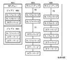
図6は、本発明の第1実施形態における予約ジョブとジョブ処理手順を示した図であり、ウェイトアップ後にプリント処理するキューの先頭ジョブが複数の色モード(印刷モード)のページが混在したジョブである場合に対応する。
【0086】
図6において、601は待ちキューで、図4に示したRAM406に格納されるものであり、ネットワークコントローラ通信部407もしくは操作パネル制御部408のいずれかより入力されたジョブを入力順に蓄積し、順次プリンタ制御部404を介してプリント処理される。
【0087】
この待ちキュー601には、ジョブ1(602),ジョブ2(603)の順番にジョブが予約されている。さらに、ジョブ1(602)は、モノクロページ−モノクロページ−カラーページの順番で構成されている。同様にジョブ2(603)は、モノクロページ−カラーページ−カラーページの順番で構成されている。
【0088】
604はジョブ処理制御で、ウェイトアップ開始後、定着ローラ温度がTkになった時点で、ジョブ1(602)とジョブ2(603)を順次処理する場合に対応する。
【0089】
まず、ジョブ1(602)はモノクロページから開始するので、モノクロページ2ページを出力する。ここで、次ページはカラーであるため、定着ローラの温度が、Tkから、Tcに上昇するまでプリントジョブを中断させる。定着ローラの温度がTcまで上昇すると、ジョブ1(602)のカラーページを印刷し、ジョブ1(602)が完了する。この時、定着ローラの温度はTcに達しているため、ジョブ2(603)は、モノクロページプリント,カラーページプリントのいずれの印刷の際にも、プリントジョブを中断させる必要は無い。
【0090】
次に、605はジョブ処理制御で、ウェイトアップ開始後、定着ローラ温度がカラープリント/モノクロプリントが可能になった時点で、ジョブ1(602)及びジョブ2(603)を処理する場合に対応する。
【0091】
ジョブ1(602)とジョブ2(603)は、共にモノクロページとカラーページから構成されているが、定着ローラ41aの温度がどちらのカラーモードでも定着可能な温度まで達しているため、カラーモードの切り替え時にウェイトすること無く、ジョブ1(602)、ジョブ2(603)を連続印刷処理することができる。
【0092】
このように、ジョブ処理制御604とジョブ処理制御605の2つのジョブ処理制御を比較すると、ジョブ処理制御604において、ウェイトアップ開始からジョブ1(602)終了までに要するウェイト時間の合計は「T5+T7」となる。一方、ジョブ処理制御605において、ウェイトアップ開始からジョブ1(602)終了までに要するウェイト時間の合計は「T1」となる。図5に示したように、T5+T7>T1となり、ジョブ処理制御605の方がジョブ処理制御604より、定着ローラをヒートアップするためのウェイト時間の合計が短くなり、結果としてジョブ処理制御605の方がジョブ1(602)の終了に要する時間も短くなる。
【0093】
また、ジョブ処理制御604では、さらにジョブの途中でのプリント中断によるプリントエンジンの中断が入るため、ジョブ1(602)の終了に要する時間はさらに長くなる。
【0094】
このように、本実施形態の画像形成装置では、ウェイトアップ開始時にキューイングされたジョブ(先頭ジョブ)が、モノクロ/カラー混在の場合には、定着ローラ温度がTc(モノクロ/カラーいずれの印刷モードでも印刷可能な温度)になってからプリントを開始した方が、キュー先頭のジョブを早く処理することが可能になる。
【0095】
以下、図7を参照して、本画像形成装置におけるウェイトアップ後にプリント処理するキューの先頭ジョブがモノクロジョブである場合について述べる。
【0096】
図7は、本発明の第1実施形態における予約ジョブとジョブ処理手順を示した図であり、ウェイトアップ後にプリント処理するキューの先頭ジョブがモノクロジョブである場合に対応する。
【0097】
図において、701は待ちキューで、ジョブ1(702)、ジョブ2(703)の順番にジョブが予約されている。ジョブ1(702)は、モノクロページのみで構成されている。同様にジョブ2(703)は、カラーページ−カラーページ−モノクロページの順番から構成されている。
【0098】
704はジョブ処理制御で、ウェイトアップ開始後、定着ローラ温度がTkになった時点で、ジョブ1(702)とジョブ2(703)を順次処理する場合に対応する。
【0099】
まず、ジョブ1(702)はモノクロページのみの印刷なので、モノクロページ1ページを出力する。次に、ジョブ2(703)を処理するが、ジョブ2(703)は、カラーページを出力する必要があるため、定着ローラ41aの温度が、モノクロプリントのみが可能な定着ローラの温度から、Tcに上昇するまでプリントジョブを中断させる。定着ローラの温度がTcまで上昇すると、ジョブ2(703)のカラーページを2ページ印刷し、続いてモノクロページを1ページ印刷してジョブ2(703)が完了する。
【0100】
次に、705はジョブ処理制御で、ウェイトアップ開始後、定着ローラ温度がTcになった時点で、上記ジョブ1(702)及びジョブ2(703)を処理する場合に対応する。
【0101】
定着ローラの温度はどちらのカラーモードでも定着可能な温度まで達しているため、カラーモードの切り替え時にウェイトすること無く、ジョブ1(702)、ジョブ2(703)を連続印刷処理することができる。
【0102】
このように、ジョブ処理制御704とジョブ処理制御705の2つのジョブ処理制御を比較すると、ジョブ処理制御704におけるウェイトアップ開始からジョブ1(702)終了までに要するウェイト時間は「T5」となる。一方、ジョブ処理制御705におけるウェイトアップ開始からジョブ1(702)終了までに要するウェイト時間は図4に示した「T1」となる。図5に示したように、T5<T1となり、ジョブ処理制御704の方がジョブ処理制御705より、ジョブ1(702)を終了するまでの時間が短くなる。
【0103】
このように、本実施形態の構成を持つ画像形成装置では、ウェイトアップ開始時にキューイングされた先頭のジョブが、モノクロジョブの場合には、定着ローラの温度が、Tk(モノクロの印刷モードのみ印刷可能な温度)になった時点でプリントを開始したほうが、キューの先頭ジョブを早く処理することが可能になる。
【0104】
しかし、ウェイトアップ開始時にキューイングされた先頭の2ジョブが、モノクロジョブ,カラー(又は混在)ジョブの順の場合には、定着ローラの温度が、Tc(モノクロ/カラーの印刷モードのどちらでも印刷可能な温度)になった時点でプリントを開始したほうが、キュー内の複数ジョブを早く処理することが可能になる。
【0105】
即ち、本発明では、複数のプリントジョブをキューイングし、印刷可能状態にあるときは、順次プリントジョブを処理することが可能であり、モノクロ印刷モードと、モノクロ印刷モードよりも定着温度が高いカラー印刷モードを有し、さらに定着ユニットの通電を遮断することによりスタンバイ時の消費電力を低減することが可能な低消費電力モードを有する画像形成装置であって、電源投入時もしくは低電力モード解除時(以後、両タイミングをウエイトアップ開始時と呼ぶ)に、電源投入時に定着器の温度が上昇し、モノクロモードでのプリント可能温度に達した時、先にモノクロモードのジョブのみプリント可能とすることにより、電源投入時からのウォームアップ待機時間を最小限に抑える事を可能にする。同様に、低電力モードからの復帰時にも、モノクロモードのジョブをカラージョブよりも先にプリント可能とすることにより、復帰時間の短縮を実現する。
【0106】
なお、低消費電力モードからの復帰時に、先頭の2つのジョブに同じユーザからのジョブをモノクロジョブ,カラージョブの順で連続的にキューイングしている場合には、定着スタンバイ温度がカラー印刷モードの温度Tcになってから、プリントジョブを開始し、上記以外の場合(低消費電力モードからの復帰時に、先頭の2つのジョブに同じユーザからのジョブをモノクロジョブ,カラージョブの順で連続的にキューイングしていない場合)には、最初にキューイングされたジョブのカラーモードに従った定着スタンバイ温度に達した後に(先頭ジョブがモノクロジョブならTk、カラー(混在)ジョブならTcに達した後に)、プリントジョブを開始するものとする。
【0107】
以下、図8を参照して、本発明の画像形成装置のウェイトアップ後のプリント処理動作について説明する。
【0108】
図8は、本発明の画像形成装置の第1の制御処理手順の一例を示すフローチャートであり、ウェイトアップ後のプリント処理手順に対応する。なお、このフローチャートの処理は、図4に示したCPU401によりROM405又は図示しない記憶媒体に格納されたプログラムに基づいて実行されるものとする。また、S101〜S106は各ステップを示す。
【0109】
まず、ステップS101において、ウェイトアップが開始されると、ステップS102において、プリント処理するキューの先頭ジョブがモノクロジョブであるか否かを判定し、モノクロジョブであると判断された場合は、ステップS103に進み、プリント処理するキューの2番目のジョブが1番目のモノクロジョブと同一ユーザのジョブでかつカラー(又は混在)ジョブ(即ち、先頭2ジョブが同一ユーザのジョブであって、かつモノクロジョブ,カラー(又は混在)ジョブの順)であるか否かを判定し、プリント処理するキューの2番目のジョブが1番目のモノクロジョブと同一ユーザのジョブでかつカラー(又は混在)ジョブ(即ち、先頭2ジョブが同一ユーザのジョブであって、かつモノクロジョブ,カラー(又は混在)ジョブの順)であると判断された場合は、ステップS105において、定着ローラがカラープリント可能な温度であるTcになるまで待機し、Tcになったら、ステップS106において、プリント処理を開始する。
【0110】
一方、ステップS103で、プリント処理するキューの2番目のジョブが1番目のモノクロジョブと同一ユーザのジョブでかつカラー(又は混在)ジョブ(即ち、先頭2ジョブが同一ユーザのジョブであって、かつモノクロジョブ,カラー(又は混在)ジョブの順)でないと判定された場合は、ステップS104に進み、定着ローラがモノクロプリント可能な温度であるTkになるまで待機し、Tkになったら、ステップS106において、プリント処理を開始する。
【0111】
一方、ステップS102で、キューの先頭ジョブがモノクロジョブでない(即ち、キューの先頭ジョブがカラー(又は混在)ジョブ)と判断された場合は、ステップS105に進み、定着ローラがカラープリント可能な温度であるTcになるまで待機し、Tcになったら、ステップS106において、プリント処理を開始する。
【0112】
以上示したように、本発明の画像形成装置は、キューイングされている先頭ジョブのカラーモードによって、ウォームアップ後のプリント開始温度を変えるものである。なお、特に、低消費電力モードからの復帰時に、先頭の2つのジョブに同じユーザからのジョブをモノクロジョブ,カラージョブの順で連続的にキューイングしている場合には、定着スタンバイ温度がカラー印刷モードの温度Tcになってから、プリントジョブを開始し、上記以外の場合(低消費電力モードからの復帰時に、先頭の2つのジョブに同じユーザからのジョブをモノクロジョブ,カラージョブの順で連続的にキューイングしていない場合)には、最初にキューイングされたジョブのカラーモードに従った定着スタンバイ温度に達した後に(先頭ジョブがモノクロジョブならTk、カラー(混在)ジョブならTcに達した後に)、プリントジョブを開始することにより、低電力モード等から復帰後の最初のユーザのジョブが処理されるために要する時間を短縮することができる。特に、プリントジョブが入力される頻度が低く頻繁に低電力モードから復帰するような環境にある画像形成装置に対しては、特に有効となる。
【0113】
〔第2実施形態〕
図9は、本発明の第2実施形態を示す画像形成装置を適用可能な画像形成システムを示す図であり、図1と同一のものには同一の符号を付してある。
【0114】
図において、805はFAXコントローラである。複写機103は、マルチファンクション複写機であり、コピー,ネットワークプリントの他に、FAXを送受信することが出来る。FAXコントローラ805は、モデム806を介して公衆電話回線に接続されている。公衆電話回線を介して受信したFAX文書は、FAXコントローラ805内でFAXプロトコルから画像データへと変換され、FAXコントローラ805内に有するメモリに蓄積される。
【0115】
FAXコントローラ805は、複写機103に対してFAXジョブのプリント要求を送信し、複写機103は、FAXコントローラ805からのプリント要求を受信すると、FAXジョブをプリント待ちキューに格納し、待ちキュー内のジョブが処理されて、FAXジョブのプリントが可能になった時、FAXデータをプリント処理する。また、FAXデータはモノクロデータである。
【0116】
また、複写機103は、FAXジョブもしくはネットワークプリントジョブを受信した時、もしくは操作パネルからコピージョブの設定が入力された時に低電力モードから解除される。
【0117】
なお、本実施形態における複写機103の概略,操作パネル表示,定着ローラの温度遷移特性は、上記第1実施形態において図2に示した複写機103の断面図,図3に示した操作パネル表示,図5に示した定着ローラの温度遷移特性と同様であるため省略する。
【0118】
図10は、図9に示した複写機103の制御ユニットの構成を示すブロック図であり、図4と同一のものには同一の符号を付してある。
【0119】
図において、908はFAXボード通信部で、FAXボード(FAXコントローラ805)と通信することにより、FAX受信ジョブの有無、FAXデータの送受信を行うことができる。
【0120】
なお、図10に示したCPU401は、定着ユニット40に設けられた図示しない温度センサによる定着ユニット40内の定着ローラの温度計測結果に従って、定着ローラの温度がTkに到達した後にTcを上回った(到達した)ことをRAM406に記憶させ、定着ローラの温度がTcを下回った場合、RAM406の記憶内容(定着ローラの温度がTkに到達した後にTcを上回ったこと)を解除するものであり、この記憶内容に基づいて、CPU401は、後述するジョブの開始,中断等を制御する。
【0121】
このように、複写機103が、コピー、プリント、FAX機能を持つマルチファンクション複写機である場合、キューイングされているジョブのカラーモードの関係から、電源投入後もしくは低電力モード解除後に、モノクロジョブが優先して出力されるようにジョブの処理手順をコントロールすることにより、使用頻度が比較的低く、低電力モードからの解除が頻繁に行われるような使用状況のプリンタで、なおかつ比較的モノクロジョブが多く処理される時には、プリント処理が完了するまでの待ち時間を大幅に短縮することができる。
【0122】
以下、図11を参照して、本発明の第2実施形態を示す画像形成装置における予約ジョブとジョブ処理手順について説明する。
【0123】
図11は、本発明の第2実施形態における予約ジョブとジョブ処理手順を示した図であり、ウェイトアップ後にプリント処理するキューの先頭ジョブがFAXジョブ(ファクシミリ受信データのプリントジョブ)である場合に対応する。
【0124】
図において、1001は待ちキューで、図9に示したRAM406に格納されており、FAXボード通信部908もしくはネットワークコントローラ通信部407もしくは操作パネル制御部409のいずれかより入力されたジョブを入力順に管理し、順次プリンタ制御部404を介してプリント処理する。
【0125】
待ちキュー1001には、ジョブ1(1002)、ジョブ2(1003)の順番にジョブが予約されている。ジョブ1002は、FAXジョブであり、ジョブ1003は、カラーページ−カラーページの順番から構成されている。
【0126】
1004はジョブ処理制御で、待ちキューにFAXジョブがあることが分かっているため、第1のジョブはモノクロジョブとなる。従って、ウェイトアップ開始後、定着ローラ温度がTkになった時点で、FAXジョブ1002をプリント処理する。ここで、次ジョブ1003は、カラージョブであるため、定着ローラの温度が、Tkから、Tcに上昇するまでプリントジョブを中断させる。定着ローラの温度がTcまで上昇すると、ジョブ1003を印刷する。
【0127】
このように、FAXジョブが待ちキューの先頭にあるという条件であれば、定着ヒータの温度がTkでプリントを開始することにより、ウェイトアップ開始後から、先頭ジョブ出力に要する時間を短縮することが可能になる。 また、本実施形態では、待ちキューにFAXジョブがあることを条件としたが、例えばFAXが受信中であっても、低電力モードが解除された場合には、FAXの受信が終了した時に、モノクロプリント可能な温度に達していれば、定着ヒータの温度がTkで、FAXジョブをプリント開始することも可能である。
【0128】
以下、図12を参照して、本発明の第2実施形態を示す画像形成装置のウェイトアップ後のプリント処理動作について説明する。
【0129】
図12は、本発明の画像形成装置の第2の制御処理手順の一例を示すフローチャートであり、ウェイトアップ後のプリント処理手順に対応する。なお、このフローチャートの処理は、図10に示したCPU401によりROM405又は図示しない記憶媒体に格納されたプログラムに基づいて実行されるものとする。また、S201〜S207は各ステップを示す。
【0130】
まず、ステップS201において、ウェイトアップが開始されると、ステップS202において、プリント処理するキューの先頭ジョブがFAX(又はモノクロ)ジョブであるか否かを判定し、キューの先頭ジョブがFAX(モノクロ)ジョブであると判断された場合は、ステップS203において、定着ローラがモノクロプリントのみ可能な温度であるTkになるまで待機し、Tkになったら、ステップS204において、FAX(モノクロ)プリント処理を行う。
【0131】
FAX(モノクロ)プリント処理が終了すると、ステップS205において、次のジョブがモノクロジョブか否かを判定し、モノクロジョブであると判断された場合は、ステップS204に戻り、FAXジョブやモノクロジョブのプリント処理を行う。
【0132】
一方、ステップS205で、次のジョブがモノクロジョブでないと判断された場合は、ステップS206において、定着ローラがカラープリント可能な温度であるTcになるまで処理を中断して待機し、Tcになったら、ステップS207において、カラー(混在)プリント処理を開始する。
【0133】
一方、ステップS202で、キューの先頭ジョブがFAX(モノクロ)ジョブでないと判断された場合は、ステップS206に進み、定着ローラがカラープリント可能な温度であるTcになるまで待機し、Tcになったら、ステップS207において、カラー(混在)プリント処理を開始する。
【0134】
なお、ステップS205では次のジョブがモノクロジョブでない場合はすぐにプリント処理を中断させ、定着ローラの温度がカラープリント可能な温度Tcになってからプリント処理を開始する場合について説明したが、ステップS205で、次のジョブがモノクロジョブでなくても混在ジョブで先頭がモノクロページの場合には、先頭から連続するモノクロページのみを先にプリントして、その後ステップS206に進み、定着ローラの温度がTcになるまでプリントを中断するように構成してもよい。
【0135】
以上説明したように、ネットワークプリンタ102が、コピー、プリント、FAX機能を持つマルチファンクション複写機である場合、キューイングされているジョブのカラーモードの関係から、電源投入後もしくは低電力モード解除後に、定着ローラの温度が、モノクロジョブがプリント可能な温度になると直ちに出力開始することにより、使用頻度が比較的低く、低電力モードからの解除が頻繁に行われるような使用状況のプリンタで、なおかつ比較的モノクロジョブが多く処理される時には、プリント処理が完了するまでの待ち時間を大幅に短縮することが出来る。
【0136】
以上より、本発明の画像形成装置は、低消費電力モードからの復帰時に、キューイングされている先頭ジョブのカラーモードによって、ウォームアップ後のプリント開始温度を変えるものである(先頭ジョブがモノクロジョブの場合はモノクロ印刷モードの温度Tk,先頭ジョブがカラージョブ(又は混在ジョブ)の場合はカラー印刷モードの温度Tcとする)。なお、先頭のジョブがモノクロジョブであっても、先頭の2つのジョブに同じユーザからのジョブをモノクロジョブ,カラージョブの順で連続的にキューイングしている場合には、定着スタンバイ温度がカラー印刷モードの温度Tcになってから、プリントジョブを開始し、上記以外の場合(低消費電力モードからの復帰時に、先頭の2つのジョブに同じユーザからのジョブをモノクロジョブ,カラージョブの順で連続的にキューイングしていない場合)には、最初にキューイングされたジョブのカラーモードに従った定着スタンバイ温度に達した後に(先頭ジョブがモノクロジョブならTk、カラー(混在)ジョブならTcに達した後に)、プリントジョブを開始する。
【0137】
これにより、低電力モード等から復帰後の最初のジョブ(特に先頭の2つのジョブに同じユーザからのジョブをモノクロジョブ,カラージョブの順である場合は、最初のユーザのジョブ)が処理されるために要する時間を短縮することができる。また、特に、プリントジョブが入力される頻度が低く頻繁に低電力モードから復帰するような環境にある画像形成装置に対しては、特に有効となる。
【0138】
さらに、特にプリントジョブが入力される頻度が低く、低消費電力モードから頻繁にFAX印刷のために復帰するような環境に在る画像形成装置に対しても特に有効となる。
【0139】
従って、使用頻度が比較的低く、低電力モードからの解除が頻繁に行われるような使用状況のプリンタで、なおかつ比較的モノクロジョブが多く処理される時には、プリント処理が完了するまでの待ち時間を大幅に短縮することが出来る。
【0140】
なお、上記各実施形態では、プリンタ部(プリンタエンジン)がレーザビーム方式である場合を例にして説明したが、レーザビーム方式以外の電子写真方式(例えばLED方式)であっても本発明は適用可能である。
【0141】
また、上記各実施形態を合わせた構成も本発明に含まれるものである。
【0142】
以下、図13に示すメモリマップを参照して本発明に係る画像形成装置で読み出し可能なデータ処理プログラムの構成について説明する。
【0143】
図13は、本発明に係る画像形成装置で読み出し可能な各種データ処理プログラムを格納する記憶媒体のメモリマップを説明する図である。
【0144】
なお、特に図示しないが、記憶媒体に記憶されるプログラム群を管理する情報、例えばバージョン情報,作成者等も記憶され、かつ、プログラム読み出し側のOS等に依存する情報、例えばプログラムを識別表示するアイコン等も記憶される場合もある。
【0145】
さらに、各種プログラムに従属するデータも上記ディレクトリに管理されている。また、インストールするプログラムやデータが圧縮されている場合に、解凍するプログラム等も記憶される場合もある。
【0146】
本実施形態における図8,図12に示す機能が外部からインストールされるプログラムによって、ホストコンピュータにより遂行されていてもよい。そして、その場合、CD−ROMやフラッシュメモリやFD等の記憶媒体により、あるいはネットワークを介して外部の記憶媒体から、プログラムを含む情報群を出力装置に供給される場合でも本発明は適用されるものである。
【0147】
以上のように、前述した実施形態の機能を実現するソフトウエアのプログラムコードを記録した記憶媒体を、システムあるいは装置に供給し、そのシステムあるいは装置のコンピュータ(またはCPUやMPU)が記憶媒体に格納されたプログラムコードを読出し実行することによっても、本発明の目的が達成されることは言うまでもない。
【0148】
この場合、記憶媒体から読み出されたプログラムコード自体が本発明の新規な機能を実現することになり、そのプログラムコードを記憶した記憶媒体は本発明を構成することになる。
【0149】
プログラムコードを供給するための記憶媒体としては、例えば、フロッピー(登録商標)ディスク,ハードディスク,光ディスク,光磁気ディスク,CD−ROM,CD−R,DVD−ROM,磁気テープ,不揮発性のメモリカード,ROM,EEPROM,シリコンディスク等を用いることができる。
【0150】
また、コンピュータが読み出したプログラムコードを実行することにより、前述した実施形態の機能が実現されるだけでなく、そのプログラムコードの指示に基づき、コンピュータ上で稼働しているOS(オペレーティングシステム)等が実際の処理の一部または全部を行い、その処理によって前述した実施形態の機能が実現される場合も含まれることは言うまでもない。
【0151】
さらに、記憶媒体から読み出されたプログラムコードが、コンピュータに挿入された機能拡張ボードやコンピュータに接続された機能拡張ユニットに備わるメモリに書き込まれた後、そのプログラムコードの指示に基づき、その機能拡張ボードや機能拡張ユニットに備わるCPU等が実際の処理の一部または全部を行い、その処理によって前述した実施形態の機能が実現される場合も含まれることは言うまでもない。
【0152】
また、本発明は、複数の機器から構成されるシステムに適用しても、1つの機器からなる装置に適用してもよい。また、本発明は、システムあるいは装置にプログラムを供給することによって達成される場合にも適応できることは言うまでもない。この場合、本発明を達成するためのソフトウエアによって表されるプログラムを格納した記憶媒体を該システムあるいは装置に読み出すことによって、そのシステムあるいは装置が、本発明の効果を享受することが可能となる。
【0153】
さらに、本発明を達成するためのソフトウエアによって表されるプログラムをネットワーク上のデータベースから通信プログラムによりダウンロードして読み出すことによって、そのシステムあるいは装置が、本発明の効果を享受することが可能となる。
【0154】
【発明の効果】
以上説明したように、本発明によれば、定着ユニットを画像の種類に応じた所定温度にするために要するトータルな時間が短くなり、結果として画像形成ジョブの終了までに要する時間も短くなる。
また、本発明によれば、低電力モード等から復帰後の最初のジョブが処理されるために要する時間を短縮することができる。特に、プリントジョブが入力される頻度が低く頻繁に低電力モードに移行してしまい、頻繁に低電力モードから復帰するような画像形成環境において有効である。また、プリントジョブが入力される頻度が低く頻繁に低電力モードに移行してしまい、低消費電力モードから頻繁にFAX印刷のために復帰するような画像形成環境においても有効である。
【0155】
従って、使用頻度が比較的低く、低電力モードからの解除が頻繁に行われる様な使用状況で、なおかつ比較的モノクロジョブが多く処理される画像形成環境において、プリント処理が完了するまでの待ち時間を大幅に短縮することができる等の効果を奏する。
また、本発明によれば、画像形成ジョブにカラーページが含まれなくても、その後続の画像形成ジョブにカラーページが含まれている場合は、定着ユニットの温度を第2の温度に制御するので、定着ユニットを画像の種類に応じた所定温度にするために要するトータル時間が短くなり、結果として画像形成ジョブの終了までに要する時間も短くなる。
【図面の簡単な説明】
【図1】本発明の第1実施形態を示す画像形成装置を適用可能な画像形成システムを示す図である。
【図2】図1に示した複写機の構成を示す断面図である。
【図3】図2に示した複写機の操作パネルの概観を示す平面図である。
【図4】図1に示した複写機の制御ユニットの構成を示すブロック図である。
【図5】本発明の第1実施形態における定着ローラの温度遷移を表した特性図である。
【図6】本発明の第1実施形態における予約ジョブとジョブ処理手順を示す図である。
【図7】本発明の第1実施形態における予約ジョブとジョブ処理手順を示す図である。
【図8】本発明の画像形成装置の第1の制御処理手順の一例を示すフローチャートである。
【図9】本発明の第2実施形態を示す画像形成装置を適用可能な画像形成システムを示す図である。
【図10】図9に示した複写機の制御ユニットの構成を示すブロック図である。
【図11】本発明の第2実施形態における予約ジョブとジョブ処理手順を示す図である。
【図12】本発明の画像形成装置の第2の制御処理手順の一例を示すフローチャートである。
【図13】本発明に係る画像形成装置で読み出し可能な各種データ処理プログラムを格納する記憶媒体のメモリマップを説明する図である。
【符号の説明】
401 CPU
402 イメージリーダ制御部
403 画像信号制御部
404 プリンタ制御部
405 ROM
406 RAM
407 ネットワークコントローラ通信部
408 操作パネル制御部[0001]
BACKGROUND OF THE INVENTION
The present invention relates to an image forming apparatus adopting an electrostatic recording system, an electrophotographic recording system, or the like, a control method of the image forming apparatus, a program, and a storage medium.
[0002]
[Prior art]
Hereinafter, fixing device control of this type of image forming apparatus will be described.
[0003]
In a color image forming apparatus that employs an electrostatic recording system or an electrophotographic recording system such as a conventional copying machine or printer, when the power is turned on, the fixing heater is energized until the temperature reaches the print startable temperature. When the temperature of the fixing device reaches the printable temperature, the printing operation becomes possible, and the energization to the fixing heater is stopped. When the temperature of the fixing device falls below the printable temperature again, the energization is performed again.
[0004]
In addition, there has been proposed an image forming apparatus having a low power mode that reduces power consumption during standby by continuously interrupting energization of the fixing heater when no print job is input for a certain period of time.
[0005]
The image forming apparatus in the low power mode state restarts energization to the fixing heater when a print job is input again, and starts a printing operation when detecting that the fixing temperature has risen to a print start possible temperature. It is configured.
[0006]
[Problems to be solved by the invention]
Generally, image forming apparatuses that are shared by many people in offices and the like are often set to shift to a low power mode by a timer. If the frequency of using the image forming apparatus is low, a print job is input. In many cases, the printing is started after the fixing device is heated from the power saving state to the standby state each time.
[0007]
In such a case, if the recovery time of the fixing device is long, not only does the waiting time until printing increase and the user's work efficiency does not increase, but also the energization time of the fixing device becomes long. There has been a problem that the power consumption required to recover is increased.
[0008]
The present invention has been made to solve the above problems, and the object of the present invention is to reduce the time required for processing the first job after returning from the low power mode or the like, In particular, an image forming apparatus that is effective in an image forming environment in which a print job is input less frequently and frequently shifts to the low power mode and frequently returns from the low power mode.PlaceIs to provide.
[0015]
[Means for Solving the Problems]
Main departureTomorrowA fixing unit for thermally fixing the sheet to which the developer has been transferred, a temperature for the fixing unit, a first temperature for fixing the developer representing a monochrome image on the sheet, and a developer representing a color image. Control means for controlling to any one of the second temperatures for fixing toStorage means capable of queuing a plurality of image forming jobs including job print mode and job user information;The control means should process when power is turned on or when the low power consumption mode is released.The first and subsequent jobs queued in the storage means are jobs from the same user and are sequentially queued in the order of the first job that does not include a color page and the subsequent job that includes a color page. In this state, the temperature of the fixing unit that starts printing of the first job is determined as the second temperature, and the plurality of jobs are jobs from different users and include color pages. In the state where the first job that has not been printed and the subsequent job that includes color pages are successively queued, the temperature of the fixing unit that starts printing the first job is determined as the first temperature.It is characterized by doing.
[0026]
DETAILED DESCRIPTION OF THE INVENTION
[First Embodiment]
FIG. 1 is a diagram showing an image forming system to which the image forming apparatus showing the first embodiment of the present invention can be applied.
[0027]
In the figure,
[0028]
[0029]
If the document created on the computer is a monochrome file such as a document, the
[0030]
As described above, the copier 103 (network controller 104) is connected to the
[0031]
In FIG. 1, it is described as if there is a single host computer on the
[0032]
FIG. 2 is a sectional view showing the configuration of the
[0033]
In the drawing, reference numeral 1R denotes an image reader, which can read image data from a document placed on a document table.
[0034]
An image output unit 1P is roughly divided into an image forming unit 10 (four stations a, b, c, and d are arranged in parallel, and the configuration is the same), a
[0035]
Hereinafter, each unit will be described in detail.
[0036]
The
[0037]
[0038]
Hereinafter, an image forming process of the
[0039]
First, in the
[0040]
On the downstream side of the image transfer regions TRa, TRb, TRc, TRd where the visualized visible image is transferred to the intermediate transfer member, the photosensitive drums 11a, 11a, 15d are not transferred to the transfer material by the
[0041]
Next, the
[0042]
Next, in the
[0043]
Among these, a primary transfer plane A is formed between the driving
[0044]
Further, in the primary transfer regions TRa, TRb, TRc, TRd where the
[0045]
A
[0046]
A
[0047]
Next, the fixing
[0048]
Next, the control unit described above includes a control board 70 for controlling the operation of the mechanism in each unit, a motor drive board (not shown), and the like.
[0049]
Hereinafter, the image forming operation will be described.
[0050]
When an image forming operation start signal is issued, first, the transfer material P is sent out one by one from the
[0051]
On the other hand, when an image forming operation start signal is issued, the
[0052]
Thereafter, when the recording material P enters the secondary transfer region Te and contacts the
[0053]
Thereafter, the recording material P is accurately guided to the fixing roller nip portion by the
[0054]
Next, control of the fixing
[0055]
When the power is turned on, the fixing heater (heat source such as a halogen heater) is energized until the fixing
[0056]
Further, the
[0057]
When a print job is input again in the low power mode, the energization of the fixing heater is resumed, and when it is detected that the fixing temperature has risen to a predetermined temperature, the printing operation is started.
[0058]
The
[0059]
When the data input from the
[0060]
This print mode can be automatically determined by the image forming apparatus by determining the data type, or can be transmitted by designating a color mode (print mode) from the
[0061]
The operation panel of the copying
[0062]
FIG. 3 is a plan view showing an overview of the operation panel of the copying
[0063]
In the figure,
[0064]
[0065]
Next,
[0066]
[0067]
[0068]
[0069]
[0070]
Status displays 311, 315, 316, and 317 displayed on the operation
[0071]
FIG. 4 is a block diagram showing the configuration of the control unit of the copying
[0072]
In the figure,
[0073]
An image
[0074]
[0075]
As shown in FIG. 2, in a full color mode, an electrophotographic color image forming apparatus that transfers toner of four colors of yellow (Y), magenta (M), cyan (C), and black (K) to a transfer sheet is used. Since the amount of toner transferred onto the paper is greatly different between the monochrome mode and the color mode, the amount of heat that the fixing
[0076]
So, when the power is turned on or the low power mode is released (hereinafter both timings are called wait start), when the temperature of the fixing unit rises and reaches the printable temperature in monochrome mode, By enabling printing of only this job, it is possible to minimize the warm-up waiting time after power-on or when returning from the low power mode.
[0077]
FIG. 5 is a characteristic diagram showing a temperature transition of the fixing
[0078]
In the figure,
[0079]
[0080]
First, in the
[0081]
Next, also in the
[0082]
Here, when printing of a monochrome job is started, the fixing roller temperature is lower than the monochrome standby temperature because the fixing heater is deprived of heat by fixing the paper during the printing time T6. When printing is completed, the temperature rises to Tc after time T7. If the temperature exceeds Tc, the heater is turned off, and if it falls below Tc, the heater is turned on. When printing starts during time T8, the fixing heater is deprived of heat by fixing the paper during the printing time T9, so the fixing roller temperature becomes lower than the control temperature Tc. When printing is completed, printing can be accepted and the fixing roller temperature is controlled to be kept at Tc.
[0083]
The
[0084]
Hereinafter, a reserved job and a job processing procedure in the image forming apparatus according to the first embodiment of the present invention will be described with reference to FIGS.
[0085]
FIG. 6 is a diagram showing a reserved job and a job processing procedure according to the first embodiment of the present invention. A job in which the first job of the queue to be printed after waiting up is a mixture of pages of a plurality of color modes (print modes). Corresponds to the case.
[0086]
In FIG. 6,
[0087]
In this waiting
[0088]
[0089]
First, since job 1 (602) starts from a monochrome page, two monochrome pages are output. Here, since the next page is color, the print job is suspended until the temperature of the fixing roller rises from Tk to Tc. When the temperature of the fixing roller rises to Tc, the color page of job 1 (602) is printed, and job 1 (602) is completed. At this time, since the temperature of the fixing roller has reached Tc, it is not necessary for job 2 (603) to interrupt the print job in both monochrome page printing and color page printing.
[0090]
Next,
[0091]
Job 1 (602) and job 2 (603) are both composed of monochrome pages and color pages. However, since the temperature of the fixing
[0092]
In this way, when comparing the two job processing controls of the
[0093]
Further, in the
[0094]
As described above, in the image forming apparatus according to the present exemplary embodiment, when the job (first job) queued at the start of wait-up is monochrome / color mixed, the fixing roller temperature is Tc (monochrome / color printing mode). However, if the print is started after the printable temperature is reached, the job at the head of the queue can be processed faster.
[0095]
Hereinafter, with reference to FIG. 7, a case will be described in which the first job in the queue to be printed after waiting up in the image forming apparatus is a monochrome job.
[0096]
FIG. 7 is a diagram showing a reserved job and a job processing procedure according to the first embodiment of the present invention, and corresponds to a case where the first job in the queue to be printed after waiting is a monochrome job.
[0097]
In the figure,
[0098]
[0099]
First, since job 1 (702) prints only monochrome pages, one monochrome page is output. Next, job 2 (703) is processed. Since job 2 (703) needs to output a color page, the temperature of the fixing
[0100]
[0101]
Since the temperature of the fixing roller has reached a temperature at which fixing can be performed in either color mode, job 1 (702) and job 2 (703) can be continuously printed without waiting when the color mode is switched.
[0102]
As described above, when the two job processing controls of the
[0103]
As described above, in the image forming apparatus having the configuration of the present embodiment, when the head job queued at the start of the wait-up is a monochrome job, the temperature of the fixing roller is Tk (printing only in the monochrome print mode). It is possible to process the first job in the queue earlier when printing is started when the temperature reaches a possible temperature.
[0104]
However, if the first two jobs queued at the start of wait up are monochrome jobs and color (or mixed) jobs in this order, the fixing roller temperature is printed in either Tc (monochrome / color printing mode). It is possible to process a plurality of jobs in the queue faster by starting printing when the temperature reaches a possible temperature.
[0105]
In other words, according to the present invention, when a plurality of print jobs are queued and are in a printable state, it is possible to sequentially process the print jobs, and the monochrome print mode and a color having a higher fixing temperature than the monochrome print mode. An image forming apparatus having a low power consumption mode that has a print mode and can reduce power consumption during standby by shutting off the energization of the fixing unit, when the power is turned on or the low power mode is released When the temperature of the fuser rises when the power is turned on and reaches the printable temperature in the monochrome mode (hereinafter, both timings are referred to as the start of weight-up), only monochrome mode jobs can be printed first. This makes it possible to minimize the warm-up waiting time after power-on. Similarly, when returning from the low power mode, the monochrome mode job can be printed before the color job, thereby reducing the return time.
[0106]
When returning from the low power consumption mode, if the jobs from the same user are continuously queued in the order of monochrome jobs and color jobs in the first two jobs, the fixing standby temperature is the color print mode. The print job is started after the temperature Tc is reached, and in other cases (when returning from the low power consumption mode, the jobs from the same user are continuously printed in the order of monochrome jobs and color jobs in the first two jobs. If the first job is a monochrome job, it reaches Tk, and if it is a color (mixed) job, Tc is reached after reaching the fixing standby temperature according to the color mode of the first queued job. Later, the print job shall be started.
[0107]
Hereinafter, with reference to FIG. 8, the print processing operation after the wait of the image forming apparatus of the present invention will be described.
[0108]
FIG. 8 is a flowchart showing an example of the first control processing procedure of the image forming apparatus according to the present invention, and corresponds to the print processing procedure after waiting up. Note that the processing in this flowchart is executed by the
[0109]
First, when wait-up is started in step S101, it is determined in step S102 whether the first job in the queue to be printed is a monochrome job. If it is determined that the job is a monochrome job, step S103 is performed. The second job in the queue to be printed is the same user job as the first monochrome job and the color (or mixed) job (that is, the first two jobs are the same user job and the monochrome job, The second job in the queue for print processing is a job of the same user as the first monochrome job and a color (or mixed) job (that is, the first job). Two jobs are jobs of the same user, monochrome jobs, color (or mixed) jobs If it is determined that), in step S105, the fixing roller waits until Tc is a color printable temperature, when turned Tc, in step S106, it starts the printing process.
[0110]
On the other hand, in step S103, the second job in the queue for print processing is a job of the same user as the first monochrome job and a color (or mixed) job (that is, the first two jobs are jobs of the same user, and If it is determined that the order is not monochrome job and color (or mixed) job), the process proceeds to step S104 and waits until the temperature at which the fixing roller can perform monochrome printing reaches Tk. The print process is started.
[0111]
On the other hand, if it is determined in step S102 that the first job in the queue is not a monochrome job (that is, the first job in the queue is a color (or mixed) job), the process proceeds to step S105 and the fixing roller is at a temperature at which color printing is possible. The process waits until a certain Tc is reached. When the Tc is reached, the printing process is started in step S106.
[0112]
As described above, the image forming apparatus of the present invention changes the print start temperature after warm-up according to the color mode of the queued first job. In particular, when returning from the low power consumption mode, if the jobs from the same user are continuously queued in the order of monochrome jobs and color jobs in the first two jobs, the fixing standby temperature is set to color. When the print mode temperature Tc is reached, the print job is started. In cases other than the above (when returning from the low power consumption mode, jobs from the same user are assigned to the first two jobs in the order of monochrome job and color job) If the job is not continuously queued), after reaching the fixing standby temperature according to the color mode of the first queued job (Tk if the first job is a monochrome job, Tc if it is a color (mixed) job) The first user's job after returning from low power mode etc. is processed by starting the print job It is possible to shorten the time required in order. This is particularly effective for an image forming apparatus that is in an environment in which a print job is input less frequently and frequently returns from the low power mode.
[0113]
[Second Embodiment]
FIG. 9 is a diagram illustrating an image forming system to which the image forming apparatus according to the second embodiment of the present invention can be applied. The same components as those in FIG. 1 are denoted by the same reference numerals.
[0114]
In the figure,
[0115]
The
[0116]
The
[0117]
The outline of the copying
[0118]
10 is a block diagram showing the configuration of the control unit of the copying
[0119]
In the figure,
[0120]
The
[0121]
As described above, when the
[0122]
Hereinafter, a reserved job and a job processing procedure in the image forming apparatus according to the second embodiment of the present invention will be described with reference to FIG.
[0123]
FIG. 11 is a diagram showing a reserved job and a job processing procedure according to the second embodiment of the present invention. In the case where the first job in the queue to be printed after waiting is a FAX job (facsimile received data print job). Correspond.
[0124]
In the figure,
[0125]
In the
[0126]
[0127]
As described above, under the condition that the FAX job is at the head of the waiting queue, the time required for the head job output can be shortened after the start of the wait-up by starting printing at the temperature of the fixing heater Tk. It becomes possible. Further, in this embodiment, it is a condition that there is a FAX job in the waiting queue. However, for example, even when a FAX is being received, when the low power mode is canceled, when the FAX reception ends, If the temperature reaches a temperature at which monochrome printing is possible, it is possible to start printing a FAX job at the temperature of the fixing heater Tk.
[0128]
Hereinafter, with reference to FIG. 12, the print processing operation after the wait of the image forming apparatus showing the second embodiment of the present invention will be described.
[0129]
FIG. 12 is a flowchart showing an example of the second control processing procedure of the image forming apparatus according to the present invention, and corresponds to the print processing procedure after waiting up. Note that the processing in this flowchart is executed by the
[0130]
First, when wait-up is started in step S201, it is determined in step S202 whether or not the first job in the queue to be printed is a FAX (or monochrome) job, and the first job in the queue is FAX (monochrome). When it is determined that the job is a job, in step S203, the process waits until the fixing roller reaches a temperature Tk that allows only monochrome printing. When the temperature reaches Tk, a FAX (monochrome) print process is performed in step S204.
[0131]
When the FAX (monochrome) print process is completed, it is determined in step S205 whether or not the next job is a monochrome job. If it is determined that the job is a monochrome job, the process returns to step S204 to print a FAX job or monochrome job. Process.
[0132]
On the other hand, if it is determined in step S205 that the next job is not a monochrome job, in step S206, the process is suspended and waits until the temperature at which the fixing roller can perform color printing reaches Tc. In step S207, color (mixed) print processing is started.
[0133]
On the other hand, if it is determined in step S202 that the first job in the queue is not a FAX (monochrome) job, the process proceeds to step S206, and waits until the fixing roller reaches a temperature Tc at which color printing can be performed. In step S207, color (mixed) print processing is started.
[0134]
In step S205, when the next job is not a monochrome job, the printing process is immediately interrupted, and the printing process is started after the temperature of the fixing roller reaches the temperature Tc at which color printing can be performed. If the next job is not a monochrome job but is a mixed job and starts with a monochrome page, only the monochrome page continuous from the beginning is printed first, and then the process proceeds to step S206, where the temperature of the fixing roller is Tc. You may comprise so that printing may be interrupted until it becomes.
[0135]
As described above, when the
[0136]
As described above, the image forming apparatus of the present invention changes the print start temperature after warm-up according to the color mode of the queued first job when returning from the low power consumption mode (the first job is a monochrome job). Is the temperature Tk in the monochrome print mode, and the color print mode temperature Tc if the top job is a color job (or mixed job). Even if the first job is a monochrome job, if the jobs from the same user are continuously queued in the order of the monochrome job and the color job in the first two jobs, the fixing standby temperature is the color job. When the print mode temperature Tc is reached, the print job is started. In cases other than the above (when returning from the low power consumption mode, jobs from the same user are assigned to the first two jobs in the order of monochrome job and color job) If the job is not continuously queued), after reaching the fixing standby temperature according to the color mode of the first queued job (Tk if the first job is a monochrome job, Tc if it is a color (mixed) job) Start the print job.
[0137]
As a result, the first job after returning from the low power mode or the like (especially, the job from the same user as the first two jobs in the order of the monochrome job and the color job for the first two jobs) is processed. Therefore, the time required for this can be shortened. In particular, this is particularly effective for an image forming apparatus that is in an environment in which a print job is input less frequently and frequently returns from the low power mode.
[0138]
Further, the present invention is particularly effective for an image forming apparatus that is in an environment where the frequency of inputting a print job is low and the printer frequently returns from the low power consumption mode for FAX printing.
[0139]
Therefore, when the printer is used in a state where the usage frequency is relatively low and the release from the low power mode is frequently performed, and a relatively large number of monochrome jobs are processed, the waiting time until the print processing is completed is increased. It can be greatly shortened.
[0140]
In each of the above-described embodiments, the case where the printer unit (printer engine) is a laser beam method has been described as an example. However, the present invention can be applied to an electrophotographic method (for example, an LED method) other than the laser beam method. Is possible.
[0141]
Moreover, the structure which combined said each embodiment is also contained in this invention.
[0142]
The configuration of a data processing program that can be read by the image forming apparatus according to the present invention will be described below with reference to the memory map shown in FIG.
[0143]
FIG. 13 is a diagram illustrating a memory map of a storage medium that stores various data processing programs that can be read by the image forming apparatus according to the present invention.
[0144]
Although not particularly illustrated, information for managing a program group stored in the storage medium, for example, version information, creator, etc. is also stored, and information depending on the OS on the program reading side, for example, a program is identified and displayed. Icons may also be stored.
[0145]
Further, data depending on various programs is also managed in the directory. In addition, when a program or data to be installed is compressed, a program to be decompressed may be stored.
[0146]
The functions shown in FIGS. 8 and 12 in this embodiment may be performed by a host computer by a program installed from the outside. In this case, the present invention is applied even when an information group including a program is supplied to the output device from a storage medium such as a CD-ROM, a flash memory, or an FD, or from an external storage medium via a network. Is.
[0147]
As described above, a storage medium storing software program codes for realizing the functions of the above-described embodiments is supplied to the system or apparatus, and the computer (or CPU or MPU) of the system or apparatus stores the storage medium in the storage medium. It goes without saying that the object of the present invention can also be achieved by reading and executing the programmed program code.
[0148]
In this case, the program code itself read from the storage medium realizes the novel function of the present invention, and the storage medium storing the program code constitutes the present invention.
[0149]
As a storage medium for supplying the program code, for example, a floppy (registered trademark) disk, a hard disk, an optical disk, a magneto-optical disk, a CD-ROM, a CD-R, a DVD-ROM, a magnetic tape, a nonvolatile memory card, ROM, EEPROM, silicon disk, etc. can be used.
[0150]
Further, by executing the program code read by the computer, not only the functions of the above-described embodiments are realized, but also an OS (operating system) or the like running on the computer based on the instruction of the program code. It goes without saying that a case where the function of the above-described embodiment is realized by performing part or all of the actual processing and the processing is included.
[0151]
Further, after the program code read from the storage medium is written to a memory provided in a function expansion board inserted into the computer or a function expansion unit connected to the computer, the function expansion is performed based on the instruction of the program code. It goes without saying that the case where the CPU or the like provided in the board or the function expansion unit performs part or all of the actual processing and the functions of the above-described embodiments are realized by the processing.
[0152]
Further, the present invention may be applied to a system composed of a plurality of devices or an apparatus composed of a single device. Needless to say, the present invention can be applied to a case where the present invention is achieved by supplying a program to a system or apparatus. In this case, by reading the storage medium storing the program represented by the software for achieving the present invention into the system or apparatus, the system or apparatus can enjoy the effects of the present invention. .
[0153]
Furthermore, by downloading and reading a program represented by software for achieving the present invention from a database on a network by a communication program, the system or apparatus can enjoy the effects of the present invention. .
[0154]
【The invention's effect】
As explained above, according to the present invention,, ConstantThe total time required to bring the arrival unit to a predetermined temperature corresponding to the type of image is shortened, and as a result, the time required to complete the image forming job is also shortened.
Moreover, according to the present invention,LowThe time required for processing the first job after returning from the power mode or the like can be reduced. This is particularly effective in an image forming environment in which a print job is input less frequently and frequently shifts to the low power mode and frequently returns from the low power mode. It is also effective in an image forming environment in which a print job is input less frequently and frequently shifts to the low power mode and frequently returns from the low power consumption mode for FAX printing.
[0155]
Accordingly, in an image forming environment where the use frequency is relatively low and the release from the low power mode is frequently performed and a relatively large number of monochrome jobs are processed, the waiting time until the print processing is completed. It is possible to greatly shorten the time.
According to the present invention, even if a color page is not included in the image forming job, but the color page is included in the subsequent image forming job, the temperature of the fixing unit is controlled to the second temperature. Therefore, the total time required to bring the fixing unit to a predetermined temperature corresponding to the type of image is shortened, and as a result, the time required to complete the image forming job is also shortened.
[Brief description of the drawings]
FIG. 1 is a diagram showing an image forming system to which an image forming apparatus showing a first embodiment of the present invention can be applied.
FIG. 2 is a cross-sectional view showing a configuration of the copier shown in FIG.
3 is a plan view showing an overview of an operation panel of the copying machine shown in FIG. 2. FIG.
4 is a block diagram showing a configuration of a control unit of the copying machine shown in FIG. 1. FIG.
FIG. 5 is a characteristic diagram showing a temperature transition of the fixing roller in the first embodiment of the present invention.
FIG. 6 is a diagram showing a reserved job and a job processing procedure in the first embodiment of the present invention.
FIG. 7 is a diagram showing a reserved job and a job processing procedure in the first embodiment of the present invention.
FIG. 8 is a flowchart illustrating an example of a first control processing procedure of the image forming apparatus of the present invention.
FIG. 9 is a diagram showing an image forming system to which an image forming apparatus showing a second embodiment of the present invention can be applied.
10 is a block diagram showing a configuration of a control unit of the copying machine shown in FIG. 9. FIG.
FIG. 11 is a diagram showing a reserved job and a job processing procedure in the second embodiment of the present invention.
FIG. 12 is a flowchart illustrating an example of a second control processing procedure of the image forming apparatus of the present invention.
FIG. 13 is a diagram illustrating a memory map of a storage medium that stores various data processing programs that can be read by the image forming apparatus according to the present invention.
[Explanation of symbols]
401 CPU
402 Image reader controller
403 Image signal controller
404 Printer control unit
405 ROM
406 RAM
407 Network controller communication section
408 Operation panel control unit
Claims (1)
前記定着ユニットの温度を、モノクロ画像を表す現像剤をシートに定着させるための第1の温度及びカラー画像を表す現像剤をシートに定着させるための第2の温度のいずれかに制御する制御手段と、
ジョブの印刷モード、ジョブのユーザ情報を含む画像形成ジョブを、複数キューイング可能な記憶手段と、を有し、
前記制御手段は、電源投入時又は低消費電力モード解除時に、処理すべき前記記憶手段にキューイングされている先頭と後続の複数のジョブが、同じユーザからのジョブであって、かつカラーページが含まれない先頭ジョブ、カラーページが含まれる後続ジョブの順に連続的にキューイングされている状態では、先頭のジョブのプリントを開始する前記定着ユニットの温度を前記第2の温度に決定し、前記複数のジョブが、異なるユーザからのジョブであって、かつカラーページが含まれない先頭ジョブ、カラーページが含まれる後続ジョブの順に連続的にキューイングされている状態では、先頭ジョブのプリントを開始する前記定着ユニットの温度を前記第1の温度に決定することを特徴とする画像形成装置。A fixing unit for thermally fixing the sheet to which the developer has been transferred;
Control means for controlling the temperature of the fixing unit to one of a first temperature for fixing a developer representing a monochrome image on the sheet and a second temperature for fixing the developer representing a color image to the sheet. When,
Storage means capable of queuing a plurality of image forming jobs including job print mode and job user information ,
When the power is turned on or the low power consumption mode is released, the control means includes a plurality of first and subsequent jobs queued in the storage means to be processed , jobs from the same user, and color pages. In a state where the first job not included and the subsequent job including color pages are continuously queued in order, the temperature of the fixing unit that starts printing of the first job is determined as the second temperature, and If multiple jobs are jobs from different users and queued sequentially in the order of the first job that does not include color pages and the subsequent job that includes color pages, start printing the first job An image forming apparatus that determines the temperature of the fixing unit to be the first temperature .
Priority Applications (2)
| Application Number | Priority Date | Filing Date | Title |
|---|---|---|---|
| JP2001356826A JP4011895B2 (en) | 2001-11-22 | 2001-11-22 | Image forming apparatus |
| US10/295,853 US6751425B2 (en) | 2001-11-22 | 2002-11-18 | Image forming apparatus, control method and program for the image forming apparatus, and storage medium |
Applications Claiming Priority (1)
| Application Number | Priority Date | Filing Date | Title |
|---|---|---|---|
| JP2001356826A JP4011895B2 (en) | 2001-11-22 | 2001-11-22 | Image forming apparatus |
Publications (3)
| Publication Number | Publication Date |
|---|---|
| JP2003156968A JP2003156968A (en) | 2003-05-30 |
| JP2003156968A5 JP2003156968A5 (en) | 2005-04-07 |
| JP4011895B2 true JP4011895B2 (en) | 2007-11-21 |
Family
ID=19168271
Family Applications (1)
| Application Number | Title | Priority Date | Filing Date |
|---|---|---|---|
| JP2001356826A Expired - Fee Related JP4011895B2 (en) | 2001-11-22 | 2001-11-22 | Image forming apparatus |
Country Status (2)
| Country | Link |
|---|---|
| US (1) | US6751425B2 (en) |
| JP (1) | JP4011895B2 (en) |
Cited By (1)
| Publication number | Priority date | Publication date | Assignee | Title |
|---|---|---|---|---|
| CN102660140B (en) * | 2012-05-18 | 2014-04-16 | 江西国亿生物科技有限公司 | Preparation method of multi-tone beet red pigment |
Families Citing this family (35)
| Publication number | Priority date | Publication date | Assignee | Title |
|---|---|---|---|---|
| JP2004117853A (en) * | 2002-09-26 | 2004-04-15 | Canon Inc | Color image forming device |
| JP2004126191A (en) | 2002-10-02 | 2004-04-22 | Canon Inc | Image forming apparatus |
| US6788907B1 (en) * | 2003-04-18 | 2004-09-07 | Hewlett-Packard Development Company, L.P. | Apparatus and method for managing printing mode switching in a printing apparatus |
| JP2004354933A (en) * | 2003-05-30 | 2004-12-16 | Oki Data Corp | Image forming apparatus |
| JP4026007B2 (en) * | 2003-06-24 | 2007-12-26 | 株式会社デンソー | Laser light transmitting member manufacturing method, resin molding apparatus, and composite resin product manufacturing method |
| JP4323993B2 (en) * | 2004-03-22 | 2009-09-02 | キヤノン株式会社 | Sheet feeding device, sheet feeding method, and control program |
| JP2005345894A (en) * | 2004-06-04 | 2005-12-15 | Canon Inc | Image forming apparatus |
| JP2006163298A (en) * | 2004-12-10 | 2006-06-22 | Canon Inc | Color image forming apparatus |
| JP4501783B2 (en) * | 2005-05-31 | 2010-07-14 | ブラザー工業株式会社 | Image forming apparatus, external device, and image forming system |
| JP2008083274A (en) * | 2006-09-27 | 2008-04-10 | Kyocera Mita Corp | Color image forming apparatus |
| US20080186543A1 (en) * | 2007-02-02 | 2008-08-07 | Kabushiki Kaisha Toshiba | Image forming apparatus and image forming method |
| JP5029065B2 (en) * | 2007-02-28 | 2012-09-19 | コニカミノルタビジネステクノロジーズ株式会社 | Image forming apparatus, image forming method, and image forming program |
| KR101124310B1 (en) * | 2007-03-15 | 2012-03-28 | 캐논 가부시끼가이샤 | Printing system, printing apparatus, and dolly designation method |
| EP1973007A1 (en) * | 2007-03-19 | 2008-09-24 | Konica Minolta Business Technologies, Inc. | Image forming apparatus |
| JP4352345B2 (en) * | 2007-03-26 | 2009-10-28 | ブラザー工業株式会社 | Printing device |
| US7676171B2 (en) | 2007-04-26 | 2010-03-09 | Hewlett-Packard Development Company, L.P. | Printing device and method for switching between monochrome and color modes |
| JP2009047889A (en) * | 2007-08-20 | 2009-03-05 | Ricoh Co Ltd | Image forming apparatus |
| KR20090020980A (en) * | 2007-08-24 | 2009-02-27 | 삼성전자주식회사 | Terminal unit, image forming apparatus, printing system comprising them and printing methods of thereof |
| JP2009058775A (en) * | 2007-08-31 | 2009-03-19 | Konica Minolta Business Technologies Inc | Image forming apparatus |
| US20090086257A1 (en) * | 2007-09-27 | 2009-04-02 | Xerox Corporation | Method and system for energy saving redirection and orderly queuing of rendering jobs |
| US7580149B2 (en) * | 2007-10-05 | 2009-08-25 | Xerox Corporation | Method and system for identification of repeat print jobs using object level hash tables |
| JP2009225377A (en) | 2008-03-18 | 2009-10-01 | Ricoh Co Ltd | Image processing apparatus |
| JP5116539B2 (en) * | 2008-04-08 | 2013-01-09 | キヤノン株式会社 | Job processing apparatus, method for controlling job processing apparatus, storage medium, and program |
| JP5268430B2 (en) * | 2008-05-30 | 2013-08-21 | キヤノン株式会社 | Image forming apparatus |
| JP5506245B2 (en) * | 2009-05-28 | 2014-05-28 | キヤノン株式会社 | Job processing apparatus, job processing apparatus control method, and program |
| JP2011048317A (en) | 2009-07-28 | 2011-03-10 | Casio Electronics Co Ltd | Image forming device and power consumption control method in the same |
| US20110311251A1 (en) * | 2010-06-17 | 2011-12-22 | Toshiba Tec Kabushiki Kaisha | Image forming apparatus and image forming method |
| US8737860B2 (en) * | 2010-06-17 | 2014-05-27 | Kabushiki Kaisha Toshiba | Image forming apparatus and image forming method |
| US8731423B2 (en) * | 2011-01-19 | 2014-05-20 | Kabushiki Kaisha Toshiba | Image forming apparatus and control device and control method of fixing device |
| US20130027724A1 (en) * | 2011-07-27 | 2013-01-31 | Yu Zhao | Printer |
| JP5896674B2 (en) | 2011-09-30 | 2016-03-30 | キヤノン株式会社 | Image processing apparatus, image processing method, and program |
| JP5442090B2 (en) * | 2012-10-16 | 2014-03-12 | キヤノン株式会社 | Job processing apparatus, job processing apparatus control method, and program |
| JP5900474B2 (en) * | 2013-12-11 | 2016-04-06 | コニカミノルタ株式会社 | Image forming apparatus |
| JP2017021277A (en) * | 2015-07-14 | 2017-01-26 | 富士ゼロックス株式会社 | Image forming apparatus |
| US20230244429A1 (en) * | 2022-01-31 | 2023-08-03 | Canon Kabushiki Kaisha | Image output apparatus, image output method, and storage medium |
Family Cites Families (9)
| Publication number | Priority date | Publication date | Assignee | Title |
|---|---|---|---|---|
| EP0363686B1 (en) | 1988-09-19 | 1994-11-30 | Canon Kabushiki Kaisha | An image fixing apparatus |
| US5225874A (en) | 1988-11-25 | 1993-07-06 | Canon Kabushiki Kaisha | Image fixing apparatus having a pulsewisely energized heater |
| US5241155A (en) | 1988-11-25 | 1993-08-31 | Canon Kabushiki Kaisha | Image fixing apparatus having linear heat generating layer with variable resistance distribution |
| JP2708867B2 (en) | 1989-03-31 | 1998-02-04 | キヤノン株式会社 | Heat fixing device |
| US5118920A (en) | 1989-12-11 | 1992-06-02 | Canon Kabushiki Kaisha | Image fixing apparatus |
| EP0437205B1 (en) | 1990-01-12 | 1996-04-03 | Canon Kabushiki Kaisha | An image fixing apparatus |
| US5305066A (en) | 1991-08-06 | 1994-04-19 | Canon Kabushiki Kaisha | Image heating device employing endless belt |
| JP3055304B2 (en) | 1992-04-10 | 2000-06-26 | キヤノン株式会社 | Image heating device |
| JPH11231598A (en) * | 1998-02-10 | 1999-08-27 | Oki Data Corp | Color image recording device |
-
2001
- 2001-11-22 JP JP2001356826A patent/JP4011895B2/en not_active Expired - Fee Related
-
2002
- 2002-11-18 US US10/295,853 patent/US6751425B2/en not_active Expired - Fee Related
Cited By (1)
| Publication number | Priority date | Publication date | Assignee | Title |
|---|---|---|---|---|
| CN102660140B (en) * | 2012-05-18 | 2014-04-16 | 江西国亿生物科技有限公司 | Preparation method of multi-tone beet red pigment |
Also Published As
| Publication number | Publication date |
|---|---|
| US6751425B2 (en) | 2004-06-15 |
| JP2003156968A (en) | 2003-05-30 |
| US20030095807A1 (en) | 2003-05-22 |
Similar Documents
| Publication | Publication Date | Title |
|---|---|---|
| JP4011895B2 (en) | Image forming apparatus | |
| US8498011B2 (en) | Image forming apparatus and control method for dynamically adjusting rendering speed and printing speed | |
| US7377506B2 (en) | Image forming apparatus and control method therefor | |
| JP2008015419A (en) | Image forming apparatus | |
| JP2004126162A (en) | Image forming apparatus | |
| JP5058512B2 (en) | Printing apparatus and printing method | |
| US9477184B2 (en) | Image forming apparatus controlling temperature of fixing portion in image formation mode and in standby modes | |
| JP4402083B2 (en) | Image forming apparatus | |
| JP2000324279A (en) | Image processing method, printer and information processor | |
| JP2005122341A (en) | Printing system control method | |
| JP2002331727A (en) | Image forming apparatus | |
| JP2021079672A (en) | Image forming device and communication control method | |
| JP2007326252A (en) | Host base printer, print controlling method, storing medium, and program | |
| JP3943644B2 (en) | Image forming apparatus and method of controlling image forming apparatus | |
| JP2004222223A (en) | Color image forming device, control method of color image forming device, program and storage medium | |
| JP2005164922A (en) | Image forming apparatus | |
| JP2005024768A (en) | Image forming apparatus | |
| JP4656113B2 (en) | Image forming apparatus, image forming system, and control method for image forming apparatus | |
| JP2006010975A (en) | Apparatus and system for image formation and print job transmitting device | |
| JP2003280486A (en) | Image forming apparatus | |
| JP2004220514A (en) | Image forming apparatus | |
| JPH09275461A (en) | Image forming device | |
| JP2007193039A (en) | Image forming apparatus, image forming system, and control method therefor | |
| JP4323238B2 (en) | Image forming apparatus | |
| JP2005119058A (en) | Calibration execution method for printer |
Legal Events
| Date | Code | Title | Description |
|---|---|---|---|
| A521 | Written amendment |
Free format text: JAPANESE INTERMEDIATE CODE: A523 Effective date: 20040531 |
|
| A621 | Written request for application examination |
Free format text: JAPANESE INTERMEDIATE CODE: A621 Effective date: 20040531 |
|
| A977 | Report on retrieval |
Free format text: JAPANESE INTERMEDIATE CODE: A971007 Effective date: 20050318 |
|
| A131 | Notification of reasons for refusal |
Free format text: JAPANESE INTERMEDIATE CODE: A131 Effective date: 20050705 |
|
| A521 | Written amendment |
Free format text: JAPANESE INTERMEDIATE CODE: A523 Effective date: 20050825 |
|
| A131 | Notification of reasons for refusal |
Free format text: JAPANESE INTERMEDIATE CODE: A131 Effective date: 20060322 |
|
| A521 | Written amendment |
Free format text: JAPANESE INTERMEDIATE CODE: A523 Effective date: 20060522 |
|
| A131 | Notification of reasons for refusal |
Free format text: JAPANESE INTERMEDIATE CODE: A131 Effective date: 20070626 |
|
| A521 | Written amendment |
Free format text: JAPANESE INTERMEDIATE CODE: A523 Effective date: 20070803 |
|
| TRDD | Decision of grant or rejection written | ||
| A01 | Written decision to grant a patent or to grant a registration (utility model) |
Free format text: JAPANESE INTERMEDIATE CODE: A01 Effective date: 20070828 |
|
| A61 | First payment of annual fees (during grant procedure) |
Free format text: JAPANESE INTERMEDIATE CODE: A61 Effective date: 20070906 |
|
| R150 | Certificate of patent or registration of utility model |
Free format text: JAPANESE INTERMEDIATE CODE: R150 |
|
| FPAY | Renewal fee payment (event date is renewal date of database) |
Free format text: PAYMENT UNTIL: 20100914 Year of fee payment: 3 |
|
| FPAY | Renewal fee payment (event date is renewal date of database) |
Free format text: PAYMENT UNTIL: 20100914 Year of fee payment: 3 |
|
| FPAY | Renewal fee payment (event date is renewal date of database) |
Free format text: PAYMENT UNTIL: 20110914 Year of fee payment: 4 |
|
| FPAY | Renewal fee payment (event date is renewal date of database) |
Free format text: PAYMENT UNTIL: 20110914 Year of fee payment: 4 |
|
| FPAY | Renewal fee payment (event date is renewal date of database) |
Free format text: PAYMENT UNTIL: 20120914 Year of fee payment: 5 |
|
| LAPS | Cancellation because of no payment of annual fees |