JP4009699B2 - Purification device using magnetic material - Google Patents
Purification device using magnetic material Download PDFInfo
- Publication number
- JP4009699B2 JP4009699B2 JP2002141865A JP2002141865A JP4009699B2 JP 4009699 B2 JP4009699 B2 JP 4009699B2 JP 2002141865 A JP2002141865 A JP 2002141865A JP 2002141865 A JP2002141865 A JP 2002141865A JP 4009699 B2 JP4009699 B2 JP 4009699B2
- Authority
- JP
- Japan
- Prior art keywords
- conduit
- treated
- magnetic
- water
- filter
- Prior art date
- Legal status (The legal status is an assumption and is not a legal conclusion. Google has not performed a legal analysis and makes no representation as to the accuracy of the status listed.)
- Expired - Fee Related
Links
Images

Description
【0001】
【発明の属する技術分野】
本発明は、主として、磁性体微粒子を含む凝集剤で、被処理水中の汚濁物を、磁性を持った浮遊固形物とし、被処理水の流れの中で、磁力により、前記浮遊固形物を被処理水から分離する浄化装置に関するものである。
【0002】
【従来の技術】
一般に、浄水(上水、下水、産業廃水)の処理、特に、被処理水中から富栄養化した汚泥(主として、燐含有物)を分離する際に、高勾配磁場を利用して生成された、例えば、マグネタイトなどのフェライト(粉状あるいは粒状の強磁性体:以下、磁性体微粒子と称す)を含む凝集剤で、被処理水中の汚濁物を、予め、磁性を持った浮遊固形物(フロック)としている。
【0003】
そして、この状態の被処理水を、超伝導ソレノイドコイルを外側に巻回した非磁性材料からなる導管内に導き、前記超伝導ソレノイドコイルの付勢により導管内に磁場を発生し、この磁場の中に置かれたフィルターを介して、被処理水を濾過すると共に、その後、フィルターから、これに付着した浮遊固形物を除去・回収する浄化装置が提唱されている。
【0004】
この浄化装置は、被処理水の流れに平行な方向の磁場を発生させて、フィルターによる浮遊固形物の分離効率がよい点で優れているが、固液の磁気分離では、被処理水中の磁性粒子を捕捉すると同時に、フィルターを洗浄する必要があり、その間、磁場を切らなければならない。
【0005】
ここでの問題点は、超伝導ソレノイドコイルを用いた場合、装置が高価となること、特に、それが低温超伝導ソレノイドであると、励磁・消磁に長時間(通常、各30分)を要するので、浮遊固形物の分離作業において、フィルター洗浄に、かなり長い中断を余儀なくされる点である。
【0006】
【発明が解決しようとする課題】
本発明は、上記事情に基づいてなされたもので、その目的とするところは、磁力による浮遊固形物の捕捉を行う際、被処理水の流れに対して平行な磁場を発生させることで、フィルターによる高い分離効率を発揮でき、しかも、作業を中断することなくフィルター交換が可能な、磁性体を用いた浄化装置を安価に提供することである。
【0007】
【課題を解決するための手段】
このため、本発明による磁性体を用いた浄化装置は、 (1)磁性体微粒子を含む凝集剤で、被処理水中の汚濁物を、磁性を持った浮遊固形物とし、被処理水の流れの中で、磁力により、前記浮遊固形物を被処理水から分離する浄化装置において、 (2)非磁性材料からなり直進する導管であって、その内部に前記被処理水を流す導管に対して、前記導管の外部に近接して前記導管を挟んで、同一極性の磁極面を対向させた状態で前記磁極面が前記導管の直進方向に平行になるように一対のバルク磁石が配置されて、前記導管の直進方向に平行な部分を含む磁場が前記導管の内部に形成され、 (3)前記導管内を流れる前記浮遊固形物を、前記磁場を横切って前記導管の途中に設けられた浮遊固形物回収領域で捕捉するように、前記浮遊固形物回収領域に挿入されるフィルターを備えており、 (4)該フィルターは、複数組が交換用支持体に着脱可能にセットされ、前記交換用支持体の操作で、その1組が選択的に前記浮遊固形物回収領域に挿入され、 (5)前記バルク磁石の対は複数対あり、前記導管の直進方向に沿って間隙を保って配置され、それぞれの前記対向する同一極性の磁極面の極性が隣接する対とは反対となるように配置され、 (6)前記交換用支持体が前記隣接する複数のバルク磁石の対の間隙に介挿されて、前記浮遊固形物回収領域が、前記隣接する複数のバルク磁石の対の間隙に対応する前記導管の内部領域になることを特徴とする。
【0008】
このような構成では、前記磁石による磁場の方向が、被処理水の流れに沿っていて、フィルターを用いた前記浮遊固形物回収領域を通る被処理水の全量に対して、全ての浮遊固形物の捕捉機能を十分に発揮できる上、前記フィルター交換を瞬時に行えるので、バルク磁石による被処理水の処理作業を実質的に中断することなく、継続的に行えるから、超伝導ソレノイドを用いる場合、特に、励消磁に時間の掛かる低温超伝導ソレノイドを用いる場合のように、相当時間、運転を中断する必要がなく、継続運転が可能となり、稼働率を向上するメリットが得られる。
【0009】
この場合、本発明の実施の形態として、前記フィルターの材料には、感磁性体が用いられ、それが所要のメッシュで編組された構成になっていることが好ましく、また、前記バルク磁石の対は複数対あり、隣接する対とは、それぞれに対向する同磁極の向きが反対となるように、配置されていることが実施の形態を拡大した事例として、有効である。
【0010】
しかも、前記交換用支持体は、前記導管外に支軸を備えた円盤状回転部材であり、その一部が前記浮遊固形物回収領域に液密に挿入される構造になっていることも、好ましい実施の形態である。
【0011】
【発明の実施の形態】
以下、本発明の実施の形態を、図面を参照して、具体的に説明する。なお、図1は、概略構成を示す平面図、図2は、フィルターを装備した円盤状回転部材を示す正面図である。
【0012】
本発明に係る浄化装置は、磁性体微粒子を含む凝集剤で、被処理水中の汚濁物を、磁性を持った浮遊固形物Sとし、被処理水Wの流れの中で、磁力により、浮遊固形物Sを被処理水Wから分離するものである。ここでは、非磁性材料(例えば、硬質合成樹脂)からなる導管1(配管)内の被処理水の流れを挟んで同極を対向させた状態で、前記流れに沿った磁場(磁力線Mで示す)を形成するように、導管1に対してバルク磁石2、2’、2”を配置している(図1を参照)。
【0013】
なお、バルク磁石2、2’、2”とは、例えば、1〜5テスラに磁化されたバルク材(高温超伝導バルク材としての、各種金属酸化物を焼き固めたセラミックスの酸化物超伝導体)のことである。そして、バルク磁石2、2’、2”を導管1に接近させた状態(バルク磁石2相互間での磁場強度として1テスラ程度が得られる)で、導管1内を流れる前記浮遊固形物Sを、導管1内に設けられたフィルター3のある浮遊固形物回収領域4、4’で捕捉するように構成している。
【0014】
この実施の形態において、フィルター3は、例えば、フェライトなどの感磁性体からなる細かいメッシュの編組部材で構成され、バルク磁石2、2’、2”と共同して、浮遊固形物回収領域4、4’でも、被処理水の流れの方向に平行な磁場を形成している。
【0015】
また、この実施の形態では、複数対のバルク磁石2、2’、2”が、導管1の長手方向に配置されるが、この場合、フィルター3の在る位置で、被処理水の流れに平行な磁場を形成するため、隣接する各対のバルク磁石2、2’および2’、2”は、それぞれの対向する磁極が、隣接する対に関して、異極となるように配列している。例えば、バルク磁石2の対向磁極をそれぞれN極とした場合、隣接するバルク磁石2’の対向磁極をそれぞれS極、次のバルク磁石2”の対向磁極をそれぞれN極とするのである。
【0016】
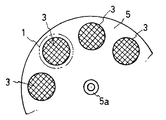
図2に示すように、フィルター3は、複数組が、交換用支持体5、5’に着脱可能にセットされ、それぞれ、前記交換用支持体の操作で、その1組が選択的に浮遊固形物回収領域4あるいは4’に挿入される。交換用支持体5、5’は、導管1外に支軸5a、5a’を備えた円盤状回転部材であり、その一部が、例えば、O−リング6を介して、浮遊固形物回収領域4、4’に液密に挿入される構造になっている。なお、管1を挟んで対向するバルク磁石2(あるいは2’、2”)は、真空容器(図示せず)内に収容されている。
【0017】
なお、ここでは、前記真空ポンプの働きで、断熱性を高めるため、真空容器内を真空状態にすると共に、前記小型冷凍機の働きで、真空容器中において、バルク磁石を、ヘリウムガスなどの冷媒を用いて、超低温(好ましくは、絶対温度4〜100度)に維持する。
【0018】
なお、図中、符号7、8は、導管1の、被処理水の導入側および導出側に、それぞれ、装備したゲートバルブである。
【0019】
このような構成では、ゲートバルブ7、8を開放した状態で、導管1に被処理水を流すと、前述のような、フィルター3による浮遊固形物の分離・回収を行うことができ、また、適時に、交換用支持体5、5’を回転して、当該フィルター3を導管1外に導出すると共に、新たなフィルター3を浮遊固形物回収領域4、4’に対応させることができる。
【0020】
従って、超伝導ソレノイドコイルを用いる場合のように、導管1内の被処理水の流れに沿って、十分な磁場を発生させることができ、しかも、バルク磁石を用いることで、超伝導ソレノイドを用いる設備に比較して、その設備を大幅に簡素化でき、低コストで提供できるメリットが得られる。しかも、運転を中断することなく、フィルター交換ができ、運転状態を実質的に継続することができ、稼働率を向上できる。
【0021】
なお、この実施の形態では、バルク磁石による磁場の発生、フィルターに捕捉した浮遊固形物の除去を簡潔に説明するために、単列の導管1での被処理水からの浮遊固形物の回収について、その構成および作用効果を示しているが、規模の大型化や補修などを配慮して、浮遊固形物の連続除去作業を維持するために、実際には、導管1を複列(少なくとも、2列)とし、そこに、それぞれ、浮遊固形物回収領域およびこれに対応するバルク磁石、支持部材による交換可能なフィルターなどを設けることが望ましい。
【0022】
【発明の効果】
本発明によれば、フィルターを用いた前記浮遊固形物回収領域を通る被処理水の全量に対して、全ての浮遊固形物の捕捉機能を十分に発揮できる上、前記フィルターの交換操作で、前記回収領域での磁場の発生、消滅を行わずに、実質的に継続作業を維持することができる。
【図面の簡単な説明】
【図1】本発明に係る実施の形態を示す概略平面図である。
【図2】同じく、フィルターの交換を可能とする交換用支持体の構成を示す概略正面図である。
【符号の説明】
1 導管(配管)
2、2’、2” バルク磁石
3 フィルター
4、4’ 浮遊固形物回収領域
5 交換用支持体
6 O−リング
7、8 ゲートバルブ[0001]
BACKGROUND OF THE INVENTION
The present invention is mainly a flocculant containing magnetic fine particles, and the contaminants in the water to be treated are made to be floating solids having magnetism, and the suspended solids are covered by the magnetic force in the flow of the water to be treated. The present invention relates to a purification device that separates from treated water.
[0002]
[Prior art]
In general, in the treatment of purified water (water, sewage, industrial wastewater), particularly when separating eutrophic sludge (mainly phosphorus-containing material) from the treated water, it was generated using a high gradient magnetic field. For example, it is a flocculant containing ferrite (powder or granular ferromagnet: hereinafter referred to as magnetic fine particles) such as magnetite. It is said.
[0003]
Then, the water to be treated in this state is led into a conduit made of a nonmagnetic material around which a superconducting solenoid coil is wound, and a magnetic field is generated in the conduit by energizing the superconducting solenoid coil. There has been proposed a purification device that filters the water to be treated through a filter placed therein, and then removes and collects suspended solids attached to the filter from the filter.
[0004]
This purification device is superior in that it generates a magnetic field in a direction parallel to the flow of water to be treated and has good separation efficiency of suspended solids by the filter. At the same time that the particles are trapped, the filter needs to be cleaned, while the magnetic field must be turned off.
[0005]
The problem here is that when a superconducting solenoid coil is used, the device becomes expensive. In particular, if it is a low-temperature superconducting solenoid, excitation and demagnetization require a long time (usually 30 minutes each). Therefore, in the separation work of suspended solids, the filter cleaning must be interrupted considerably long.
[0006]
[Problems to be solved by the invention]
The present invention has been made on the basis of the above circumstances, and the object of the present invention is to generate a magnetic field parallel to the flow of water to be treated when capturing suspended solids by magnetic force. In addition, it is possible to provide a purification device using a magnetic material at a low cost, which can exhibit high separation efficiency due to the above, and can replace the filter without interrupting the work.
[0007]
[Means for Solving the Problems]
For this reason, the purification apparatus using the magnetic material according to the present invention includes: (1) a flocculant containing magnetic fine particles, and the pollutant in the water to be treated is made a floating solid substance having magnetism, and the flow of the water to be treated is in the middle, by a magnetic force, the purifying device for separating the suspended solids from the water to be treated, (2) a conduit for straight Ri Do a non-magnetic material, with respect to the conduit flow the water to be treated inside Te, wherein at conduit in proximity to the outside across the conduit, are arranged a pair of bulk magnet as the magnetic pole surface while being opposed pole faces of the same polarity is parallel to the straight direction of the conduit A magnetic field including a portion parallel to the straight direction of the conduit is formed in the conduit; and (3) the floating solids flowing in the conduit are suspended in the middle of the conduit across the magnetic field. The suspended solids are captured in the solids collection area. Includes a filter to be inserted into the collection area, (4) the filter has a plurality of sets is set detachably on the replacement support, the operation of the exchange support, the set is selectively said (5) There are a plurality of pairs of the bulk magnets, arranged with a gap along the straight direction of the conduit, and the polarities of the opposing magnetic pole faces of the same polarity are arranged. the adjacent pairs being arranged so as to be opposite, (6) before Symbol replacement support is interposed in a gap of the pairs of the plurality of bulk magnets the adjacent, the suspended solids recovery area, the adjacent The inner region of the conduit corresponding to the gap between a plurality of pairs of bulk magnets .
[0008]
In such a configuration, the direction of the magnetic field by the magnet is along the flow of the water to be treated, and all the floating solids with respect to the total amount of the water to be treated that passes through the floating solid collection area using the filter. In addition to being able to fully perform the trapping function of the above, since the filter replacement can be performed instantly, the treatment work of the treated water by the bulk magnet can be performed continuously without substantial interruption, so when using a superconducting solenoid, In particular, unlike the case of using a low-temperature superconducting solenoid that takes time for excitation and demagnetization, there is no need to interrupt the operation for a considerable period of time, and continuous operation is possible, resulting in an advantage of improving the operating rate.
[0009]
In this case, as an embodiment of the present invention, it is preferable that a magnetic material is used as a material for the filter, and the filter material is braided with a required mesh. As an example in which the embodiment is expanded, it is effective to arrange the adjacent magnetic poles so that the directions of the magnetic poles facing each other are opposite to each other.
[0010]
Moreover, the replacement support is a disk-shaped rotating member provided with a support shaft outside the conduit, and a part of the support is configured to be liquid-tightly inserted into the floating solid collection region. This is a preferred embodiment.
[0011]
DETAILED DESCRIPTION OF THE INVENTION
Hereinafter, embodiments of the present invention will be specifically described with reference to the drawings. FIG. 1 is a plan view showing a schematic configuration, and FIG. 2 is a front view showing a disk-like rotating member equipped with a filter.
[0012]
The purification apparatus according to the present invention is a flocculant containing magnetic fine particles, and the contaminants in the water to be treated are made to be a floating solid substance S having magnetism. The object S is separated from the water W to be treated. Here, a magnetic field (indicated by a line of magnetic force M) along the flow with the same poles facing each other across the flow of water to be treated in the conduit 1 (pipe) made of a nonmagnetic material (for example, hard synthetic resin). ),
[0013]
The
[0014]
In this embodiment, the
[0015]
In this embodiment, a plurality of pairs of
[0016]
As shown in FIG. 2, a plurality of sets of
[0017]
Here, in order to improve heat insulation by the function of the vacuum pump, the inside of the vacuum container is evacuated and the bulk magnet is replaced with a refrigerant such as helium gas in the vacuum container by the function of the small refrigerator. Is maintained at an ultra-low temperature (preferably an absolute temperature of 4 to 100 degrees).
[0018]
In the figure,
[0019]
In such a configuration, when the water to be treated is allowed to flow through the
[0020]
Therefore, as in the case of using a superconducting solenoid coil, a sufficient magnetic field can be generated along the flow of water to be treated in the
[0021]
In this embodiment, in order to briefly explain the generation of the magnetic field by the bulk magnet and the removal of the suspended solids captured by the filter, the recovery of the suspended solids from the water to be treated in the single-
[0022]
【The invention's effect】
According to the present invention, with respect to the total amount of water to be treated that passes through the floating solids recovery area using a filter, it is possible to sufficiently exhibit the trapping function of all the floating solids, and in the replacement operation of the filter, The continuous operation can be substantially maintained without generating or extinguishing the magnetic field in the recovery region.
[Brief description of the drawings]
FIG. 1 is a schematic plan view showing an embodiment according to the present invention.
FIG. 2 is a schematic front view showing the configuration of a replacement support body that allows the filter to be replaced.
[Explanation of symbols]
1 Conduit (Piping)
2, 2 ', 2 "
Claims (3)
(2)非磁性材料からなり直進する導管であって、その内部に前記被処理水を流す導管に対して、前記導管の外部に近接して前記導管を挟んで、同一極性の磁極面を対向させた状態で前記磁極面が前記導管の直進方向に平行になるように一対のバルク磁石が配置されて、前記導管の直進方向に平行な部分を含む磁場が前記導管の内部に形成され、
(3)前記導管内を流れる前記浮遊固形物を、前記磁場を横切って前記導管の途中に設けられた浮遊固形物回収領域で捕捉するように、前記浮遊固形物回収領域に挿入されるフィルターを備えており、
(4)該フィルターは、複数組が交換用支持体に着脱可能にセットされ、前記交換用支持体の操作で、その1組が選択的に前記浮遊固形物回収領域に挿入され、
(5)前記バルク磁石の対は複数対あり、前記導管の直進方向に沿って間隙を保って配置され、それぞれの前記対向する同一極性の磁極面の極性が隣接する対とは反対となるように配置され、
(6)前記交換用支持体が前記隣接する複数のバルク磁石の対の間隙に介挿されて、前記浮遊固形物回収領域が、前記隣接する複数のバルク磁石の対の間隙に対応する前記導管の内部領域になることを特徴とする、磁性体を用いた浄化装置。 (1) A flocculant containing magnetic fine particles, and the pollutant in the water to be treated is made a floating solid with magnetism, and the suspended solid is separated from the water to be treated by magnetic force in the flow of the water to be treated. In the purification device to separate,
(2) a conduit for straight Ri Do a non-magnetic material, with respect to the conduit flow the water to be treated therein, proximate to the exterior of said conduit across the conduit, pole faces of the same polarity A pair of bulk magnets are arranged so that the magnetic pole faces are parallel to the straight direction of the conduit in a state where they face each other, and a magnetic field including a portion parallel to the straight direction of the conduit is formed inside the conduit. ,
(3) A filter inserted into the floating solid collection region so that the floating solid flowing in the conduit is captured by the floating solid collection region provided in the middle of the conduit across the magnetic field. Has
(4) A plurality of sets of the filters are detachably set on the replacement support, and one set is selectively inserted into the floating solid collection region by the operation of the replacement support.
(5) There are a plurality of pairs of the bulk magnets arranged with gaps along the straight direction of the conduit so that the polarities of the opposing magnetic pole faces of the same polarity are opposite to the adjacent pairs. Placed in
(6) before Symbol replacement support is interposed in a gap of the pairs of the plurality of bulk magnets the adjacent, the suspended solids recovery zone corresponds to the gap between the pair of the plurality of bulk magnets said adjacent said A purification device using a magnetic material, characterized in that it is an inner region of a conduit .
Priority Applications (1)
| Application Number | Priority Date | Filing Date | Title |
|---|---|---|---|
| JP2002141865A JP4009699B2 (en) | 2002-05-16 | 2002-05-16 | Purification device using magnetic material |
Applications Claiming Priority (1)
| Application Number | Priority Date | Filing Date | Title |
|---|---|---|---|
| JP2002141865A JP4009699B2 (en) | 2002-05-16 | 2002-05-16 | Purification device using magnetic material |
Publications (3)
| Publication Number | Publication Date |
|---|---|
| JP2003334564A JP2003334564A (en) | 2003-11-25 |
| JP2003334564A5 JP2003334564A5 (en) | 2005-09-22 |
| JP4009699B2 true JP4009699B2 (en) | 2007-11-21 |
Family
ID=29702333
Family Applications (1)
| Application Number | Title | Priority Date | Filing Date |
|---|---|---|---|
| JP2002141865A Expired - Fee Related JP4009699B2 (en) | 2002-05-16 | 2002-05-16 | Purification device using magnetic material |
Country Status (1)
| Country | Link |
|---|---|
| JP (1) | JP4009699B2 (en) |
Families Citing this family (3)
| Publication number | Priority date | Publication date | Assignee | Title |
|---|---|---|---|---|
| JP5172817B2 (en) * | 2009-12-14 | 2013-03-27 | 株式会社神戸製鋼所 | Magnetic field generator for physical treatment of water |
| EP2665112B1 (en) * | 2011-01-13 | 2016-11-16 | Toyota Jidosha Kabushiki Kaisha | Electrode material applying apparatus and filtering method |
| KR101988792B1 (en) * | 2018-03-05 | 2019-09-30 | 건국대학교 산학협력단 | Dust collecting device using magnetic force |
-
2002
- 2002-05-16 JP JP2002141865A patent/JP4009699B2/en not_active Expired - Fee Related
Also Published As
| Publication number | Publication date |
|---|---|
| JP2003334564A (en) | 2003-11-25 |
Similar Documents
| Publication | Publication Date | Title |
|---|---|---|
| EP0089200B1 (en) | A high-gradient magnetic separator | |
| EP0856359B1 (en) | Apparatus for magnetic purification | |
| JP4009699B2 (en) | Purification device using magnetic material | |
| DE50210315D1 (en) | HIGH GRADIENT MAGNETIC FILTERS AND METHOD FOR SEPARATING WEAK MAGNETIZABLE PARTICLES FROM LIQUID MEDIA | |
| JP3826199B2 (en) | Magnetic separation device | |
| JP4288555B2 (en) | Separation and purification device using magnetic material | |
| JP4206691B2 (en) | Purification device using magnetic material | |
| JP2011056369A (en) | Magnetic separator, and magnetic separation system | |
| JP3641657B2 (en) | Purification device using magnetic material | |
| JP2009119421A (en) | Magnetic separation apparatus | |
| JP3799390B2 (en) | Purification device using magnetic material | |
| JP2003080108A (en) | Purifier using magnetic material | |
| JP2007098297A (en) | Water purification system for drinking water | |
| JP5846536B2 (en) | Magnetic precipitation magnetic separation apparatus and magnetic separation method | |
| JP4129548B2 (en) | Continuous magnetic separator | |
| JP2009219988A (en) | Magnetic filter, and treated-liquid cleaning device | |
| JP3933516B2 (en) | Liquid magnetizer for use in flow path | |
| JP3314350B2 (en) | Purification device | |
| JPH10192619A (en) | Purifying device | |
| KR20130065400A (en) | Apparatus for purification of condenser wastewater of thermal power plant using superconducting magnetic separator | |
| JP3580117B2 (en) | Magnetic separation device | |
| JP2003334564A5 (en) | ||
| JP3788007B2 (en) | Purification device | |
| JPS6323707A (en) | Magnetic separator | |
| JP2002307069A (en) | Magnetic induction water cleaning apparatus |
Legal Events
| Date | Code | Title | Description |
|---|---|---|---|
| A711 | Notification of change in applicant |
Free format text: JAPANESE INTERMEDIATE CODE: A712 Effective date: 20031031 |
|
| RD03 | Notification of appointment of power of attorney |
Free format text: JAPANESE INTERMEDIATE CODE: A7423 Effective date: 20040129 |
|
| A521 | Written amendment |
Free format text: JAPANESE INTERMEDIATE CODE: A523 Effective date: 20050302 |
|
| A621 | Written request for application examination |
Free format text: JAPANESE INTERMEDIATE CODE: A621 Effective date: 20050302 |
|
| RD02 | Notification of acceptance of power of attorney |
Free format text: JAPANESE INTERMEDIATE CODE: A7422 Effective date: 20050331 |
|
| A521 | Written amendment |
Free format text: JAPANESE INTERMEDIATE CODE: A523 Effective date: 20050330 |
|
| A977 | Report on retrieval |
Free format text: JAPANESE INTERMEDIATE CODE: A971007 Effective date: 20070111 |
|
| A131 | Notification of reasons for refusal |
Free format text: JAPANESE INTERMEDIATE CODE: A131 Effective date: 20070130 |
|
| A521 | Written amendment |
Free format text: JAPANESE INTERMEDIATE CODE: A523 Effective date: 20070328 |
|
| A131 | Notification of reasons for refusal |
Free format text: JAPANESE INTERMEDIATE CODE: A131 Effective date: 20070424 |
|
| A521 | Written amendment |
Free format text: JAPANESE INTERMEDIATE CODE: A523 Effective date: 20070622 |
|
| TRDD | Decision of grant or rejection written | ||
| A01 | Written decision to grant a patent or to grant a registration (utility model) |
Free format text: JAPANESE INTERMEDIATE CODE: A01 Effective date: 20070731 |
|
| A61 | First payment of annual fees (during grant procedure) |
Free format text: JAPANESE INTERMEDIATE CODE: A61 Effective date: 20070807 |
|
| R150 | Certificate of patent or registration of utility model |
Free format text: JAPANESE INTERMEDIATE CODE: R150 |
|
| FPAY | Renewal fee payment (event date is renewal date of database) |
Free format text: PAYMENT UNTIL: 20100914 Year of fee payment: 3 |
|
| FPAY | Renewal fee payment (event date is renewal date of database) |
Free format text: PAYMENT UNTIL: 20110914 Year of fee payment: 4 |
|
| FPAY | Renewal fee payment (event date is renewal date of database) |
Free format text: PAYMENT UNTIL: 20120914 Year of fee payment: 5 |
|
| FPAY | Renewal fee payment (event date is renewal date of database) |
Free format text: PAYMENT UNTIL: 20120914 Year of fee payment: 5 |
|
| FPAY | Renewal fee payment (event date is renewal date of database) |
Free format text: PAYMENT UNTIL: 20130914 Year of fee payment: 6 |
|
| R250 | Receipt of annual fees |
Free format text: JAPANESE INTERMEDIATE CODE: R250 |
|
| R250 | Receipt of annual fees |
Free format text: JAPANESE INTERMEDIATE CODE: R250 |
|
| S533 | Written request for registration of change of name |
Free format text: JAPANESE INTERMEDIATE CODE: R313533 |
|
| R350 | Written notification of registration of transfer |
Free format text: JAPANESE INTERMEDIATE CODE: R350 |
|
| R250 | Receipt of annual fees |
Free format text: JAPANESE INTERMEDIATE CODE: R250 |
|
| R250 | Receipt of annual fees |
Free format text: JAPANESE INTERMEDIATE CODE: R250 |
|
| R250 | Receipt of annual fees |
Free format text: JAPANESE INTERMEDIATE CODE: R250 |
|
| LAPS | Cancellation because of no payment of annual fees |