JP4005366B2 - Vehicle seats especially for aircraft - Google Patents
Vehicle seats especially for aircraft Download PDFInfo
- Publication number
- JP4005366B2 JP4005366B2 JP2001578282A JP2001578282A JP4005366B2 JP 4005366 B2 JP4005366 B2 JP 4005366B2 JP 2001578282 A JP2001578282 A JP 2001578282A JP 2001578282 A JP2001578282 A JP 2001578282A JP 4005366 B2 JP4005366 B2 JP 4005366B2
- Authority
- JP
- Japan
- Prior art keywords
- bar
- seat
- component
- backrest
- vehicle seat
- Prior art date
- Legal status (The legal status is an assumption and is not a legal conclusion. Google has not performed a legal analysis and makes no representation as to the accuracy of the status listed.)
- Expired - Fee Related
Links
Images


Classifications
-
- B—PERFORMING OPERATIONS; TRANSPORTING
- B64—AIRCRAFT; AVIATION; COSMONAUTICS
- B64D—EQUIPMENT FOR FITTING IN OR TO AIRCRAFT; FLIGHT SUITS; PARACHUTES; ARRANGEMENTS OR MOUNTING OF POWER PLANTS OR PROPULSION TRANSMISSIONS IN AIRCRAFT
- B64D11/00—Passenger or crew accommodation; Flight-deck installations not otherwise provided for
- B64D11/06—Arrangements of seats, or adaptations or details specially adapted for aircraft seats
- B64D11/0639—Arrangements of seats, or adaptations or details specially adapted for aircraft seats with features for adjustment or converting of seats
- B64D11/064—Adjustable inclination or position of seats
-
- B—PERFORMING OPERATIONS; TRANSPORTING
- B60—VEHICLES IN GENERAL
- B60N—SEATS SPECIALLY ADAPTED FOR VEHICLES; VEHICLE PASSENGER ACCOMMODATION NOT OTHERWISE PROVIDED FOR
- B60N2/00—Seats specially adapted for vehicles; Arrangement or mounting of seats in vehicles
- B60N2/24—Seats specially adapted for vehicles; Arrangement or mounting of seats in vehicles for particular purposes or particular vehicles
- B60N2/32—Seats specially adapted for vehicles; Arrangement or mounting of seats in vehicles for particular purposes or particular vehicles convertible for other use
- B60N2/34—Seats specially adapted for vehicles; Arrangement or mounting of seats in vehicles for particular purposes or particular vehicles convertible for other use into a bed
-
- B—PERFORMING OPERATIONS; TRANSPORTING
- B60—VEHICLES IN GENERAL
- B60N—SEATS SPECIALLY ADAPTED FOR VEHICLES; VEHICLE PASSENGER ACCOMMODATION NOT OTHERWISE PROVIDED FOR
- B60N2/00—Seats specially adapted for vehicles; Arrangement or mounting of seats in vehicles
- B60N2/90—Details or parts not otherwise provided for
- B60N2/995—Lower-leg-rests, e.g. calf-rests
-
- B—PERFORMING OPERATIONS; TRANSPORTING
- B64—AIRCRAFT; AVIATION; COSMONAUTICS
- B64D—EQUIPMENT FOR FITTING IN OR TO AIRCRAFT; FLIGHT SUITS; PARACHUTES; ARRANGEMENTS OR MOUNTING OF POWER PLANTS OR PROPULSION TRANSMISSIONS IN AIRCRAFT
- B64D11/00—Passenger or crew accommodation; Flight-deck installations not otherwise provided for
- B64D11/06—Arrangements of seats, or adaptations or details specially adapted for aircraft seats
- B64D11/0639—Arrangements of seats, or adaptations or details specially adapted for aircraft seats with features for adjustment or converting of seats
- B64D11/06395—Arrangements of seats, or adaptations or details specially adapted for aircraft seats with features for adjustment or converting of seats characterised by the arrangement of electric motors for adjustment
-
- B—PERFORMING OPERATIONS; TRANSPORTING
- B64—AIRCRAFT; AVIATION; COSMONAUTICS
- B64D—EQUIPMENT FOR FITTING IN OR TO AIRCRAFT; FLIGHT SUITS; PARACHUTES; ARRANGEMENTS OR MOUNTING OF POWER PLANTS OR PROPULSION TRANSMISSIONS IN AIRCRAFT
- B64D11/00—Passenger or crew accommodation; Flight-deck installations not otherwise provided for
- B64D11/06—Arrangements of seats, or adaptations or details specially adapted for aircraft seats
- B64D11/0639—Arrangements of seats, or adaptations or details specially adapted for aircraft seats with features for adjustment or converting of seats
- B64D11/0641—Seats convertible into beds
Abstract
Description
【0001】
発明の属する技術分野
本発明は、少なくとも一つの調節装置によって互いに関して移動させることができる、シートコンポーネント及び背もたれを備え、各調節装置は、バータイプの支持フレームを介して少なくとも部分的に互いに接続された複数の可動ジョイントを有し、支持フレームは、航空機又はキャビンデッキに関して直角にシートコンポーネントを位置決めする個々のバー部を有し、シートコンポーネントは、最初の位置から少なくとも一つのさらなる位置へ移動させることができるように、及び、このさらなる位置から最初の位置へ移動させることができるように、支持フレームは、作動装置によって移動し、可動ジョイントは、バータイプの支持フレームの角点において少なくとも部分的に取り付けられており、背もたれとシートコンポーネントの間の移行領域において少なくとも一つの可動ジョイントが設けられている、特に航空機乗員シートなどの乗物シートに関する。
【0002】
従来の技術
例えばフェリーなどの船の旅行も含む長距離飛行に伴う特に非常に長い旅行において、航空機又はフェリーの旅行用品商の一般的な目的は、輸送されるシート乗員及び乗客の快適さを増すことである。特にファーストクラス及びビジネスクラスの領域の顧客は、シートが快適であることを望んでいる。したがって、長距離飛行の後に目的地に着いた時に疲労をなくすために、移動時間を例えば有意義な休息又は睡眠のために利用したい乗員の希望を取り入れる傾向がある。
【0003】
独国特許第675982号には、いわゆるガイドロッド平行四辺形に似たバータイプの支持フレームを有する一般的な航空機シートが開示されている。このガイドロッド平行四辺形により、垂直方向に調節することができる航空機パイロットシートを調節することができ、シートは、飛行方向と横断して取付られた軸線回りで回動可能であり、同時に、各垂直方向又は長手方向の設定時に横断軸線回りで別個に長手方向の調節ができる。それゆえ、従来の解決方法の場合において、上側強固バー部は、可動ジョイントを介してシートコンポーネント及び背もたれと接続されている。従来のバータイプの支持フレームの下側強固バー部は、シートレールの長手調節装置から、背もたれの後領域が可動ジョイントによって係合させられた他のバー部へ背もたれと平行に延びている。下側強固バー部は、さらに、端側で下側バー上に取り付けられた可動ジョイントによって、示した構造の構成要素に接続されている。従来のバータイプ支持フレームを使用すると、パイロットのシートの寸法が増大してしまい、クランプして据え付け状態で航空機のキャビン領域で使用することはそれほど合理的でない。さらに、調節の選択肢が非常に狭い範囲のみで設けられるように、バータイプの支持フレームはパイロットシートの可動シートコンポーネントと係合する。また、航空機パイロットがいかなる時にも望まない選択肢である、例えばスリーピング又はリクライニング位置の選択肢も排除される。特定の具体的な構造についての結果では、従来のバータイプの支持フレームは、衝突時にシート構造にもたらされる力を吸収することができない。したがって、衝突時の構造の欠陥が予測される。
【0004】
逆に、後で発行された欧州特許第1074468号には、背もたれの上側、シートコンポーネント及びレッグレストがほぼ水平なリクライニング面を形成するリクライニング位置及びスリーピング位置を含む、異なる位置をとることができる、顕著に改良された航空機乗員シートが開示されている。この解決手段の場合、作動装置によって背もたれを回動させるために種々の位置に伸縮させられうる、長手方向に調節可能なバー部は、背もたれの下側3分の1と係合している。
【0005】
さらに、この解決手段では、可動ジョイントとシートコンポーネントの間の移行領域において背もたれをシートコンポーネント上に可動ジョイントを介して取り付けることができる。移行領域における各可動ジョイントは、多少水平に延びている長手方向ガイド内において移動可能であり、航空機乗員シートの肘掛けの構成要素で構成されている。この構成要素は、静止するように取り付けられる時、両側において、別な方法で種々の位置に調節されうる乗員シートの長手側面の範囲を定める。もし別の作動機構が、端側でキャビンのデッキにヒンジ留めされかつ前領域でシートコンポーネントの底にヒンジ留めされる、前バー部と係合し、したがって、前バー部が回動するならば、シートは個々の位置に位置し、関連の長手方向ガイドによって肘掛けに沿って押される。その結果、欧州特許出願に開示されている解決手段は、いかなるバータイプの支持フレームも利用しておらず、むしろ、移動工程のための強制的な案内に依存している。後領域における背もたれの下側3分の1と係合する、後の可変長バー部を対角に取り付けた結果、後ろに隣接したシート乗員の脚領域が干渉されない又は損傷しないように、別個のカバーを介して可動コンポーネントを留める必要があるので、大きな空間が使用される。
【0006】
したがって、本発明の目的は、乗員の利便性及び座り心地についての高まる要求を満たし、かつシステムが構造的空間をほとんど取らず、かつ衝突安全性についてのより厳重な要求を満たすために、従来のシートシステムをさらに改良することである。このように記載した目的は、請求項1全体で記載された特徴を備えた乗物乗員シートによって得られる。
【0007】
請求項1の特徴部分によれば、各可動ジョイントは、移行領域において、シートコンポーネントに沿って延びている上側バー部の一端と、別の後バー部の端部に接続され、上側バー部の他端は、別の可動ジョイントを介して別の前バー部に接続され、後バー部及び前バー部は、床に関して少なくとも部分的に直角にシートコンポーネントを位置決めし、少なくとも前バー部又は後バー部は長手方向に調節可能であり、可能な移動の数、したがって、従来の解決手段に関する自由度は、導入される可動ジョイント及びバータイプの支持フレームのバー部の数の関数として顕著に増加し、シートコンポーネント及び背もたれを非常に広い範囲で位置決めすることができる。この解決手段では、強固でありかつ長手方向に部分的に調節可能なバーを有するバータイプの支持フレームは、移動コンセプト全体についての案内の機能を排他的に取り、調節性を本質的に制限するさらなる強制された案内は、全体的に放棄することができる。
【0008】
さらに、特許請求されたシートの移動により、コンポーネントを最初の位置に関して下降させるように、シートコンポーネントをさらなる位置の少なくとも一つに進行方向に移動させることができ、シートコンポーネントは、シート乗員のためのリクライニング位置に位置するように、傾斜位置に位置する。この工程では、バータイプの支持フレームが回動運動する結果、斜めに延びているリクライニング面全体がシート乗員用のリクライニング位置として実現されるように、背もたれがシートコンポーネントの傾斜に自動的に追従する。したがって、乗物又は航空機乗員シートの別の従来の機能は、休息又は睡眠用のフルスリーピング領域の機能に変えられる。この工程において、バータイプの支持フレームによって案内されるレッグレストは、シートコンポーネント及び背もたれの移動に自動的に追従する場合、斜めに延びている関連のリクライニング面は、足領域へ下方へ延び、前述のスリーピング領域を完成することができる。バータイプの支持フレーム全体がシートコンポーネントのほぼ下に位置するので、本発明の特許請求された解決手段は、構造的な空間を浪費せず、この点において、航空機等において存在する狭い据え付け空間の条件下で特に良好に適している。バー部を有するバータイプの支持フレームを製造すると、特に、背もたれが完全に直角である基位置において、任意の衝突力がシートにもたらされる場合に、バータイプの支持フレームの部分が離出する又はシートコンポーネントが崩壊して固定バータイプの支持フレームによって離されたままであることなく、力が確実に吸収され、乗物の床又はキャビンデッキに逸らすことができることをバーコンポーネントと共に保証する、小型の構造ユニットを生じる。
【0009】
好ましくは、最初の位置とリクライニング位置の間で、後シートコンポーネント面が前シートコンポーネント面に関して下げられる、少なくとも一つの他の快適位置を調節することができる。これは、例えば弛緩作用の助けとなり、したがって、シートコンポーネントを有する前側休息領域にある足のストレスが上昇位置によって軽減される。示している調節工程は、いくつかのコンポーネントのみで経済的に実施することができ、本発明で特許請求された乗物シートは、経済的に製造できかつ構造的に軽く、特に航空機において使用され、不必要な重量を避ける役割を有する。
【0010】
この用途の本発明において特許請求された乗物シートは、航空機乗員シートとしての用途に限定する必要がなく、例えばフェリーなどの乗員用船の運転、又は、列車やバスなどの他の態様の移動において使用することができる。
【0011】
好ましくは、使用されるアクチュエータは、空気式で駆動されて調節装置のための運動を生じ、選択的に、シート要素の互いに関する調節の過渡工程は、空気ダンパを有するピストンシリンダユニットによって緩和される。さらに、本発明の特許請求された乗物シートの一つの好適な実施例において、シートコンポーネント及び背もたれを少なくとも備えた調節装置は、モジュール式コンポーネントとして形成することができる。このモジュール式コンポーネントは、シートの側部などの他のシートコンポーネント要素や、例えば航空機内においてその場での一種のパレット搬送を介して次なるシートの使用のための肘掛けなどにおいて形成することができる。これは、例えば意図するシート数を同じ領域で増やす場合、本発明において特許請求された高級な乗物シートは、拡張したリクライニング位置なしで従来のシートに変更することができるという利点も有する。さらに、シートコンポーネント及びより激しく磨耗する背もたれは、清掃又は修理することができ、例えば、新しいカバー材料を備えてもよい。一方、磨耗しにくい又は汚れにくくかつ技術用語でコンパートメントと呼ばれるシートコンポーネントを例えば航空機などの各乗物内に配置することができ、非常に短い時間で、シートコンポーネント及び背もたれを有する新しい又は修繕した調節装置を備えうる。
【0012】
本発明において特許請求された乗物シートについての一実施例を用いて航空機の乗員シートを参照して以下に詳細に説明する。図面は略図的に示され、一定比では描かれていない。
【0013】
発明の実施の形態
図1〜3に示すように、航空機の乗員シートには、シートコンポーネント10と背もたれ12とが設けられている。ここでは詳細に説明しない従来の方法で、シートコンポーネント10及び背もたれ12の両方は、対応のカバーと、経済的に有利な座席形状とを有する。シートコンポーネント10及び背もたれ12の両方は、全体として14で示されている調節装置によって、互いに関して移動することができるように保持されている。調節装置14は、全体として18で示されているバータイプの支持フレームワークによって互いに接合されたいくつかの可動ジョイント16を有し、可動ジョイント16は、シートコンポーネント10と当接し、作動装置20によって、特に回動運動の形態で、進行方向に移動し、シートコンポーネント10は、図3に示す最初の位置Iから他の二つの位置II及びIII に移動させることができ、運動の方向を反転させることによって、シートコンポーネント10を再び最初の位置Iに戻すことができる。
【0014】
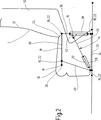
図2で特に示すように、バータイプの支持フレームワーク18の四つの角点22上において四つの可動ジョイント16があり、背もたれ12とシートコンポーネント10の間にある移行領域24において、少なくとも一つの可動ジョイント16がある。当該移行領域24において、示されている一つの可動ジョイント16は、シートコンポーネントの取付具等やシートコンポーネントの部品と係合することができる。このシートコンポーネントの取付具等は、シートコンポーネント10と背もたれ12の間で、所望の調節移動において強制的に案内する。
【0015】
バータイプの支持フレームワーク18は、長さが調節可能であり、かつアクチュエータ28と相互作用するバー部26を有する。アクチュエータ28は、図2において線で見られるように、好ましくは、空気ピストンシリンダユニットの形態であり、上側の強固なバー部30と、上側バー部30の下にある、バータイプの支持フレームワーク18内の下側の強固なバー部32との間において斜めに延びている。上側の強固なバー部30は、シートコンポーネント10内に嵌め込まれ、このようにシートコンポーネント10の周縁に詰め込まれている。しかしながら、このシートコンポーネント10の延伸によって、可動ジョイント16と、割り当て可能なバータイプの支持フレームワーク18は、自由な所望の移動時に妨げられない。上側の強固なバー部30と同様に、下側の強固なバー部32は、その長さを調節又は変化させることができない。下側のバー部32は、航空機のデッキの部分に接続された従来のシートレール34によって、航空機の乗員シートをデッキ領域に対して直角に位置決めするために使用されている。正面の端部において上側のバー部30の延長部において、シートコンポーネント10との連結ポイント35としての別の可動ジョイント16がある。
【0016】
バータイプの支持フレームワーク18は別の背バー部36を有する。この背バー部36は、その長さを調節することができ、バー部26の形態の作動部を有するアクチュエータ28が別の可動ジョイント16によって係合する調整部38と相互作用する。示されたアクチュエータ28の反対の端部は、下側の強固なバー部32の前可動ジョイント16に接続されている。下側バー部32のこの可動ジョイント16は、別の強固な前バー部40によって、上側バー部30の割り当てられた、下の可動ジョイント16にヒンジ留めされている。この前バー部40の上側の強固なバー部30への連結は、バータイプの支持フレームワーク18の前側の上側角点22を保持する可動ジョイント16によって行う。しかしながら、調整部38は、アクチュエータ28と同様に、本実施例では空気制御装置を有し、シートをバータイプの支持フレームワーク18で調節する時に望ましくない振動運動を打ち消す。従来技術におけるこの種の制御装置及びピストンシリンダユニットは、車両シートの領域における調節手段として公知であるので、本明細書では詳細に記載しない。
【0017】
全体的に18で示されるバータイプの支持フレームワークは、全体的に14で示される調節装置と同様に、乗物シート要素と容易に係合することができる。しかしながら、図2に示すように、特に図面の平面の前後における連続的な構成において、記載した構成が、例えば、シートの二つの長手縁の領域において、二回以上一致して存在し、クロスバーと一致して連続して配置される可動ジョイント16を留めることによって、一つのバータイプの支持フレームワーク18(詳細に説明しない)が一度にアクチュエータ28によって中央位置から作動させることができる。バータイプの支持フレームワーク18が横断方向、それゆえ、シート面の横断方向に続き、シート構造の留めの一助となれば有利である。バータイプの支持フレームワーク18の示されているバー部分は、バー状又は管状である必要がないが、例えば、アルミニウムダイカスト材料等の幾何学的形状の支持部材からなりうる。
【0018】
図2に示すように、航空機の乗員シートの最初の位置Iでは、バータイプの支持フレームワーク18は台形状となるように作られており、この台形の二つの基線は、互いに平行に延びており、上側の強固なバー部30と下側の強固なバー部32で形成されている。互いに平行でない台形の辺は、バー部40と、調整部38を有するバー部36とで形成される。入れ子式バー部26によってアクチュエータ28を調整部38のハウジングに係合するために、バー状三角レシーバ42が使用され、このレシーバ42には、自由端において、バー部26への移行のための可動ジョイント16が設けられている。最初の位置Iにおいて、シートレール34又は航空機の取り付けデッキに向かう調整部38を有する後バー部36は90°の角度を含む。逆に、アクチュエータ28を有するバー部26と水平のシートレール34又はデッキの間の角度は約30°である。
【0019】
好ましくは、シートの乗員がシート調節を行うために詳細に説明しない作動装置を介してアクチュエータ28を作動開始する場合、空気圧により、バー部26がアクチュエータ28内に引かれ、その結果、バー部40と、調整部38を有するバー部36は、バータイプの支持フレームワーク18のシートレール34への移行領域内の下側可動ジョイント16回りで反時計回りに回動し、上側バー部30を介してこの移動を行う際、図3において線で見られるように、例えば快適位置IIに到達するまで、シートコンポーネント10を前方及び下方に伴出する。この快適位置IIにおいて、示しているように、後シートコンポーネント面が前シートコンポーネント面に関して下げられ、詳細に説明しないシートコンポーネント取付具によって、バータイプの支持フレームワーク18の角点22上の後上側可動ジョイント16は、背もたれが図3に示す傾斜位置に到達するように、背もたれ12を伴出する。このタイプの移動を行うために、背バー部36は延伸させられ、好ましくは限定可能な距離だけ調整部38で減衰させられる。さらに、関連の進行方向の移動において、調整部38は底可動ジョイント16回りで反時計回りで回動し、アクチュエータ28は所定距離だけ下可動ジョイント22回りで時計回りで回動する。
【0020】
この工程を続けると、リクライニング位置III におけるシートコンポーネント10は傾斜位置にあり、背もたれ12は、バータイプの支持フレームワーク18の回動運動による前述の案内により、シートコンポーネント10の傾斜に追従し、シート乗員のために斜めに延びているリクライニング面44(図1参照)全体が得られ、シートが位置する床面に関する当該リクライニング面44は約15°の角度を含み、この角度は、当該リクライニング面44がレッグレスト46を経由して又は実際に下方へ床の方向に延伸させられる程度である。レッグレスト46自体は、例えば示していない対応の取付部によって同様に案内され、リクライニング面44を斜めに延ばすために、シートコンポーネント10及び背もたれ12の移動に追従しうる。その際、底端に向いたレッグレスト46はカーフレスト48を有することができ、背もたれ12は、好ましくは、図1に示されているように、リクライニング又はスリーピング位置III においてシート乗員の頭を収容しかつ支持するための頭受け50と一体化している。
【0021】
異なる位置I、II及びIII は、バータイプの支持フレームワーク18と、駆動モータ28又は調整部38の形態のトリミングモータを有する調節装置14とについての示されたシートの移動で逆にすることができる。その際、バータイプの支持フレームワーク18として本質的に四つのバー機構が適用され、支持フレームワーク18は、特に経済的に実施することができ、例えば事故などの場合、力をシートの基フレームに逸らすことができる。示した空気式コンポーネント28及び38の代りに、例えば、電気モータ及び軸駆動の形態の他の駆動手段によってモータ及びトリム機能を得ることができる。
【0022】
示したように、シートレベルのスリーピング又はリクライニング位置III への下降に基づいて、斜め下方に傾斜したシートコンポーネント10の領域において、乗り越えるための高さを低くすることができ、同列の別のシートの乗員のために、必要な時に迷惑をかけることなく同列でリクライニングしている人を乗り越えることができる。四つのバー機構において微小の調節運動で、非常に広範に変化させて調節して乗物シートを変更させることができ、かつ短い回動及び進行運動による各調節を迅速に完了することができるように、台形の支持フレームワーク18による運動は形成されている。特にバー部40及び36を前後に単に回動させることにより、広範な調節範囲を両方向において実現することができる。
【0023】
シートの使用のための側シートコンポーネント52(図1参照)などの他のシートコンポーネントにその場で分離可能に接続されることができる、モジュール式の構成要素をシートコンポーネント10、背もたれ12及びレッグレスト46と共に形成する調節装置14はさらに特に有利である。それゆえ、航空機内のコンパートメントの要領で側シートコンポーネント52を配置し、例えば修繕工程で位置I〜III を保証する機能ユニットのみを交換することができる。示しているコンパートメントは、側シートコンポーネントの場合に多数の機能を実施することができ、さらに、多大なプライバシー保護が可能となるシート乗員用の完全独立の領域(図示せず)を確保するように形成されることができ、バーの領域、洗濯設備などをコンパートメントに追加することも全く可能である。さらに、コンピュータや手帳用の特別な接続などの装置は、関連の完全独立の領域内でリクライニング及びスリーピングのための施設を有する作業場を形成する助けとなる。特に長旅の乗員は、このように助けられ、疲労を有効にとることができる。
【図面の簡単な説明】
【図1】 航空機の乗員の一部が航空機乗員シートに座っており、乗員の一人は、リクライニング位置でスタンディング及びリクライニングシートにおいてシートの寸法及び構成を考えている様子を示す図である。
【図2】 シートの移動及び航空機乗員シート自体の重要な部分を示す側面図である。
【図3】 異なる位置における図2に示す航空機乗員シートを示す図である。[0001]
The present invention comprises a seat component and a backrest that can be moved relative to each other by at least one adjusting device, each adjusting device being connected at least partly to each other via a bar-type support frame. A plurality of movable joints, the support frame has individual bar portions for positioning the seat component at right angles with respect to the aircraft or cabin deck, the seat component being moved from the initial position to at least one further position The support frame is moved by the actuator and the movable joint is at least partially at the corner points of the bar-type support frame so that it can be moved from this further position to the initial position. Attached, backrest and In particular, it relates to a vehicle seat, such as an aircraft occupant seat, in which at least one movable joint is provided in the transition region between the vehicle components .
[0002]
In particularly very long trips involving long distance flights including prior art, for example, boat trips such as ferries, the general purpose of an aircraft or ferry travel equipment merchant is to increase the comfort of the seat occupants and passengers transported That is. Customers in the first and business class areas in particular want a comfortable seat. Thus, to eliminate fatigue when arriving at the destination after a long flight, there is a tendency to incorporate the desire of the occupant who wishes to use travel time, for example for meaningful rest or sleep.
[0003]
German Patent No. 675982 discloses a general aircraft seat having a bar-type support frame resembling a so-called guide rod parallelogram. This guide rod parallelogram allows adjustment of the aircraft pilot seat, which can be adjusted in the vertical direction, and the seat can be rotated about an axis mounted transverse to the flight direction, Separate longitudinal adjustments can be made around the transverse axis when setting the vertical or longitudinal direction. Therefore, in the case of the conventional solution, the upper rigid bar is connected to the seat component and the backrest via a movable joint. The lower rigid bar portion of the conventional bar-type support frame extends parallel to the backrest from the seat rail length adjustment device to the other bar portion with the rear region of the backrest engaged by a movable joint. The lower rigid bar portion is further connected to the components of the structure shown by a movable joint attached on the lower bar at the end side. The use of a conventional bar-type support frame increases the size of the pilot's seat and is not very reasonable to clamp and use in the aircraft cabin area. Furthermore, the bar-type support frame engages with the movable seat component of the pilot seat so that only a very narrow range of adjustment options are provided. Also excluded are options that the aircraft pilot does not want at any time, such as sleeping or reclining positions. As a result of certain specific structures, conventional bar-type support frames are unable to absorb the forces that are exerted on the seat structure upon impact. Therefore, structural defects at the time of collision are predicted.
[0004]
Conversely, the later issued European Patent No. 1074468 can take different positions, including a reclining position and a sleeping position where the upper backrest, seat components and leg rest form a substantially horizontal reclining surface, A significantly improved aircraft occupant seat is disclosed. In the case of this solution, a longitudinally adjustable bar which can be extended and retracted to various positions for rotating the backrest by means of an actuating device is engaged with the lower third of the backrest.
[0005]
Furthermore, with this solution, the backrest can be mounted on the seat component via the movable joint in the transition region between the movable joint and the seat component. Each movable joint in the transition area is movable in a longitudinal guide that extends somewhat horizontally and consists of an armrest component of an aircraft occupant seat. This component delimits the longitudinal side of the occupant seat that can be adjusted to various positions in different ways on both sides when mounted stationary. If another actuating mechanism engages the front bar, which is hinged to the deck of the cabin at the end and hinged to the bottom of the seat component in the front region, and therefore the front bar rotates , The sheet is located in an individual position and is pushed along the armrest by an associated longitudinal guide. As a result, the solution disclosed in the European patent application does not utilize any bar-type support frame, but rather relies on forced guidance for the moving process. A separate variable length bar that engages the lower third of the backrest in the rear region, as a result of the diagonal mounting, so that the rear adjacent seat occupant leg region is not interfered or damaged A large space is used because it is necessary to fasten the movable component through the cover.
[0006]
Accordingly, the object of the present invention is to satisfy the increasing demands for passenger convenience and sitting comfort, and for the system to take up little structural space and to meet the more stringent requirements for crash safety. It is to further improve the seat system. The object thus described is obtained by a vehicle occupant seat having the features described in claim 1 as a whole.
[0007]
According to the characterizing portion of claim 1, each movable joint is connected to one end of the upper bar portion extending along the seat component and the end of another rear bar portion in the transition region, The other end is connected to another front bar part via another movable joint, the rear bar part and the front bar part positioning the seat component at least partially perpendicular to the floor, at least the front bar part or the rear bar part The part is adjustable in the longitudinal direction, and the number of possible movements, and thus the freedom with respect to conventional solutions, increases significantly as a function of the number of bar parts of the movable joint and bar-type support frame introduced. The seat component and the backrest can be positioned in a very wide range. In this solution, a bar-type support frame with a strong and partially adjustable bar in the longitudinal direction exclusively takes the guiding function for the entire movement concept and essentially limits the adjustability Further forced guidance can be totally abandoned.
[0008]
Further, the claimed movement of the seat can cause the seat component to move in at least one of the further positions in the direction of travel so that the component is lowered with respect to the initial position, the seat component being for the seat occupant It is located at an inclined position so as to be located at a reclining position. In this process, the backrest automatically follows the inclination of the seat components so that the entire tilting reclining surface is realized as a reclining position for the seat occupant as a result of the pivotal movement of the bar-type support frame. . Thus, another conventional function of the vehicle or aircraft occupant seat is converted to the function of a full sleeping area for rest or sleep. In this process, if the legrest guided by the bar-type support frame automatically follows the movement of the seat component and the backrest, the associated reclining surface extending diagonally extends downward to the foot region, The sleeping area can be completed. Since the entire bar-type support frame is located substantially below the seat component, the claimed solution of the present invention does not waste structural space, and in this respect, the narrow installation space present in aircraft and the like. Particularly well suited under the conditions. When manufacturing a bar-type support frame with a bar part, the part of the bar-type support frame is released, especially if any impact force is exerted on the seat, at a base position where the backrest is completely perpendicular. A compact structural unit that ensures that the force can be absorbed and diverted to the vehicle floor or cabin deck without the seat component collapsing and being separated by a fixed bar type support frame Produce.
[0009]
Preferably, between the initial position and the reclining position, at least one other comfort position can be adjusted in which the rear seat component surface is lowered with respect to the front seat component surface. This helps, for example, a relaxing action, so that the stress of the foot in the front rest area with the seat component is reduced by the raised position. The adjustment process shown can be carried out economically with only a few components, and the vehicle seat claimed in the present invention can be produced economically and is structurally light, in particular used in aircraft, It has the role of avoiding unnecessary weight.
[0010]
The vehicle seat claimed in the present invention for this use need not be limited to use as an aircraft occupant seat; for example, in the operation of a passenger ship such as a ferry, or in other modes of movement such as a train or bus Can be used.
[0011]
Preferably, the actuator used is pneumatically driven to produce movement for the adjusting device, optionally the transitional process of adjusting the seat elements relative to one another is mitigated by a piston cylinder unit having an air damper. . Furthermore, in one preferred embodiment of the claimed vehicle seat of the present invention, the adjustment device comprising at least a seat component and a backrest can be formed as a modular component. This modular component can be formed in other seat component elements such as the sides of the seat, for example in an armrest for the use of the next seat via a kind of pallet transport in situ in the aircraft . This also has the advantage that, for example, when the intended number of seats is increased in the same region, the high-grade vehicle seat claimed in the present invention can be changed to a conventional seat without an extended reclining position. In addition, the seat components and the more heavily worn backrest can be cleaned or repaired and may be provided with new cover material, for example. On the other hand, a new or repaired adjustment device with a seat component and a backrest that can be placed in each vehicle , such as an aircraft, for example, in a vehicle that is hard to wear or dirty and that is called a compartment in technical terms. Can be provided.
[0012]
The invention will be described in detail below with reference to an aircraft passenger seat using one embodiment of the claimed vehicle seat in the present invention. The drawings are shown schematically and are not drawn to scale.
[0013]
Embodiments of the Invention As shown in FIGS. 1 to 3, a
[0014]
As particularly shown in FIG. 2, there are four
[0015]
The bar-
[0016]
The bar-
[0017]
A bar-type support framework, generally indicated at 18, can be easily engaged with a vehicle seat element, similar to the adjustment device indicated generally at 14. However, as shown in FIG. 2, particularly in a continuous configuration before and after the plane of the drawing, the described configuration is present more than once in the region of the two longitudinal edges of the sheet, for example, By fastening the movable joint 16 which is arranged in tandem with one another, one bar-type support framework 18 (not described in detail) can be actuated from the central position by the
[0018]
As shown in FIG. 2, in the first position I of the passenger seat of the aircraft, the bar-
[0019]
Preferably, when the seat occupant initiates actuation of the
[0020]
If this process is continued, the
[0021]
The different positions I, II and III can be reversed with the indicated sheet movement for the bar-
[0022]
As shown, on the basis of seat level sleeping or descending to the reclining position III, in the region of the
[0023]
Modular components that can be detachably connected in-situ to other seat components, such as side seat component 52 (see FIG. 1) for use of the seat, include
[Brief description of the drawings]
FIG. 1 is a diagram showing a state in which a part of an aircraft occupant sits on an aircraft occupant seat, and one of the occupants considers the size and configuration of the seat in the standing and reclining seats at the reclining position.
FIG. 2 is a side view showing the important parts of the seat movement and the aircraft occupant seat itself.
3 shows the aircraft occupant seat shown in FIG. 2 at different positions.
Claims (9)
前記移行領域(24)における前記各可動ジョイント(16)は、前記シートコンポーネント(10)に沿って長手方向に延びている前記上側バー部(30)の一端と、別の後バー部(36)の一端の両方に接続されており、前記上側バー部(30)の他端は、別の可動ジョイント(16)によって別の前バー部(40)に接続され、前記後バー部(36)及び前記前バー部(40)は、前記シートコンポーネント(10)を少なくとも部分的に床に関して直角に位置決めし、少なくとも前記前バー部(40)又は前記後バー部(36)の長さを調節することができることを特徴とする乗物シート。It comprises a seat component (10) and a backrest (12) that can be moved relative to each other by means of at least one adjustment device (14), each said adjustment device (14) via a bar-type support framework (18). A plurality of movable joints (16) connected at least partially to each other, said support framework (18) positioning individual seat parts (26) for positioning the seat component (10) at right angles with respect to the aircraft or cabin deck , 30, 32, 36, 40) so that the sheet component (10) can be moved from an initial position (I) to at least one other position (II, III) and the sheet component (10) can be moved from the other position (II, III) to the first position (I) Thus, the support framework (18) is moved by an actuator (20), and the plurality of movable joints (16) are at least partially at the corner points (22) of the bar-type support framework (18). In a vehicle seat, mounted and provided with at least one movable joint in a transition region (24) between the backrest (12) and the seat component (10),
Each movable joint (16) in the transition region (24) has one end of the upper bar portion (30) extending longitudinally along the seat component (10) and another rear bar portion (36). The other end of the upper bar part (30) is connected to another front bar part (40) by another movable joint (16), and the rear bar part (36) and The front bar portion (40) positions the seat component (10) at least partially perpendicular to the floor and adjusts at least the length of the front bar portion (40) or the rear bar portion (36). A vehicle seat characterized by
Applications Claiming Priority (3)
| Application Number | Priority Date | Filing Date | Title |
|---|---|---|---|
| DE10019484A DE10019484A1 (en) | 2000-04-19 | 2000-04-19 | Vehicle seat, in particular passenger seat |
| DE10019484.2 | 2000-04-19 | ||
| PCT/EP2001/004388 WO2001081172A1 (en) | 2000-04-19 | 2001-04-18 | Vehicle seat, especially for aircraft |
Publications (3)
| Publication Number | Publication Date |
|---|---|
| JP2003530979A JP2003530979A (en) | 2003-10-21 |
| JP2003530979A5 JP2003530979A5 (en) | 2005-09-22 |
| JP4005366B2 true JP4005366B2 (en) | 2007-11-07 |
Family
ID=7639370
Family Applications (1)
| Application Number | Title | Priority Date | Filing Date |
|---|---|---|---|
| JP2001578282A Expired - Fee Related JP4005366B2 (en) | 2000-04-19 | 2001-04-18 | Vehicle seats especially for aircraft |
Country Status (6)
| Country | Link |
|---|---|
| US (1) | US6769739B2 (en) |
| EP (1) | EP1274624B1 (en) |
| JP (1) | JP4005366B2 (en) |
| AT (1) | ATE257110T1 (en) |
| DE (2) | DE10019484A1 (en) |
| WO (1) | WO2001081172A1 (en) |
Cited By (1)
| Publication number | Priority date | Publication date | Assignee | Title |
|---|---|---|---|---|
| WO2015170428A1 (en) * | 2014-05-09 | 2015-11-12 | 株式会社ジャムコ | Aircraft passenger seat |
Families Citing this family (40)
| Publication number | Priority date | Publication date | Assignee | Title |
|---|---|---|---|---|
| FR2824025B1 (en) * | 2001-04-30 | 2003-09-26 | Sicma Aero Seat | SEAT IN PARTICULAR FOR AIRPLANES COMPRISING AN ADJUSTABLE BACK AND SEAT |
| CA2581738C (en) | 2001-08-09 | 2009-04-14 | Virgin Atlantic Airways Limited | A seating system and a passenger accomodation unit for a vehicle |
| DE10215028A1 (en) * | 2002-04-05 | 2003-10-30 | Recaro Aircraft Seating Gmbh | Seat, in particular passenger seat |
| DE10224048B4 (en) * | 2002-05-31 | 2006-07-13 | Airbus Deutschland Gmbh | Passenger seat, especially for a commercial aircraft |
| DE10308454A1 (en) * | 2003-02-24 | 2004-09-09 | Recaro Aircraft Seating Gmbh & Co. Kg | Seat, in particular aircraft or vehicle seat |
| DE10351692A1 (en) | 2003-11-05 | 2005-06-16 | Recaro Aircraft Seating Gmbh & Co. Kg | Seat, in particular passenger seat |
| US7131698B2 (en) * | 2003-12-15 | 2006-11-07 | Be Aerospace, Inc. | Vehicle passenger seat with adjustable headrest |
| US20050127740A1 (en) * | 2003-12-15 | 2005-06-16 | Be Aerospace, Inc. | Vehicle seating with integral passenger seat restraints |
| US7055904B2 (en) * | 2003-12-15 | 2006-06-06 | Be Aerospace, Inc. | Vehicle seating adapted for sleeping posture |
| US7134729B2 (en) * | 2003-12-15 | 2006-11-14 | Be Aerospace, Inc. | Frame assembly for vehicle passenger seat |
| US20060006704A1 (en) * | 2003-12-15 | 2006-01-12 | Be Aerospace, Inc. | Vehicle seating with storage feature |
| US7111904B2 (en) * | 2003-12-15 | 2006-09-26 | Be Aerospace, Inc. | Vehicle seating supporting a perch position |
| US20050151405A1 (en) * | 2003-12-15 | 2005-07-14 | Be Aerospace, Inc. | Vehicle seating with protected living space |
| DE102004004874A1 (en) * | 2004-01-30 | 2005-08-25 | Recaro Aircraft Seating Gmbh & Co. Kg | Seat, in particular passenger seat |
| DE102004019299B4 (en) * | 2004-04-15 | 2007-07-19 | Recaro Aircraft Seating Gmbh & Co. Kg | Vehicle seat, in particular passenger seat |
| DE102004026023A1 (en) * | 2004-05-27 | 2005-12-22 | Recaro Aircraft Seating Gmbh & Co. Kg | Seat, in particular passenger seat |
| DE102005022165B4 (en) | 2005-05-13 | 2007-05-03 | Recaro Aircraft Seating Gmbh & Co. Kg | Seat, in particular passenger seat |
| DE102005027375B3 (en) | 2005-06-14 | 2006-10-19 | Recaro Aircraft Seating Gmbh & Co. Kg | Seat used as an aircraft passenger seat comprises a seat part, a backrest and a shell element forming a partial enclosure of the seat part and/or the backrest |
| US20070045468A1 (en) * | 2005-08-26 | 2007-03-01 | Casey Paul T | Transporting airline passengers comfortably and efficiently on long distance flights |
| US7578470B2 (en) * | 2006-04-21 | 2009-08-25 | Be Aerospace, Inc. | Passenger seating arrangement |
| DE102006040059A1 (en) | 2006-08-26 | 2008-02-28 | Recaro Aircraft Seating Gmbh & Co. Kg | structural frame |
| SE530557C2 (en) | 2006-11-08 | 2008-07-08 | Scania Cv Abp | vehicle Seat |
| JP4435215B2 (en) * | 2007-07-19 | 2010-03-17 | 三洋電機株式会社 | Chair type massage machine |
| US20090146004A1 (en) * | 2007-12-06 | 2009-06-11 | B E Aerospace, Inc. | Aircraft seating arrangement and seat |
| US7950743B2 (en) * | 2008-02-05 | 2011-05-31 | Mark Kirgiss Clausen | Leg rest for economy class transportation seat |
| US8118365B2 (en) * | 2008-03-25 | 2012-02-21 | Henshaw Robert J | Vehicle seating |
| WO2012164391A1 (en) * | 2011-05-31 | 2012-12-06 | Societe Industrielle Et Commerciale De Materiel Aeronautique | Passenger seat |
| US9714862B2 (en) | 2011-10-07 | 2017-07-25 | Bombardier Inc. | Aircraft seat |
| US9592914B2 (en) | 2011-10-07 | 2017-03-14 | Bombardier Inc. | Aircraft seat |
| US9714095B2 (en) | 2011-10-07 | 2017-07-25 | Bombardier Inc. | Aircraft seat |
| US9073453B2 (en) | 2011-10-07 | 2015-07-07 | Bombardier Inc. | Aircraft seat |
| BE1020730A3 (en) * | 2013-02-04 | 2014-04-01 | Hool Nv Van | DEVICE OF A SEAT VEHICLE AND ADJUSTABLE SEAT FOR THIS. |
| EP2983563B1 (en) * | 2013-04-08 | 2019-09-25 | B/E Aerospace, Inc. | Vehicle seat with simultaneous articulation of seat pan and seat back |
| CA2935290C (en) | 2013-12-30 | 2021-10-12 | Bombardier Inc. | Aircraft seat |
| CA2962585C (en) | 2014-09-25 | 2022-07-26 | Bombardier Inc. | Aircraft seat |
| GB2530554A (en) | 2014-09-26 | 2016-03-30 | Bombardier Inc | Aircraft seat |
| GB2530556A (en) | 2014-09-26 | 2016-03-30 | Bombardier Inc | Aircraft seat |
| GB2539913B (en) * | 2015-06-30 | 2019-10-02 | British Airways Plc | Aircraft passenger seat mechanism |
| US10370109B2 (en) * | 2017-04-28 | 2019-08-06 | Enrique Juan Fortin | Non-intrusive and reclining seating arrangement for an airplane or other means of transportation |
| EP3536614B1 (en) * | 2018-03-06 | 2020-12-09 | Bombardier Inc. | Passenger seat for aircraft |
Family Cites Families (15)
| Publication number | Priority date | Publication date | Assignee | Title |
|---|---|---|---|---|
| DE675982C (en) | 1937-04-10 | 1939-05-23 | Blohm & Voss | Height-adjustable driver's seat for aircraft |
| US2629425A (en) * | 1946-06-18 | 1953-02-24 | Boeing Co | Berthable chair |
| US4058342A (en) * | 1975-11-14 | 1977-11-15 | Ettridge John P | Child's car seat |
| US4104747A (en) * | 1977-04-14 | 1978-08-08 | General Engineering And Mfg. Corporation | Convertible sofa and bed structure |
| JPS5526905A (en) * | 1978-08-12 | 1980-02-26 | Onishi Tetsuo | Hair used both as bed or cart* etc* for patient or combination mechanism of wheelchair* etc* |
| US4333681A (en) * | 1979-11-16 | 1982-06-08 | Nelson M Eugene | Power operated reclining wheelchair |
| US4492407A (en) * | 1982-07-19 | 1985-01-08 | Syntex (U.S.A.) Inc. | Patient support and transverse motion linkage therefor |
| DE3364743D1 (en) * | 1982-10-28 | 1986-08-28 | Flight Equip & Eng | Vehicle seats |
| DE3725462A1 (en) * | 1987-07-31 | 1989-02-09 | Percival Lafer | Adjustable armchair |
| FR2692529B1 (en) * | 1992-06-18 | 1994-09-16 | Faure Bertrand Automobile | Improvements to vehicle seats with multiple settings. |
| US5611594A (en) * | 1995-04-13 | 1997-03-18 | Findlay; Robert | Portable folding chair |
| US5886461A (en) * | 1995-10-24 | 1999-03-23 | Micron Display Technology, Inc. | Transparent conductor for field emission displays |
| DE19607060C1 (en) * | 1996-02-24 | 1997-04-10 | Keiper Recaro Gmbh Co | Seat for motor vehicle, especially rear seat, or rear bench seat |
| US6227489B1 (en) * | 1998-05-15 | 2001-05-08 | Koito Industries, Ltd. | Aircraft seat apparatus |
| GB9918263D0 (en) | 1999-08-04 | 1999-10-06 | Britax Rumbold Ltd | Seating unit of a passenger vehicle |
-
2000
- 2000-04-19 DE DE10019484A patent/DE10019484A1/en not_active Withdrawn
-
2001
- 2001-04-18 DE DE50101268T patent/DE50101268D1/en not_active Expired - Lifetime
- 2001-04-18 EP EP01929574A patent/EP1274624B1/en not_active Expired - Lifetime
- 2001-04-18 WO PCT/EP2001/004388 patent/WO2001081172A1/en active IP Right Grant
- 2001-04-18 AT AT01929574T patent/ATE257110T1/en not_active IP Right Cessation
- 2001-04-18 JP JP2001578282A patent/JP4005366B2/en not_active Expired - Fee Related
- 2001-04-18 US US10/240,320 patent/US6769739B2/en not_active Expired - Fee Related
Cited By (2)
| Publication number | Priority date | Publication date | Assignee | Title |
|---|---|---|---|---|
| WO2015170428A1 (en) * | 2014-05-09 | 2015-11-12 | 株式会社ジャムコ | Aircraft passenger seat |
| US10232943B2 (en) | 2014-05-09 | 2019-03-19 | Jamco Corporation | Aircraft passenger seat |
Also Published As
| Publication number | Publication date |
|---|---|
| EP1274624B1 (en) | 2004-01-02 |
| EP1274624A1 (en) | 2003-01-15 |
| ATE257110T1 (en) | 2004-01-15 |
| US6769739B2 (en) | 2004-08-03 |
| DE50101268D1 (en) | 2004-02-05 |
| WO2001081172A1 (en) | 2001-11-01 |
| DE10019484A1 (en) | 2001-10-31 |
| JP2003530979A (en) | 2003-10-21 |
| US20030075962A1 (en) | 2003-04-24 |
Similar Documents
| Publication | Publication Date | Title |
|---|---|---|
| JP4005366B2 (en) | Vehicle seats especially for aircraft | |
| EP2630005B1 (en) | Reclining chair | |
| EP1074468B1 (en) | Seating unit for a passenger vehicle | |
| US8727440B1 (en) | Aircraft seat | |
| JP2003530979A5 (en) | ||
| CA2859919C (en) | Adjustable headrest for an aircraft seat | |
| US4625934A (en) | Airplane seat | |
| KR101601545B1 (en) | Seat cushion extension apparatus | |
| US4674713A (en) | Double airplane seats | |
| CA2625280A1 (en) | A seating system and a passenger accomodation unit for a vehicle | |
| JP2004516189A (en) | Sheets that can be converted to aircraft sleepers in particular | |
| US7131698B2 (en) | Vehicle passenger seat with adjustable headrest | |
| GB2273088A (en) | Aircraft cabin divider | |
| CN107599899A (en) | The back seat system for folding and swaying | |
| US6808234B2 (en) | Seat | |
| US7140684B2 (en) | Seat, particularly a vehicle seat, preferably in an aeroplane | |
| US20050127740A1 (en) | Vehicle seating with integral passenger seat restraints | |
| WO2018184660A1 (en) | A seat for a vehicle | |
| WO1997022493A1 (en) | Anti-rotational link for vehicle power seat adjuster | |
| KR101072228B1 (en) | Automatic Height Controlling Device of Headrest for Car Seat | |
| US5988581A (en) | Single horizontal drive for a vehicle seat | |
| JP5414264B2 (en) | Sheet device | |
| US20230312105A1 (en) | Seat system with adaptively adjustable seating surfaces | |
| EP3385166A1 (en) | A seat for a vehicle | |
| JP2005306253A (en) | Vehicular seat |
Legal Events
| Date | Code | Title | Description |
|---|---|---|---|
| A521 | Request for written amendment filed |
Free format text: JAPANESE INTERMEDIATE CODE: A523 Effective date: 20040116 |
|
| A621 | Written request for application examination |
Free format text: JAPANESE INTERMEDIATE CODE: A621 Effective date: 20040116 |
|
| A977 | Report on retrieval |
Free format text: JAPANESE INTERMEDIATE CODE: A971007 Effective date: 20061226 |
|
| A131 | Notification of reasons for refusal |
Free format text: JAPANESE INTERMEDIATE CODE: A131 Effective date: 20070130 |
|
| A601 | Written request for extension of time |
Free format text: JAPANESE INTERMEDIATE CODE: A601 Effective date: 20070427 |
|
| A602 | Written permission of extension of time |
Free format text: JAPANESE INTERMEDIATE CODE: A602 Effective date: 20070509 |
|
| A521 | Request for written amendment filed |
Free format text: JAPANESE INTERMEDIATE CODE: A523 Effective date: 20070529 |
|
| TRDD | Decision of grant or rejection written | ||
| A01 | Written decision to grant a patent or to grant a registration (utility model) |
Free format text: JAPANESE INTERMEDIATE CODE: A01 Effective date: 20070724 |
|
| A61 | First payment of annual fees (during grant procedure) |
Free format text: JAPANESE INTERMEDIATE CODE: A61 Effective date: 20070823 |
|
| R150 | Certificate of patent or registration of utility model |
Free format text: JAPANESE INTERMEDIATE CODE: R150 |
|
| FPAY | Renewal fee payment (event date is renewal date of database) |
Free format text: PAYMENT UNTIL: 20100831 Year of fee payment: 3 |
|
| FPAY | Renewal fee payment (event date is renewal date of database) |
Free format text: PAYMENT UNTIL: 20100831 Year of fee payment: 3 |
|
| FPAY | Renewal fee payment (event date is renewal date of database) |
Free format text: PAYMENT UNTIL: 20110831 Year of fee payment: 4 |
|
| FPAY | Renewal fee payment (event date is renewal date of database) |
Free format text: PAYMENT UNTIL: 20110831 Year of fee payment: 4 |
|
| FPAY | Renewal fee payment (event date is renewal date of database) |
Free format text: PAYMENT UNTIL: 20120831 Year of fee payment: 5 |
|
| FPAY | Renewal fee payment (event date is renewal date of database) |
Free format text: PAYMENT UNTIL: 20130831 Year of fee payment: 6 |
|
| LAPS | Cancellation because of no payment of annual fees |