EP3536614B1 - Passenger seat for aircraft - Google Patents
Passenger seat for aircraft Download PDFInfo
- Publication number
- EP3536614B1 EP3536614B1 EP19160964.3A EP19160964A EP3536614B1 EP 3536614 B1 EP3536614 B1 EP 3536614B1 EP 19160964 A EP19160964 A EP 19160964A EP 3536614 B1 EP3536614 B1 EP 3536614B1
- Authority
- EP
- European Patent Office
- Prior art keywords
- seat portion
- engagement
- aircraft
- moveable
- engagement member
- Prior art date
- Legal status (The legal status is an assumption and is not a legal conclusion. Google has not performed a legal analysis and makes no representation as to the accuracy of the status listed.)
- Active
Links
Images


Classifications
-
- B—PERFORMING OPERATIONS; TRANSPORTING
- B64—AIRCRAFT; AVIATION; COSMONAUTICS
- B64D—EQUIPMENT FOR FITTING IN OR TO AIRCRAFT; FLIGHT SUITS; PARACHUTES; ARRANGEMENTS OR MOUNTING OF POWER PLANTS OR PROPULSION TRANSMISSIONS IN AIRCRAFT
- B64D11/00—Passenger or crew accommodation; Flight-deck installations not otherwise provided for
- B64D11/06—Arrangements of seats, or adaptations or details specially adapted for aircraft seats
- B64D11/0639—Arrangements of seats, or adaptations or details specially adapted for aircraft seats with features for adjustment or converting of seats
- B64D11/064—Adjustable inclination or position of seats
-
- B—PERFORMING OPERATIONS; TRANSPORTING
- B60—VEHICLES IN GENERAL
- B60N—SEATS SPECIALLY ADAPTED FOR VEHICLES; VEHICLE PASSENGER ACCOMMODATION NOT OTHERWISE PROVIDED FOR
- B60N2/00—Seats specially adapted for vehicles; Arrangement or mounting of seats in vehicles
- B60N2/02—Seats specially adapted for vehicles; Arrangement or mounting of seats in vehicles the seat or part thereof being movable, e.g. adjustable
- B60N2/04—Seats specially adapted for vehicles; Arrangement or mounting of seats in vehicles the seat or part thereof being movable, e.g. adjustable the whole seat being movable
- B60N2/06—Seats specially adapted for vehicles; Arrangement or mounting of seats in vehicles the seat or part thereof being movable, e.g. adjustable the whole seat being movable slidable
- B60N2/062—Seats specially adapted for vehicles; Arrangement or mounting of seats in vehicles the seat or part thereof being movable, e.g. adjustable the whole seat being movable slidable transversally slidable
-
- B—PERFORMING OPERATIONS; TRANSPORTING
- B60—VEHICLES IN GENERAL
- B60N—SEATS SPECIALLY ADAPTED FOR VEHICLES; VEHICLE PASSENGER ACCOMMODATION NOT OTHERWISE PROVIDED FOR
- B60N2/00—Seats specially adapted for vehicles; Arrangement or mounting of seats in vehicles
- B60N2/02—Seats specially adapted for vehicles; Arrangement or mounting of seats in vehicles the seat or part thereof being movable, e.g. adjustable
- B60N2/04—Seats specially adapted for vehicles; Arrangement or mounting of seats in vehicles the seat or part thereof being movable, e.g. adjustable the whole seat being movable
- B60N2/06—Seats specially adapted for vehicles; Arrangement or mounting of seats in vehicles the seat or part thereof being movable, e.g. adjustable the whole seat being movable slidable
- B60N2/07—Slide construction
- B60N2/0702—Slide construction characterised by its cross-section
- B60N2/0717—Rounded, e.g. circular
-
- B—PERFORMING OPERATIONS; TRANSPORTING
- B60—VEHICLES IN GENERAL
- B60N—SEATS SPECIALLY ADAPTED FOR VEHICLES; VEHICLE PASSENGER ACCOMMODATION NOT OTHERWISE PROVIDED FOR
- B60N2/00—Seats specially adapted for vehicles; Arrangement or mounting of seats in vehicles
- B60N2/02—Seats specially adapted for vehicles; Arrangement or mounting of seats in vehicles the seat or part thereof being movable, e.g. adjustable
- B60N2/04—Seats specially adapted for vehicles; Arrangement or mounting of seats in vehicles the seat or part thereof being movable, e.g. adjustable the whole seat being movable
- B60N2/14—Seats specially adapted for vehicles; Arrangement or mounting of seats in vehicles the seat or part thereof being movable, e.g. adjustable the whole seat being movable rotatable, e.g. to permit easy access
-
- B—PERFORMING OPERATIONS; TRANSPORTING
- B60—VEHICLES IN GENERAL
- B60N—SEATS SPECIALLY ADAPTED FOR VEHICLES; VEHICLE PASSENGER ACCOMMODATION NOT OTHERWISE PROVIDED FOR
- B60N2/00—Seats specially adapted for vehicles; Arrangement or mounting of seats in vehicles
- B60N2/02—Seats specially adapted for vehicles; Arrangement or mounting of seats in vehicles the seat or part thereof being movable, e.g. adjustable
- B60N2/04—Seats specially adapted for vehicles; Arrangement or mounting of seats in vehicles the seat or part thereof being movable, e.g. adjustable the whole seat being movable
- B60N2/16—Seats specially adapted for vehicles; Arrangement or mounting of seats in vehicles the seat or part thereof being movable, e.g. adjustable the whole seat being movable height-adjustable
- B60N2/18—Seats specially adapted for vehicles; Arrangement or mounting of seats in vehicles the seat or part thereof being movable, e.g. adjustable the whole seat being movable height-adjustable the front or the rear portion of the seat being adjustable, e.g. independently of each other
- B60N2/1807—Seats specially adapted for vehicles; Arrangement or mounting of seats in vehicles the seat or part thereof being movable, e.g. adjustable the whole seat being movable height-adjustable the front or the rear portion of the seat being adjustable, e.g. independently of each other characterised by the cinematic
- B60N2/181—Rods
-
- B—PERFORMING OPERATIONS; TRANSPORTING
- B60—VEHICLES IN GENERAL
- B60N—SEATS SPECIALLY ADAPTED FOR VEHICLES; VEHICLE PASSENGER ACCOMMODATION NOT OTHERWISE PROVIDED FOR
- B60N2/00—Seats specially adapted for vehicles; Arrangement or mounting of seats in vehicles
- B60N2/02—Seats specially adapted for vehicles; Arrangement or mounting of seats in vehicles the seat or part thereof being movable, e.g. adjustable
- B60N2/04—Seats specially adapted for vehicles; Arrangement or mounting of seats in vehicles the seat or part thereof being movable, e.g. adjustable the whole seat being movable
- B60N2/16—Seats specially adapted for vehicles; Arrangement or mounting of seats in vehicles the seat or part thereof being movable, e.g. adjustable the whole seat being movable height-adjustable
- B60N2/18—Seats specially adapted for vehicles; Arrangement or mounting of seats in vehicles the seat or part thereof being movable, e.g. adjustable the whole seat being movable height-adjustable the front or the rear portion of the seat being adjustable, e.g. independently of each other
- B60N2/1807—Seats specially adapted for vehicles; Arrangement or mounting of seats in vehicles the seat or part thereof being movable, e.g. adjustable the whole seat being movable height-adjustable the front or the rear portion of the seat being adjustable, e.g. independently of each other characterised by the cinematic
- B60N2/1835—Seats specially adapted for vehicles; Arrangement or mounting of seats in vehicles the seat or part thereof being movable, e.g. adjustable the whole seat being movable height-adjustable the front or the rear portion of the seat being adjustable, e.g. independently of each other characterised by the cinematic pivoting about an axis located in the front
-
- B—PERFORMING OPERATIONS; TRANSPORTING
- B60—VEHICLES IN GENERAL
- B60N—SEATS SPECIALLY ADAPTED FOR VEHICLES; VEHICLE PASSENGER ACCOMMODATION NOT OTHERWISE PROVIDED FOR
- B60N2/00—Seats specially adapted for vehicles; Arrangement or mounting of seats in vehicles
- B60N2/02—Seats specially adapted for vehicles; Arrangement or mounting of seats in vehicles the seat or part thereof being movable, e.g. adjustable
- B60N2/04—Seats specially adapted for vehicles; Arrangement or mounting of seats in vehicles the seat or part thereof being movable, e.g. adjustable the whole seat being movable
- B60N2/16—Seats specially adapted for vehicles; Arrangement or mounting of seats in vehicles the seat or part thereof being movable, e.g. adjustable the whole seat being movable height-adjustable
- B60N2/18—Seats specially adapted for vehicles; Arrangement or mounting of seats in vehicles the seat or part thereof being movable, e.g. adjustable the whole seat being movable height-adjustable the front or the rear portion of the seat being adjustable, e.g. independently of each other
- B60N2/185—Seats specially adapted for vehicles; Arrangement or mounting of seats in vehicles the seat or part thereof being movable, e.g. adjustable the whole seat being movable height-adjustable the front or the rear portion of the seat being adjustable, e.g. independently of each other characterised by the drive mechanism
- B60N2/1878—Hydraulic or pneumatic actuation
-
- B—PERFORMING OPERATIONS; TRANSPORTING
- B60—VEHICLES IN GENERAL
- B60N—SEATS SPECIALLY ADAPTED FOR VEHICLES; VEHICLE PASSENGER ACCOMMODATION NOT OTHERWISE PROVIDED FOR
- B60N2/00—Seats specially adapted for vehicles; Arrangement or mounting of seats in vehicles
- B60N2/02—Seats specially adapted for vehicles; Arrangement or mounting of seats in vehicles the seat or part thereof being movable, e.g. adjustable
- B60N2/22—Seats specially adapted for vehicles; Arrangement or mounting of seats in vehicles the seat or part thereof being movable, e.g. adjustable the back-rest being adjustable
- B60N2/23—Seats specially adapted for vehicles; Arrangement or mounting of seats in vehicles the seat or part thereof being movable, e.g. adjustable the back-rest being adjustable by linear actuators, e.g. linear screw mechanisms
- B60N2/231—Seats specially adapted for vehicles; Arrangement or mounting of seats in vehicles the seat or part thereof being movable, e.g. adjustable the back-rest being adjustable by linear actuators, e.g. linear screw mechanisms by hydraulic actuators
-
- B—PERFORMING OPERATIONS; TRANSPORTING
- B60—VEHICLES IN GENERAL
- B60N—SEATS SPECIALLY ADAPTED FOR VEHICLES; VEHICLE PASSENGER ACCOMMODATION NOT OTHERWISE PROVIDED FOR
- B60N2/00—Seats specially adapted for vehicles; Arrangement or mounting of seats in vehicles
- B60N2/24—Seats specially adapted for vehicles; Arrangement or mounting of seats in vehicles for particular purposes or particular vehicles
- B60N2/42—Seats specially adapted for vehicles; Arrangement or mounting of seats in vehicles for particular purposes or particular vehicles the seat constructed to protect the occupant from the effect of abnormal g-forces, e.g. crash or safety seats
- B60N2/427—Seats or parts thereof displaced during a crash
- B60N2/42727—Seats or parts thereof displaced during a crash involving substantially rigid displacement
- B60N2/42736—Seats or parts thereof displaced during a crash involving substantially rigid displacement of the whole seat
-
- B—PERFORMING OPERATIONS; TRANSPORTING
- B64—AIRCRAFT; AVIATION; COSMONAUTICS
- B64D—EQUIPMENT FOR FITTING IN OR TO AIRCRAFT; FLIGHT SUITS; PARACHUTES; ARRANGEMENTS OR MOUNTING OF POWER PLANTS OR PROPULSION TRANSMISSIONS IN AIRCRAFT
- B64D11/00—Passenger or crew accommodation; Flight-deck installations not otherwise provided for
- B64D11/06—Arrangements of seats, or adaptations or details specially adapted for aircraft seats
- B64D11/0619—Arrangements of seats, or adaptations or details specially adapted for aircraft seats with energy absorbing means specially adapted for mitigating impact loads for passenger seats, e.g. at a crash
-
- B—PERFORMING OPERATIONS; TRANSPORTING
- B64—AIRCRAFT; AVIATION; COSMONAUTICS
- B64D—EQUIPMENT FOR FITTING IN OR TO AIRCRAFT; FLIGHT SUITS; PARACHUTES; ARRANGEMENTS OR MOUNTING OF POWER PLANTS OR PROPULSION TRANSMISSIONS IN AIRCRAFT
- B64D11/00—Passenger or crew accommodation; Flight-deck installations not otherwise provided for
- B64D11/06—Arrangements of seats, or adaptations or details specially adapted for aircraft seats
- B64D11/0639—Arrangements of seats, or adaptations or details specially adapted for aircraft seats with features for adjustment or converting of seats
-
- B—PERFORMING OPERATIONS; TRANSPORTING
- B64—AIRCRAFT; AVIATION; COSMONAUTICS
- B64D—EQUIPMENT FOR FITTING IN OR TO AIRCRAFT; FLIGHT SUITS; PARACHUTES; ARRANGEMENTS OR MOUNTING OF POWER PLANTS OR PROPULSION TRANSMISSIONS IN AIRCRAFT
- B64D11/00—Passenger or crew accommodation; Flight-deck installations not otherwise provided for
- B64D11/06—Arrangements of seats, or adaptations or details specially adapted for aircraft seats
- B64D11/0648—Lower frame constructions
-
- B—PERFORMING OPERATIONS; TRANSPORTING
- B64—AIRCRAFT; AVIATION; COSMONAUTICS
- B64D—EQUIPMENT FOR FITTING IN OR TO AIRCRAFT; FLIGHT SUITS; PARACHUTES; ARRANGEMENTS OR MOUNTING OF POWER PLANTS OR PROPULSION TRANSMISSIONS IN AIRCRAFT
- B64D11/00—Passenger or crew accommodation; Flight-deck installations not otherwise provided for
- B64D11/06—Arrangements of seats, or adaptations or details specially adapted for aircraft seats
- B64D11/0696—Means for fastening seats to floors, e.g. to floor rails
Definitions
- the application relates generally to seats for vehicles and, more particularly, to passenger seats for aircraft.
- Aircraft seats must demonstrate sufficient stability during dynamic aircraft events, such as taxi, take-off and landing (TTOL), in order to satisfy passenger safety requirements.
- the architecture of some aircraft seats provides improved comfort for the passenger and better manoeuverability, but allows for high loading conditions when the aircraft experiences a dynamic aircraft event.
- the devices normally used to stabilise and secure the aircraft seat during a dynamic aircraft event may not be sufficient to overcome the loading conditions caused by a severe aircraft dynamic event.
- a prior art seat proposal is described in FR2688177 .
- the seat proposed has a deformation element between the front end of the carcass of its cushion and the underbody and consisting of a plurality of hollow bodies resting by their open ends between two compression plates fixed respectively to the carcass of the cushion and to the base.
- a passenger seat for an aircraft according to claim 1.
- the first engagement member is spaced apart from the second engagement member in the engagement position to define a gap between the first and second engagement members.
- At least one of the first and second engagement ends has a distal edge and at least one of the first and second engagement members has an upright segment with an engagement surface facing the distal edge and spaced apart therefrom in the engagement position, the distal edge defining a distal edge shape and the engagement surface having an engagement surface shape being complementary to the distal edge shape.
- the first engagement end has a first horizontal segment and the second engagement end has a second horizontal segment, the second horizontal segment being positioned under the first horizontal segment in the engagement position.
- the first engagement member is fixedly attached to the fixed seat portion, and the second engagement member is fixedly attached to the moveable seat portion.
- the second engagement end is positioned under the first engagement end in the engagement position upon the moveable seat portion being in a forwardmost position relative to the aircraft.
- displacing the moveable seat portion includes translating the moveable seat portion in the first direction of the aircraft to disengage the first engagement member from the second engagement member.
- displacing the moveable seat portion includes rotating the moveable seat portion about an upright axis of the seat when in the forwardmost position to disengage the first engagement member from the second engagement member.
- the method further comprises arresting displacement of the moveable seat portion in a pitch direction with the first and second engagement members.
- the aircraft 1 has a fuselage 2 having a fore end at which a cockpit is located, and an aft end supporting a tail assembly, with the cabin generally located between the cockpit and the tail assembly.
- the tail assembly comprises a vertical stabilizer 3 with a rudder, and horizontal stabilizers 4 with elevators.
- the tail assembly has a fuselage-mounted tail, but other configurations may also be used for the aircraft 1, such as cruciform, T-tail, etc.
- Wings 5 project laterally from the fuselage.
- the aircraft 1 has engines 6 supported by the wings 5, although the engines 6 could also be mounted to the fuselage 2.
- the aircraft 1 is shown as a jet-engine aircraft, but may also be a propeller aircraft. It is also understood that although Fig. 1 shows a commercial aircraft, the aircraft 1 may alternately be any other type of aircraft, including, but not limited to, a business aircraft or a private aircraft.
- a passenger seat 10 in accordance with an embodiment is shown.
- the passenger seat 10 is configured to be used, for example, in the cabin of an aircraft 1 such as shown in Fig. 1 .
- the passenger seat 10 could alternately be used in any other suitable type of vehicle.
- the seat 10 is positioned to be oriented in a direction of the aircraft 1. More particularly, a front of the seat 10 is oriented to face in a first direction D1 of the aircraft 1.
- the first direction D1 of the aircraft 1 is toward a component at one of the end of the aircraft 1, such as the tail assembly at the rear end of the aircraft 1 or the cockpit at the front end of the aircraft 1.
- the first direction D1 of the aircraft 1 is an aft direction, such that the front of the seat 10 is oriented toward the aft end of the aircraft 1 which supports the tail assembly.
- a second direction D2 of the aircraft 1 is opposite to the first direction D1. Therefore, in the depicted embodiment, the second direction D2 is a forward direction, i.e. a direction toward the fore end of the aircraft 1 at which the cockpit is located.
- the seat 10 is thus aft-facing in the depicted embodiment.
- the seat 10 is mounted to the fuselage 2 to position the seat 10 and its occupant facing in the aft, first direction D1 of the aircraft 1.
- first direction D1 is sometimes referred to herein as the "aft direction D1”
- second direction D2 is sometimes referred to herein as the "forward direction D2”.
- the seat 10 may have other orientations.
- the front end of the seat 10 is forward facing, such that the first direction D1 of the aircraft 1 is a forward direction toward the fore end of the aircraft 1 at which the cockpit is located, and the second direction D2 is an aft direction toward the aft end of the aircraft 1 which supports the tail assembly.
- the orientation of the seat 10 may change, such that it is aft-facing in an initial position but displaceable to be forward-facing in a subsequent position, or vice versa.
- the seat 10 includes a fixed seat portion 20, and a moveable seat portion 30 mounted onto the fixed seat portion 20 and displaceable relative thereto.
- the fixed seat portion 20 anchors the seat 10 to the aircraft 1, and is configured to be connected to a floor structure 7, for example to floor beams interconnected to the fuselage 2.
- the fixed seat portion 20 includes rails 9 attached to the floor structure 7.
- the fixed seat portion 20 is fixed in position relative to the floor structure 7.
- the fixed seat portion 20 has a front end 22A facing toward the tail assembly, and a rear end 22B facing toward the cockpit.
- the fixed seat portion 20 has opposed lateral sides 24 between the front and rear ends 22A,22B.
- a centerline 26 of the fixed seat portion 20, and of the seat 10 is defined between the lateral sides 24, and is spaced equally from the lateral sides 24 (see Fig. 3A ).
- the expressions "front”, “forward”, “forwardly”, “rear”, “rearwardly” and other similar positional descriptors when used herein to define the relative location of a component of the seat 10 with respect to other components of the seat 10 refer to the direction of the seat 10 and not of the aircraft 1, where the surface of the seat 10 in contact with the occupant in the taxi, take-off and landing (TTOL) configuration of the seat 10 is considered to be the front of the seat 10, and where the surface of the seat 10 facing away from the occupant is considered to be the rear of the seat 10. It is however understood that depending on the orientation of the seat 10 within the aircraft 1, the front of the seat 10 may be facing toward a front, a rear, a side, etc. of the aircraft 1.
- the seat 10 also includes a moveable seat portion 30 mounted to the fixed seat portion 20 and positioned above the fixed seat portion 20.
- the moveable seat portion 30 is displaceable with respect to the fixed seat portion 20.
- Different configurations of the moveable seat portion 30 are possible to achieve this functionality, and one possible configuration for the moveable seat portion 30 is now described with reference to Fig. 2 .
- the moveable seat portion 30 includes a seat pan frame 32 supporting a seat pan, and a backrest frame 34 supporting a backrest, and a moveable connection assembly 36 connected to the fixed seat portion 20, the seat pan frame 32 and backrest frame 34 connected to the movable connection assembly 36 via a suitable support structure further described below.
- the mounting of the seat pan frame 32 via the backrest frame 34 to the moveable connection assembly 36 allows the seat pan frame 32 to pivot from a neutral position and slide between a forwardmost position and a rearwardmost position, as described in greater detail below.
- the seat 10 corresponds to or is similar to the seat described in U.S. provisional application No. 62/608,717 filed December 21, 2017 . It is however understood that the configuration of the moveable connection assembly 36 shown here is exemplary only and that any other suitable type of moveable connection assembly 36 may alternately be used, including, but not limited to, supports including pivoting attachments, sliding attachments, and fixed attachments. It is also understood that the seat pan and backrest may include any material suitable for providing appropriate support and comfort to the occupant, including, but not limited to, suitable cushioning materials which will not be further described herein.
- the seat 10 is selectively configurable between a sitting configuration and a reclined configuration. In a particular embodiment, the sitting configuration corresponds to a TTOL configuration.
- the backrest frame 34 has an upper backrest member 34A supporting the backrest, and a lower backrest member 34B extending downwardly from a bottom end of the upper backrest member 34A.
- the upper and lower backrest members 34A,34B are pivotally interconnected by a selectively lockable pivot connection 35A, e.g. a selectively lockable revolute joint.
- a selectively lockable pivot connection 35A e.g. a selectively lockable revolute joint.
- the term "revolute joint” is intended to designate a pivot connection between two members which allows relative pivoting motion between the two members about an axis of rotation without allowing relative translation between the two members, i.e. the axis of rotation has a fixed location with respect to each of the two members.
- revolute joints include, but are not limited to, a hinge joint, a pin joint, and a folding joint.
- the pivot connection 35A between the upper and lower backrest members 34A,34B has a locked configuration where a relative pivoting motion between the upper and lower backrest members 34A,34B is prevented and an unlocked configuration where the relative pivoting motion between the upper and lower backrest members 34A,34B is allowed.
- the pivot connection 35A may include, for example, a lock based on a spring-loaded plunger mechanism; any other suitable mechanism may alternately be used.
- the upper and lower backrest members 34A,34B are non-parallel when in the locked configuration. It is understood that in an alternate embodiment, the upper and lower backrest members 34A,34B may be rigidly interconnected.
- the rear end of the seat pan frame 32 is pivotally connected to the lower backrest member 34B by a pivot connection 35B, which in the embodiment shown is defined by another revolute joint.
- the backrest also includes a headrest 37 which is slidingly engaged to a top of the upper backrest member 34A.
- the headrest 37 may include a pivotable portion 37A allowing for further adjustment of the position of the headrest 37. It is understood that the headrest configuration shown is exemplary only, and that any other suitable headrest configuration may alternately be used; alternately, the adjustable headrest may be omitted.
- the support structure connecting the seat pan frame 32 and backrest frame 34 to the moveable connection assembly 36 includes a front support member 38 defining the frontmost portion (relative to the seat 10) of the support structure.
- the front support member 38 has a top end connected to the front end of the seat pan frame 32 via a pivot connection 35C, which in the embodiment shown is defined by a revolute joint.
- the front support member 38 has an opposed bottom end connected to a swivel assembly 40 of the moveable connection assembly 36.
- the swivel assembly 40 allows the seat pan frame 32 to rotate about an upright axis 40A of the seat 10.
- the connection between the front support member 38 and the swivel assembly 40 is a rigid connection, i.e. allowing no relative motion between the swivel assembly 40 and the front support member 38.
- the support structure connecting the seat pan frame 32 and backrest frame 34 to the moveable connection assembly 36 also includes a support arm 42 for connecting the backrest frame 34 to the swivel assembly 40.
- the support arm 42 has one end pivotally connected to the lower backrest member 34B by a pivot connection 35D defined at a location spaced from the upper backrest member 34A.
- the pivot connection 35D between the support arm 42 and the lower backrest member 34B is defined by another revolute joint.
- a lower end of the support arm 42 is connected to the swivel assembly 40 via another pivot connection 35E, which in the embodiment shown is also defined as a fixed pivot or revolute joint.
- the pivot connection 35E between the support arm 42 and the swivel assembly 40 is located aft of the pivot connection 35C between the front end of the seat pan frame 32 and the front support member 38 and, in the embodiment shown, is located at the rear of the swivel assembly 40.
- the pivot connection 35C between the front end of the seat pan frame 32 and the front support member 38 is upwardly offset with respect to the pivot connection 35E between the support arm 42 and the swivel assembly 40.
- the support structure connecting the seat pan frame 32 and backrest frame 36 to the moveable connection assembly 36 also includes a biasing and/or damping member, for example a gas spring 44 or any suitable type of linear actuator located under the seat pan frame 32.
- a biasing and/or damping member for example a gas spring 44 or any suitable type of linear actuator located under the seat pan frame 32.
- having the gas spring 44 located under the seat pan frame 32 as opposed to behind the backrest frame 34 allows for the backrest to have a reduced thickness, which may provide increased free space for the occupant(s) of the adjacent seat(s).
- the gas spring 44 has one end pivotally connected to the lower backrest member 34B and to the rear end of the seat pan frame 32 at the pivot connection 35B between the lower backrest member 34B and the rear end of the seat pan frame 32.
- the opposed end of the gas spring 44 is pivotally connected to the swivel assembly 40 by a pivot connection 35F, which in the embodiment shown is also defined as a fixed pivot or revolute joint.
- the pivot connection 35F between the gas spring 44 and the swivel assembly 40 is located between the pivot connections 35C,35E of the swivel assembly 40 with the front end of the seat pan frame 32 and with the support arm 42.
- the gas spring 44 is connected toward the front of the swivel assembly 40, so that its connection with the swivel assembly 40 remains forward of its connection with the lower backrest member 34B and seat pan frame 32 throughout the motion of the backrest frame 34 and the seat pan frame 32 between the sitting and reclined configurations.
- the pivot connections 35D,35B of the lower backrest member 34B remain aft of the pivot connection 35F between the gas spring 44 and the swivel assembly 40 as the backrest frame 34 and seat pan frame 32 move between the sitting configuration and the reclined configuration.
- the moveable connection assembly 36 also includes a sliding assembly 46.
- a bottom of the swivel assembly 40 is mounted to the sliding assembly 46.
- the sliding assembly 46 is mounted to the rails 9 of the fixed seat portion 20 to connect the moveable connection assembly 36 to the fixed seat portion 20.
- the sliding assembly 46 allows the seat pan frame 32, and thus the moveable seat portion 30, to slide along the rails 9 and thereby translate in the aft and forward directions D1,D2 of the aircraft 1.
- the architecture of the aft-facing seat 10 shown in Fig. 2 supports the swivel assembly 40 near the rear of the seat 10.
- the connection between the swivel and sliding assemblies 40,46, which is defined in proximity to the swivel axis 40A, is aligned with a rear portion of the seat pan frame 32 . Consequently, if a dynamic aircraft event during TTOL causes the seat 10 and its occupant to pitch in the forward direction D2 of the aircraft 1, i.e.
- the forces caused by the weight of the occupant pushing against the backrest frame 34, and the moment created by that force transmitted via the front support member 38 and the movable connection assembly 36, may be sufficiently large to damage the connection between the swivel and sliding assemblies 40,46.
- the connection between the fixed and moveable seat portions 20,30 is reinforced with engagement members.
- the fixed seat portion 20 has a first engagement member 50 and the moveable seat portion 30 has a second engagement member 60, both of which are now described in greater detail.
- the first and second engagement members 50,60 may be made of any suitable material, such as metal.
- the first engagement member 50 is fixedly attached to the fixed seat portion 20, and the second engagement member 60 is fixedly attached to the moveable seat portion 30.
- the first engagement member 50 extends upwardly from the front end 22A of the fixed seat portion 20 at the centerline 26.
- the first engagement member 50 terminates at an upper first engagement end 52.
- the first engagement member 50 is fixed in position because it is mounted to the fixed set portion 20.
- the second engagement member 60 extends downwardly from the front of the moveable seat portion 30 to a second engagement end 62 at a lower, distal end of the second engagement member 60.
- the second engagement member 60 and the second engagement end 62 are displaceable with the moveable seat portion 30.
- the second engagement member 60 is mounted to the front of the swivel assembly 40.
- the second engagement member 60 is displaceable in the aft and forward directions D1,D2, and in a swivel or yaw direction about the upright axis 40A, together with the movable seat portion 30.
- the second engagement end 62 of the movable seat portion engagement member 60 is positioned underneath the first engagement end 52 of the fixed seat portion engagement member 50. In this engagement position, the first engagement end 52 overlaps or overlies the second engagement end 62. In this engagement position, the moveable seat portion 30 is prevented from pitching in the forward direction D2 of the aircraft 1 during a dynamic aircraft event, because the second engagement end 62 would abut against the first engagement end 52 such that the first engagement end 52 would block further pitch displacement of the second engagement end 62.
- first and second engagement members 50,60 act to reinforce the connection between the fixed and moveable seat portions 20,30 during a dynamic aircraft event, separately and independently of other devices (e.g. brakes, pins in holes, etc.) that are used to arrest movement of the moveable seat portion 30 relative to the fixed seat portion 20 in normal flight conditions.
- the first and second engagement members 50,60 help to offload at least some of moment acting on the connection between the swivel and sliding assemblies 40,46 during a dynamic aircraft event when the seat 10 is in the TTOL position, thereby helping to reduce the likelihood of a failure in either one of these components.
- the first and second engagement members 50,60 may have any suitable shape to achieve the above-described functionality.
- the first and second engagement members 50,60 have complementary hook shapes.
- the first engagement end 52 of the fixed seat portion engagement member 50 has a first horizontal segment 54 which extends away from a first upright segment 56 of the first engagement member 50 in the aft direction D1 of the aircraft 1.
- the second engagement end 62 of the movable seat portion engagement member 60 has a second horizontal segment 64 which extends away from a second upright segment 66 of the second engagement member 60 in the forward direction D2 of the aircraft 1.
- the second horizontal segment 64 is positioned underneath the first horizontal segment 54 in the engagement position.
- the first and second engagement members 150,160 form complementary engageable female and male components.
- the first upright segment 156 of the first engagement member 150 of the fixed seat portion has an opening 158 delimited by a support ridge 159 above the opening 158 at the first engagement end 152.
- the first engagement member 150 does not have a transverse or horizontal component.
- the second upright segment 166 is fixedly attached to a component of the moveable seat portion 30 and does not move with respect to the moveable seat portion 30.
- the second horizontal segment 164 of the second engagement end 162 of the movable seat portion engagement member 160 extends away from the second upright segment 166 in the forward direction D2 of the aircraft 1.
- the second horizontal segment 164 is positioned through the opening 158 and underneath the support ridge 159. Displacing the moveable seat portion 30 by translating it in the aft direction D1 of the aircraft 1 with respect to the fixed seat portion 20 will disengage the first and second engagement members 150,160 from the engagement position.
- first and second engagement members 250,260 have complementary "mushroom" shapes, for example similar to a hitch engagement for a road vehicle. More particularly, the second engagement end 262 of the movable seat portion engagement member 260 has a mushroom-shaped cap 264 defining an internal cavity, and an opening 265 in a side of the cap 264. The first engagement end 252 of the fixed seat portion engagement member 250 has a mushroom-shaped protrusion 254. To place the first and second engagement members 250,260 in the engagement position, the cap 264 is displaced toward the protrusion 254 such that the protrusion 254 slides through the opening 265 in the cap 264 and fits within the cavity of the cap 264.
- first and second engagement members 50,60,150,160,250,260 which allow them to engage one another at the front and center of the seat 10 to prevent the seat 10 from pitching in the forward direction D2 of the aircraft 1 during a dynamic aircraft event.
- first and second engagement members 50,60,150,160,250,260 are positioned in the engagement position using interlocking components or mechanical devices.
- the first and second engagement members 50,60 are spaced apart from one another when in the engagement position. This allows the moveable seat portion 30 to be displaced relative to the fixed seat portion 20 to place the first and second engagement members 50,60 in the engagement position, and to disengage the first and second engagement members 50,60 out of the engagement position.
- a gap 48 is defined between the first and second engagement members 50,60.
- the gap 48 has a vertical dimension between the overlapping first and second engagement ends 52,62, and a horizontal dimension.
- the moveable seat portion 30 may be slid or translated in the forward direction D2 of the aircraft 1 to place the aft-facing seat 10 it its forwardmost position relative to the aircraft.
- This movement of the moveable seat portion 30 positions the second engagement end 62 of the movable seat portion engagement member 60 under the first engagement end 52 of the fixed seat portion engagement member 50 in the engagement position.
- a displacement mechanism 46A of the sliding assembly 46 is positioned on the rails 9 at its forwardmost position relative to the aircraft. In this position, the seat 10 cannot translate further during a dynamic aircraft event. In the depicted embodiment, moving the seat 10 forwards relative to the aircraft 1 will automatically place the first and second engagement members 50,60 in the engagement position.
- the first and second engagement members 50,60 can also be disengaged from each other by rotating or swiveling the moveable seat portion 30 about the upright axis 40A.
- both the first and second engagement ends 52,62 have a distal edge 53,63.
- the distal edge 53 of the first engagement end 52 faces the second upright segment 66 of the second engagement member 60
- the distal edge 63 of the second engagement end 62 faces the first upright segment 56 of the first engagement member 50.
- Each of the first and second upright segments 56,66 defines an engagement surface 55,65 which faces a corresponding distal edge 53,63 and is spaced apart therefrom across the gap 48 in the engagement position.
- the distal edges 53,63 defining a distal edge shape that is similar to a shape of the engagement surfaces 55,65 (see Fig. 4B ).
- the distal edge and engagement surface shapes are curves, such that the curvature of the distal edges 53,63 is complementary to the curvature of the engagement surfaces 55,65.
- the moveable seat portion 30 may therefore be swiveled about the upright axis 40 along a swivel arc 49 without contacting the first and second engagement members 50,60 with each other.
- the occupant can use the swivel assembly 40 to rotate the moveable seat portion 30 about the upright axis 40A, which will move the second engagement end 62 from its overlapping position above the first engagement end 52, and thereby disengage the first engagement member 50 from the second engagement member 60.
- the occupant is able to swivel the seat 10 to disengage from the engagement position even when the seat 10 is in its rearwardmost position.
- distal edges 53,63 and engagement surfaces 55,65 may have any other suitable shape, including, but not limited to, a straight shape.
- first and second engagement members 50,60 do not prevent or block all movement of the moveable seat portion 30 relative to the fixed seat portion 20. Indeed, when in the engagement position, the first and second engagement members 50,60 permit displacement of the moveable seat portion 30 in the aft direction D1 of the aircraft 1, and a yaw or swivel direction about the upright axis 40A.
- the first and second engagement members 50,60 only come in contact with each other in the case of an accidental forward pitching moment of the moveable seat portion 30, and act to arrest displacement of the moveable seat portion 30 only in the pitch direction when in the engagement position, thereby allowing the seat 10 and its occupant to preserve most of the mobility of the seat 10.
- a method of positioning the aft-facing passenger seat 10. includes: displacing the moveable seat portion 30 above and with respect to the fixed seat portion 20 to engage the first engagement member 50 with the second engagement member 60 along a front 22A of the fixed seat portion 20 a centre of the fixed seat portion 20.
- the first engagement member 50 at least partially overlies the second engagement member 60 to prevent the moveable seat portion 30 from pitching in the forward direction D2 of the aircraft 1.
Description
- The application relates generally to seats for vehicles and, more particularly, to passenger seats for aircraft.
- Aircraft seats must demonstrate sufficient stability during dynamic aircraft events, such as taxi, take-off and landing (TTOL), in order to satisfy passenger safety requirements. The architecture of some aircraft seats provides improved comfort for the passenger and better manoeuverability, but allows for high loading conditions when the aircraft experiences a dynamic aircraft event. For aircraft seats with these architectures, the devices normally used to stabilise and secure the aircraft seat during a dynamic aircraft event may not be sufficient to overcome the loading conditions caused by a severe aircraft dynamic event. A prior art seat proposal is described in
FR2688177 - In one aspect, there is provided a passenger seat for an aircraft according to
claim 1. - In an embodiment, the first engagement member is spaced apart from the second engagement member in the engagement position to define a gap between the first and second engagement members.
- In an embodiment, at least one of the first and second engagement ends has a distal edge and at least one of the first and second engagement members has an upright segment with an engagement surface facing the distal edge and spaced apart therefrom in the engagement position, the distal edge defining a distal edge shape and the engagement surface having an engagement surface shape being complementary to the distal edge shape.
- In an embodiment, the first engagement end has a first horizontal segment and the second engagement end has a second horizontal segment, the second horizontal segment being positioned under the first horizontal segment in the engagement position.
- In an embodiment, the first engagement member is fixedly attached to the fixed seat portion, and the second engagement member is fixedly attached to the moveable seat portion.
- In an embodiment, the second engagement end is positioned under the first engagement end in the engagement position upon the moveable seat portion being in a forwardmost position relative to the aircraft.
- In another aspect, there is provided a method of positioning a passenger seat of an aircraft according to claim 7.
- In an embodiment, displacing the moveable seat portion includes translating the moveable seat portion in the first direction of the aircraft to disengage the first engagement member from the second engagement member.
- In an embodiment, displacing the moveable seat portion includes rotating the moveable seat portion about an upright axis of the seat when in the forwardmost position to disengage the first engagement member from the second engagement member.
- In an embodiment, the method further comprises arresting displacement of the moveable seat portion in a pitch direction with the first and second engagement members.
- Reference is now made to the accompanying figures in which:
-
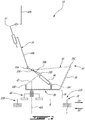
Fig. 1 is a schematic tridimensional view of an aircraft; -
Fig. 2 is a schematic diagram of the structure of a seat which can be used in an aircraft such as shown inFig. 1 , in accordance with an embodiment of the present disclosure; -
Fig. 3A is a schematic tridimensional view of the structure of the seat shown inFig. 2 ; -
Fig. 3B is a schematic side cross-sectional view of the structure of the seat shown inFig. 2 ; -
Fig. 4A is a schematic tridimensional view of first and second engagement members of the seat shown inFig. 3A ; -
Fig. 4B is a top view of the first and second engagement members ofFig. 4A ; -
Fig. 5 is a side view of first and second engagement members of an aircraft such as shown inFig. 1 , according to another embodiment of the present disclosure; and -
Fig. 6 is a side view of first and second engagement members of an aircraft such as shown inFig. 1 , according to yet another embodiment of the present disclosure. - Referring to the drawings and more particularly to
Fig. 1 , an aircraft is shown at 1 and is generally described to illustrate some components for reference purposes in the present disclosure. Theaircraft 1 has a fuselage 2 having a fore end at which a cockpit is located, and an aft end supporting a tail assembly, with the cabin generally located between the cockpit and the tail assembly. The tail assembly comprises a vertical stabilizer 3 with a rudder, and horizontal stabilizers 4 with elevators. The tail assembly has a fuselage-mounted tail, but other configurations may also be used for theaircraft 1, such as cruciform, T-tail, etc.Wings 5 project laterally from the fuselage. Theaircraft 1 has engines 6 supported by thewings 5, although the engines 6 could also be mounted to the fuselage 2. Theaircraft 1 is shown as a jet-engine aircraft, but may also be a propeller aircraft. It is also understood that althoughFig. 1 shows a commercial aircraft, theaircraft 1 may alternately be any other type of aircraft, including, but not limited to, a business aircraft or a private aircraft. - Referring to
Fig. 2 , apassenger seat 10 in accordance with an embodiment is shown. Thepassenger seat 10 is configured to be used, for example, in the cabin of anaircraft 1 such as shown inFig. 1 . Thepassenger seat 10 could alternately be used in any other suitable type of vehicle. Theseat 10 is positioned to be oriented in a direction of theaircraft 1. More particularly, a front of theseat 10 is oriented to face in a first direction D1 of theaircraft 1. The first direction D1 of theaircraft 1 is toward a component at one of the end of theaircraft 1, such as the tail assembly at the rear end of theaircraft 1 or the cockpit at the front end of theaircraft 1. In the depicted embodiment, the first direction D1 of theaircraft 1 is an aft direction, such that the front of theseat 10 is oriented toward the aft end of theaircraft 1 which supports the tail assembly. A second direction D2 of theaircraft 1 is opposite to the first direction D1. Therefore, in the depicted embodiment, the second direction D2 is a forward direction, i.e. a direction toward the fore end of theaircraft 1 at which the cockpit is located. - The
seat 10 is thus aft-facing in the depicted embodiment. Theseat 10 is mounted to the fuselage 2 to position theseat 10 and its occupant facing in the aft, first direction D1 of theaircraft 1. It will therefore be appreciated that the first direction D1 is sometimes referred to herein as the "aft direction D1", and that the second direction D2 is sometimes referred to herein as the "forward direction D2". Theseat 10 may have other orientations. In an alternate embodiment, the front end of theseat 10 is forward facing, such that the first direction D1 of theaircraft 1 is a forward direction toward the fore end of theaircraft 1 at which the cockpit is located, and the second direction D2 is an aft direction toward the aft end of theaircraft 1 which supports the tail assembly. It will also be appreciated that the orientation of theseat 10 may change, such that it is aft-facing in an initial position but displaceable to be forward-facing in a subsequent position, or vice versa. - The
seat 10 includes a fixedseat portion 20, and amoveable seat portion 30 mounted onto the fixedseat portion 20 and displaceable relative thereto. The fixedseat portion 20 anchors theseat 10 to theaircraft 1, and is configured to be connected to a floor structure 7, for example to floor beams interconnected to the fuselage 2. In the embodiment shown, the fixedseat portion 20 includesrails 9 attached to the floor structure 7. The fixedseat portion 20 is fixed in position relative to the floor structure 7. The fixedseat portion 20 has afront end 22A facing toward the tail assembly, and arear end 22B facing toward the cockpit. The fixedseat portion 20 has opposedlateral sides 24 between the front andrear ends centerline 26 of the fixedseat portion 20, and of theseat 10, is defined between thelateral sides 24, and is spaced equally from the lateral sides 24 (seeFig. 3A ). The expressions "front", "forward", "forwardly", "rear", "rearwardly" and other similar positional descriptors when used herein to define the relative location of a component of theseat 10 with respect to other components of theseat 10 refer to the direction of theseat 10 and not of theaircraft 1, where the surface of theseat 10 in contact with the occupant in the taxi, take-off and landing (TTOL) configuration of theseat 10 is considered to be the front of theseat 10, and where the surface of theseat 10 facing away from the occupant is considered to be the rear of theseat 10. It is however understood that depending on the orientation of theseat 10 within theaircraft 1, the front of theseat 10 may be facing toward a front, a rear, a side, etc. of theaircraft 1. - The
seat 10 also includes amoveable seat portion 30 mounted to the fixedseat portion 20 and positioned above the fixedseat portion 20. Themoveable seat portion 30 is displaceable with respect to the fixedseat portion 20. Different configurations of themoveable seat portion 30 are possible to achieve this functionality, and one possible configuration for themoveable seat portion 30 is now described with reference toFig. 2 . - The
moveable seat portion 30 includes aseat pan frame 32 supporting a seat pan, and abackrest frame 34 supporting a backrest, and amoveable connection assembly 36 connected to the fixedseat portion 20, theseat pan frame 32 andbackrest frame 34 connected to themovable connection assembly 36 via a suitable support structure further described below. The mounting of theseat pan frame 32 via thebackrest frame 34 to themoveable connection assembly 36 allows theseat pan frame 32 to pivot from a neutral position and slide between a forwardmost position and a rearwardmost position, as described in greater detail below. - In a particular embodiment, the
seat 10 corresponds to or is similar to the seat described inU.S. provisional application No. 62/608,717 filed December 21, 2017 moveable connection assembly 36 shown here is exemplary only and that any other suitable type ofmoveable connection assembly 36 may alternately be used, including, but not limited to, supports including pivoting attachments, sliding attachments, and fixed attachments. It is also understood that the seat pan and backrest may include any material suitable for providing appropriate support and comfort to the occupant, including, but not limited to, suitable cushioning materials which will not be further described herein. Theseat 10 is selectively configurable between a sitting configuration and a reclined configuration. In a particular embodiment, the sitting configuration corresponds to a TTOL configuration. - The
backrest frame 34 has anupper backrest member 34A supporting the backrest, and alower backrest member 34B extending downwardly from a bottom end of theupper backrest member 34A. In the embodiment shown, the upper andlower backrest members lockable pivot connection 35A, e.g. a selectively lockable revolute joint. In the present disclosure, including claims, the term "revolute joint" is intended to designate a pivot connection between two members which allows relative pivoting motion between the two members about an axis of rotation without allowing relative translation between the two members, i.e. the axis of rotation has a fixed location with respect to each of the two members. Examples of revolute joints include, but are not limited to, a hinge joint, a pin joint, and a folding joint. - The
pivot connection 35A between the upper andlower backrest members lower backrest members lower backrest members pivot connection 35A may include, for example, a lock based on a spring-loaded plunger mechanism; any other suitable mechanism may alternately be used. In the embodiment shown, the upper andlower backrest members lower backrest members - The rear end of the
seat pan frame 32 is pivotally connected to thelower backrest member 34B by apivot connection 35B, which in the embodiment shown is defined by another revolute joint. - Still referring to
Fig. 2 , the backrest also includes aheadrest 37 which is slidingly engaged to a top of theupper backrest member 34A. Theheadrest 37 may include apivotable portion 37A allowing for further adjustment of the position of theheadrest 37. It is understood that the headrest configuration shown is exemplary only, and that any other suitable headrest configuration may alternately be used; alternately, the adjustable headrest may be omitted. - The support structure connecting the
seat pan frame 32 andbackrest frame 34 to themoveable connection assembly 36 includes afront support member 38 defining the frontmost portion (relative to the seat 10) of the support structure. Thefront support member 38 has a top end connected to the front end of theseat pan frame 32 via apivot connection 35C, which in the embodiment shown is defined by a revolute joint. Thefront support member 38 has an opposed bottom end connected to aswivel assembly 40 of themoveable connection assembly 36. Theswivel assembly 40 allows theseat pan frame 32 to rotate about anupright axis 40A of theseat 10. In the embodiment shown, the connection between thefront support member 38 and theswivel assembly 40 is a rigid connection, i.e. allowing no relative motion between theswivel assembly 40 and thefront support member 38. - The support structure connecting the
seat pan frame 32 andbackrest frame 34 to themoveable connection assembly 36 also includes asupport arm 42 for connecting thebackrest frame 34 to theswivel assembly 40. Thesupport arm 42 has one end pivotally connected to thelower backrest member 34B by apivot connection 35D defined at a location spaced from theupper backrest member 34A. In the embodiment shown, thepivot connection 35D between thesupport arm 42 and thelower backrest member 34B is defined by another revolute joint. A lower end of thesupport arm 42 is connected to theswivel assembly 40 via anotherpivot connection 35E, which in the embodiment shown is also defined as a fixed pivot or revolute joint. Thepivot connection 35E between thesupport arm 42 and theswivel assembly 40 is located aft of thepivot connection 35C between the front end of theseat pan frame 32 and thefront support member 38 and, in the embodiment shown, is located at the rear of theswivel assembly 40. Thepivot connection 35C between the front end of theseat pan frame 32 and thefront support member 38 is upwardly offset with respect to thepivot connection 35E between thesupport arm 42 and theswivel assembly 40. - Still referring to
Fig. 2 , the support structure connecting theseat pan frame 32 andbackrest frame 36 to themoveable connection assembly 36 also includes a biasing and/or damping member, for example agas spring 44 or any suitable type of linear actuator located under theseat pan frame 32. In a particular embodiment, having thegas spring 44 located under theseat pan frame 32 as opposed to behind thebackrest frame 34 allows for the backrest to have a reduced thickness, which may provide increased free space for the occupant(s) of the adjacent seat(s). - In the embodiment shown, the
gas spring 44 has one end pivotally connected to thelower backrest member 34B and to the rear end of theseat pan frame 32 at thepivot connection 35B between thelower backrest member 34B and the rear end of theseat pan frame 32. The opposed end of thegas spring 44 is pivotally connected to theswivel assembly 40 by apivot connection 35F, which in the embodiment shown is also defined as a fixed pivot or revolute joint. Thepivot connection 35F between thegas spring 44 and theswivel assembly 40 is located between thepivot connections swivel assembly 40 with the front end of theseat pan frame 32 and with thesupport arm 42. - In the embodiment shown, the
gas spring 44 is connected toward the front of theswivel assembly 40, so that its connection with theswivel assembly 40 remains forward of its connection with thelower backrest member 34B andseat pan frame 32 throughout the motion of thebackrest frame 34 and theseat pan frame 32 between the sitting and reclined configurations. Thepivot connections lower backrest member 34B remain aft of thepivot connection 35F between thegas spring 44 and theswivel assembly 40 as thebackrest frame 34 andseat pan frame 32 move between the sitting configuration and the reclined configuration. - Still referring to
Fig. 2 , themoveable connection assembly 36 also includes a slidingassembly 46. A bottom of theswivel assembly 40 is mounted to the slidingassembly 46. The slidingassembly 46 is mounted to therails 9 of the fixedseat portion 20 to connect themoveable connection assembly 36 to the fixedseat portion 20. The slidingassembly 46 allows theseat pan frame 32, and thus themoveable seat portion 30, to slide along therails 9 and thereby translate in the aft and forward directions D1,D2 of theaircraft 1. - The architecture of the aft-facing
seat 10 shown inFig. 2 supports theswivel assembly 40 near the rear of theseat 10. The connection between the swivel and slidingassemblies swivel axis 40A, is aligned with a rear portion of theseat pan frame 32 . Consequently, if a dynamic aircraft event during TTOL causes theseat 10 and its occupant to pitch in the forward direction D2 of theaircraft 1, i.e. in a direction pushing thebackrest frame 34 toward the rear of theseat 10 and the front end of theseat pan frame 32 upwardly, the forces caused by the weight of the occupant pushing against thebackrest frame 34, and the moment created by that force transmitted via thefront support member 38 and themovable connection assembly 36, may be sufficiently large to damage the connection between the swivel and slidingassemblies - To better counteract the moment generated during the dynamic aircraft event, the connection between the fixed and
moveable seat portions Figs. 3A and 3B , the fixedseat portion 20 has afirst engagement member 50 and themoveable seat portion 30 has asecond engagement member 60, both of which are now described in greater detail. The first andsecond engagement members first engagement member 50 is fixedly attached to the fixedseat portion 20, and thesecond engagement member 60 is fixedly attached to themoveable seat portion 30. - The
first engagement member 50 extends upwardly from thefront end 22A of the fixedseat portion 20 at thecenterline 26. Thefirst engagement member 50 terminates at an upperfirst engagement end 52. Thefirst engagement member 50 is fixed in position because it is mounted to the fixedset portion 20. Thesecond engagement member 60 extends downwardly from the front of themoveable seat portion 30 to asecond engagement end 62 at a lower, distal end of thesecond engagement member 60. Thesecond engagement member 60 and thesecond engagement end 62 are displaceable with themoveable seat portion 30. In the depicted embodiment, thesecond engagement member 60 is mounted to the front of theswivel assembly 40. In the depicted embodiment, thesecond engagement member 60 is displaceable in the aft and forward directions D1,D2, and in a swivel or yaw direction about theupright axis 40A, together with themovable seat portion 30. - When the first and
second engagement members moveable seat portions Figs. 3A and 3B , thesecond engagement end 62 of the movable seatportion engagement member 60 is positioned underneath thefirst engagement end 52 of the fixed seatportion engagement member 50. In this engagement position, thefirst engagement end 52 overlaps or overlies thesecond engagement end 62. In this engagement position, themoveable seat portion 30 is prevented from pitching in the forward direction D2 of theaircraft 1 during a dynamic aircraft event, because thesecond engagement end 62 would abut against thefirst engagement end 52 such that thefirst engagement end 52 would block further pitch displacement of thesecond engagement end 62. - It will therefore be appreciated that the first and
second engagement members moveable seat portions moveable seat portion 30 relative to the fixedseat portion 20 in normal flight conditions. In theseat 10 shown inFigs. 3A and 3B , the first andsecond engagement members assemblies seat 10 is in the TTOL position, thereby helping to reduce the likelihood of a failure in either one of these components. - The first and
second engagement members second engagement members first engagement end 52 of the fixed seatportion engagement member 50 has a firsthorizontal segment 54 which extends away from afirst upright segment 56 of thefirst engagement member 50 in the aft direction D1 of theaircraft 1. Thesecond engagement end 62 of the movable seatportion engagement member 60 has a secondhorizontal segment 64 which extends away from asecond upright segment 66 of thesecond engagement member 60 in the forward direction D2 of theaircraft 1. The secondhorizontal segment 64 is positioned underneath the firsthorizontal segment 54 in the engagement position. - Another possible shape for the first and second engagement members 150,160 is shown in
Fig. 5 . The first and second engagement members 150,160 form complementary engageable female and male components. Thefirst upright segment 156 of thefirst engagement member 150 of the fixed seat portion has anopening 158 delimited by asupport ridge 159 above theopening 158 at thefirst engagement end 152. In the depicted embodiment, thefirst engagement member 150 does not have a transverse or horizontal component. Thesecond upright segment 166 is fixedly attached to a component of themoveable seat portion 30 and does not move with respect to themoveable seat portion 30. The secondhorizontal segment 164 of thesecond engagement end 162 of the movable seatportion engagement member 160 extends away from thesecond upright segment 166 in the forward direction D2 of theaircraft 1. To place the first and second engagement members 150,160 in the engagement position, the secondhorizontal segment 164 is positioned through theopening 158 and underneath thesupport ridge 159. Displacing themoveable seat portion 30 by translating it in the aft direction D1 of theaircraft 1 with respect to the fixedseat portion 20 will disengage the first and second engagement members 150,160 from the engagement position. - Yet another possible shape for the first and second engagement members 250,260 is shown in
Fig. 6 . The first and second engagement ends 252,262 have complementary "mushroom" shapes, for example similar to a hitch engagement for a road vehicle. More particularly, thesecond engagement end 262 of the movable seatportion engagement member 260 has a mushroom-shapedcap 264 defining an internal cavity, and anopening 265 in a side of thecap 264. Thefirst engagement end 252 of the fixed seatportion engagement member 250 has a mushroom-shapedprotrusion 254. To place the first and second engagement members 250,260 in the engagement position, thecap 264 is displaced toward theprotrusion 254 such that theprotrusion 254 slides through theopening 265 in thecap 264 and fits within the cavity of thecap 264. - It will therefore be appreciated that the present disclosure includes many possible shapes for the first and
second engagement members 50,60,150,160,250,260 which allow them to engage one another at the front and center of theseat 10 to prevent theseat 10 from pitching in the forward direction D2 of theaircraft 1 during a dynamic aircraft event. In yet another embodiment, the first andsecond engagement members 50,60,150,160,250,260 are positioned in the engagement position using interlocking components or mechanical devices. - Returning to
Figs. 3A and 3B , the first andsecond engagement members moveable seat portion 30 to be displaced relative to the fixedseat portion 20 to place the first andsecond engagement members second engagement members Fig. 3B , agap 48 is defined between the first andsecond engagement members gap 48 has a vertical dimension between the overlapping first and second engagement ends 52,62, and a horizontal dimension. The movement of themovable seat portion 30 of the aft-facingseat 10 will now be described relative to the aircraft directions. Accordingly, it is understood that the forward direction D2 of theaircraft 1 corresponds to the aft direction relative to the seat structure, and that the aft direction D1 of theaircraft 1 corresponds to the forward direction relative to the seat structure. - To place the first and
second engagement members moveable seat portion 30 may be slid or translated in the forward direction D2 of theaircraft 1 to place the aft-facingseat 10 it its forwardmost position relative to the aircraft. This movement of themoveable seat portion 30 positions thesecond engagement end 62 of the movable seatportion engagement member 60 under thefirst engagement end 52 of the fixed seatportion engagement member 50 in the engagement position. This is shown inFigs. 3A and 3B , where adisplacement mechanism 46A of the slidingassembly 46 is positioned on therails 9 at its forwardmost position relative to the aircraft. In this position, theseat 10 cannot translate further during a dynamic aircraft event. In the depicted embodiment, moving theseat 10 forwards relative to theaircraft 1 will automatically place the first andsecond engagement members - Similarly, displacing the
moveable seat portion 30 in the aft direction D1 of theaircraft 1 will disengage the first andsecond engagement members Figs. 3A and 3B , causing thedisplacement mechanism 46A of the slidingassembly 46 to slide along therails 9 of the fixedseat portion 20 in the aft direction D1 of theaircraft 1 will move thesecond engagement end 62 away from overlapping thefirst engagement end 52, and thereby disengage thefirst engagement member 50 from thesecond engagement member 60. Therefore, in the depicted embodiment, no manual manipulation of the first andsecond engagement members - The first and
second engagement members moveable seat portion 30 about theupright axis 40A. Referring toFigs. 4A and 4B , in a particular embodiment both the first and second engagement ends 52,62 have adistal edge distal edge 53 of thefirst engagement end 52 faces thesecond upright segment 66 of thesecond engagement member 60, and thedistal edge 63 of thesecond engagement end 62 faces thefirst upright segment 56 of thefirst engagement member 50. Each of the first and secondupright segments engagement surface distal edge gap 48 in the engagement position. The distal edges 53,63 defining a distal edge shape that is similar to a shape of the engagement surfaces 55,65 (seeFig. 4B ). In the depicted embodiment, the distal edge and engagement surface shapes are curves, such that the curvature of thedistal edges moveable seat portion 30 may therefore be swiveled about theupright axis 40 along aswivel arc 49 without contacting the first andsecond engagement members second engagement members swivel assembly 40 to rotate themoveable seat portion 30 about theupright axis 40A, which will move thesecond engagement end 62 from its overlapping position above thefirst engagement end 52, and thereby disengage thefirst engagement member 50 from thesecond engagement member 60. The occupant is able to swivel theseat 10 to disengage from the engagement position even when theseat 10 is in its rearwardmost position. - Alternately, the
distal edges - It will therefore be appreciated that the first and
second engagement members moveable seat portion 30 relative to the fixedseat portion 20. Indeed, when in the engagement position, the first andsecond engagement members moveable seat portion 30 in the aft direction D1 of theaircraft 1, and a yaw or swivel direction about theupright axis 40A. The first andsecond engagement members moveable seat portion 30, and act to arrest displacement of themoveable seat portion 30 only in the pitch direction when in the engagement position, thereby allowing theseat 10 and its occupant to preserve most of the mobility of theseat 10. - Referring to
Fig. 3A and 3B , there is also disclosed a method of positioning the aft-facingpassenger seat 10. The method includes: displacing themoveable seat portion 30 above and with respect to the fixedseat portion 20 to engage thefirst engagement member 50 with thesecond engagement member 60 along a front 22A of the fixed seat portion 20 a centre of the fixedseat portion 20. Thefirst engagement member 50 at least partially overlies thesecond engagement member 60 to prevent themoveable seat portion 30 from pitching in the forward direction D2 of theaircraft 1. - The above description is meant to be exemplary only, and one skilled in the art will recognize that changes may be made to the embodiments described without departing from the scope of the invention which is defined by appended claims.
Claims (10)
- A passenger seat (10) for an aircraft (1), the seat (10) comprising:a fixed seat portion (20) configured to be connected to a floor of the aircraft (1) to position a front (22A) of the fixed seat portion (20) facing toward a first direction of the aircraft (1), the fixed seat portion (20) having a centerline (26) spaced equally from opposed lateral sides (24) of the fixed seat portion (20), and a first engagement member (50) extending upwardly from the front (22A) of the fixed seat portion (20) at the centerline (26) to a first engagement end (52); anda moveable seat portion (30), including a seat pan frame (32) supporting a seat pan, and a backrest frame (34) supporting a backrest, mounted onto the fixed seat portion (20) and being displaceable relative thereto, the moveable seat portion (30) having a second engagement member (60) extending downwardly from a front of the moveable seat portion (30) to a second engagement end (62), the second engagement member (60) being displaceable with the moveable seat portion (30) to position the second engagement end (62) under the first engagement end (52) of the first engagement member (50) in an engagement position such that the overlapping first and second engagement ends prevent the moveable seat portion (30) from pitching in a second direction of the aircraft (1) opposite to the first direction,characterized in that the moveable seat portion (30) is displaceable relative to the fixed seat portion (20) in the first and second directions through a sliding assembly (46) mounted to rails (9) of the fixed seat portion (30), and in a yaw direction about an upright axis (40A) of the seat (10), through a swivel assembly (40).
- The passenger seat (10) as defined in claim 1, wherein the first engagement member (50) is spaced apart from the second engagement member (60) in the engagement position to define a gap (48) between the first and second engagement members.
- The passenger seat (10) as defined in claim 1 or 2, wherein at least one of the first and second engagement ends has a distal edge (53,63) and at least one of the first and second engagement members has an upright segment with an engagement surface (55,65) facing the distal edge (53,63) and spaced apart therefrom in the engagement position, the distal edge (53,63) defining a distal edge shape and the engagement surface (55,65) having an engagement surface shape being complementary to the distal edge shape.
- The passenger seat (10) as defined in any one of claims 1 to 3, wherein the first engagement end (52) has a first horizontal segment (54) and the second engagement end (62) has a second horizontal segment (64), the second horizontal segment (64) being positioned under the first horizontal segment (54) in the engagement position.
- The passenger seat (10) as defined in any one of claims 1 to 4, wherein the first engagement member (50) is fixedly attached to the fixed seat portion (20), and the second engagement member (60) is fixedly attached to the moveable seat portion (30).
- The passenger seat (10) as defined in any one of claims 1 to 5, wherein the second engagement end (62) is positioned under the first engagement end (52) in the engagement position upon the moveable seat portion (30) being in a forwardmost position relative to the aircraft (1).
- A method of positioning a passenger seat (10) of an aircraft (1), the method comprising displacing a moveable seat portion (30) above and with respect to a fixed seat portion (20) to engage a first engagement member (50) of the fixed seat portion (20) with a second engagement member (60) of the moveable seat portion (30) along a front (22A) of the fixed seat portion (20) and a centre of the fixed seat portion (20), the front (22A) of the fixed seat portion (20) facing toward a first direction of the aircraft (1), the first engagement member (50) at least partially overlying the second engagement member (60) to prevent the moveable seat portion (30) from pitching in a second direction of the aircraft (1) opposite to the first direction,
characterized in that displacing the moveable seat portion (30) includes translating the moveable seat portion (30) with respect to the fixed seat portion (20) in the second direction of the aircraft (1) to a forwardmost position of the moveable seat portion (30) relative to the aircraft (1) to at least partially overlie the second engagement member (60) with the first engagement member (50). - The method as defined in claim 7, wherein displacing the moveable seat portion (30) includes translating the moveable seat portion (30) in the first direction of the aircraft (1) to disengage the first engagement member (50) from the second engagement member (60).
- The method as defined in claim 7, wherein displacing the moveable seat portion (30) includes rotating the moveable seat portion (30) about an upright axis (40A) of the seat (10) when in the forwardmost position to disengage the first engagement member (50) from the second engagement member (60).
- The method as defined in any one of claims 7 to 9, further comprising arresting displacement of the moveable seat portion (30) in a pitch direction with the first and second engagement members.
Applications Claiming Priority (1)
| Application Number | Priority Date | Filing Date | Title |
|---|---|---|---|
| US201862639202P | 2018-03-06 | 2018-03-06 |
Publications (2)
| Publication Number | Publication Date |
|---|---|
| EP3536614A1 EP3536614A1 (en) | 2019-09-11 |
| EP3536614B1 true EP3536614B1 (en) | 2020-12-09 |
Family
ID=65717856
Family Applications (1)
| Application Number | Title | Priority Date | Filing Date |
|---|---|---|---|
| EP19160964.3A Active EP3536614B1 (en) | 2018-03-06 | 2019-03-06 | Passenger seat for aircraft |
Country Status (4)
| Country | Link |
|---|---|
| US (1) | US10822091B2 (en) |
| EP (1) | EP3536614B1 (en) |
| CN (1) | CN110228592B (en) |
| CA (1) | CA3036019A1 (en) |
Families Citing this family (1)
| Publication number | Priority date | Publication date | Assignee | Title |
|---|---|---|---|---|
| WO2019119126A1 (en) * | 2017-12-21 | 2019-06-27 | Bombardier Inc. | Passenger seat with support structure including offset struts |
Family Cites Families (37)
| Publication number | Priority date | Publication date | Assignee | Title |
|---|---|---|---|---|
| FR1543275A (en) * | 1967-07-31 | 1968-10-25 | Peugeot | New, energy-absorbing arrangement of a seat on a vehicle |
| US4911381A (en) * | 1987-12-28 | 1990-03-27 | Simula, Inc. | Energy-absorbing leg assembly for aircraft passenger seats |
| DE4206789C1 (en) * | 1992-03-04 | 1993-02-11 | Mercedes-Benz Aktiengesellschaft, 7000 Stuttgart, De | Seat frame and cushion squab in bus - are adjustably joined to seat back, pivot round rear axis on seat subframe and include deformation element at front |
| DE19513777B4 (en) | 1994-04-13 | 2004-04-15 | Pitencel, Héctor Manuel | headrest |
| IL109446A (en) * | 1994-04-26 | 1999-09-22 | Israel Aircraft Ind Ltd | Vehicle seat |
| US5568960A (en) | 1995-09-15 | 1996-10-29 | Aircraft Modular Products, Inc. | Aircraft passenger seat swivel assembly |
| FR2798629B1 (en) * | 1999-09-16 | 2001-11-09 | Faure Bertrand Equipements Sa | SEAT OF A MOTOR VEHICLE SEAT COMPRISING AN ANTI-SUBMARINE CROSSING |
| DE10012973B4 (en) | 2000-03-16 | 2004-02-26 | Daimlerchrysler Ag | Headrest for a vehicle seat |
| DE10019484A1 (en) * | 2000-04-19 | 2001-10-31 | Recaro Aircraft Seating Gmbh | Vehicle seat, in particular passenger seat |
| ATE309110T1 (en) * | 2001-08-09 | 2005-11-15 | Virgin Atlantic Airways Ltd | A SEATING ARRANGEMENT AND A PASSENGER ACCOMMODATION UNIT FOR A VEHICLE |
| EP2272712A1 (en) * | 2004-10-19 | 2011-01-12 | Indiana Mills & Manufacturing, Inc. | Vehicle safety seat |
| JP4177390B2 (en) * | 2006-05-22 | 2008-11-05 | 本田技研工業株式会社 | Vehicle seat |
| US8292221B2 (en) | 2007-03-27 | 2012-10-23 | Ami Industries, Inc. | Aircraft equipment support |
| GB0706775D0 (en) * | 2007-04-05 | 2007-05-16 | Premium Aircraft Interiors Uk | Aircraft seat |
| FR2917344B1 (en) | 2007-06-15 | 2009-08-21 | Airbus France Sas | MULTIMODAL HEADREST FOR VEHICLE SEAT |
| US8376458B2 (en) * | 2009-11-02 | 2013-02-19 | B/E Aerospace, Inc. | Seat pan cam follower with drop down mechanism |
| US8827365B2 (en) * | 2010-02-10 | 2014-09-09 | Zodiac Seats Us Llc | Passenger seat |
| CA2789272A1 (en) * | 2010-02-10 | 2011-08-18 | Weber Aircraft Llc | Passenger seat |
| US8641140B2 (en) * | 2010-03-17 | 2014-02-04 | Richard Swierczewski | Vehicle safety seat |
| CA2795824A1 (en) * | 2010-05-03 | 2011-11-10 | Weber Aircraft Llc | Seat support assembly |
| EP2718184B1 (en) | 2011-06-10 | 2016-08-31 | Zodiac Seats US LLC | Passenger seat assembly |
| EP2729365B1 (en) * | 2011-07-06 | 2016-11-30 | Zodiac Seats US LLC | Seat pan assembly |
| EP2981190B1 (en) * | 2013-04-05 | 2021-11-17 | St Engineering Aerospace Ltd. | Passenger seat for an aircraft |
| DE102013012284A1 (en) * | 2013-08-14 | 2015-02-19 | Volkswagen Aktiengesellschaft | Easy-entry adjustment mechanism for dive-down vehicle seats or seat systems |
| US10005558B2 (en) * | 2014-03-28 | 2018-06-26 | Zodiac Seats France | Track fitting for aircraft seats |
| EP3126236B1 (en) * | 2014-04-02 | 2021-06-09 | B/E Aerospace, Inc. | Cradle recline mechanism for fixed-shell aircraft seat |
| US20170021930A1 (en) * | 2014-04-02 | 2017-01-26 | B/E Aerospace, Inc. | Cradle recline mechanism for aircraft passenger seat |
| US10322808B2 (en) * | 2014-09-04 | 2019-06-18 | Safran Seats Usa Llc | Expandable seat leg attachment fixture |
| GB2530556A (en) * | 2014-09-26 | 2016-03-30 | Bombardier Inc | Aircraft seat |
| US9764844B2 (en) * | 2015-04-13 | 2017-09-19 | Encore Seats, Inc. | Aircraft seating assembly |
| GB2539913B (en) * | 2015-06-30 | 2019-10-02 | British Airways Plc | Aircraft passenger seat mechanism |
| US9840332B2 (en) * | 2015-10-15 | 2017-12-12 | The Boeing Company | Deployable door-mounted seat |
| US10632865B2 (en) * | 2017-11-02 | 2020-04-28 | Ford Global Technologies, Llc | Drive cable for a seating assembly |
| US10604032B2 (en) * | 2017-11-02 | 2020-03-31 | Ford Global Technologies, Llc | Translatable seating assembly |
| US10569669B2 (en) * | 2018-02-27 | 2020-02-25 | Ford Global Technologies, Llc | In-floor track system |
| US20190308579A1 (en) * | 2018-04-06 | 2019-10-10 | Astronics Advanced Electronic Systems Corp. | Seat Sensing and Reporting Apparatus |
| DE102018109995A1 (en) * | 2018-04-25 | 2019-10-31 | Airbus Operations Gmbh | Fastening system for fastening installation elements in a cabin of a vehicle |
-
2019
- 2019-03-06 US US16/293,740 patent/US10822091B2/en active Active
- 2019-03-06 EP EP19160964.3A patent/EP3536614B1/en active Active
- 2019-03-06 CA CA3036019A patent/CA3036019A1/en active Pending
- 2019-03-06 CN CN201910167339.3A patent/CN110228592B/en active Active
Non-Patent Citations (1)
| Title |
|---|
| None * |
Also Published As
| Publication number | Publication date |
|---|---|
| CN110228592A (en) | 2019-09-13 |
| CA3036019A1 (en) | 2019-09-06 |
| EP3536614A1 (en) | 2019-09-11 |
| US20190276152A1 (en) | 2019-09-12 |
| CN110228592B (en) | 2022-11-18 |
| US10822091B2 (en) | 2020-11-03 |
Similar Documents
| Publication | Publication Date | Title |
|---|---|---|
| EP2794396B1 (en) | Aircraft passenger seat and seat swivel assembly | |
| US20220048627A1 (en) | Reclinable passenger seat | |
| US20190233119A1 (en) | Work-and-Dine Aircraft Seat with Tilt and Shift Articulation | |
| EP3536614B1 (en) | Passenger seat for aircraft | |
| US11447254B2 (en) | Passenger seat with support structure including offset struts | |
| EP3728032B1 (en) | Passenger seat with support structure defining empty space | |
| EP3795473B1 (en) | Aircraft with an aircraft divan | |
| EP4163150A1 (en) | Reclinable seat with multiple configurations | |
| US11254434B2 (en) | Headrest for a seat | |
| EP4337532A1 (en) | Seat with tray table |
Legal Events
| Date | Code | Title | Description |
|---|---|---|---|
| PUAI | Public reference made under article 153(3) epc to a published international application that has entered the european phase |
Free format text: ORIGINAL CODE: 0009012 |
|
| STAA | Information on the status of an ep patent application or granted ep patent |
Free format text: STATUS: THE APPLICATION HAS BEEN PUBLISHED |
|
| AK | Designated contracting states |
Kind code of ref document: A1 Designated state(s): AL AT BE BG CH CY CZ DE DK EE ES FI FR GB GR HR HU IE IS IT LI LT LU LV MC MK MT NL NO PL PT RO RS SE SI SK SM TR |
|
| AX | Request for extension of the european patent |
Extension state: BA ME |
|
| STAA | Information on the status of an ep patent application or granted ep patent |
Free format text: STATUS: REQUEST FOR EXAMINATION WAS MADE |
|
| 17P | Request for examination filed |
Effective date: 20200311 |
|
| RBV | Designated contracting states (corrected) |
Designated state(s): AL AT BE BG CH CY CZ DE DK EE ES FI FR GB GR HR HU IE IS IT LI LT LU LV MC MK MT NL NO PL PT RO RS SE SI SK SM TR |
|
| GRAP | Despatch of communication of intention to grant a patent |
Free format text: ORIGINAL CODE: EPIDOSNIGR1 |
|
| STAA | Information on the status of an ep patent application or granted ep patent |
Free format text: STATUS: GRANT OF PATENT IS INTENDED |
|
| RIC1 | Information provided on ipc code assigned before grant |
Ipc: B60N 2/42 20060101ALI20200526BHEP Ipc: B64D 11/06 20060101AFI20200526BHEP Ipc: B60N 2/427 20060101ALI20200526BHEP |
|
| INTG | Intention to grant announced |
Effective date: 20200630 |
|
| GRAS | Grant fee paid |
Free format text: ORIGINAL CODE: EPIDOSNIGR3 |
|
| GRAA | (expected) grant |
Free format text: ORIGINAL CODE: 0009210 |
|
| STAA | Information on the status of an ep patent application or granted ep patent |
Free format text: STATUS: THE PATENT HAS BEEN GRANTED |
|
| AK | Designated contracting states |
Kind code of ref document: B1 Designated state(s): AL AT BE BG CH CY CZ DE DK EE ES FI FR GB GR HR HU IE IS IT LI LT LU LV MC MK MT NL NO PL PT RO RS SE SI SK SM TR |
|
| REG | Reference to a national code |
Ref country code: GB Ref legal event code: FG4D |
|
| REG | Reference to a national code |
Ref country code: CH Ref legal event code: EP Ref country code: AT Ref legal event code: REF Ref document number: 1343186 Country of ref document: AT Kind code of ref document: T Effective date: 20201215 |
|
| REG | Reference to a national code |
Ref country code: DE Ref legal event code: R096 Ref document number: 602019001609 Country of ref document: DE |
|
| REG | Reference to a national code |
Ref country code: IE Ref legal event code: FG4D |
|
| PG25 | Lapsed in a contracting state [announced via postgrant information from national office to epo] |
Ref country code: FI Free format text: LAPSE BECAUSE OF FAILURE TO SUBMIT A TRANSLATION OF THE DESCRIPTION OR TO PAY THE FEE WITHIN THE PRESCRIBED TIME-LIMIT Effective date: 20201209 Ref country code: RS Free format text: LAPSE BECAUSE OF FAILURE TO SUBMIT A TRANSLATION OF THE DESCRIPTION OR TO PAY THE FEE WITHIN THE PRESCRIBED TIME-LIMIT Effective date: 20201209 Ref country code: GR Free format text: LAPSE BECAUSE OF FAILURE TO SUBMIT A TRANSLATION OF THE DESCRIPTION OR TO PAY THE FEE WITHIN THE PRESCRIBED TIME-LIMIT Effective date: 20210310 Ref country code: NO Free format text: LAPSE BECAUSE OF FAILURE TO SUBMIT A TRANSLATION OF THE DESCRIPTION OR TO PAY THE FEE WITHIN THE PRESCRIBED TIME-LIMIT Effective date: 20210309 |
|
| REG | Reference to a national code |
Ref country code: AT Ref legal event code: MK05 Ref document number: 1343186 Country of ref document: AT Kind code of ref document: T Effective date: 20201209 |
|
| PG25 | Lapsed in a contracting state [announced via postgrant information from national office to epo] |
Ref country code: SE Free format text: LAPSE BECAUSE OF FAILURE TO SUBMIT A TRANSLATION OF THE DESCRIPTION OR TO PAY THE FEE WITHIN THE PRESCRIBED TIME-LIMIT Effective date: 20201209 Ref country code: LV Free format text: LAPSE BECAUSE OF FAILURE TO SUBMIT A TRANSLATION OF THE DESCRIPTION OR TO PAY THE FEE WITHIN THE PRESCRIBED TIME-LIMIT Effective date: 20201209 Ref country code: BG Free format text: LAPSE BECAUSE OF FAILURE TO SUBMIT A TRANSLATION OF THE DESCRIPTION OR TO PAY THE FEE WITHIN THE PRESCRIBED TIME-LIMIT Effective date: 20210309 |
|
| REG | Reference to a national code |
Ref country code: NL Ref legal event code: MP Effective date: 20201209 |
|
| PG25 | Lapsed in a contracting state [announced via postgrant information from national office to epo] |
Ref country code: HR Free format text: LAPSE BECAUSE OF FAILURE TO SUBMIT A TRANSLATION OF THE DESCRIPTION OR TO PAY THE FEE WITHIN THE PRESCRIBED TIME-LIMIT Effective date: 20201209 Ref country code: NL Free format text: LAPSE BECAUSE OF FAILURE TO SUBMIT A TRANSLATION OF THE DESCRIPTION OR TO PAY THE FEE WITHIN THE PRESCRIBED TIME-LIMIT Effective date: 20201209 |
|
| REG | Reference to a national code |
Ref country code: LT Ref legal event code: MG9D |
|
| PG25 | Lapsed in a contracting state [announced via postgrant information from national office to epo] |
Ref country code: LT Free format text: LAPSE BECAUSE OF FAILURE TO SUBMIT A TRANSLATION OF THE DESCRIPTION OR TO PAY THE FEE WITHIN THE PRESCRIBED TIME-LIMIT Effective date: 20201209 Ref country code: PT Free format text: LAPSE BECAUSE OF FAILURE TO SUBMIT A TRANSLATION OF THE DESCRIPTION OR TO PAY THE FEE WITHIN THE PRESCRIBED TIME-LIMIT Effective date: 20210409 Ref country code: RO Free format text: LAPSE BECAUSE OF FAILURE TO SUBMIT A TRANSLATION OF THE DESCRIPTION OR TO PAY THE FEE WITHIN THE PRESCRIBED TIME-LIMIT Effective date: 20201209 Ref country code: EE Free format text: LAPSE BECAUSE OF FAILURE TO SUBMIT A TRANSLATION OF THE DESCRIPTION OR TO PAY THE FEE WITHIN THE PRESCRIBED TIME-LIMIT Effective date: 20201209 Ref country code: SM Free format text: LAPSE BECAUSE OF FAILURE TO SUBMIT A TRANSLATION OF THE DESCRIPTION OR TO PAY THE FEE WITHIN THE PRESCRIBED TIME-LIMIT Effective date: 20201209 Ref country code: SK Free format text: LAPSE BECAUSE OF FAILURE TO SUBMIT A TRANSLATION OF THE DESCRIPTION OR TO PAY THE FEE WITHIN THE PRESCRIBED TIME-LIMIT Effective date: 20201209 Ref country code: CZ Free format text: LAPSE BECAUSE OF FAILURE TO SUBMIT A TRANSLATION OF THE DESCRIPTION OR TO PAY THE FEE WITHIN THE PRESCRIBED TIME-LIMIT Effective date: 20201209 |
|
| PG25 | Lapsed in a contracting state [announced via postgrant information from national office to epo] |
Ref country code: AT Free format text: LAPSE BECAUSE OF FAILURE TO SUBMIT A TRANSLATION OF THE DESCRIPTION OR TO PAY THE FEE WITHIN THE PRESCRIBED TIME-LIMIT Effective date: 20201209 Ref country code: PL Free format text: LAPSE BECAUSE OF FAILURE TO SUBMIT A TRANSLATION OF THE DESCRIPTION OR TO PAY THE FEE WITHIN THE PRESCRIBED TIME-LIMIT Effective date: 20201209 |
|
| REG | Reference to a national code |
Ref country code: DE Ref legal event code: R097 Ref document number: 602019001609 Country of ref document: DE |
|
| PG25 | Lapsed in a contracting state [announced via postgrant information from national office to epo] |
Ref country code: IS Free format text: LAPSE BECAUSE OF FAILURE TO SUBMIT A TRANSLATION OF THE DESCRIPTION OR TO PAY THE FEE WITHIN THE PRESCRIBED TIME-LIMIT Effective date: 20210409 |
|
| PLBE | No opposition filed within time limit |
Free format text: ORIGINAL CODE: 0009261 |
|
| STAA | Information on the status of an ep patent application or granted ep patent |
Free format text: STATUS: NO OPPOSITION FILED WITHIN TIME LIMIT |
|
| PG25 | Lapsed in a contracting state [announced via postgrant information from national office to epo] |
Ref country code: AL Free format text: LAPSE BECAUSE OF FAILURE TO SUBMIT A TRANSLATION OF THE DESCRIPTION OR TO PAY THE FEE WITHIN THE PRESCRIBED TIME-LIMIT Effective date: 20201209 Ref country code: MC Free format text: LAPSE BECAUSE OF FAILURE TO SUBMIT A TRANSLATION OF THE DESCRIPTION OR TO PAY THE FEE WITHIN THE PRESCRIBED TIME-LIMIT Effective date: 20201209 Ref country code: IT Free format text: LAPSE BECAUSE OF FAILURE TO SUBMIT A TRANSLATION OF THE DESCRIPTION OR TO PAY THE FEE WITHIN THE PRESCRIBED TIME-LIMIT Effective date: 20201209 |
|
| 26N | No opposition filed |
Effective date: 20210910 |
|
| PG25 | Lapsed in a contracting state [announced via postgrant information from national office to epo] |
Ref country code: DK Free format text: LAPSE BECAUSE OF FAILURE TO SUBMIT A TRANSLATION OF THE DESCRIPTION OR TO PAY THE FEE WITHIN THE PRESCRIBED TIME-LIMIT Effective date: 20201209 Ref country code: SI Free format text: LAPSE BECAUSE OF FAILURE TO SUBMIT A TRANSLATION OF THE DESCRIPTION OR TO PAY THE FEE WITHIN THE PRESCRIBED TIME-LIMIT Effective date: 20201209 |
|
| REG | Reference to a national code |
Ref country code: BE Ref legal event code: MM Effective date: 20210331 |
|
| PG25 | Lapsed in a contracting state [announced via postgrant information from national office to epo] |
Ref country code: LU Free format text: LAPSE BECAUSE OF NON-PAYMENT OF DUE FEES Effective date: 20210306 Ref country code: IE Free format text: LAPSE BECAUSE OF NON-PAYMENT OF DUE FEES Effective date: 20210306 Ref country code: ES Free format text: LAPSE BECAUSE OF FAILURE TO SUBMIT A TRANSLATION OF THE DESCRIPTION OR TO PAY THE FEE WITHIN THE PRESCRIBED TIME-LIMIT Effective date: 20201209 |
|
| PG25 | Lapsed in a contracting state [announced via postgrant information from national office to epo] |
Ref country code: IS Free format text: LAPSE BECAUSE OF FAILURE TO SUBMIT A TRANSLATION OF THE DESCRIPTION OR TO PAY THE FEE WITHIN THE PRESCRIBED TIME-LIMIT Effective date: 20210409 |
|
| PG25 | Lapsed in a contracting state [announced via postgrant information from national office to epo] |
Ref country code: BE Free format text: LAPSE BECAUSE OF NON-PAYMENT OF DUE FEES Effective date: 20210331 |
|
| REG | Reference to a national code |
Ref country code: CH Ref legal event code: PL |
|
| PG25 | Lapsed in a contracting state [announced via postgrant information from national office to epo] |
Ref country code: LI Free format text: LAPSE BECAUSE OF NON-PAYMENT OF DUE FEES Effective date: 20220331 Ref country code: CH Free format text: LAPSE BECAUSE OF NON-PAYMENT OF DUE FEES Effective date: 20220331 |
|
| PGFP | Annual fee paid to national office [announced via postgrant information from national office to epo] |
Ref country code: FR Payment date: 20230327 Year of fee payment: 5 |
|
| PGFP | Annual fee paid to national office [announced via postgrant information from national office to epo] |
Ref country code: GB Payment date: 20230322 Year of fee payment: 5 Ref country code: DE Payment date: 20230321 Year of fee payment: 5 |
|
| PG25 | Lapsed in a contracting state [announced via postgrant information from national office to epo] |
Ref country code: CY Free format text: LAPSE BECAUSE OF FAILURE TO SUBMIT A TRANSLATION OF THE DESCRIPTION OR TO PAY THE FEE WITHIN THE PRESCRIBED TIME-LIMIT Effective date: 20201209 |
|
| P01 | Opt-out of the competence of the unified patent court (upc) registered |
Effective date: 20230529 |
|
| PG25 | Lapsed in a contracting state [announced via postgrant information from national office to epo] |
Ref country code: HU Free format text: LAPSE BECAUSE OF FAILURE TO SUBMIT A TRANSLATION OF THE DESCRIPTION OR TO PAY THE FEE WITHIN THE PRESCRIBED TIME-LIMIT; INVALID AB INITIO Effective date: 20190306 |