JP3999975B2 - Structure of in-cylinder fuel injection internal combustion engine - Google Patents
Structure of in-cylinder fuel injection internal combustion engine Download PDFInfo
- Publication number
- JP3999975B2 JP3999975B2 JP2002023987A JP2002023987A JP3999975B2 JP 3999975 B2 JP3999975 B2 JP 3999975B2 JP 2002023987 A JP2002023987 A JP 2002023987A JP 2002023987 A JP2002023987 A JP 2002023987A JP 3999975 B2 JP3999975 B2 JP 3999975B2
- Authority
- JP
- Japan
- Prior art keywords
- cylinder
- fuel injection
- fuel
- fan
- injection valve
- Prior art date
- Legal status (The legal status is an assumption and is not a legal conclusion. Google has not performed a legal analysis and makes no representation as to the accuracy of the status listed.)
- Expired - Fee Related
Links
Images


Classifications
-
- F—MECHANICAL ENGINEERING; LIGHTING; HEATING; WEAPONS; BLASTING
- F02—COMBUSTION ENGINES; HOT-GAS OR COMBUSTION-PRODUCT ENGINE PLANTS
- F02B—INTERNAL-COMBUSTION PISTON ENGINES; COMBUSTION ENGINES IN GENERAL
- F02B75/00—Other engines
- F02B75/12—Other methods of operation
- F02B2075/125—Direct injection in the combustion chamber for spark ignition engines, i.e. not in pre-combustion chamber
-
- Y—GENERAL TAGGING OF NEW TECHNOLOGICAL DEVELOPMENTS; GENERAL TAGGING OF CROSS-SECTIONAL TECHNOLOGIES SPANNING OVER SEVERAL SECTIONS OF THE IPC; TECHNICAL SUBJECTS COVERED BY FORMER USPC CROSS-REFERENCE ART COLLECTIONS [XRACs] AND DIGESTS
- Y02—TECHNOLOGIES OR APPLICATIONS FOR MITIGATION OR ADAPTATION AGAINST CLIMATE CHANGE
- Y02T—CLIMATE CHANGE MITIGATION TECHNOLOGIES RELATED TO TRANSPORTATION
- Y02T10/00—Road transport of goods or passengers
- Y02T10/10—Internal combustion engine [ICE] based vehicles
- Y02T10/12—Improving ICE efficiencies
Description
【0001】
【発明の属する技術分野】
本発明は,燃料をシリンダ内に直接的に噴射供給するようにした内燃機関において,その構造に関するものである。
【0002】
【従来の技術】
従来,この種の筒内燃料噴射型の内燃機関においては,点火栓を,シリンダの頂部における燃焼室のうちシリンダの軸線から見て略中心の部位に配設する一方,シリンダに対する燃料噴射弁を,その先端部がシリンダにおける頂部のうちシリンダの内周面に近い部位においてシリンダ内にのぞむように配設し,この燃料噴射弁の先端部における噴出孔からの燃料をピストンの頂面に向かって斜め下向きに噴射するように構成し,更に,前記燃料噴射弁における噴出孔を,円形断面の丸孔にすることにより,燃料を円錐型に噴出するように構成していた。
【0003】
しかし,シリンダ内への噴射燃料を円錐型に噴出することは,シリンダ内に吸入された空気との接触面積が小さくて,燃料の気化性が低いばかりか,円錐型に噴射された燃料のうち,ピストンの頂面に当たった時点でシリンダの内周面に向かうように方向変換する燃料が多くなり,その分だけ吸気に均質に混合できる燃料が少なくなるとともに,シリンダの内周面への燃料の付着にて,シリンダの内周面における潤滑油が消失することにより,ピストンに焼付きが発生するのであった。
【0004】
そこで,先行技術としての特開平3−78562号公報及び特開平11−270440公報は,前記燃料噴射弁の先端部における噴出孔を,当該燃料噴射弁における軸線と直角の方向に延びるスリット状の噴出孔にすることにより,当該噴出孔からの噴射燃料を,比較的厚さの薄い平らな状態で,シリンダの軸線方向から見て扇型に広がりながら噴出するように構成して,燃料を円錐型に噴射することの欠点を解消することを提案している。
【0005】
一方,最近の内燃機関においては,そのシリンダ内の頂部への吸気ポートを,当該吸気ポートからシリンダ内への吸気にシリンダの軸線方向に旋回する吸気タンブル流を付与するという構成にすることによって,燃料の燃焼性を向上を図ることが良く知られている。
【0006】
【発明が解決しようとする課題】
しかし,前記先行技術においては,燃料噴射弁におけるスリット状の噴出孔から比較的厚さの薄い平らな状態でシリンダの軸線から見て扇型に広がりながら噴出する噴射燃料と,前記吸気タンブル流との混合については考慮されていないことにより,扇型に噴射された燃料のうち扇型の両端部における燃料のシリンダ内面への付着量が多くなり,シリンダの頂部における燃焼室内に均質な混合気を形成することができないから,排気ガスのクリーン化,出力の向上及びピストンの焼付き防止が不十分であり,これらを改善する必要があるという問題があった。
【0007】
本発明は,前記先行技術による排気ガスのクリーン化,出力の向上及びピストンの焼付き防止を,吸気タンブル流を利用して更に助長することを技術的課題とするものである。
【0008】
【課題を解決するための手段】
この技術的課題を達成するため本発明の請求項1は,
「シリンダの頂部に,燃焼室及び前記シリンダ内への吸気ポートを設ける一方,前記シリンダへの燃料噴射弁を,その先端部がシリンダにおける頂部のうちシリンダの内周面に近い部位においてシリンダ内にのぞみ,且つ,当該燃料噴射弁における軸線がシリンダの軸線方向から見てシリンダの略中心から半径方向の外向きに延びるように配設し,この燃料噴射弁の先端部から斜め下向きに燃料を噴出する噴出孔を,当該燃料噴射弁における軸線と直角の方向に延びるスリット状の噴出孔に形成して,当該噴出孔からの噴射燃料を比較的厚さの薄い平らな状態でシリンダの軸線方向から見て扇型に広がりながら噴出するように構成して成る筒内燃料噴射型内燃機関において,
前記吸気ポートを二つの吸気ポートに構成して,この両吸気ポートを,シリンダの軸線方向から見て前記燃料噴射弁の左右両側の部位に当該吸気ポートにおける軸線が前記シリンダ内に向かうにつれて前記燃料噴射弁における軸線に対して互いに離れるようにして配設するとともに,当該吸気ポートからの吸気にシリンダの軸線方向に旋回する吸気タンブル流を付与するように構成する一方,前記燃料噴射弁の噴出孔から扇型に噴射される燃料における前記扇型の弦方向に沿った単位長さ当たりの噴射燃料量の全燃料噴射量に対する割合を,前記扇型の弦方向のうち両端部又はその近傍において大きく,扇型の弦方向のうち両端部又はその近傍以外の部分において小さくように構成し,更に,前記噴出孔のスリットにおける長さ寸法の幅寸法に対する割合を,前記扇型の弦方向のうち両端部又はその近傍における前記弦方向の単位長さ当たりの噴射燃料量の全燃料噴射量に対する割合と前記扇型の弦方向のうち両端部又はその近傍以外の部分における前記弦方向の単位長さ当たりの噴射燃料量の全燃料噴射量に対する割合との差が4パーセント以上になるように設定した。」
ことを特徴としている。
【0009】
【0010】
【発明の作用・効果】
シリンダ内には,吸気行程において燃料噴射弁の両側に配設した吸気ポートから吸気が導入されることにより,シリンダ内は,二つの吸気タンブル流が同時に形成され,この二つの吸気タンブル流の間に,前記燃料噴射弁における噴射孔から燃料が扇型に広がりながら噴射される。
【0011】
この場合において,前記燃料噴射弁の噴射孔から扇型に噴射される燃料における前記扇型の弦方向に沿った単位長さ当たりの噴射燃料量の全燃料噴射量に対する割合を,前記扇型の弦方向のうち両端部又はその近傍において大きく,扇型の弦方向のうち両端部又はその近傍以外の部分において小さくしたことにより,この扇型の弦方向のうち両端部又はその近傍において単位長さ当たりの噴射燃料量が多い噴射燃料は,その両側に形成される前記二つの吸気タンブル流を貫通することなく,前記両吸気タンブル流の流れに乗って当該吸気タンブル流に混合されることになる一方,前記扇型の弦方向のうち両端部又はその近傍以外の部分における噴射燃料は,その扇型の弦方向に沿った単位長さ当たりの噴射燃料量が少なくて,前記両吸気タンブル流の間における吸気に混合されることになる。
【0012】
これにより,扇型に噴出される噴射燃料のうちシリンダの内周面に付着する燃料を大幅に低減できるとともに,燃焼室の全体にわたって均質な混合気を形成することができて,混合気の燃焼性を大幅に促進できるから,排気ガスのクリーン化,出力の向上及びピストンの焼付き防止を,前記先行技術よりも更に確実にアップすることができるのである。
【0013】
特に,本発明者達の以下に述べる実験によると,前記した構成に加えて,前記噴出孔のスリットにおける長さ寸法の幅寸法に対する割合を,前記扇型の弦方向のうち両端部又はその近傍における前記弦方向の単位長さ当たりの噴射燃料量の全燃料噴射量に対する割合と前記扇型の弦方向のうち両端部又はその近傍以外の部分における前記弦方向の単位長さ当たりの噴射燃料量の全燃料噴射量に対する割合との差が4パーセント以上になるように設定するという構成にすることにより,前記した効果,つまり,排気ガスのクリーン化及び出力の向上を,内燃機関における中速回転域においてより大幅にアップできるのであった。
【0014】
【発明の実施の形態】
以下,本発明の実施の形態を,図1〜図4の図面について説明する。
【0015】
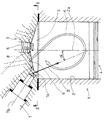
この図において,符号1は,シリンダ2を備えたシリンダブロックを,符号3は,前記シリンダブロック1の上面に前記シリンダ2の頂部を塞ぐように締結したシリンダヘッドを各々示す,前記シリンダブロック1におけるシリンダ2には,往復動するピストン4を内蔵し,前記シリンダヘッド3の下面には,前記シリンダ2内に開口する燃焼室5が凹み形成されている。
【0016】
また,前記シリンダヘッド3には,点火栓6が,前記シリンダ2における軸線2aの方向から見た平面視(図2)において前記燃焼室5の略中心の部位に位置するように着脱可能に装着されているとともに,燃料噴射弁7が,その先端部7aをシリンダ2における頂部のうちシリンダ2の内周面に近い部位においてシリンダ2内にのぞませ,且つ,当該燃料噴射弁7における軸線7bをシリンダ2における軸線2aの方向から見た平面視(図2)においてシリンダ2の略中心から半径方向の外向きに延びるようにして着脱可能に装着されている。
【0017】
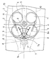
図において,符号8は,前記シリンダヘッド3に設けられ,一つの通路から二つに分岐するように構成したシリンダ2内への吸気ポートを示し,この両吸気ポート8は,前記シリンダ2における軸線2aの方向から見た平面視(図2)において,前記燃料噴射弁7における左右両側の部分に,当該吸気ポート8における軸線8aが半径方向の外向きに延びるようにして配設されている。
【0018】
なお,本実施の形態の場合,前記両吸気ポート8は,その軸線8aを前記シリンダ2における軸線2aの方向から見た平面視(図2)において,前記シリンダ2内に向かうにつ れて前記燃料噴射弁7における軸線7bに対して互いに離れていくように外向きに傾斜するという構成されている。
【0019】
また,この両吸気ポート8は,前記燃焼室5に対して斜め下向きに開口することにより,当該吸気ポート8からシリンダ内への吸気に図1及び図2に矢印Aで示すようにシリンダ2の軸線方向に旋回する吸気タンブル流を付与するように構成され,この両吸気ポート8の燃焼室5への開口部には,ポペット型の吸気弁9が設けられている。
【0020】
なお,前記シリンダヘッド3には,前記両吸気ポート8に対向して燃焼室5に開口する二つの排気ポート10が設けられ,この両排気ポート10の燃焼室5への開口部には,ポペット型の排気弁11が設けられている。
【0021】
一方,前記燃料噴射弁7における先端部7aには,燃料を,図1に矢印Bで示すように,シリンダ2における軸線2aに対して適宜角度αで前記ピストン4の頂面に向かって斜め下向きに噴出するようにした噴出孔12が穿設されている。
【0022】
この噴出孔12は,当該燃料噴射弁7における軸線7bと直角の方向に延びるスリットで,当該噴出孔12からの噴射燃料を比較的厚さの薄い平らな状態でシリンダ2における軸線2aの方向から見た平面視(図2)において適宜角度θ(約60度)の扇型に広がりながら噴出するように構成されている。
【0023】
そして,前記噴出孔12におけるスリットの幅寸法をTに,スリットの長さ寸法をWとした場合,その長さ寸法Wの幅寸法Tに対する割合(W/T)を大きくすることにより,前記スリットの噴出孔12から適宜広がり角度θの扇型に噴射される燃料における前記扇型の弦方向に沿った単位長さ当たりの噴射燃料量の全燃料噴射量に対する割合を,前記扇型の弦方向のうち両端部又はその近傍において大きく,扇型の弦方向のうち両端部又はその近傍以外の部分において小さくするようにする。
【0024】
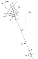
換言すると,図4に示すように,噴出孔12から適宜距離Sの箇所における扇型の弦寸法Lを,微小な単位長さδLの10箇所,すなわち,a,b,c,d,e,f,g,h,i,jに等分割し,これら各10箇所における噴射燃料量の全燃料噴射量に対する割合を,前記10箇所のうち扇型における弦方向の両端部又はその近傍におけるa箇所又はa,b箇所及びj箇所又はi,j箇所において大きく,前記10箇所のうち前記a箇所又はa,b箇所及びj箇所又はi,j箇所以外のc,d,e,f,g,h箇所において小さくするようにする。
【0025】
この場合において,本発明者達の実験によると,前記10箇所のうち弦方向の両端部又はその近傍におけるa箇所又はa,b箇所及びj箇所又はi,j箇所における噴射燃料量の全燃料噴射量に対する割合Cと,前記10箇所のうち弦方向の両端部又はその近傍におけるa箇所又はa,b箇所及びj箇所又はi,j箇所以外のc,d,e,f,g,h箇所における噴射燃料量の全燃料噴射量に対する割合Dとの差Xパーセント,つまり,C−D=Xパーセントは,前記噴出孔12のスリットにおける長さ寸法Wの幅寸法Tに対する割合(W/T)により,次の表1に示すようになるのであった。
【0026】
【表1】
以上の構成において,シリンダ2内には,ピストン4が下降動する吸気行程において燃料噴射弁7の両側に配設した吸気ポート8から吸気が導入されることにより,シリンダ2内は,図1及び図2に矢印Aで示すように,二つの吸気タンブル流が同時に形成され,この二つの吸気タンブル流の間に,前記燃料噴射弁7におけるスリットの噴射孔12から燃料が適宜広がり角度θの扇型に広がって噴射される。
【0028】
この場合において,前記燃料噴射弁7のスリットの噴射孔12から扇型に噴射される燃料における前記扇型の弦方向に沿った各10箇所における噴射燃料量の全燃料噴射量に対する割合を,前記扇型の弦方向に沿った10箇所のうち扇型における弦方向の両端部又はその近傍におけるa箇所又はa,b箇所及びj箇所又はi,j箇所において大きく,前記10箇所のうち前記a箇所又はa,b箇所及びj箇所又はi,j箇所以外のc,d,e,f,g,h箇所において小さくしたことにより,前記10箇所のうち扇型における弦方向の両端部又はその近傍におけるa箇所又はa,b箇所及びj箇所又はi,j箇所において噴射燃料量が多い噴射燃料は,その両側に形成される前記二つの吸気タンブル流を貫通することなく,前記両吸気タンブル流の流れに乗って当該吸気タンブル流に混合されることになる一方,前記10箇所のうち前記a箇所又はa,b箇所及びj箇所又はi,j箇所以外のc,d,e,f,g,h箇所における噴射燃料は,噴射燃料量が少なくて,前記両吸気タンブル流の間における吸気に混合されることになる。
【0029】
これにより,扇型に噴出される噴射燃料のうちシリンダ2の内周面に付着する燃料を大幅に低減できるとともに,燃焼室5の全体にわたって均質な混合気を形成することができる。
【0030】
この場合において,図示したように,前記両吸気ポート8を,その軸線8aが前記シリンダ2における軸線2aの方向から見た平面視(図2)において前記燃料噴射弁7における軸線7aに対してシリンダ2内に向かって外向きに傾斜するという構成にすることにより,両吸気ポート8からの吸気タンブル流は,シリンダ2の内周面に沿って旋回することになるから,噴射燃料のシリンダ内周面への付着を前記両吸気タンブル流にて阻止することの効果を更に向上できる利点がある。
【0031】
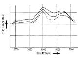
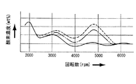
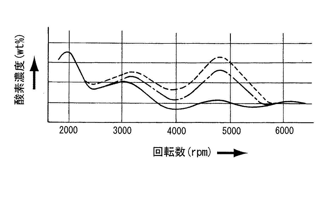
また,本発明者達は,シリンダ2の内径を68mmにした排気量660ccの三気筒内燃機関に,前記した本発明の構成を適用し,各回転数について,出力トルク,排気ガス中の炭化水素(HC)濃度及び酸素濃度を測定する実験を行った。その結果は,図5,図6及び図7に示す通りであった。
【0032】
この図において,
i).[点線で示す曲線」
前記したa〜jまでの10箇所のうち弦方向の両端部又はその近傍におけるa箇所又はa,b箇所及びj箇所又はi,j箇所における噴射燃料量の全燃料噴射量に対する割合Cと,前記10箇所のうち弦方向の両端部又はその近傍におけるa箇所又はa,b箇所及びj箇所又はi,j箇所以外のc,d,e,f,g,h箇所における噴射燃料量の全燃料噴射量に対する割合Dとの差を殆ど無くし,前記10箇所における噴射燃料量の全燃料噴射量に対する割合を,各箇所について略等しくした場合。
ii).[一点鎖線で示す曲線]
前記CとDとの差Xを,2.1パーセントにした場合。
iii).[実線で示す曲線]
前記CとDとの差Xを,5.1パーセントにした場合。
である。
【0033】
これらの実験結果から明らかなとおり,最も好ましいのは,前記噴出孔12のスリットにおける長さ寸法Wの幅寸法Tに対する割合を,前記CとDとの差Xが4パーセント以上とするように設定することにより,排気ガスのクリーン化及び出力の向上を,内燃機関における4000〜6000rpmの中速回転域において顕著に達成できるのであった。
【図面の簡単な説明】
【図1】 本発明の実施の形態を示す要部縦断正面図である。
【図2】 図1のII−II視底面図である。
【図3】 燃料噴射弁における先端部の拡大断面図である。
【図4】 図3のIV−IV視断面図である。
【図5】 回転数と出力トルクとの関係を示す図である。
【図6】 回転数と排気ガス中の炭化水素濃度との関係を示す図である。
【図7】 回転数と排気ガス中の酸素濃度との関係を示す図である。
【符号の説明】
1 シリンダブロック
2 シリンダ
3 シリンダヘッド
4 ピストン
5 燃焼室
6 点火栓
7 燃料噴射弁
7a 燃料噴射弁の先端部
7b 燃料噴射弁の軸線
8 吸気ポート
8a 吸気ポートの軸線
9 吸気弁
12 燃料噴射弁におけるスリット状の噴出孔[0001]
BACKGROUND OF THE INVENTION
The present invention relates to a structure of an internal combustion engine in which fuel is directly injected into a cylinder.
[0002]
[Prior art]
Conventionally, in this type of in-cylinder fuel injection type internal combustion engine, an ignition plug is disposed at a substantially central portion of the combustion chamber at the top of the cylinder as viewed from the axis of the cylinder, while a fuel injection valve for the cylinder is provided. The tip of the cylinder is disposed in the top of the cylinder close to the inner peripheral surface of the cylinder so as to be seen in the cylinder, and the fuel from the injection hole at the tip of the fuel injection valve is directed toward the top of the piston. The fuel injection valve is configured to inject obliquely downward, and the injection hole in the fuel injection valve is configured to be a circular hole having a circular cross section so that the fuel is injected in a conical shape.
[0003]
However, the injection of fuel into the cylinder in a conical shape is not only because the contact area with the air sucked into the cylinder is small and the vaporization of the fuel is low, but also among the fuel injected into the cone. , When it hits the top surface of the piston, the amount of fuel that changes its direction toward the inner peripheral surface of the cylinder increases, and accordingly, the amount of fuel that can be homogeneously mixed with the intake air decreases, and the fuel to the inner peripheral surface of the cylinder decreases. As a result of the adhesion, the lubricant on the inner peripheral surface of the cylinder disappears and seizure occurs on the piston.
[0004]
Therefore, Japanese Patent Application Laid-Open Nos. 3-78562 and 11-270440 as prior arts describe a slit-like jet extending in the direction perpendicular to the axis of the fuel injection valve through the injection hole at the tip of the fuel injection valve. By forming a hole, the fuel injected from the injection hole is configured to be ejected while spreading in a fan shape when viewed from the axial direction of the cylinder in a flat state with a relatively thin thickness. It proposes to eliminate the drawbacks of jetting.
[0005]
On the other hand, in a recent internal combustion engine, the intake port to the top of the cylinder is configured to apply an intake tumble flow that turns in the axial direction of the cylinder to the intake air from the intake port to the cylinder. It is well known to improve the combustibility of fuel.
[0006]
[Problems to be solved by the invention]
However, in the prior art, the injected fuel that is ejected from the slit-like ejection hole in the fuel injection valve while spreading in a fan shape as viewed from the cylinder axis in a relatively thin flat state, and the intake tumble flow As a result, the amount of fuel adhering to the inner surface of the cylinder at both ends of the fan-shaped fuel increases, and a homogeneous air-fuel mixture is formed in the combustion chamber at the top of the cylinder. Since it cannot be formed, there has been a problem that the exhaust gas is not cleaned, the output is improved, and the piston is not sufficiently prevented from being seized.
[0007]
It is a technical object of the present invention to further promote the purification of exhaust gas, the improvement of output, and the prevention of seizure of pistons by using the intake tumble flow according to the prior art.
[0008]
[Means for Solving the Problems]
In order to achieve this technical problem,
“At the top of the cylinder, a combustion chamber and an intake port into the cylinder are provided, and a fuel injection valve to the cylinder is inserted into the cylinder at a portion of the top of the cylinder close to the inner peripheral surface of the cylinder. The fuel injection valve is arranged so that the axis of the fuel injection valve extends radially outward from the approximate center of the cylinder when viewed from the axial direction of the cylinder, and fuel is ejected obliquely downward from the tip of the fuel injection valve. The injection hole is formed in a slit-like injection hole extending in a direction perpendicular to the axis of the fuel injection valve, and the fuel injected from the injection hole is relatively thin and flat from the axial direction of the cylinder. In-cylinder fuel injection type internal combustion engine configured to be blown out while spreading in a fan shape,
The intake port is composed of two intake ports, and both the intake ports are located on the left and right sides of the fuel injection valve when viewed from the axial direction of the cylinder, and the fuel line increases as the axis of the intake port goes into the cylinder. The fuel injection valve is disposed so as to be separated from each other with respect to the axis of the injection valve , and is configured to impart an intake tumble flow that swirls in the axial direction of the cylinder to the intake air from the intake port. The ratio of the amount of fuel injected per unit length along the fan-shaped chord direction to the total fuel injection amount in the fuel injected from the hole into the fan-shaped chord direction at or near both ends of the fan-shaped chord direction large, configured to reduce at both ends or portions other than the vicinity of the fan-shaped chordwise, further, the width dimension of the length dimension of the slit of the ejection hole The ratio of the injected fuel amount per unit length in the chord direction in the both ends of the fan-shaped string direction to the total fuel injection amount and the both ends of the fan-shaped string direction or the The difference between the ratio of the injected fuel amount per unit length in the chord direction in the portion other than the vicinity to the total fuel injected amount was set to 4% or more . "
It is characterized by that.
[0009]
[0010]
[Operation and effect of the invention]
In the cylinder, intake air is introduced from intake ports arranged on both sides of the fuel injection valve in the intake stroke, so that two intake tumble flows are formed in the cylinder at the same time. In addition, fuel is injected from the injection hole in the fuel injection valve while spreading in a fan shape.
[0011]
In this case, the ratio of the amount of fuel injected per unit length along the chord direction of the sector of the fuel injected into the sector from the injection hole of the fuel injection valve to the total amount of fuel injection of the sector The unit length is large at both ends or in the vicinity of the chord direction and small at both ends or in the vicinity of the fan-shaped chord direction. The injected fuel with a large amount of fuel injected per shot is mixed with the intake tumble flow on the flow of both intake tumble flows without penetrating the two intake tumble flows formed on both sides thereof. On the other hand, the amount of fuel injected per unit length along the fan-shaped chord direction is small in the injected fuel in the fan-shaped chord direction other than both ends or the vicinity thereof. It will be mixed into the intake between Le stream.
[0012]
As a result, the fuel adhering to the inner peripheral surface of the cylinder among the fuel injected into the fan shape can be greatly reduced, and a homogeneous air-fuel mixture can be formed throughout the combustion chamber. Therefore, the exhaust gas cleaning, the output improvement, and the piston seizure prevention can be improved more reliably than the prior art.
[0013]
In particular, according to the experiments described below by the present inventors, in addition to the above-described configuration, the ratio of the length dimension in the slit of the ejection hole to the width dimension is determined by measuring the ratio of both ends of the fan-shaped string direction or the vicinity thereof. The ratio of the injected fuel amount per unit length in the chord direction to the total fuel injection amount and the injected fuel amount per unit length in the chord direction in the fan-shaped chord direction other than both ends or the vicinity thereof All by the structure that the difference between the ratio is set to be more than 4 percent with respect to the fuel injection amount, wherein the effect, that is, the improvement of cleaner and output of the exhaust gas, rotating medium speed in an internal combustion engine It was possible to greatly improve in the area.
[0014]
DETAILED DESCRIPTION OF THE INVENTION
Hereinafter, embodiments of the present invention will be described with reference to FIGS.
[0015]
In this figure,
[0016]
Further, the
[0017]
In the figure,
[0018]
In the case of this embodiment, the two
[0019]
The
[0020]
The
[0021]
On the other hand, as shown by an arrow B in FIG. 1, the fuel is injected obliquely downward toward the top surface of the
[0022]
The
[0023]
When the width dimension of the slit in the
[0024]
In other words, as shown in FIG. 4, the fan-shaped chord dimension L at the location of the appropriate distance S from the
[0025]
In this case, according to the experiments by the present inventors, the total fuel injection of the injected fuel amount at the a position or the a, b position and j position or the i, j position at or near both ends in the chord direction among the ten positions. The ratio C with respect to the quantity, and at the a, a, b, and j, or c, d, e, f, g, and h places other than the a and a, b, and j or i, j at both ends in the chord direction among the ten places. The difference X percent of the injected fuel amount with respect to the ratio D to the total fuel injected amount, that is, C−D = X percent, depends on the ratio (W / T) of the length dimension W to the width dimension T in the slit of the
[0026]
[Table 1]
In the above-described configuration, intake air is introduced into the
[0028]
In this case, the ratio of the amount of injected fuel to the total fuel injection amount at each of ten locations along the direction of the fan-shaped string in the fuel injected in a fan shape from the
[0029]
Thereby, the fuel adhering to the inner peripheral surface of the
[0030]
In this case, as shown in the figure, the two
[0031]
In addition, the present inventors applied the above-described configuration of the present invention to a three-cylinder internal combustion engine having a displacement of 660 cc in which the inner diameter of the
[0032]
In this figure,
i). [Curve indicated by dotted line]
Of the ten locations from a to j described above, the ratio C to the total fuel injection amount of the injected fuel amount at the positions a, a, b and j or i, j at or near both ends in the chord direction , Total fuel injection of the amount of fuel injected at c, d, e, f, g, and h other than a, a, b, and j, or i, j at both ends of the chord direction or in the vicinity thereof When the difference from the ratio D to the amount is almost eliminated, and the ratio of the injected fuel amount at the ten locations to the total fuel injection amount is made substantially equal at each location.
ii). [Curve indicated by a dashed line]
When the difference X between C and D is 2.1%.
iii). [Curve indicated by solid line]
When the difference X between C and D is 5.1 percent.
It is.
[0033]
As is clear from these experimental results, the most preferable is that the ratio of the length dimension W to the width dimension T in the slit of the
[Brief description of the drawings]
FIG. 1 is a longitudinal sectional front view showing a main part of an embodiment of the present invention.
FIG. 2 is a bottom view taken along the line II-II in FIG.
FIG. 3 is an enlarged cross-sectional view of a tip portion of a fuel injection valve.
4 is a cross-sectional view taken along the line IV-IV in FIG. 3;
FIG. 5 is a diagram showing a relationship between a rotation speed and an output torque.
FIG. 6 is a graph showing the relationship between the rotational speed and the hydrocarbon concentration in the exhaust gas.
FIG. 7 is a graph showing the relationship between the rotational speed and the oxygen concentration in the exhaust gas.
[Explanation of symbols]
DESCRIPTION OF
Claims (1)
前記吸気ポートを二つの吸気ポートに構成して,この両吸気ポートを,シリンダの軸線方向から見て前記燃料噴射弁の左右両側の部位に当該吸気ポートにおける軸線が前記シリンダ内に向かうにつれて前記燃料噴射弁における軸線に対して互いに離れるようにして配設するとともに,当該吸気ポートからの吸気にシリンダの軸線方向に旋回する吸気タンブル流を付与するように構成する一方,前記燃料噴射弁の噴出孔から扇型に噴射される燃料における前記扇型の弦方向に沿った単位長さ当たりの噴射燃料量の全燃料噴射量に対する割合を,前記扇型の弦方向のうち両端部又はその近傍において大きく,扇型の弦方向のうち両端部又はその近傍以外の部分において小さくなるように構成し,更に,前記噴出孔のスリットにおける長さ寸法の幅寸法に対する割合を,前記扇型の弦方向のうち両端部又はその近傍における前記弦方向の単位長さ当たりの噴射燃料量の全燃料噴射量に対する割合と前記扇型の弦方向のうち両端部又はその近傍以外の部分における前記弦方向の単位長さ当たりの噴射燃料量の全燃料噴射量に対する割合との差が4パーセント以上になるように設定したことを特徴とする筒内燃料噴射型内燃機関の構造。A combustion chamber and an intake port into the cylinder are provided at the top of the cylinder, while a fuel injection valve to the cylinder is inserted into the cylinder at a portion of the top of the cylinder close to the inner peripheral surface of the cylinder. The fuel injection valve is arranged such that the axis of the fuel injection valve extends radially outward from the approximate center of the cylinder when viewed from the axial direction of the cylinder, and fuel is ejected obliquely downward from the tip of the fuel injection valve. The injection hole is formed in a slit-like injection hole extending in a direction perpendicular to the axis of the fuel injection valve, and the fuel injected from the injection hole is viewed from the axial direction of the cylinder in a relatively thin and flat state. In-cylinder fuel injection type internal combustion engine configured to spray while spreading in a fan shape,
The intake port is composed of two intake ports, and both the intake ports are located on the left and right sides of the fuel injection valve when viewed from the axial direction of the cylinder, and the fuel line increases as the axis of the intake port goes into the cylinder. The fuel injection valve is disposed so as to be separated from each other with respect to the axis of the injection valve , and is configured to impart an intake tumble flow that swirls in the axial direction of the cylinder to the intake air from the intake port. The ratio of the amount of fuel injected per unit length along the fan-shaped chord direction to the total fuel injection amount in the fuel injected from the hole into the fan-shaped chord direction at or near both ends of the fan-shaped chord direction large, configured to be smaller at both end portions or portions other than the vicinity of the fan-shaped chordwise, further, the width of the length dimension of the slit of the ejection hole The ratio of the injected fuel quantity per unit length in the chord direction at or near both ends of the fan-shaped chord direction to the total fuel injection amount and both ends of the fan-shaped chord direction In- cylinder fuel injection type internal combustion engine characterized in that the difference between the ratio of the injected fuel quantity per unit length in the chord direction in the part other than the vicinity thereof to the ratio of the total fuel injection quantity is set to 4% or more Structure.
Priority Applications (1)
| Application Number | Priority Date | Filing Date | Title |
|---|---|---|---|
| JP2002023987A JP3999975B2 (en) | 2002-01-31 | 2002-01-31 | Structure of in-cylinder fuel injection internal combustion engine |
Applications Claiming Priority (1)
| Application Number | Priority Date | Filing Date | Title |
|---|---|---|---|
| JP2002023987A JP3999975B2 (en) | 2002-01-31 | 2002-01-31 | Structure of in-cylinder fuel injection internal combustion engine |
Publications (2)
| Publication Number | Publication Date |
|---|---|
| JP2003227444A JP2003227444A (en) | 2003-08-15 |
| JP3999975B2 true JP3999975B2 (en) | 2007-10-31 |
Family
ID=27746548
Family Applications (1)
| Application Number | Title | Priority Date | Filing Date |
|---|---|---|---|
| JP2002023987A Expired - Fee Related JP3999975B2 (en) | 2002-01-31 | 2002-01-31 | Structure of in-cylinder fuel injection internal combustion engine |
Country Status (1)
| Country | Link |
|---|---|
| JP (1) | JP3999975B2 (en) |
Families Citing this family (1)
| Publication number | Priority date | Publication date | Assignee | Title |
|---|---|---|---|---|
| JP4619989B2 (en) | 2005-07-04 | 2011-01-26 | 株式会社デンソー | Fuel injection valve |
-
2002
- 2002-01-31 JP JP2002023987A patent/JP3999975B2/en not_active Expired - Fee Related
Also Published As
| Publication number | Publication date |
|---|---|
| JP2003227444A (en) | 2003-08-15 |
Similar Documents
| Publication | Publication Date | Title |
|---|---|---|
| JP4280928B2 (en) | Direct injection spark ignition internal combustion engine | |
| US7195000B2 (en) | Fuel injector designed to optimize pattern of fuel spray | |
| EP1069291B1 (en) | In-cylinder direct-injection spark-ignition engine | |
| CN1637268A (en) | Intake port structure for internal combustion engine | |
| JP3999975B2 (en) | Structure of in-cylinder fuel injection internal combustion engine | |
| US3374773A (en) | Diesel engine | |
| JPH03189320A (en) | Internal combustion engine | |
| JP5006905B2 (en) | In-cylinder injection spark ignition internal combustion engine | |
| JP3904858B2 (en) | In-cylinder fuel injection internal combustion engine | |
| EP1517017B1 (en) | Spark-ignition direct-injection engine | |
| JP3948225B2 (en) | In-cylinder direct injection internal combustion engine | |
| JP3867319B2 (en) | In-cylinder direct injection internal combustion engine | |
| JP2005042586A (en) | Cylinder fuel injection type internal combustion engine | |
| EP0982481A2 (en) | In-cylinder injection type of engine | |
| JPS6394021A (en) | Direct injection type diesel engine | |
| JP2666135B2 (en) | Intake system for fuel injection engine | |
| JP2020122414A (en) | Direct injection internal combustion engine | |
| JP3882611B2 (en) | Fuel injection device and fuel injection valve for internal combustion engine | |
| JP6798460B2 (en) | Internal combustion engine | |
| JP4134736B2 (en) | In-cylinder direct injection spark ignition internal combustion engine | |
| JP4120799B2 (en) | Fuel injection device for internal combustion engine | |
| JP2004225629A (en) | Cylinder injection type spark ignition internal combustion engine | |
| JP2002250232A (en) | Internal combustion engine of cylinder injection of fuel type | |
| JP4103332B2 (en) | V-type carburetor | |
| CS251156B1 (en) | Combustion chamber of compression ignition engines with direct fuel injection |
Legal Events
| Date | Code | Title | Description |
|---|---|---|---|
| A621 | Written request for application examination |
Free format text: JAPANESE INTERMEDIATE CODE: A621 Effective date: 20041201 |
|
| A977 | Report on retrieval |
Free format text: JAPANESE INTERMEDIATE CODE: A971007 Effective date: 20070119 |
|
| A131 | Notification of reasons for refusal |
Free format text: JAPANESE INTERMEDIATE CODE: A131 Effective date: 20070418 |
|
| A521 | Written amendment |
Free format text: JAPANESE INTERMEDIATE CODE: A523 Effective date: 20070614 |
|
| TRDD | Decision of grant or rejection written | ||
| A01 | Written decision to grant a patent or to grant a registration (utility model) |
Free format text: JAPANESE INTERMEDIATE CODE: A01 Effective date: 20070718 |
|
| A61 | First payment of annual fees (during grant procedure) |
Free format text: JAPANESE INTERMEDIATE CODE: A61 Effective date: 20070810 |
|
| R150 | Certificate of patent or registration of utility model |
Free format text: JAPANESE INTERMEDIATE CODE: R150 |
|
| FPAY | Renewal fee payment (event date is renewal date of database) |
Free format text: PAYMENT UNTIL: 20100817 Year of fee payment: 3 |
|
| FPAY | Renewal fee payment (event date is renewal date of database) |
Free format text: PAYMENT UNTIL: 20120817 Year of fee payment: 5 |
|
| FPAY | Renewal fee payment (event date is renewal date of database) |
Free format text: PAYMENT UNTIL: 20140817 Year of fee payment: 7 |
|
| LAPS | Cancellation because of no payment of annual fees |