JP3998424B2 - Optical disc recording / reproducing apparatus - Google Patents
Optical disc recording / reproducing apparatus Download PDFInfo
- Publication number
- JP3998424B2 JP3998424B2 JP2001048493A JP2001048493A JP3998424B2 JP 3998424 B2 JP3998424 B2 JP 3998424B2 JP 2001048493 A JP2001048493 A JP 2001048493A JP 2001048493 A JP2001048493 A JP 2001048493A JP 3998424 B2 JP3998424 B2 JP 3998424B2
- Authority
- JP
- Japan
- Prior art keywords
- defect
- disk
- optical disc
- recording
- pickup
- Prior art date
- Legal status (The legal status is an assumption and is not a legal conclusion. Google has not performed a legal analysis and makes no representation as to the accuracy of the status listed.)
- Expired - Fee Related
Links
Images


Description
【0001】
【発明の属する技術分野】
本発明は光ディスクに対して情報の記録及び再生を行う光ディスク記録再生装置に関し、特に光ディスク上の汚れ又はキズ等のディフェクト部を検出する光ディスク記録再生装置に関する。
【0002】
【従来の技術】
光ディスク記録再生装置において、ディスク上に汚れあるいはキズ等のディフェクトがあると、トラッキングサーボ更にはフォーカスサーボが不可能となり、ディフェクト部に対する情報の記録又は再生が不可能となることがある。
【0003】
従来、光ディスク全面にわたりディフェクトを検出する方法としては、次に示すような技術がある。第1に、M個所のトラックシークを行い、それぞれN周のトラッキングオン再生を行い、ディスク全面のディフェクトを検出する方法である。
【0004】
第2の方法としては、特開平6−203466号公報のように、トラックカウントキックすなわち光ピックアップをNトラック分高速移動し、そのとき横切ったトラックの数と、トラッキングオンアドレスの差異つまりトラックカウントキックを行う前後のトラッキングオン再生で読取ったアドレスの差異から求められるトラック数との差によりディフェクト検出する方法が有る。
【0005】
【発明が解決しようとする課題】
上記M個所のトラックシークを行う第1の方法では、ディスクのゾーン単位のシークと一周以上のトラッキングオン再生動作を繰り返さなければならず、ディスク全面のディフェクトを検出するのに時間がかかる。その為、ディスク挿入毎などに必ずディフェクト検査をするような製品仕様にはし難い。
【0006】
上記第2の方法では、トラックカウントキック動作の前後でトラッキングオン再生して、物理アドレスのデコードを必ず行う必要があるので、手順に煩雑な点がある。又、ディフェクト上にトラッキングオンした場合の動作異常を考慮していない。
【0007】
従って本発明は、短時間で光ディスク全面にわたりディフェクトを検出し、情報記録不具合を未然に防ぐことができる光ディスク記録再生装置を提供することを目的とする。
【0008】
【課題を解決するための手段】
上記目的を達成するために本発明の光ディスク記録再生装置は、主制御手段が、トラッキング制御手段によるトラッキング制御を行わずに、フォーカス制御手段、フィード制御手段、回転速度制御手段による制御を実行させている際に、ディフェクト判断手段は光ディスクを反射したレーザービームを受光する受光素子から得られるトラッキングエラー信号のピーク値を、基準閾値と比較することにより、前記レーザービームが前記光ディスク上のディフェクト部を照射しているか判断する。
【0009】
一般に光ディスクの反射光レベルは、正常なディスク盤面を反射したときより、ディフェクト部を反射したときの方が低い。従って、前記ディフェクト判断手段は、トラッキングエラー信号のピーク値が所定の基準閾値より低いとき、ディフェクトありと判断する。
【0010】
一般にトラッキングエラー信号はレーザービームが光ディスクの情報記録部を照射しているときより、未記録部を照射しているときの方が振幅レベルが低い。従って、レーザービームが情報記録部を照射している場合と、未記録部を照射している場合とでは互いに異なる基準閾値が適用される。
【0011】
又、前記反射光レベルとして、光ディスクを反射したLED光を受光する受光素子から得られる反射光量を用いることができる。更に前記反射光レベルとして、レーザービームのフォーカスがディスクの表面に制御されている状態で得られるフォーカスエラー信号の振幅値を用いることができる。従って、ディフェクト検出過程時に、ディスク盤面の異常によるピックアップサーボの暴走を伴ない難い。
【0012】
又、本発明の光ディスク記録再生装置では、光ディスクの回転周期と、ピックアップの移動量と、前記ディフェクト判断手段によるディフェクト判断結果を元に、光ディスク上のディフェクト部の面積が求められる。 この結果、ディスク盤面全体の汚れや傷を、直ちに(1〜2秒程度で)検出するディフェクト検出機能が提供される。ディスク上にディフェクトが検出された場合、その旨がディフェクト部の面積と共にユーザに警告される。
【0013】
【発明の実施の形態】
以下、図面を参照しながら本発明の実施の形態について詳細に説明する。
【0014】
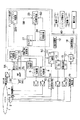
図1は本発明の第1の実施形態に係る記録再生装置の構成を示すブロック図である。情報記録再生用の光ディスク1は、スピンドルモータ2によって所定速度で回転する。回転速度検出部19はスピンドルモータ2に設けられたエンコーダから出力される信号からFGパルスを検出し提供する。このFGパルスはスピンドルモータ2の回転角を示す信号であって、その周波数はスピンドルモータ2の回転速度に対応する。ディスク回転周波数制御(AFC)部17は回転速度検出部19から提供されるFGパルスの周波数と、システム制御MPU40により設定され速度目標値記憶部18に記憶された回転速度目標値とを比較し、スピンドルモータ2の回転速度が回転速度目標値に一致するよう制御信号を提供する。この制御信号は回転速度イコライザ15及びアンプ16により、スピンドルモータ2の駆動信号に変換される。
【0015】
光ピックアップ4はレーザービームを光ディスク1に照射することにより、光ディスク1に対して情報の記録及び再生を行う。光ピックアップ4は光ディスク1を反射したレーザービームを4分割フォトダイオード(後述される)により受光し、フォトダイオードの光検出信号PDSIGを提供する。RFアンプ5は光ピックアップから提供される光検出信号PDSIGを増幅し、RFレベル信号、トラックエラー信号TE、フォーカスエラー信号FEを提供する。アドレスデコード部29はRFアンプ5から提供されるRFデータをデコードしアドレスを提供する。
【0016】
フォーカス制御部6はフォーカスサーボを含む処理を実行する。つまりフォーカス制御部6は、ピックアップ4から光ディスク1に照射されるレーザービームのフォーカスが前記ディスクの記録面となるよう前記光ピックアップを制御する。FO.OK判定部31は該フォーカスが前記ディスクの記録面となっているか判定する。
【0017】
トラッキング制御部8はトラッキングサーボを含む処理を実行する。つまりトラッキング制御部8は、レーザービームが前記ディスク上のトラックに追随するよう前記光ピックアップを制御する。TRK.OK判定部32はレーザービームが前記ディスク上のトラックに追随しているか判定する。
【0018】
送りモータ3は光ピックアップ4を光ディスク1の半径方向に移動する。フィード速度検出部10は送りモータ3に設けられたエンコーダの出力信号からTAC信号を検出し提供する。このTAC信号は送りモータ2の回転角を示す信号であって、その周波数は光ピックアップ4の移動速度すなわちフィード速度に対応する。フィードキック制御部11は、フィード速度検出部10から提供されるTAC信号の周波数と、システム制御MPU40により設定され速度目標値記憶部12に記憶されたフィード速度目標値とを比較し、TAC信号の周波数がフィード速度目標値12に一致するよう制御信号を提供する。この制御信号はフィードイコライザ13及びアンプ14により送りモータ3の駆動信号に変換される。
【0019】
ディフェクト検出部20はRFアンプ5から提供されるRFレベル信号及びトラッキングエラーTE信号から、光ディスク1上の汚れやキズ等のディフェクトを検出する。更にディフェクト検出部20は、フィード速度検出部10から提供される光ピックアップ4のフィード速度信号及び回転速度検出部19から提供されるスピンドルモータ2の回転速度信号から、上記検出されたディフェクトの面積を計算する。
【0020】
システム制御MPU40(主制御手段)はこの光ディスク記録再生装置を制御バスを介して総合的に制御する。
【0021】
次に本実施形態の動作を説明する。図2は本実施形態の動作を示すフローチャートである。システム制御MPU40は、ディスク1を適当なFG周期で回転制御して、フォーカス制御部6によりフォーカスサーボをオンする(S1)。これは従来の光ディスク再生装置の手順と同様である。
【0022】
その後、システム制御MPU40は光ディスクの速度目標値記憶部18の値をディフェクト検出動作時の目標速度に設定し(S2)、ディスク回転周波数制御(AFC)がロックした事を確認後、光学式ピックアップ4を光ディスク半径方向に一定速度で移動させるフィードキック動作を行う(S3)。手順としては、先ずフィードキックの速度目標値記憶部12の値を所定の値Vsに設定し、ディスク最内周へのフィードキックを命令し、フィードが最内周に到達したらフィードキックを停止し、次に外周側にフィードキックを行う。
【0023】
システム制御MPU40は最内周からの光学式ピックアップ4の移動量を、フィード速度検出部10から提供されるTACパルスをカウントするTACカウント部27を用いて判断する。ピックアップ4がディフェクト検出を行うべきエリアの開始位置に到達したら(S4)、システム制御MPUはディフェクト検出部20に対してディフェクト検出を命令する(S5)。このディフェクト検出を行うべきエリアとは光ディスク内周側のリードインエリアと外周側のリードアウトエリアの間の記録エリアを示す。
【0024】
TEディフェクト判定部22aはトラッキングエラーTE信号をピーク検波してディフェクトを判定する。
【0025】
判定の様子を図3に示す。図3の(a)〜(d)に示す信号は図1の信号1A〜1Dに対応する。TEディフェクト判定部22aはトラッキングエラーTE信号1Cをピーク検波し、ピーク検波結果が基準となる閾値以下であればディフェクト有りと判定する。
【0026】
ここでディスクの反射率がデータ記録済みの領域か否かで異なることにより、トラッキングエラーピーク値の正常値が異なる場合を想定し、図3(c)の閾値thL及びthHのように、データー有無により前記ピーク検波閾値を切り替えている。この例ではデータ記録済み領域で反射率が低下し、トラッキングエラーのピーク値が下がる場合についてその閾値切り替え手順を記述している。図3(a)及び(b)において、ハイレベルは記録済み領域を示し、ローレベルは未記録領域を示す。図1のディフェクト検出部20に入力されたRFレベル信号1Aのレベルをレベル検出部21で判定し、記録済みか否かを判定している。
【0027】
図1のディフェクト面積計算部23はディフェクト判定結果1Dと、ディスク周期計測結果1Eと、TAC信号1Fから求めたフィード量(ピックアップ4の移動量)を元にディフェクト面積を算出する(S6)。図4(a)〜(c)に3つの検出結果信号1D〜1Fの関係とディフェクト面積の算出式を示す。
【0028】
システム制御MPU40はピックアップ4がディフェクト検出を行うべきエリアの終端まで至った時に(S7)、ディフェクト検出を終了する命令をシステムに出力し、フィードキックを停止し(S8)、ディフェクト検出結果をディフェクト検出部20aより読み出す(S9)。ディスク上にディフェクトが存在した場合は、警告手段41により製品ユーザーに警告を与える(S10、S11)。
【0029】
この製品ユーザーに対する警告を行う場合に、図4のような手法で算出したディフェクト面積概算値を、警告と同時にユーザーに表示するようにしても良い。また、製品ユーザーに対して、ディスククリーニングを促すような警告をしても良い。
【0030】
また上記では、ディフェクト検出を行うべきエリアの判定をフィード速度検出部10からのTAC信号を用いて行ったが、トラッキングエラーTE信号1Cを2値化カウントすることによって行っても構わない。
【0031】
次に本発明の第2の実施形態を説明する。図5は第2の実施形態に係る記録再生装置の構成を示すブロック図である。先ず、システム制御MPU40はディスク1を適当なFG周期で回転制御して、ピックアップ4内に設けられたディフェクト検出用LEDをオンする。
【0032】
その後、第1の実施例と同様に、システム制御MPU40はディスク速度目標値をディフェクト検出動作時の目標速度に設定し、ディスク回転周波数制御(AFC)がロックした事を確認後に、フィードキックの速度目標値を設定し、ディスク最内周へのフィードキックを命令し、フィードが最内に周到達したらフィードキックを停止し、次に外周側にフィードキックを行う。
【0033】
システム制御MPU40はTACカウント部25の最内周からのカウント値を参照してピックアップ4がディフェクト検出を行うべきエリアに到達したことを確認後、ディフェクト検出部20bに対してディフェクト検出を命令する。ディフェクト判定部22bはLED光の反射レベル信号5Aから、特定レベルを閾値としてディフェクトを判定する。
【0034】
判定の仕組みを図6に示す。図6(a)のように、LED42からディスク盤面に照射されたLED光は、ディスク1及びミラー44を反射しフォトディテクタ43で受光される。図6(b)のように、フォトディテクタ43は例えば4分割構造であり、受光した光を加算することにより前記反射光レベルを検出する。
【0035】
図7はディフェクト検出の様子を示す。図7(a)のように反射光レベル5Aが所定のディフェクト検出閾値thD以下であれば、図7(b)のようにディスク盤面にディフェクトが有ると判断する。
【0036】
図5のディフェクト面積計算部23は、ディフェクト判定結果5Bとディスク周期計測結果5Dとから求められるフィード量検出結果5Cを元にディフェクト面積を算出する。図8に3つの検出結果の関係と面積算出式を示す。
【0037】
システム制御MPU40は光ピックアップ4がディフェクト検出を行うべきエリアの終了位置まで至った時に、前述したようにディフェクト検出を終了する命令をシステムに出力し、フィードキックを停止しディフェクト状態をディフェクト検出部20より読み出す。そして、ディスク上にディフェクトが存在した場合は、警告手段41により製品ユーザーに警告を与える。
【0038】
尚、図6に示したディフェクト検出用のLED42と、フォトディテクタ43は、情報の記録再生用光学系とは別途に設けられた光学系であり、情報の記録再生用光学系の光源より波長の長い光源によって構成されることが望ましい。たとえば、光ディスク1の傾きを検出するために設けられたチルトセンサの光学系を兼用する構成とすることが可能である。このように光学系を兼用することで、別途にディフェクト検知光学系を設けることなくコンパクトな構成とすることができる。
【0039】
また、複数の規格のディスクに対応するように、複数の光学系を備えている場合、最も波長の長い光源による光学系を用いる構成とすることが望ましい。
【0040】
次に本発明の第3の実施形態を説明する。図9は第3の実施形態に係る記録再生装置の構成を示すブロック図である。先ず、システム制御MPU40はディスク1を適当なFG周期でドライブして、ディスク1の表面を目標点としてフォーカスサーボをオンする。フォーカスサーボ目標点を図10に示す。フォーカスエラー信号上には記録面に対するフォーカスゼロクロス点F1とディスク表面に対するフォーカスゼロクロス点F2が存在している。本実施形態の場合、このゼロクロス点F2にフォーカスが調節される。
【0041】
次にシステム制御MPU40は第1の実施例と同様に、ディスク速度目標値(18)をディフェクト検出動作時の目標速度に設定し、ディスクAFCがロックした事を確認後に、フィードキック速度目標値(12)を設定し、ディスク最内周へのフィードキックを命令し、フィードが最内周に到達したらフィードキックを停止し、次に外周側にフィードキックを行う。
【0042】
システム制御MPUはピックアップ4がディフェクト検出を行うべきエリアに到達したら、デフェクト検出部20に対してディフェクト検出動作を命令する。ディフェクト判定部20cは反射レベル信号9Aから、特定レベルを閾値としてディフェクトを判定する。
【0043】
判定の仕組みを図11に示す。図11(a)のように、レーザーダイオード45からディスク盤面に照射されたレーザー光は、ディスク1及びハーフプリズム47を反射しフォトディテクタ45で受光される。図11に示した光学系は、情報の記録再生用光学系である。フォトディテクタ46は図11(a)のように、例えば4分割構造であり、受光した光の検出信号を加算することにより前記反射光レベルを検出する。
【0044】
図12はディフェクト検出の様子を示す。図12(a)のように反射光レベル9Aが所定のディフェクト検出閾値thE以下であれば、図12(b)のようにディスク盤面にディフェクトが有ると判断する。
【0045】
図9のディフェクト面積計算部23はディフェクト判定結果9Bとディスク周期計測結果9DとTAC信号9Cから求められるフィード量検出結果を元にディフェクト面積を算出する。図13に3つの検出結果の関係と面積算出式を示す。
【0046】
システム制御MPU40は光ピックアップ4がディフェクト検出を行うべきエリアの終了位置まで至った時に、前述したようにディフェクト検出を終了する命令をシステムに出力し、フィードキックを停止しディフェクト状態をディフェクト検出部20より読み出す。そして、ディスク上にディフェクトが存在した場合は、警告手段41により製品ユーザーに警告を与える。
【0047】
次に本発明の第4の実施形態を説明する。第4の実施形態では、第1の実施形態に係る動作を実行時に、図3(c)のトラッキングエラーTE信号を2値化したトラックカウント信号を用いて概略のディフェクト位置アドレスを検出する。
【0048】
図14は第4の実施形態に係る記録再生装置の構成を示すブロック図である。先ずシステム制御MPU40は前述したように、光ディスク1を適当なFG周期で回転制御して、ディスク1の情報記録面にフォーカスサーボをオンする。
【0049】
その後、システム制御MPU40はディスク速度目標値(18)をディフェクト検出動作時の目標速度に設定し、ディスクAFCがロックした事を確認後に、フィードキック速度目標値(12)を設定し、ディスク最内周へのフィードキックを命令し、フィードが最内に周到達したらフィードキックを停止し、次に外周側にフィードキックを行う。
【0050】
システム制御MPU40は最内周からのTAC信号のパルス数をカウントし、ディフェクト検出を行うべきエリアに到達したら、ディフェクト検出部20に対してディフェクト検出動作を命令する。この時、トラックカウント部25はカウント値をクリアし、トラックカウント開始状態となる。
【0051】
TEディフェクト判定部22aによってディフェクトが検出された時に、ディフェクト概略アドレス判定部26は、トラックカウント部25のトラックカウント値を読み出す。このトラックカウント値はそのままディフェクトの存在するトラックの位置を示しており、ディフェクト開始位置の概略アドレスとなる。
【0052】
同様に、ディフェクト終了位置を通過直後のトラックカウント値により、ディフェクト終了位置の概略アドレスを検出できる。各概略アドレスはディフェクト概略アドレス判定部26の中に記憶する。
【0053】
システム制御MPUはフィードキックパルス数がディフェクト検出を行うべきエリアの終了位置まで至った時に、前述したようにディフェクト検出を終了する命令をシステムに出力し、フィードキックを停止し、ディフェクト概略アドレスをディフェクト概略アドレス検出部26より読み出す。そしてその結果を元にシステムコントロールまたは製品ユーザーに対する警告などをする。
【0054】
次に本発明の第5の実施形態を説明する。ディフェクトによりトラックカウントが欠落する場合が考えられる。従って、本実施形態では、光学式ピックアップの移送手段に設けられたエンコーダ信号であるTACパルスカウントとトラックカウントを併用してディフェクトアドレスを求める。
【0055】
この第5の実施形態に係る記録再生装置の構成は図14の第4の実施形態と同様である。先ずシステム制御MPU40は、前述したようにディスクを適当なFG周期でドライブして、フォーカスサーボをオンする。
【0056】
その後、システム制御MPU40はディスク速度目標値(18)をディフェクト検出動作時の目標速度に設定し、ディスクAFCがロックした事を確認後に、フィードキック速度目標値(12)を設定し、ディスク最内周へのフィードキック命令をし、フィードが最内周に到達したらフィードキックを停止し、次に外周側にフィードキックを行う。
【0057】
システム制御MPU40はピックアップ4がディフェクト検出を行うべきエリアに到達したら、デフェクト検出部20に対してディフェクト検出動作を命令する。この時、トラックカウント部25はカウント値がクリアされ、トラックカウントを開始する。同時にTACカウント部27も、カウント値がクリアされ、TACパルスのカウントを開始する。その後、TACパルス発生毎にTACカウント部27は、トラックカウント部25のカウント値をクリアし、トラックカウント再開を指令する。
【0058】
ディフェクト判定部22aによってディフェクトが検出された時に、ディフェクト概略アドレス判定部26aは、TACカウント部27のTACカウント値と、トラックカウント部25のトラックカウント値を読み出す。このTACカウント数とトラックカウント数のカウント値が、ディフェクト検出位置の概略アドレスとなる。
【0059】
同様に、ディフェクト終了部通過直後のTACカウント値とトラックカウント値により、ディフェクト終了位置の概略アドレスを検出できる。各概略アドレスはディフェクト概略アドレス判定部26aの中に記憶する。
【0060】
システム制御MPU40はフィードキックパルス数がディフェクト検出を行うべきエリアの終了位置まで至った時に、前述したようにディフェクト検出を終了する命令をシステムに出力し、フィードキックを停止し、ディフェクト概略アドレスをディフェクト概略アドレス判定部26aより読み出す。そしてその結果を元にシステムコントロールまたは製品ユーザーに対する警告などをする。
【0061】
上記トラックカウント値については、ディフェクトの影響による、カウント欠落が有りうるが、TACパルス長以下のカウント誤差発生の可能性があるものの、ディフェクト位置の概略アドレスを推測可能である。
【0062】
次に本発明の第6の実施形態を説明する。上記実施形態について、前記トラックカウント部25は、タイマーに置き換えても良い。
【0063】
図15は第6の実施形態に係る記録再生装置の構成を示すブロック図である。先ずシステム制御MPU40は、前述したようにディスクを適当なFG周期でドライブして、フォーカスサーボをオンする。
【0064】
その後、システム制御MPU40はディスク速度目標値をディフェクト検出動作時の目標速度に設定し、ディスクAFCがロックした事を確認後に、フィードキック速度目標値を設定し、ディスク最内周へのフィードキックを命令し、フィードが最内周に到達したらフィードキックを停止し、次には外周側にフィードキックを行う。
【0065】
システム制御MPU40は、ピックアップ4がディフェクト検出を行うべきエリアに到達したら、デフェクト検出部20に対してディフェクト検出動作を命令する。この時、タイマー部28はカウント値がクリアされ、タイマー動作を開始する。同時にTACカウント部27も、カウント値がクリアされ、TACカウントを開始する。その後、TACパルス発生毎にTACカウント部27は、タイマー部28のカウント値をクリアし、タイマー動作再開を指令する。
【0066】
ディフェクト判定部22aによってディフェクト検出がされた時に、ディフェクト概略アドレス判定部26bは、TACカウント部27のTACカウント値と、タイマー部28のタイマー値を読み出す。ピックアップ4が所定の速度で移送されているとすると、移動距離と移動時間とには略一意な関係がある為、このTACカウント数とタイマー値により、ディフェクト検出の概略アドレスを検出できる。
【0067】
同様に、ディフェクト終了部通過直後のTACカウント値とタイマー値により、ディフェクト終了位置の概略アドレスを検出できる。各概略アドレスはディフェクト概略アドレス判定部26bの中に記憶する。
【0068】
システム制御MPU40はピックアップ4がディフェクト検出を行うべきエリアの終了位置まで至った時に、前述したようにディフェクト検出を終了する命令をシステムに出力し、フィードキックを停止し、ディフェクト概略アドレスをディフェクト概略アドレス判定部26bより読み出す。そしてその結果を元にシステムコントロールまたは製品ユーザーに対する警告などをする。
【0069】
上記第5及び第6の実施形態は、TACカウント部27とトラックカウント部25、またはTACカウント部27とタイマー部28の双方のカウント値を概略アドレスとしているが、TACカウント部のみのカウント値を概略アドレスとしても良い。
【0070】
次に本発明の第7の実施形態を説明する。上記TACカウント部27とトラックカウント部25、またはTACカウント部27とタイマー部28により構成されたカウント手段は、タイマー手段のみで実施しても良い。
【0071】
図16は第7の実施形態に係る記録再生装置の構成を示すブロック図である。先ずシステム制御MPU40は、前述したようにディスクを適当なFG周期でドライブして、フォーカスサーボをオンする。
【0072】
その後、システム制御MPU40はディスク速度目標値をディフェクト検出動作時の目標速度に設定し、ディスクAFCがロックした事を確認後に、フィードキック速度目標値を設定し、ディスク最内周へのフィードキックを命令し、フィードが最内周に到達したらフィードキックを停止し、次に外周側にフィードキックを行う。
【0073】
システム制御MPU40は、ピックアップ4がディフェクト検出を行うべきエリアに到達したら、デフェクト検出部20に対してディフェクト検出動作を命令する。この時、タイマー部28はカウント値がクリアされタイマー動作を開始する。
【0074】
ディフェクト判定部22aによってディフェクト検出がされた時に、ディフェクト概略アドレス判定部26cは、タイマー部28のタイマー値を読み出す。このタイマー値からディフェクト検出位置の概略アドレスを判定できる。
【0075】
同様に、ディフェクト終了部通過直後のタイマー値を記憶することで、ディフェクト終了位置の概略アドレスを判定できる。各概略アドレスはディフェクト概略アドレス判定部26cの中に記憶する。
【0076】
システム制御MPU40はピックアップ4がディフェクト検出を行うべきエリアの終了位置まで至った時に、前述したようにディフェクト検出を終了する命令をシステムに出力し、フィードキックを停止し、ディフェクト概略アドレスをディフェクト概略アドレス判定部26cより読み出す。そしてその結果を元に、例えば無効トラックの容量を、ディフェクト概略アドレスを物理アドレスに変換するような手法で算出し、製品ユーザーに対する容量低下量の警告などをしても良い。また、製品ユーザーに対して、ディスククリーニングを促すような警告をしても良い。
【0077】
次に本発明の第8の実施形態を説明する。上記ディフェクト位置概略アドレスの検出を行った場合に、概略アドレスで認識されるディフェクト範囲に対して、情報記録を行わないようにシステムコントロールしても良い。その手順例を図17のフローチャートを参照して以下に記述する。
【0078】
情報記録を行う場合に、ディスク上の情報記録予定位置の物理アドレスと、ディフェクト概略アドレスで示されるディフェクト範囲を比較する。その比較方法は以下の様になる。
【0079】
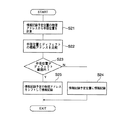
物理アドレスはディスク上の絶対番地を示し、その物理アドレスを元に、システムコントロールMPU40によって、ディスク半径方向の位置すなわち半径位置を計算する(S21)。そして、システムコントロールMPU40は、計算した半径位置と前記ディフェクト位置の概略アドレスを比較して、物理アドレスがディフェクト範囲か否かを判定する(S22、S23)。
【0080】
もし半径位置がディフェクト範囲内であれば、情報記録予定の物理アドレスを、ディフェクトが存在しない位置にシフトして、シフト先の物理アドレスにシークをし記録動作をする(S25)。
【0081】
又、上記ステップS23において、上記半径位置がディフェクト範囲内である場合、情報記録予定の物理アドレスを、欠陥セクタに対して予め決めた交代領域にシフトしして情報記録しても良い。
【0082】
この欠陥セクタに対する交代領域は、本来、ディフェクト有無にかかわらず、情報記録をしている時に、例えば記録ベリファイの結果、ECC訂正不能エラーなどで記録情報の保障ができない場合の情報記録交代領域である。記録不能の原因は、例えばディスク記録面の繰り返し記録による劣化や、ディフェクトの存在などが考えられる。なお、例えば、DVD−RAMのメディアは、このような交代領域を有する事が、規格で定められている。交代領域の運用は、そのメディア規格に定められた運用方法で良い。
【0083】
なお、前記の概略ディフェクト範囲が、交代領域に存在する場合もありうる。この場合、交代セクタエリアをシフトするような処理をしても良く、これもまた、メディア規格に定められた運用方法をもちいて良い。
【0084】
次に本発明の第9の実施形態を説明する。上記ディフェクト位置概略アドレスの検出を行った場合に、概略アドレスで認識されるディフェクト範囲に対して、情報再生を行わないようにシステムコントロールしても良い。その手順例を図18のフローチャートを参照して以下記述する。
【0085】
情報再生を行う場合に、ディスク上の情報再生予定位置の物理アドレスに対応するディスク半径位置と、ディフェクト概略アドレスで示されるディフェクト範囲を前述したように比較する(S31、S32)。
【0086】
もし半径位置がディフェクト範囲内であれば、再生不能を警告手段41に警告して、再生動作を停止する(S33、S35)。この時、製品仕様によっては、ディフェクト範囲外にシークをして、そこから再生するように操作しても良い。
【0087】
また、単に再生しないのではなく、ディフェクト部においてのみサーボ系または信号処理系のゲインなどを調整して再生する構成とすることも可能である。
【0088】
次に本発明の第10の実施形態を説明する。第1〜第3の実施形態のように検出したディフェクト範囲について、その詳細アドレスを検出することもできる。以下、第1の実施形態に係る図1の構成によりディフェクトを検出し、該ディフェクトの詳細物理アドレスを検出する手順を説明する。
【0089】
なお、下記でディフェクト開始位置と定義している位置は図19に示すD1のような位置であり、ディフェクト終了位置と定義している位置については、図19に示すD2のような位置である。
【0090】
図20はディスク内周側から外周側へピックアップ4を移動し、ディフェクト開始位置を検出し、その詳細物理アドレスを求める処理を示すフローチャートである。
【0091】
ピックアップ4をフォワード方向へのフィードキック途中で、ディフェクト検出部20がディフェクト有りを検出した場合(S41、S42)、ディフェクト検出部20はシステム制御MPU40に対してディフェクト有りのステイタスを発行する。
【0092】
システム制御MPU40は、フィードキックの停止を命令し、フィードキック停止後に、ディフェクト検出部20に対して、ディスク一周分のディフェクト検出を再び命令する(S43、S44)。これは、フィードキック中にディフェクトを検出したときのピックアップ4の位置と、実際に停止した位置が異なることがあるからである。
【0093】
次のステップS45でディフェクトがあった場合には、バックワード方向に低速のフィードキックをしながら、ディスク一周毎のディフェクト有無を判定し、ディスク一周中にディフェクトが無いところでフィードキックを停止してトラッキングサーボをオンする(S50〜S54)。
【0094】
ステップS45でディフェクトが無かった場合には、フォワード方向に低速のフィードキックをしながら、ディスク一周毎のディフェクト有無を判定し、ディスク一周中にディフェクトが有るところでフィードキックを停止する(S46〜S49)。そして、バックワード方向に再度低速のフィードキックをしながら、ディスク一周毎のディフェクト有無を判定し、ディスク一周中にディフェクトが無いところでフィードキックを停止してトラッキングサーボをオンする(S50〜S54)。
【0095】
トラッキングサーボオン後の処理を以下に示す。先ずシステム制御MPU40は、アドレスデコード部29よりディスク上の物理アドレスを検出しながら、FO.OK判定部31によりフォーカスサーボの状態、又はTRK.OK判定部32によりトラッキングサーボの状態、またはRF.OK判定部31によりRF信号の状態を検出する事により、ディフェクトを検出する(S54、S55)。
【0096】
このディフェクト検出は、前述した実施形態に示すものとは異なり、従来のトラッキングサーボオン時のディフェクト検出方法を用いる。
【0097】
例えば、トラッキングエラー信号のバンドパスフィルタ通過後のショック検出をする方法、同様にフォーカスエラー信号のバンドパスフィルタ通過後のショック検出をする方法、同様にRFレベル検出結果のバンドパスフィルタ後のショック検出をする方法、等が適用できる。
【0098】
システム制御MPU40は物理アドレスを読むと共に、トラッキングサーボオン時のディフェクトを監視し、ディスク一周を見る。そして、その一周でのトラッキングサーボオン時のディフェクト検出結果によるディフェクト有無を確認し、ディフェクトが無い場合には、フォワードにnトラックキックする(S55〜S57)。ここでnトラックのnは、例えば10トラック程度が適当と思われるが、この数字はシステム仕様や、ディスク種類によって適当に決めて良い。また、ディフェクトの影響を受けずに正確にnトラックキックするために、このnトラックキックを行う位置を、例えば図22のように、トラッキングオフ再生時に既に検出しているディフェクトを避ける位置としても良い。
【0099】
上記のように、ディスク一周のトラッキングオン再生時におけるディフェクト検出(S55)と、ディフェクト無しの場合にフォワード方向にnトラックキックを行うステップ(S57)を繰り返し、ディスク一周のトラッキングオン再生時でディフェクトが有る、と判定された場合(ステップS55でYESの場合)には次のステップに移る。
【0100】
システム制御MPU40は、ディスク再生のデータ信号をデコードしたアドレスデコード部29の物理アドレスを読み取り、同時にディスクのトラッキングオン再生時のディフェクト検出を行う(S58、S59)。そして、トラッキングオン再生時のディフェクトが有ることを検出したら、ディフェクト検出直前の物理アドレス(ステップS58で読み込んだアドレス)を記憶する(S60)。そして、ディスク一周を再生し、一周内にディフェクトがあった場合は、2トラックキックバックを行い(S61、S62)、トラッキングオンし1トラックフォワード側のトラックで、再度、物理アドレスの読み取りと、トラッキングオン再生時のディフェクト検出を行う。
【0101】
2トラックキックバックとトラッキングオン再生との軌跡を図23に示す。ステップS59でディフェクトを検出した後、1トラック内側のトラックのディフェクトを検出し、2トラックキックバック及びトラッキングオン再生で、ディフェクト直前の物理アドレスを記憶し、この動作を繰り返す。このキックバック処理は図22で説明したように、トラッキングオフ再生時に既に検出しているディフェクト位置を避けるようにしても良い。
【0102】
上記のステップは、一周のトラッキングオン再生で、トラッキングオン時のディフェクトが検出されなくなるまで行う。そして、一周のトラッキングオン再生でのディフェクトが無いと検出したら(ステップS63でYESの場合)、一周前のトラッキングオン再生でディフェクト検出される直前の物理アドレスを、ディフェクト開始位置の詳細物理アドレスとしてシステム制御MPUが記憶し(S64)、次のステップに移る。
【0103】
ディフェクト開始位置の詳細物理アドレスを記憶した後の処理を図21に示す。図21はディスク内周側から見たディフェクト終了位置を検出し、その詳細物理アドレスを求める処理を示すフローチャートである。システム制御MPU40は、前記図21の処理で、ディフェクト開始位置の詳細アドレスを検出後に、トラッキングオフし、フォワード方向へのフィードキックを行う(S71)。
【0104】
フォワード方向へのフィードキック途中で、ディフェクト検出部20でディスク一周でのディフェクトが検出されなかった場合(S72)、ディフェクト検出部20は、システム制御MPUに対してディフェクト領域を抜けた意味のステイタスを発行する。
【0105】
システム制御MPU40は、フィードキックを停止を命令し、フィードキック停止後に、確認のためディフェクト検出部20に対して、ディスク一周分のディフェクト検出を再び命令する(S73、74)。ここで、ディフェクトの有無により処理の分岐が異なる。
【0106】
上記でディフェクトがあった場合には、フォワード方向に低速のフィードキックをしながら、ディスク一周毎のディフェクト有無を判定し、ディスク一周中にディフェクトが無いところでフィードキックを停止してトラッキングサーボをオンする(S80〜S84)。
【0107】
ステップ75でディフェクトが無かった場合には、バックワード方向に低速のフィードキックをしながら、ディスク一周毎のディフェクト有無を判定し、ディスク一周中にディフェクトが有るところでフィードキックを停止する(S76〜79)。そして、フォワード方向に再度低速のフィードキックをしながら、ディスク一周毎のディフェクト有無を判定し、ディスク一周中にディフェクトが無いところでフィードキックを停止してトラッキングサーボをオンする(S80〜S84)。
【0108】
トラッキングサーボオン後の処理を以下に示す。先ずシステム制御MPU40は、アドレスデコード部29よりディスク上の物理アドレスを検出しながら、FO.OK判定部31によりフォーカスサーボの状態、又はTRK.OK判定部32によりトラッキングサーボの状態、またはRF.OK判定部31によりRF信号の状態を検出する事により、ディフェクトを検出する(S84、S85)。
【0109】
前述したように、このディフェクト検出は上記実施形態に示したディフェクト検出部20によるものとは異なり、従来のトラッキングサーボオン時のディフェクト検出方法を用いる。
【0110】
システム制御MPU40は物理アドレスを読むと共に、トラッキングサーボオン時のディフェクトを監視し、ディスク一周を見る。そして、その一周でのトラッキングサーボオン時のディフェクト検出結果によるディフェクト有無を確認し、ディフェクトが無い場合には、バックワードにnトラックキックバックする(S85〜S87)。ここでnトラックのnは、例えば10トラック程度が適当と思われるが、この数字はシステム仕様や、ディスク種類によって適当に決めて良い。また、ディフェクトの影響を受けずに正確にnトラックキックバックするために、このnトラックキックを行う位置を、例えば図22のように、トラッキングオフ再生時に既に検出しているディフェクトを避ける位置としても良い。
【0111】
上記のように、ディスク一周のトラッキングオン再生時におけるディフェクト検出(S85)と、ディフェクト無しの場合にバックワード方向にnトラックキックバックを行うステップ(S87)を繰り返し、ディスク一周のトラッキングオン再生時でディフェクトが有る、と判定された場合(ステップS85でYESの場合)には次のステップに移る。
【0112】
システム制御MPU40は、ディスク再生のデータ信号をデコードしたアドレスデコード部29の物理アドレスを読み取り、同時にディスクのトラッキングオン再生時のディフェクト検出を行う(S88、S89)。そして、トラッキングオン再生時のディフェクトが有ることを検出したら、ディフェクト検出直前の物理アドレス(ステップS88で読み込んだアドレス)を記憶する(S90)。そして、ディスク一周を再生し、一周内にディフェクトがあった場合は、次のトラックをオントラック再生し、再度、物理アドレスの読み取りと、トラッキングオン再生時のディフェクト検出を行う。
【0113】
上記のステップは、一周のトラッキングオン再生で、トラッキングオン時のディフェクトが検出されなくなるまで行う。そして、一周のトラッキングオン再生でのディフェクトが無いと検出したら(ステップS92でYESの場合)、一周前のトラッキングオン再生でディフェクト検出される直前の物理アドレスを、ディフェクト終了位置の詳細物理アドレスとしてシステム制御MPUが記憶し、図20の処理に戻る。
【0114】
上記図20、21の各処理フローを繰り返し行い、同時に検出した物理アドレスとフィードキック移動距離との関係により、ディスク最外周の位置に相当する場所を判断し、詳細ディフェクト位置の物理アドレス検出を終了する。
【0115】
製品仕様によっては、上記結果を元に、例えば無効トラックの容量を算出し、製品ユーザーに対する容量低下量の警告などをしても良い。
【0116】
またディフェクト範囲物理アドレスと概記録情報の物理アドレスとの関係で、概記録情報ファイルの再生に支障ある可能性のあるファイル名を警告する等しても良い。
【0117】
いずれの場合でも、製品ユーザーに対して、ディスククリーニングを促すような警告をしても良い。
【0118】
次に本発明の第11の実施形態を説明する。上記第9及び10の実施形態のように、ディフェクト位置詳細物理アドレスの検出を行った場合に、物理アドレスで認識されるディフェクト範囲に対して、情報の記録または再生を行わないようにシステムコントロールしても良い。
【0119】
この第11の実施形態では、先ず情報記録を行う場合に、ディスク上の情報記録予定位置の物理アドレスと、ディフェクト範囲の物理アドレスを比較し、情報記録予定位置がディフェクト範囲内であれば、情報記録予定位置を、ディスク上のディフェクト範囲外にシフトする処理を行う。
【0120】
また、DVD−RAMのようなディスク構造の場合、記録領域の欠陥セクタを代替する領域である、交代領域が存在する。この欠陥セクタに対する交代領域は、ディスク有無にかかわらず、情報記録をしている時に、例えば記録ベリファイの結果、ECC訂正不能エラーなどで記録情報の保障ができない場合の情報記録交代領域である。記録不能の原因は、例えばディスク記録面の繰り返し記録による劣化や、ディフェクトの存在などが、考えられる。なお、このような交代領域は、例えば、DVD−RAMのメディアは、交代領域を有する事が、規格で定められている。交代領域の運用は、そのメディア規格に定められた運用方法で良い。
【0121】
情報記録ディスクが元々このような交代領域を持つ場合、情報記録予定の物理アドレスを、欠陥セクタに対する予め定めた交代領域にシフトして、情報記録するような処理としても良い。
【0122】
なお、前記の概略ディフェクト範囲が、交代領域に存在する場合もありうる。この場合、交代セクタエリアをシフトするような処理をしても良く、これもまた、メディア規格に定められた運用方法をもちいて良い。
【0123】
また、前記のディフェクト位置を表す物理アドレスの検出を行った場合に、物理アドレスで認識されるディフェクト範囲に対して、情報再生を行わないようにシステムコントロールしても良い。その手順を以下に示す。
【0124】
情報記録を行う場合に、ディスク上の情報再生予定位置ファイルブロックの物理アドレス範囲と、ディフェクト範囲を表す物理アドレス範囲を比較する。
【0125】
情報再生予定位置ファイルブロックの物理アドレス範囲に対応する半径位置が、ディフェクト範囲内であれば、再生不能を警告手段41に警告して、再生動作を停止する。この時、製品仕様によっては、ディフェクト範囲外にシークをして、そこから再生するように操作をしても良い。
【0126】
次に本発明の第12の実施形態を説明する。第12の実施形態では、図9を参照して説明した第3の実施形態による処理を実施する場合に、レーザーダイオード光の波長を切りかえ、焦点距離を変更してフォーカスをディスク表面に調節する操作が行なわれる。
【0127】
図24に示すように、フォーカスサーボを行うにあたり、レーザーダイオード光の波長を切りかえることにより、照射ビームのスポット径と、ディスク及びレンズ間の焦点距離が異なってくる。
【0128】
例えば、ディフェクト検出中に、ディフェクトによるフォーカスサーボ外乱の影響で、レンズがディスク面に衝突する可能性を考慮して、レーザーダイオード光の波長が長い光学系に切り替えて、第3の実施形態による処理を実行する。
【0129】
また、例えばビームスポット径を大きくし、ディフェクト検出精度を向上させる目的で、レーザーダイオード光の波長が長いものに、切り替えて、第3の実施形態による処理を実行しても良い。
【0130】
次に本発明の第11の実施形態を説明する。図1の第1の実施形態もしくは図9の第3の実施形態による処理を実施する場合に、ディスク表面に対するフォーカスサーボのサーボはずれを検出する処理と、ディフェクト検出する処理を併用する方法を用いても良い。
【0131】
図25はフォーカスサーボはずれを検出する構成の一例、図26はフォーカスはずれ検出信号のタイミングを表す。
【0132】
図25のように、フォーカスエラー信号25Aの、バンドパスフィルタ33通過後の信号25Bを、2つのスライスSL1とSL2を各閾値とする2系統のコンパレータ34、35でスライスし、各スライス結果をオアゲート36で論理加算した結果が、フォーカスサーボホールド信号25Cとして検出される。このフォーカスサーボホールド信号25Cは、ディフェクトなどによる、フォーカスエラー信号の大きなレベル変動に対して、フォーカス制御が追従せずに直流ホールドする為のタイミング信号である。
【0133】
直流ホールド信号25Eは、フォーカスエラー信号25Aがローパスフィルタ37を通過して得られる信号25Dを、サンプルホールド38によりホールドした結果得られる信号である。この直流ホールド信号25Eのサンプルホールドクロックは、フォーカスサーボホールド信号25Cとサンプルクロック25GをORゲート39でOR演算した結果得られるサンプルクロック25Hである。
【0134】
従ってサンプルホールド38は、フォーカスサーボホールド信号25C発生直後にはサンプルホールドを停止し、フォーカスエラー正常時の直流値をホールドする。そして、フォーカスエラー25Aと、直流ホールド信号25Eを、インバータ47、トランスファーゲート48、49を用いて、フォーカスサーボホールド信号25Cのレベルに応じて切りかえて、フォーカスイコライザ6に入力することにより、フォーカスサーボホールドを行っている。
【0135】
フォーカスはずれ検出部50は、フォーカスサーボホールド信号25Cのパルス幅が、あらかじめ定められた幅WFO以上である場合に、フォーカスはずれであると判定するような処理を行い、フォーカスはずれ信号25Fを生成する。フォーカスはずれ信号25Fは、フォーカスイコライザ6に入力される。フォーカスイコライザ6は、フォーカスはずれ信号を検出したら、例えば、ピックアップヘッドのレンズがディスク面に衝突することを防止する為に、レンズをディスクから退避するような制御信号を出力する。以上のプロセスで、結果的に、25Iのようなフォーカス駆動信号が生成される。
【0136】
本実施形態の場合、図1の第1の実施形態もしくは図9の第3の実施形態によるディフェクト検出を行っている時に、ディフェクトなどの影響で、上記フォーカス外れが検出された場合には、フォワード方向へのフィードキックを所定距離行った後に、フィードキックを停止し、フォーカスサーボをリトライする処理を行う。
【0137】
また、上記のフォーカスはずれ検出は、フォーカスエラーの外乱情報を元に行っても良いが、上記第1もしくは第3の実施形態によるディフェクト検出を行っている場合に、ディフェクト有り検出時にただちにフォーカスサーボをオフし、レンズをディスク面から退避し、所定距離のフィードキックを行い、リトライ動作を再開するような処理としても良い。この場合、25Cのフォーカスサーボホールド信号の代わりに、SW1を制御してディフェクト検出信号を用いても良いし、25Fのフォーカスはずれ検出信号の代わりに、SW2を制御してディフェクト検出信号を用いても良い。
【0138】
【発明の効果】
以上説明したように本発明によれば、非常に短時間でディスク全面のディフェクト検査が可能となり、情報記録不具合を未然に防ぐことができ、ユーザーフレンドリーな光ディスク情報記録再生装置を提供できる。
【図面の簡単な説明】
【図1】本発明の第1の実施形態に係る記録再生装置の構成を示すブロック図。
【図2】本実施形態の動作を示すフローチャート。
【図3】図1の信号1A〜1Dの波形を示す図。
【図4】ディフェクト面積の計算を説明するための図。
【図5】第2の実施形態に係る記録再生装置の構成を示すブロック図。
【図6】第2の実施形態に係るフォトディテクタ周辺の構成を示す図。
【図7】ディフェクト検出信号を説明するための波形図。
【図8】第2の実施形態に係るディフェクト面積の計算を説明するための図。
【図9】第3の実施形態に係る記録再生装置の構成を示すブロック図。
【図10】フォーカスサーボ目標点を示す図。
【図11】第3の実施形態に係るフォトディテクタ周辺の構成を示す図。
【図12】第3の実施形態に係るフォディフェクト検出信号を説明するための波形図。
【図13】第3の実施形態に係るフォディフェクト面積の計算を説明するための図。
【図14】第4及び第5の実施形態に係る記録再生装置の構成を示すブロック図。
【図15】第6の実施形態に係る記録再生装置の構成を示すブロック図。
【図16】第7の実施形態に係る記録再生装置の構成を示すブロック図。
【図17】第8の実施形態の動作を説明するフローチャート。
【図18】第9の実施形態の動作を説明するフローチャート。
【図19】光ディスク上のディフェクト開始位置終了位置を説明するための図。
【図20】ディフェクト開始位置を検出し、その詳細物理アドレスを求める処理を示すフローチャート。
【図21】ディフェクト終了位置を検出し、その詳細物理アドレスを求める処理を示すフローチャート。
【図22】nトラックキックを行う位置を示す図。
【図23】2トラックキックバック及びトラッキングオン再生の軌跡を示す図。
【図24】レーザーダイオード光の波長に応じて、照射ビームのスポット径と、ディスク及びレンズ間の焦点距離が異なる様子を示す図。
【図25】フォーカスサーボはずれを検出する構成の一例。
【図26】フォーカスはずれ検出信号のタイミングを表す図。
【符号の説明】
1…光ディスク、2…スピンドルモータ、3…送りモータ、4…光ピックアップ、5…RFアンプ、7、9、14、16…アンプ、17…ディスク回転周波数制御部、42…LED、44…ミラー、47…ハーフプリズム。[0001]
BACKGROUND OF THE INVENTION
The present invention relates to an optical disc recording / reproducing apparatus that records and reproduces information on an optical disc, and more particularly to an optical disc recording / reproducing apparatus that detects a defect portion such as dirt or scratches on an optical disc.
[0002]
[Prior art]
In an optical disk recording / reproducing apparatus, if there is a defect such as dirt or scratches on the disk, tracking servo and further focus servo may not be possible, and information may not be recorded or reproduced on the defect portion.
[0003]
Conventionally, as a method for detecting a defect over the entire surface of an optical disk, there are the following techniques. The first method is to perform track seek at M locations, perform tracking-on reproduction for N laps, and detect a defect on the entire disk surface.
[0004]
As a second method, as disclosed in JP-A-6-203466, the track count kick, that is, the optical pickup is moved at high speed by N tracks, and the difference between the number of tracks crossed at that time and the tracking on address, that is, the track count kick There is a method for detecting a defect based on a difference from the number of tracks obtained from a difference in addresses read by tracking-on reproduction before and after the recording.
[0005]
[Problems to be solved by the invention]
In the first method of performing track seek for the M locations, it is necessary to repeat seek for each zone of the disc and tracking-on reproduction operation for one or more rounds, and it takes time to detect defects on the entire surface of the disc. For this reason, it is difficult to achieve product specifications that always perform a defect inspection every time a disc is inserted.
[0006]
In the second method, since tracking-on reproduction is required before and after the track count kick operation and the physical address must be decoded, the procedure is complicated. Also, it does not take into account the abnormal operation when tracking is turned on on the defect.
[0007]
Accordingly, an object of the present invention is to provide an optical disc recording / reproducing apparatus capable of detecting defects over the entire surface of an optical disc in a short time and preventing information recording problems.
[0008]
[Means for Solving the Problems]
In order to achieve the above object, in the optical disk recording / reproducing apparatus of the present invention, the main control means causes the focus control means, the feed control means, and the rotation speed control means to execute the control without performing the tracking control by the tracking control means. The defect determination means compares the peak value of the tracking error signal obtained from the light receiving element that receives the laser beam reflected from the optical disc with a reference threshold value, so that the laser beam irradiates the defect portion on the optical disc. Judge whether you are doing.
[0009]
In general, the reflected light level of an optical disk is lower when reflecting a defect portion than when reflecting a normal disk surface. Therefore, the defect determination means determines that there is a defect when the peak value of the tracking error signal is lower than a predetermined reference threshold.
[0010]
In general, the tracking error signal has a lower amplitude level when a laser beam irradiates an unrecorded part than when a laser beam irradiates an information recording part of an optical disk. Accordingly, different reference thresholds are applied when the laser beam irradiates the information recording portion and when the laser recording portion irradiates the unrecorded portion.
[0011]
Further, as the reflected light level, a reflected light amount obtained from a light receiving element that receives LED light reflected from the optical disk can be used. Further, the amplitude value of the focus error signal obtained in a state where the focus of the laser beam is controlled on the surface of the disk can be used as the reflected light level. Therefore, during the defect detection process, it is difficult to accompany the run-up of the pickup servo due to an abnormal disk surface.
[0012]
In the optical disk recording / reproducing apparatus of the present invention, the area of the defect portion on the optical disk is obtained based on the rotation period of the optical disk, the movement amount of the pickup, and the defect determination result by the defect determination means. As a result, a defect detection function is provided that immediately detects (in about 1 to 2 seconds) dirt and scratches on the entire disk surface. When a defect is detected on the disc, the user is warned to that effect together with the area of the defect portion.
[0013]
DETAILED DESCRIPTION OF THE INVENTION
Hereinafter, embodiments of the present invention will be described in detail with reference to the drawings.
[0014]
FIG. 1 is a block diagram showing a configuration of a recording / reproducing apparatus according to the first embodiment of the present invention. The information recording / reproducing
[0015]
The optical pickup 4 records and reproduces information on the
[0016]
The
[0017]
The
[0018]
The
[0019]
The
[0020]
A system control MPU 40 (main control means) comprehensively controls the optical disc recording / reproducing apparatus via a control bus.
[0021]
Next, the operation of this embodiment will be described. FIG. 2 is a flowchart showing the operation of this embodiment. The
[0022]
Thereafter, the
[0023]
The
[0024]
The TE
[0025]
The state of determination is shown in FIG. The signals shown in FIGS. 3A to 3D correspond to the
[0026]
Here, it is assumed that the normal value of the tracking error peak value varies depending on whether or not the reflectivity of the disk is a data-recorded area, and the threshold value th in FIG. L And th H As described above, the peak detection threshold is switched depending on the presence or absence of data. In this example, the threshold switching procedure is described for the case where the reflectance decreases in the data recorded area and the peak value of the tracking error decreases. 3A and 3B, the high level indicates a recorded area, and the low level indicates an unrecorded area. The level of the
[0027]
The defect
[0028]
When the pickup 4 reaches the end of the area where defect detection is to be performed (S7), the
[0029]
When a warning is given to the product user, the approximate defect area value calculated by the method shown in FIG. 4 may be displayed to the user simultaneously with the warning. Further, a warning may be given to the product user to encourage disc cleaning.
[0030]
In the above description, the area where defect detection is to be performed is determined using the TAC signal from the feed
[0031]
Next, a second embodiment of the present invention will be described. FIG. 5 is a block diagram showing a configuration of a recording / reproducing apparatus according to the second embodiment. First, the
[0032]
After that, as in the first embodiment, the
[0033]
The
[0034]
FIG. 6 shows the determination mechanism. As shown in FIG. 6A, the LED light emitted from the
[0035]
FIG. 7 shows the state of defect detection. As shown in FIG. 7A, the reflected
[0036]
The defect
[0037]
When the optical pickup 4 reaches the end position of the area where defect detection is to be performed, the
[0038]
The
[0039]
Further, when a plurality of optical systems are provided so as to correspond to a plurality of standard discs, it is desirable to use an optical system with a light source having the longest wavelength.
[0040]
Next, a third embodiment of the present invention will be described. FIG. 9 is a block diagram showing a configuration of a recording / reproducing apparatus according to the third embodiment. First, the
[0041]
Next, as in the first embodiment, the
[0042]
When the pickup 4 reaches the area where the defect detection is to be performed, the system control MPU instructs the
[0043]
The determination mechanism is shown in FIG. As shown in FIG. 11A, the laser light emitted from the
[0044]
FIG. 12 shows the state of defect detection. As shown in FIG. 12A, the reflected
[0045]
The defect
[0046]
When the optical pickup 4 reaches the end position of the area where defect detection is to be performed, the
[0047]
Next, a fourth embodiment of the present invention will be described. In the fourth embodiment, when the operation according to the first embodiment is executed, a rough defect position address is detected using a track count signal obtained by binarizing the tracking error TE signal in FIG.
[0048]
FIG. 14 is a block diagram showing a configuration of a recording / reproducing apparatus according to the fourth embodiment. First, as described above, the
[0049]
Thereafter, the
[0050]
The
[0051]
When a defect is detected by the TE
[0052]
Similarly, the approximate address of the defect end position can be detected from the track count value immediately after passing through the defect end position. Each approximate address is stored in the defect approximate address determination unit 26.
[0053]
When the number of feed kick pulses reaches the end position of the area where defect detection is to be performed, the system control MPU outputs a command to end the defect detection to the system as described above, stops the feed kick, and sets the defect approximate address to the defect. Read from the general address detector 26. Based on the result, a warning is given to the system control or product user.
[0054]
Next, a fifth embodiment of the present invention will be described. There may be a case where the track count is lost due to a defect. Therefore, in this embodiment, the defect address is obtained by using both the TAC pulse count which is an encoder signal provided in the transfer means of the optical pickup and the track count.
[0055]
The configuration of the recording / reproducing apparatus according to the fifth embodiment is the same as that of the fourth embodiment shown in FIG. First, the
[0056]
Thereafter, the
[0057]
When the pickup 4 reaches an area where the defect detection is to be performed, the
[0058]
When a defect is detected by the
[0059]
Similarly, the approximate address of the defect end position can be detected from the TAC count value and the track count value immediately after passing the defect end portion. Each approximate address is stored in the defect approximate
[0060]
When the number of feed kick pulses reaches the end position of the area where defect detection is to be performed, the
[0061]
With respect to the track count value, there may be a count loss due to the influence of the defect, but the approximate address of the defect position can be estimated although there is a possibility of occurrence of a count error less than the TAC pulse length.
[0062]
Next, a sixth embodiment of the present invention will be described. In the above embodiment, the
[0063]
FIG. 15 is a block diagram showing a configuration of a recording / reproducing apparatus according to the sixth embodiment. First, the
[0064]
Thereafter, the
[0065]
When the pickup 4 reaches an area where the defect detection is to be performed, the
[0066]
When defect detection is performed by the
[0067]
Similarly, the approximate address of the defect end position can be detected from the TAC count value and the timer value immediately after passing the defect end portion. Each approximate address is stored in the defect approximate
[0068]
When the pickup 4 reaches the end position of the area where defect detection is to be performed, the
[0069]
In the fifth and sixth embodiments, the count values of both the
[0070]
Next, a seventh embodiment of the present invention will be described. The counting means constituted by the
[0071]
FIG. 16 is a block diagram showing a configuration of a recording / reproducing apparatus according to the seventh embodiment. First, the
[0072]
Thereafter, the
[0073]
When the pickup 4 reaches an area where the defect detection is to be performed, the
[0074]
When the defect is detected by the
[0075]
Similarly, the approximate address of the defect end position can be determined by storing the timer value immediately after passing the defect end portion. Each approximate address is stored in the defect approximate address determination unit 26c.
[0076]
When the pickup 4 reaches the end position of the area where defect detection is to be performed, the
[0077]
Next, an eighth embodiment of the present invention will be described. When the defect position approximate address is detected, the system control may be performed so that information recording is not performed on the defect range recognized by the approximate address. An example of the procedure will be described below with reference to the flowchart of FIG.
[0078]
When performing information recording, the physical address of the information recording scheduled position on the disc is compared with the defect range indicated by the defect approximate address. The comparison method is as follows.
[0079]
The physical address indicates an absolute address on the disk, and the position in the disk radial direction, that is, the radial position is calculated by the
[0080]
If the radial position is within the defect range, the physical address scheduled to be recorded is shifted to a position where no defect exists, and the seek is performed to the physical address of the shift destination to perform the recording operation (S25).
[0081]
In step S23, when the radius position is within the defect range, information recording may be performed by shifting the physical address to be recorded of information to a predetermined replacement area for the defective sector.
[0082]
The replacement area for the defective sector is originally an information recording replacement area when information is recorded regardless of the presence or absence of defects, for example, when recording information cannot be guaranteed due to an ECC uncorrectable error as a result of recording verification. . Possible causes of recording failure include, for example, deterioration due to repeated recording on the disk recording surface, presence of defects, and the like. For example, it is defined in the standard that a DVD-RAM medium has such a replacement area. The operation of the alternate area may be the operation method defined in the media standard.
[0083]
The approximate defect range may exist in the replacement area. In this case, a process for shifting the alternate sector area may be performed, and this may also use the operation method defined in the media standard.
[0084]
Next, a ninth embodiment of the present invention will be described. When the defect position approximate address is detected, the system may be controlled so that information is not reproduced for the defect range recognized by the approximate address. An example of the procedure will be described below with reference to the flowchart of FIG.
[0085]
When performing information reproduction, the disk radius position corresponding to the physical address of the information reproduction scheduled position on the disk is compared with the defect range indicated by the defect approximate address as described above (S31, S32).
[0086]
If the radial position is within the defect range, the warning means 41 is warned that the reproduction is impossible, and the reproduction operation is stopped (S33, S35). At this time, depending on the product specifications, seek may be performed outside the defect range, and playback may be performed from there.
[0087]
Further, it is possible to adopt a configuration in which reproduction is performed not by simply reproducing, but by adjusting the gain of the servo system or signal processing system only at the defect portion.
[0088]
Next, a tenth embodiment of the present invention will be described. It is also possible to detect the detailed address of the detected defect range as in the first to third embodiments. A procedure for detecting a defect with the configuration of FIG. 1 according to the first embodiment and detecting a detailed physical address of the defect will be described below.
[0089]
The position defined as the defect start position below is a position such as D1 shown in FIG. 19, and the position defined as the defect end position is a position such as D2 shown in FIG.
[0090]
FIG. 20 is a flowchart showing a process of moving the pickup 4 from the inner circumference side of the disc to the outer circumference side, detecting the defect start position, and obtaining its detailed physical address.
[0091]
When the
[0092]
The
[0093]
If there is a defect in the next step S45, the low-speed feed kick is performed in the backward direction, and the presence / absence of the defect is determined every round of the disk. The servo is turned on (S50 to S54).
[0094]
If there is no defect in step S45, it is determined whether or not there is a defect for each round of the disk while performing a low speed feed kick in the forward direction, and the feed kick is stopped when there is a defect in the round of the disk (S46 to S49). . Then, while performing a low-speed feed kick in the backward direction again, the presence / absence of a defect is determined for each round of the disk, and when there is no defect in the round of the disk, the feed kick is stopped and the tracking servo is turned on (S50 to S54).
[0095]
The processing after the tracking servo is turned on is shown below. First, the
[0096]
This defect detection is different from that shown in the above-described embodiment by using a conventional defect detection method when the tracking servo is on.
[0097]
For example, a method for detecting a shock after passing a bandpass filter for a tracking error signal, a method for detecting a shock after passing a bandpass filter for a focus error signal, and a shock detection after a bandpass filter for an RF level detection result. The method of doing, etc. can be applied.
[0098]
The
[0099]
As described above, the defect detection (S55) at the time of tracking-on reproduction of one round of the disk and the step (S57) of performing an n-track kick in the forward direction when there is no defect are repeated. If it is determined that there is (YES in step S55), the process proceeds to the next step.
[0100]
The
[0101]
The trajectory between the two-track kickback and tracking-on playback is shown in FIG. After the defect is detected in step S59, the defect of the track inside one track is detected, the physical address immediately before the defect is stored by two-track kickback and tracking-on reproduction, and this operation is repeated. In this kickback process, as described with reference to FIG. 22, the defect position already detected at the time of tracking off reproduction may be avoided.
[0102]
The above steps are performed until tracking-on defects are not detected in one-cycle tracking-on reproduction. If it is detected that there is no defect in one cycle of tracking-on reproduction (YES in step S63), the physical address immediately before the defect is detected in one cycle of tracking-on reproduction is used as the detailed physical address of the defect start position. The control MPU stores it (S64), and proceeds to the next step.
[0103]
FIG. 21 shows the processing after storing the detailed physical address of the defect start position. FIG. 21 is a flowchart showing a process for detecting the defect end position viewed from the inner periphery side of the disk and obtaining the detailed physical address. The
[0104]
In the middle of feed kick in the forward direction, when the
[0105]
The
[0106]
If there is a defect in the above, determine the presence / absence of the defect for each round of the disk while performing a low-speed feed kick in the forward direction, stop the feed kick when there is no defect in the round of the disk, and turn on the tracking servo (S80-S84).
[0107]
If there is no defect in
[0108]
The processing after the tracking servo is turned on is shown below. First, the
[0109]
As described above, this defect detection is different from that performed by the
[0110]
The
[0111]
As described above, the defect detection (S85) at the time of tracking-on playback of one round of the disc and the step (S87) of performing n-track kickback in the backward direction when there is no defect are repeated. If it is determined that there is a defect (YES in step S85), the process proceeds to the next step.
[0112]
The
[0113]
The above steps are performed until tracking-on defects are not detected in one-cycle tracking-on reproduction. If it is detected that there is no defect in one cycle of tracking-on reproduction (YES in step S92), the physical address immediately before the defect is detected in one cycle of tracking-on reproduction is used as the detailed physical address of the defect end position. Control MPU memorize | stores and returns to the process of FIG.
[0114]
20 and 21 are repeated, the location corresponding to the outermost position of the disk is determined based on the relationship between the simultaneously detected physical address and the feed kick movement distance, and the physical address detection of the detailed defect position is completed. To do.
[0115]
Depending on the product specifications, for example, the capacity of the invalid track may be calculated based on the above result to warn the product user of the amount of capacity reduction.
[0116]
Also, a file name that may interfere with the reproduction of the approximate recording information file may be warned based on the relationship between the defect range physical address and the physical address of the approximate recording information.
[0117]
In either case, a warning may be given to the product user to encourage disc cleaning.
[0118]
Next, an eleventh embodiment of the present invention will be described. As in the ninth and tenth embodiments, when the defect position detailed physical address is detected, the system control is performed so that information is not recorded or reproduced in the defect range recognized by the physical address. May be.
[0119]
In the eleventh embodiment, when information recording is first performed, the physical address of the information recording scheduled position on the disc is compared with the physical address of the defect range, and if the information recording planned position is within the defect range, the information A process of shifting the scheduled recording position out of the defect range on the disk is performed.
[0120]
In the case of a disk structure such as a DVD-RAM, there is a replacement area that is an area that replaces a defective sector in the recording area. The replacement area for the defective sector is an information recording replacement area when recording information cannot be guaranteed due to an ECC uncorrectable error, for example, as a result of recording verification, regardless of the presence or absence of a disk. Possible causes of recording failure include, for example, deterioration due to repeated recording on the disk recording surface, presence of defects, and the like. Note that, for example, such a replacement area is defined by the standard that a DVD-RAM medium has a replacement area. The operation of the alternate area may be the operation method defined in the media standard.
[0121]
When the information recording disk originally has such a replacement area, the information recording schedule may be shifted to a predetermined replacement area for the defective sector to record information.
[0122]
The approximate defect range may exist in the replacement area. In this case, a process for shifting the alternate sector area may be performed, and this may also use the operation method defined in the media standard.
[0123]
Further, when the physical address representing the defect position is detected, the system control may be performed so that information is not reproduced for the defect range recognized by the physical address. The procedure is shown below.
[0124]
When recording information, the physical address range of the information reproduction scheduled position file block on the disc is compared with the physical address range representing the defect range.
[0125]
If the radius position corresponding to the physical address range of the information reproduction planned position file block is within the defect range, the warning means 41 is warned that reproduction is impossible, and the reproduction operation is stopped. At this time, depending on the product specifications, it may be possible to seek out of the defect range and perform playback from there.
[0126]
Next, a twelfth embodiment of the present invention will be described. In the twelfth embodiment, when the processing according to the third embodiment described with reference to FIG. 9 is performed, the operation of switching the wavelength of the laser diode light and changing the focal length to adjust the focus to the disk surface. Is done.
[0127]
As shown in FIG. 24, when focus servo is performed, the spot diameter of the irradiation beam and the focal length between the disk and the lens differ by switching the wavelength of the laser diode light.
[0128]
For example, during the defect detection, considering the possibility of the lens colliding with the disk surface due to the influence of the focus servo disturbance due to the defect, switching to the optical system having a long wavelength of the laser diode light, the processing according to the third embodiment Execute.
[0129]
For example, for the purpose of increasing the beam spot diameter and improving the defect detection accuracy, the processing according to the third embodiment may be executed by switching to a laser diode having a long wavelength.
[0130]
Next, an eleventh embodiment of the present invention will be described. When the processing according to the first embodiment of FIG. 1 or the third embodiment of FIG. 9 is performed, a method that uses a process of detecting a servo deviation of the focus servo with respect to the disk surface and a process of detecting a defect is used. Also good.
[0131]
FIG. 25 shows an example of a configuration for detecting a focus servo error, and FIG. 26 shows the timing of a focus error detection signal.
[0132]
As shown in FIG. 25, the
[0133]
The DC hold
[0134]
Therefore, the sample hold 38 stops the sample hold immediately after the focus
[0135]
The focus
[0136]
In the case of this embodiment, when the above-described defocusing is detected due to a defect or the like when performing the defect detection according to the first embodiment of FIG. 1 or the third embodiment of FIG. After performing a feed kick in the direction for a predetermined distance, the feed kick is stopped and the focus servo is retried.
[0137]
Further, the above-mentioned defocus detection may be performed based on the disturbance information of the focus error. However, when the defect detection according to the first or third embodiment is performed, the focus servo is immediately activated when the defect is detected. It is also possible to perform processing such as turning off, retracting the lens from the disk surface, performing a feed kick for a predetermined distance, and restarting the retry operation. In this case, the defect detection signal may be used by controlling SW1 instead of the focus servo hold signal of 25C, or the defect detection signal may be used by controlling SW2 instead of the focus shift detection signal of 25F. good.
[0138]
【The invention's effect】
As described above, according to the present invention, the defect inspection on the entire surface of the disk can be performed in a very short time, an information recording defect can be prevented, and a user-friendly optical disk information recording / reproducing apparatus can be provided.
[Brief description of the drawings]
FIG. 1 is a block diagram showing a configuration of a recording / reproducing apparatus according to a first embodiment of the present invention.
FIG. 2 is a flowchart showing the operation of the embodiment.
FIG. 3 is a diagram illustrating waveforms of
FIG. 4 is a diagram for explaining calculation of a defect area.
FIG. 5 is a block diagram showing a configuration of a recording / reproducing apparatus according to a second embodiment.
FIG. 6 is a diagram showing a configuration around a photodetector according to a second embodiment.
FIG. 7 is a waveform diagram for explaining a defect detection signal.
FIG. 8 is a view for explaining calculation of a defect area according to a second embodiment.
FIG. 9 is a block diagram showing a configuration of a recording / reproducing apparatus according to a third embodiment.
FIG. 10 is a diagram showing a focus servo target point.
FIG. 11 is a diagram showing a configuration around a photodetector according to a third embodiment.
FIG. 12 is a waveform diagram for explaining a ffect detection signal according to a third embodiment.
FIG. 13 is a view for explaining calculation of a flawed area according to a third embodiment.
FIG. 14 is a block diagram showing a configuration of a recording / reproducing apparatus according to fourth and fifth embodiments.
FIG. 15 is a block diagram showing the configuration of a recording / reproducing apparatus according to a sixth embodiment.
FIG. 16 is a block diagram showing the configuration of a recording / reproducing apparatus according to a seventh embodiment.
FIG. 17 is a flowchart for explaining the operation of the eighth embodiment;
FIG. 18 is a flowchart for explaining the operation of the ninth embodiment;
FIG. 19 is a view for explaining a defect start position end position on an optical disc.
FIG. 20 is a flowchart showing processing for detecting a defect start position and obtaining its detailed physical address.
FIG. 21 is a flowchart showing processing for detecting a defect end position and obtaining its detailed physical address;
FIG. 22 is a diagram showing a position where an n-track kick is performed.
FIG. 23 is a diagram showing a locus of two-track kickback and tracking-on playback.
FIG. 24 is a diagram showing a state in which the spot diameter of the irradiation beam and the focal length between the disk and the lens differ depending on the wavelength of the laser diode light.
FIG. 25 shows an example of a configuration for detecting focus servo deviation.
FIG. 26 is a diagram illustrating the timing of a focus error detection signal.
[Explanation of symbols]
DESCRIPTION OF
Claims (7)
前記光ディスクを回転し、該回転速度を制御する回転速度制御手段と、
前記ピックアップを前記光ディスクの半径方向に移動し、該移動速度を制御するフィード制御手段と、
前記レーザービームのフォーカスが前記ディスク記録面上となるよう前記光ピックアップを制御するフォーカス制御手段と、
前記レーザービームが前記ディスク上のトラックに追随するよう前記光ピックアップを制御するトラッキング制御手段と、
装置を総合的に制御する主制御手段と、
前記主制御手段が、前記トラッキング制御手段によるトラッキング制御を行わずに、フォーカス制御手段、フィード制御手段、回転速度制御手段による制御を実行させている際に、前記光ディスクを反射した前記レーザービームを受光する受光素子から得られるトラッキングエラー信号のピーク値を、基準閾値と比較することにより、前記レーザービームが前記光ディスク上のディフェクト部を照射しているか判断するディフェクト判断手段とを具備し、
前記ディフェクト判断手段は、前記レーザービームが光ディスクの情報記録部を照射しているか未記録部を照射しているか判断する手段を更に具備し、前記レーザービームが前記情報記録部を照射している場合に、前記基準閾値として第1の基準閾値を適用し、前記未記録部を照射している場合に、前記基準閾値として前記第1より大きい第2の基準閾値を適用することを特徴とする光ディスク記録再生装置。An optical pickup that records and reproduces information on an optical disk using a laser beam;
A rotation speed control means for rotating the optical disc and controlling the rotation speed;
Feed control means for moving the pickup in the radial direction of the optical disc and controlling the moving speed;
Focus control means for controlling the optical pickup so that the focus of the laser beam is on the disk recording surface;
Tracking control means for controlling the optical pickup so that the laser beam follows a track on the disk;
Main control means for comprehensively controlling the device;
The main control means receives the laser beam reflected from the optical disc when the control by the focus control means, the feed control means, and the rotation speed control means is executed without performing the tracking control by the tracking control means. A defect determination means for determining whether the laser beam is irradiating a defect portion on the optical disc by comparing a peak value of a tracking error signal obtained from the light receiving element to a reference threshold value,
The defect judging means further comprises means for judging whether the laser beam irradiates an information recording part of an optical disc or an unrecorded part, and the laser beam irradiates the information recording part. In addition, when the first reference threshold is applied as the reference threshold and the unrecorded portion is irradiated, a second reference threshold larger than the first is applied as the reference threshold. Recording / playback device.
前記移動手段により移動された前記ピックアップの移動量を検出する移動量検出手段と、
前記周期検出手段により検出された前記光ディスクの回転周期と、前記移動量検出手段により検出された前記ピックアップの移動量と、前記ディフェクト判断手段によるディフェクト判断結果を元に、前記光ディスク上のディフェクト部の量を検出するディフェクト量検知手段と、
を更に具備することを特徴とする請求項1記載の光ディスク記録再生装置。 Period detecting means for detecting a rotation period of the optical disk rotated by the rotation driving means;
A moving amount detecting means for detecting a moving amount of the pickup moved by the moving means;
Based on the rotation period of the optical disk detected by the period detection unit, the movement amount of the pickup detected by the movement amount detection unit, and the defect determination result by the defect determination unit, the defect portion on the optical disk A defect amount detecting means for detecting the amount;
The optical disc recording / reproducing apparatus according to claim 1 , further comprising:
前記ディフェクト判断手段による判断結果及び前記カウント手段のカウント値から、前記ディフェクト部の概略アドレスを判断するアドレス判断手段と、
前記概略アドレスを記憶する記憶手段と、
を更に具備することを特徴とする請求項1記載の光ディスク記録再生装置。 Using a tracking error signal obtained from a light receiving element that receives the laser beam reflected from the optical disc, and counting means for counting the number of passes of the laser beam through the track on the optical disc;
Address determination means for determining an approximate address of the defect portion from the determination result by the defect determination means and the count value of the counting means;
Storage means for storing the approximate address;
The optical disc recording / reproducing apparatus according to claim 1 , further comprising:
前記ディフェクト判断手段によるディフェクト部検出時の前記タイマー手段の計測結果と、前記ピックアップ移動手段の移動目標速度との関係からディフェクト部の概略アドレスを判断する手段と、
前記概略アドレスを記憶する記憶手段と、
を更に具備することを特徴とする請求項1記載の光ディスク記録再生装置。 Timer means for measuring the elapsed time of the defect judgment operation by the defect judgment means;
Means for judging the approximate address of the defect portion from the relationship between the measurement result of the timer means at the time of detecting the defect portion by the defect judgment means and the movement target speed of the pickup moving means;
Storage means for storing the approximate address;
The optical disc recording / reproducing apparatus according to claim 1, further comprising:
前記ディフェクト判断手段によりディフェクト部が検出されたときの前記移動距離計測手段の計測結果から、前記ディフェクト部の概略アドレスを判断する判断手段と、
前記概略アドレスを記憶する記憶手段と、
を更に具備することを特徴とする請求項1記載の光ディスク記録再生装置。 A moving distance measuring means for measuring a distance traveled by the pickup by the moving means;
Judgment means for judging an approximate address of the defect part from the measurement result of the movement distance measurement means when the defect part is detected by the defect judgment means;
Storage means for storing the approximate address;
The optical disc recording / reproducing apparatus according to claim 1, further comprising:
前記主制御手段は、ディフェクト検出と同時に前記フォーカスサーボ外れ検出手段でフォーカスサーボ外れが検出された時に、フォーカス外れが発生した位置から所定距離の位置に前記ピックアップを移動し、あらためてフォーカスサーボを行い、ディフェクト検出動作を再開するリトライ手段を更に具備することを特徴とする請求項1記載の光ディスク記録再生装置。 The focus control means has focus servo loss detection means,
The main control means moves the pickup to a position at a predetermined distance from the position where the focus loss occurs when the focus servo loss detection means detects the focus servo loss simultaneously with the defect detection, and performs focus servo again, 2. The optical disc recording / reproducing apparatus according to claim 1, further comprising retry means for restarting the defect detection operation .
Priority Applications (1)
| Application Number | Priority Date | Filing Date | Title |
|---|---|---|---|
| JP2001048493A JP3998424B2 (en) | 2001-02-23 | 2001-02-23 | Optical disc recording / reproducing apparatus |
Applications Claiming Priority (1)
| Application Number | Priority Date | Filing Date | Title |
|---|---|---|---|
| JP2001048493A JP3998424B2 (en) | 2001-02-23 | 2001-02-23 | Optical disc recording / reproducing apparatus |
Publications (3)
| Publication Number | Publication Date |
|---|---|
| JP2002251728A JP2002251728A (en) | 2002-09-06 |
| JP2002251728A5 JP2002251728A5 (en) | 2005-03-17 |
| JP3998424B2 true JP3998424B2 (en) | 2007-10-24 |
Family
ID=18909751
Family Applications (1)
| Application Number | Title | Priority Date | Filing Date |
|---|---|---|---|
| JP2001048493A Expired - Fee Related JP3998424B2 (en) | 2001-02-23 | 2001-02-23 | Optical disc recording / reproducing apparatus |
Country Status (1)
| Country | Link |
|---|---|
| JP (1) | JP3998424B2 (en) |
Families Citing this family (2)
| Publication number | Priority date | Publication date | Assignee | Title |
|---|---|---|---|---|
| CN1324582C (en) * | 2004-05-26 | 2007-07-04 | 联发科技股份有限公司 | Automatic CD driver loader recording and reconnecting method |
| CN100495549C (en) | 2005-03-17 | 2009-06-03 | 松下电器产业株式会社 | Optical disc device and its drive method |
-
2001
- 2001-02-23 JP JP2001048493A patent/JP3998424B2/en not_active Expired - Fee Related
Also Published As
| Publication number | Publication date |
|---|---|
| JP2002251728A (en) | 2002-09-06 |
Similar Documents
| Publication | Publication Date | Title |
|---|---|---|
| CN101174434B (en) | Optical recording medium driving device and spherical aberration adjustment method | |
| JP2002117534A (en) | Optical disk reproducing device and kind of disk discriminating method | |
| KR100430249B1 (en) | Apparatus for and method of determining information record medium | |
| JP2004335084A (en) | Discriminating method of recordable disk, and its device | |
| WO2006009082A1 (en) | Optical disk recording/reproduction device and disk determination method for optical disk recording/reproduction device | |
| JP3998424B2 (en) | Optical disc recording / reproducing apparatus | |
| JP4342930B2 (en) | Optical disc apparatus, control method therefor, and recording medium | |
| EP1580736B1 (en) | Optical disc reproduction device and optical disc reproduction method | |
| JP2007265596A (en) | Information recording and reproducing device | |
| JP3975630B2 (en) | Optical disc apparatus and focus control method thereof | |
| KR101607856B1 (en) | Optical disc playback device and control method thereof | |
| US20050174275A1 (en) | Optical disk system with improved playability | |
| JP3854075B2 (en) | Optical disc drive device and optical disc device | |
| JP4192667B2 (en) | Binarization circuit, binarization method, optical disc apparatus | |
| JP3887822B2 (en) | Optical disk playback device | |
| JP2008234831A (en) | Rewritable recording medium | |
| JP2007066484A (en) | Control method of optical disk apparatus, and optical disk apparatus | |
| JP4479750B2 (en) | Optical disc recording / reproducing apparatus | |
| JP4626691B2 (en) | Optical disc apparatus and optical disc discrimination method | |
| JP3953987B2 (en) | Optical disc reproducing method and optical disc reproducing apparatus | |
| JP2009211773A (en) | Optical disk reproducing unit and optical disk reproducing method | |
| JP2009116990A (en) | Method of discriminating optical disk and optical disk device | |
| JP2001126270A (en) | Seek control method and device | |
| JPH11213529A (en) | Disk discriminating device for disk reproducing device | |
| US20080304381A1 (en) | Method and Apparatus for Detecting Cracks in an Optical Record Carrier |
Legal Events
| Date | Code | Title | Description |
|---|---|---|---|
| A521 | Written amendment |
Free format text: JAPANESE INTERMEDIATE CODE: A523 Effective date: 20040422 |
|
| A621 | Written request for application examination |
Free format text: JAPANESE INTERMEDIATE CODE: A621 Effective date: 20040422 |
|
| A977 | Report on retrieval |
Free format text: JAPANESE INTERMEDIATE CODE: A971007 Effective date: 20060925 |
|
| A131 | Notification of reasons for refusal |
Free format text: JAPANESE INTERMEDIATE CODE: A131 Effective date: 20061017 |
|
| A521 | Written amendment |
Free format text: JAPANESE INTERMEDIATE CODE: A523 Effective date: 20061218 |
|
| A131 | Notification of reasons for refusal |
Free format text: JAPANESE INTERMEDIATE CODE: A131 Effective date: 20070508 |
|
| A521 | Written amendment |
Free format text: JAPANESE INTERMEDIATE CODE: A523 Effective date: 20070706 |
|
| TRDD | Decision of grant or rejection written | ||
| A01 | Written decision to grant a patent or to grant a registration (utility model) |
Free format text: JAPANESE INTERMEDIATE CODE: A01 Effective date: 20070731 |
|
| A61 | First payment of annual fees (during grant procedure) |
Free format text: JAPANESE INTERMEDIATE CODE: A61 Effective date: 20070807 |
|
| FPAY | Renewal fee payment (event date is renewal date of database) |
Free format text: PAYMENT UNTIL: 20100817 Year of fee payment: 3 |
|
| LAPS | Cancellation because of no payment of annual fees |