JP3995564B2 - Semiconductor device and manufacturing method thereof - Google Patents
Semiconductor device and manufacturing method thereof Download PDFInfo
- Publication number
- JP3995564B2 JP3995564B2 JP2002253781A JP2002253781A JP3995564B2 JP 3995564 B2 JP3995564 B2 JP 3995564B2 JP 2002253781 A JP2002253781 A JP 2002253781A JP 2002253781 A JP2002253781 A JP 2002253781A JP 3995564 B2 JP3995564 B2 JP 3995564B2
- Authority
- JP
- Japan
- Prior art keywords
- plating
- conductive member
- bath
- film
- plating film
- Prior art date
- Legal status (The legal status is an assumption and is not a legal conclusion. Google has not performed a legal analysis and makes no representation as to the accuracy of the status listed.)
- Expired - Fee Related
Links
Images


Classifications
-
- H—ELECTRICITY
- H01—ELECTRIC ELEMENTS
- H01L—SEMICONDUCTOR DEVICES NOT COVERED BY CLASS H10
- H01L2924/00—Indexing scheme for arrangements or methods for connecting or disconnecting semiconductor or solid-state bodies as covered by H01L24/00
- H01L2924/0001—Technical content checked by a classifier
- H01L2924/0002—Not covered by any one of groups H01L24/00, H01L24/00 and H01L2224/00
Description
【0001】
【発明の属する技術分野】
本発明は、CuまたはFe―Ni合金を主材料とするリードおよびリードフレーム、チップサイズパッケージ(CSP)の電極等のメッキ膜層に関し、少なくとも2層のメッキ膜層を形成する半導体装置およびその製造方法に関する。
【0002】
【従来の技術】
Cu単体、Cu合金またはFe―Ni合金のような導電部材の表面を、Sn単体またはSn合金のメッキ層で被覆したリード材は、Cu単体またはCu合金が備えている優れた導電性と機械的強度を有する。なおかつ、そのリード材は、Sn単体またはSn合金が備えている耐食性と良好な半田付け性をも併有する高性能導体である。そのため、それらは、各種の端子、コネクタ、リードのような電気・電子機器分野や電力ケーブルの分野などで多用されている。
【0003】
また、半導体チップを回路基板に搭載する場合には、半導体チップのアウターリード部にSn合金を用いた溶融メッキや電気メッキを行うことにより、アウターリード部の半田付け性を向上せしめることが行われている。このようなSn合金の代表例は半田(Sn―Pb合金)であり半田付け性、耐食性などが良好なために、コネクタやリードフレームなどの電気・電子工業用部品の工業用メッキとして広く利用されている。
【0004】
図7は、図6に示した半導体リードフレームにおけるA−A断面のリード材の基本構成を示す断面図である。例えば、導電部材21はCu、Cuを主成分としたCu系合金またはFe―Niを主成分としたFe―Ni系合金で構成されている。そして、それらの導電部材21の表面には、異なる金属材料の2層のメッキ膜が施されている。例えば、Snの第1メッキ膜22とSn―Biの第2メッキ膜23がこの順序で形成されている。ここで、第1メッキ膜22の厚さをt1、第2メッキ膜3の厚さをt2としたとき、t1は約3〜15μm、t2は約1〜5μm、t2/t1は約0.1〜0.5に設定すると、コストの面でも、半田付け性、耐熱性の点でも、また半田の接合強度やアルミ線などとの溶接部の溶接強度の点でも良好な特性があり、リード材としての性能向上が得られるので好適であることが知られている。
【0005】
図8は、自動メッキ装置全体のレイアウトである。まず、アルカリ電解洗浄浴槽31において、導電部材21の表面における半田メッキ皮膜の密着性や半田付け性を阻害する油脂等の有機性の汚染物質を除去する。次に、水洗用浴槽32において洗浄された後、化学エッチング浴槽33において、化学エッチング処理(基本的には酸化―還元反応を利用した処理)を行い、粒界や介在物などの存在により不均一な表面になっている導電部材21の表面を均一化する。
【0006】
次に、水洗用浴槽34において洗浄された後、酸活性化浴槽35において、水洗用浴槽34で付着した酸化膜を除去する。次に、水洗用浴槽36において洗浄された後、半田メッキ装置37においてメッキが施される。半田メッキ液は強酸性のため、メッキ後の表面は酸性になっている。そのような表面では時間の経過とともに皮膜が変色し、半田付け性が劣化する。そのために、水洗用浴槽38、中和処理浴槽39において、メッキ表面に残留する酸を中和し、吸着している有機物を除去する。その後、水洗用浴槽40、湯洗用浴槽41で洗浄され、乾燥装置42において、メッキされた導電部材21を乾燥させる。
【0007】
図9は、図8に示した全体のメッキ装置における化学エッチング浴槽33のB−B方向における断面図である。
【0008】
この化学エッチング浴槽33における働きは上記した通りである。ここでは、このメッキ装置における仕組みについて説明する。このメッキ装置では、横送り式プッシャー331と搬送レール332は、共に上下方向に可動できるようになっている。そして、それらの可動範囲の上限位置および下限位置が決められており、その間を繰り返し動いている。吊り下げ用フック333は、作業目的に応じて適した間隔に搬送レール332に掛けられる。通常は、隣り合った浴槽のセンター間の距離である。そして、メッキされる導電部材21を吊っているメッキ補助ラック334は、この吊り下げ用フック333に掛けられ、このメッキ装置にセットされる。次に、横送り式プッシャー331について述べる。横送り式プッシャー331間の距離は、基本的には、隣り合った浴槽のセンター間の距離とほぼ等しい。そして、この横送り式プッシャー331は、1本もののアームに設置されており、作業方向へ吊り下げ用フック333を1スパン送ると、その分戻るようになっている。そして、この横送り式プッシャー331は、上限位置で1スパン送り、下限位置でその分戻るようになっている。また、搬送レール332は、上下方向には動くが進行方向には動かない。この作業の繰り返しにより、このメッキ装置は機能している。
【0009】
上記したこのメッキ装置では、メッキ前処理ラインを1本および半田メッキラインを1本有していた。例えば、導電部材21に第1メッキ膜22にSnのメッキ膜、第2メッキ膜23にSn―Biのメッキ膜を形成する場合と導電部材21に第1メッキ膜22にSnのメッキ膜、第2メッキ膜23にSn―Agのメッキ膜を形成する場合とがある。この場合、第1メッキ膜は両方とも同じSnメッキ液を使用することができるが、第2メッキ膜は使用するメッキ液が異なる。そのため、導電部材21に前者のメッキ膜を形成することを終えた後、1度メッキ装置を停止させ後者用のメッキ液へと浴槽内のメッキ液を入れ替えてから次の導電部材21にメッキ膜を形成していた。
【0010】
更に、上記したこの半田メッキ方法とそれに用いるメッキ装置では、メッキラインにおけるメッキ浴槽は、導電部材21にメッキ膜を形成するメッキ液と電流を供給するための電極を有している。ここで、このメッキ浴槽内に設置された電極は、主に電気メッキではアノードが用いられる。そして、このメッキ浴槽に導電部材21を浸漬し、このとき導電部材21は陰極を形成することでメッキ膜が形成される。このとき、導電部材21を2本の主柱から成る長方形のメッキ補助ラック334に設置しメッキ作業を行っていた。例えば、パッケージの大きさの異なる導電部材21やパッケージのデザインの異なる導電部材21や材質の異なる導電部材21などがある。そして、それら導電部材21に厚いメッキ膜を形成するときは、メッキ液に強い電流密度をかけてメッキ作業を行っていた。このように、主に電流密度に強弱をつけることで様々な厚さのメッキ膜を形成していた。
【0011】
そして、電気メッキでは、導電部材21の端部ほど電流密度がかかり、メッキ膜がより厚く形成されることが知られている。また、メッキ液に好適な電流密度の範囲の上限を最大電流密度という。この最大電流密度を利用することにより、高速メッキやメッキ時間を短縮することができる。しかし、この最大電流密度を越えると、メッキ面にくもりができ、更にやけや紛状析出ができるようになる。そして、限界電流密度に達するとメッキ膜が形成されなくなることも知られている。
【0012】
【発明が解決しようとする課題】
第1の課題として、上記したように、この半田メッキ装置では、メッキ前処理ラインを1本および半田メッキラインを1本有していた。そのため、導電部材21に複数の組み合わせのメッキ膜を形成する場合、メッキ膜の組み合わせが換わるとき、連続して作業を行うことができないという課題が生じた。言い換えると、このメッキ装置では、準備されたメッキ液に導電部材21を順次浸漬して、同じメッキ膜の組み合わせのメッキ膜を連続して形成することはできた。しかし、メッキされる導電部材21の使用用途に応じて、導電部材21に複数の組み合わせのメッキ膜を連続して形成することができなかった。つまり、半田メッキラインについて、メッキ液の入れ替えに余分な時間と手間を費やすという問題があった。
【0013】
更に上記したことに加えて、半田メッキラインを管理することに関しても、多大な労力を費やしていた。例えば、1つのメッキ浴槽であるメッキ液を使用した後に、メッキ液構成の異なる他のメッキ液を使用する場合がある。このとき、確実に前者のメッキ液を除去しないと後者のメッキ液の液構成が換わってしまう。また、使用するメッキ液構成が異なれば、そのメッキ浴槽で使用されるアノードも異なり交換しなければならない。つまり、メッキ液管理またはメッキ浴槽管理などメンテナンス面に関しても多大な労力を費やすという問題があった。
【0014】
第2の課題として、上記したように、この半田メッキ方法とそれに用いるメッキ装置では、メッキラインにおけるメッキ浴槽は、導電部材21にメッキ膜を形成するメッキ液と電流を供給するための電極を有している。そして、このメッキ装置を用いてメッキ膜を形成していた。しかし、導電部材21は、表面積の大小やデザインにより様々なものがある。そのため、電流は陽極から陰極に流れるものであるが陰極となる導電部材21の表面のどの部分にも均一な電流が通過するとは限らない。言い換えると、導電部材21の各部分がアノードから等距離あるというわけではない。そして、このメッキ装置では、導電部材21を2本の主柱から成る長方形のメッキ補助ラック334に設置しメッキ作業を行っていた。そのため、導電部材21は一つの面としてアノードからの電流密度を受けていたため、導電部材21の端部ほど電流密度が集中しメッキ膜が厚く形成され、導電部材21の中心部は端部に比べて薄くメッキ膜が形成された。また、導電部材21にメッキ膜を形成するとき、電流密度の強いところをメッキしてしまいメッキ膜厚およびメッキ膜組成分布の最適化と均一性に欠けるというという問題があった。
【0015】
【課題を解決するための手段】
本発明は、上記した従来の課題に鑑みてなされたもので、本発明の半導体装置の製造方法は、支持基板と、該支持基板上に形成された電極と電気的に接続された複数の半導体チップと、前記半導体チップを樹脂モールドした封止体と、前記封止体を個別化して成るチップサイズパッケージ型の半導体装置において、前記電極には、Snを主金属材料とし、前記Snに対して0〜1重量%程度のBiが含まれる第1のメッキ膜層と、前記電極の最表面層にはSn−Biを主金属材料とするメッキ膜層が形成されていることを特徴とする。
【0016】
また、本発明の半導体装置の製造方法では、支持基板上に形成された電極上に複数の半導体チップを固着し、前記基板上の複数の前記半導体チップを樹脂モールドし封止体を形成した後、前記封止体を分割してチップサイズパッケージ型の素子を形成する半導体装置の製造方法において、前記電極には、Snを主金属材料とし、前記Snに対して0〜1重量%程度のBiが含まれる第1のメッキ膜層を形成した後、前記電極の最表面層にはSn−Biを主金属材料とするメッキ膜層を形成することを特徴とする。
【0017】
更に、本発明の半導体装置の製造方法は、好適には、CuまたはFe−Niを主材料とするリードフレームを準備し、前記リードフレームをリードフレーム保持手段に固定した後、前記リードフレームおよび前記リードフレーム保持手段を一体にメッキラインを巡回させて、前記リードフレームにSnを主金属材料とする第1のメッキ膜層を形成し、リード最表面にはSn−Biを主金属材料とするメッキ膜層を形成する半導体装置の製造方法において、前記第1のメッキ膜層に含まれるBiは前記リードフレーム保持手段により持ち込まれ、前記Biは前記Snに対して0〜1重量%程度の含有率に成るように制御されることを特徴とする。
【0018】
【発明の実施の形態】
先ず、第1の実施の形態として、図1、図2および図7を参照し、メッキ前処理ラインとメッキラインとを有するメッキ装置において、メッキラインには複数のパターンのメッキ膜層を形成するためのメッキ浴槽を有し、そのメッキ浴槽にはそれぞれメッキ液収納浴槽を設けたことを特徴とするメッキ装置について記載する。
【0019】
図1は、本発明であるメッキ装置を実施するための半田メッキラインの機能を簡略に示したレイアウトである。この半田メッキラインでは、プレディップ浴槽43、第1メッキ浴槽44、第2メッキ浴槽45、第3メッキ浴槽46、水洗用浴槽47が搬送レール42の下に設置される。そして、横送り式プッシャー41により1ピッチずつ送られ、それらの浴槽を用いて導電部材21(図4参照)にメッキ膜を形成することは、従来と同様である。
【0020】
本発明では、第1の形態としては、メッキ浴槽に対応して必要なだけメッキ液収納浴槽を設置する形態である。例えば、図1に示したように、第1メッキ浴槽44にはメッキ液収納浴槽を設置せず、第2メッキ浴槽45用の第1メッキ液収納浴槽49を、第3メッキ浴槽46用の第2メッキ液収納浴槽50をそれぞれ設置する。この場合、作業スペースを効率的に活用するためにも、また、メッキ液収納時、メッキ液が短時間に収納できるようにメッキ浴槽の下にメッキ液収納浴槽を設置した。そのことにより、この半田メッキラインにおいて、1本の搬送レールで導電部材21に、連続して複数の組み合わせのメッキ膜を使用用途に応じて形成することができることに特徴を有する。
【0021】
図2も上記した図1同様に、本発明であるメッキ装置を実施するための半田メッキラインの機能を簡略に示したレイアウトである。この半田メッキラインでは、プレディップ浴槽53、第1メッキ浴槽54、第2メッキ浴槽55、第3メッキ浴槽56、水洗用浴槽57が搬送ライン52の下に設置される。そして、横送り式プッシャー51により1ピッチずつ送られ、それらの浴槽を用いて導電部材21にメッキ膜を形成する。
【0022】
そして、第2の形態としては、全てのメッキ浴槽に対してメッキ液収納浴槽を設置する形態である。例えば、図2に示したように、第1メッキ浴槽54用の第1メッキ液収納浴槽59を、第2メッキ浴槽55用の第2メッキ液収納浴槽60を、第3メッキ浴槽56用の第3メッキ液収納浴槽61をそれぞれ設置する。この場合も上記した第1の形態と同様にメッキ浴槽の下にメッキ液収納浴槽を設置した。そのことにより、この半田メッキラインにおいて、1本の搬送レールでメッキ可能な導電部材21に、連続して複数の組み合わせのメッキ膜を使用用途に応じて形成することができることに特徴を有する。
【0023】
第1の形態について具体的に言うと、この半田メッキラインの搬送の仕組みは上記した図9と同様である。例えば、この図1の半田メッキラインでは、第1メッキ浴槽44にはSnのメッキ液が入れられ、第2メッキ浴槽45にはSn―Biのメッキ液が入れられ、第3メッキ浴槽46にはSn―Agのメッキ液が入れられている。そして、これらのメッキ浴槽は、メッキされた導電部材21の使用用途に応じて必要なメッキ浴槽が選択され、必要でないメッキ浴槽のメッキ液はメッキ液収納浴槽へと移動する。しかし、この形態では、Snのメッキ液が入った第1メッキ浴槽44には常にメッキ液が入れられ、導電部材21はこのSnのメッキ液に浸漬する。この結果、導電部材21にSnの単層のメッキ膜が形成されたり、1層目がSnで2層目がSn―BiまたはSn―Agのメッキ膜が形成される。なおリード材の構造は図7と同じであるので符号を共通とした。
【0024】
第1に、導電部材21にSn単層の第1メッキ膜22のみを形成するケースについて述べる。ここでは、Snのメッキ液が入れられた第1メッキ浴槽44には、常にSnのメッキ液が入っており、導電部材21にSnのメッキ膜が形成される。まず、上記したメッキ前処理ラインで処理された導電部材21は、プレディップ浴槽43で表面の水酸膜の除去を行い、第1メッキ浴槽44のSnのメッキ液へと浸漬する。そして、その間に第2メッキ浴槽45および第3メッキ浴槽46では、導電部材21にメッキ膜を形成しないので、浴槽内のメッキ液は第1メッキ液収納浴槽49および第2メッキ液収納浴槽50へと移動する。第1メッキ浴槽44でSnのメッキ膜を形成した導電部材21は、第2メッキ浴槽45、第3メッキ浴槽46へと搬送されるが、それらのメッキ浴槽にはメッキ液が入っていないためメッキ膜は形成されない。次に、水洗用浴槽47でメッキ膜を形成した導電部材21の表面を洗浄する。この結果、導電部材21にSnの単層メッキ膜が形成される。
【0025】
第2に、導電部材21に2層の第1メッキ膜22および第2メッキ膜23を形成するケースについて述べる。導電部材21にメッキ膜を形成する工程は上記した内容と同様である。まず、第1メッキ浴槽44には、常にSnのメッキ液が入っているため、導電部材21にはSnの第1メッキ膜22が形成される。そして、その導電部材21の使用用途に応じて、第2メッキ膜23を形成するメッキ浴槽を選択する。ここで、最初にSn―Biの第2メッキ膜23を形成する場合は、第3メッキ浴槽46のSn―Agのメッキ液を第2メッキ液収納浴槽50に移動させる。そして、次にSn―Agの第2メッキ膜を形成する場合は、第2メッキ浴槽45のSn―Biのメッキ液を第1メッキ液収納浴槽49に移動させ、第3メッキ浴槽46へ第2メッキ液収納浴槽50からSn―Agのメッキ液を戻す。この結果、導電部材21には、SnとSn―BiまたはSnとSn―Agの2層のメッキ膜が形成される。
【0026】
ここで、図1のメッキ装置では、第1メッキ浴槽44のメッキ液の金属材料はSnであり、第2メッキ浴槽45のメッキ液の金属材料はSn―Biであり、第3メッキ浴槽46のメッキ液の金属材料はSn―Agである。そして、それらの金属とそれを溶かす溶剤を除いた溶液が同一の液構成であるため、導電部材21に連続してメッキ膜を形成することができる。しかし、液構成の異なるメッキ液で導電部材21にメッキ膜を形成する場合もある。このとき、メッキ液構成の異なるメッキ浴槽間に純水を入れたメッキ浴槽を用意し、メッキされた導電部材21の表面を洗浄することで、それらの液構成の異なるメッキ液同志が混ざるのを防止する。そして、この純水が必要でないときは、メッキ液収納浴槽に入れておく。このことにより、メッキ液の液構成に関係なく1本の搬送レールで連続して複数の組み合わせのメッキ膜を導電部材21に形成することができる。
【0027】
第2の形態について具体的に言うと、この半田メッキラインのメッキ方法については、上記した第1の形態と同様である。例えば、この図2の半田メッキラインでは、第1メッキ浴槽54にはSnのメッキ液が入れられ、第2メッキ浴槽55にはSn:Bi=98(重量%):2(重量%)のメッキ液が入れられ、第3メッキ浴槽56にはSn:Bi=43(重量%):57(重量%)のメッキ液が入れられている。そして、これらのメッキ浴槽は、メッキされた導電部材21の使用用途に応じて必要なメッキ浴槽が選択され、必要でないメッキ浴槽のメッキ液はメッキ液収納浴槽へと移動する。この結果、導電部材21にSnまたはSn:Bi=98(重量%):2(重量%)単層のメッキ膜が形成されたり、1層目がSnで2層目がSn:Bi=43(重量%):57(重量%)の2層のメッキ膜が形成されたり、1層目がSn:Bi=98(重量%):2(重量%)で2層目がSn:Bi=43(重量%):57(重量%)の2層のメッキ膜などが形成されたりする。
【0028】
この第2の形態では、導電部材21に第1メッキ膜22を形成するためにSn:Bi=98(重量%):2(重量%)のメッキ液を使用することができる。このとき、メッキ液に数%程度のBiを含むことにより、第1メッキ膜22では、ウイスカー(針状結晶)が顕著に抑制される。
【0029】
よって、本発明では、メッキ液構成の異なる複数のメッキ液が入れられたメッキ浴槽と、そのメッキ浴槽に必要に応じてまたは全てにメッキ液収納浴槽を設置する。そして、導電部材21の使用用途に応じてメッキ液をそれらの両浴槽を移動させることができる。その結果、1本の搬送レールで連続して、複数の組み合わせのメッキ膜を形成することができる。
【0030】
つまり、連続して1本の搬送レールで複数の組み合わせのメッキ膜を導電部材21に形成することができる。このことにより、メッキ膜の組み合わせに応じてメッキ装置を一時停止させ浴槽内のメッキ液を入れ換える必要がなくなる。この結果、作業時間を大幅に短縮させることができ、かつ、メッキ液を入れ換える手間を省くことができる。また、同一の浴槽でのメッキ液の入れ換えのとき、それぞれのメッキ液同志が混入することがなくなりメッキ液の管理およびメッキ浴槽、メッキ用設備などのメンテナンスにおける労力も大幅に減らすことができる。
【0031】
他にも、1本の搬送レールで連続して複数の組み合わせのメッキ膜を形成できる。例えば、第1メッキ浴槽ではメッキ液を第1メッキ液収納浴槽に移動させ、第2および第3メッキ浴槽でメッキ膜を形成する方法や第1および第2メッキ浴槽ではメッキ液を第1および第2メッキ液収納浴槽に移動させ、第3メッキ浴槽のみで単層のメッキ膜を形成する方法などがある。また、隣り合ったメッキ浴槽に同一組成のメッキ液を入れることにより導電部材21に厚いメッキ膜を形成することができる。
【0032】
いずれの場合にしても、上記したように、本発明であるメッキ液を両浴槽間を移動させることにより、1本の搬送レールで連続して複数の組み合わせのメッキ膜を形成することが可能である。
【0033】
上記したように、半田メッキの場合を例として説明してきたが、このメッキ装置は半田メッキに限らず利用することができる。例えば、Snメッキ、Cuメッキ、Niメッキなどがある。これらの場合にも、このメッキ装置を用いて1本の搬送レールで連続して導電部材21に複数の組み合わせのメッキ膜を形成することができる。
【0034】
次に、第2の実施の形態として、図3、図4および図7を用いて、4本の主柱を中心として直方体の構造を有するメッキ補助ラックおよびこのメッキ補助ラックを用いたメッキ方法について記載する。
【0035】
図3は、本発明であるメッキ方法を実施するためのメッキ補助ラックを簡単に表したレイアウトである。そして、図4は、図3に示したメッキ補助ラック72に設置された導電部材21(図7参照)がメッキ浴槽71でメッキされているところを上から見たレイアウトである。ここで、電気メッキでは、主に導電部材21を陰極にするため電極73がアノード73の場合として説明する。
【0036】
本発明では、導電部材21にメッキ膜を形成するとき、4本の主柱から成る直方体のメッキ補助ラック72を用いることにより、表面積等の異なる様々な導電部材21に対してどの部分にもより均一に電流密度がかかるようになることに特徴を有する。
【0037】
具体的に言うと、メッキ液は、メッキ作業を行うときそれぞれのメッキ液に適した電流密度の範囲があり、その範囲内でメッキ作業を行うことで高品質のメッキ膜を形成することができる。そして、このメッキ方法では、4本の主柱から成る直方体のメッキ補助ラック72に導電部材21を設置して、このメッキ補助ラック72ごとメッキ浴槽71のメッキ液に浸漬する。このメッキ補助ラック72は導電材質の部材から形成されているため導電部材21と一体に陰極を形成する。そして、図2にも示したように、導電部材21は、メッキ補助ラック72のセンターに位置するように設置するので、メッキ補助ラック72の主柱はアノード73と導電部材21の間に位置することになる。そのことにより、大部分の電流密度の強い部分は、メッキ補助ラック72の主柱へと向かい、それ以外の電流密度が導電部材21にかかりメッキ膜を形成するようになる。その結果、表面積の大きい導電部材21や表面積の小さい導電部材等異なる様々な導電部材21に対して均一なメッキ膜厚で均一なメッキ膜組成分布のメッキ膜を形成することができる。
【0038】
例えば、表面積の大きい導電部材21にメッキ膜を形成する場合がある。ここで、メッキ液にはメッキ液に適した範囲の電流密度である。そして、表面積が大きい為導電部材21の中央部と端部では、電流密度のかかり方にも差がある。この場合、上記したように、メッキ補助ラック72の主柱が導電部材21とアノード73との間に入ることにより大部分の電流密度の強い部分を避けるように、メッキ液内の電解調整を補助する。その結果、アノード73に近い導電部材21の中心の部分とアノード73に遠い導電部材21の端部での電流密度の差が小さくなり、この導電部材21の表面には均一な膜厚で均一メッキ膜組成のメッキ膜が形成される。
【0039】
また、Pbフリーメッキである一層目がSnで、二層目がSn―Biのメッキ膜が形成される場合がある。このとき、二層目のSn―Biのメッキ膜は、約1〜5μmの範囲でメッキされる。ここで、メッキ補助ラック72を使用せずにメッキを行うと、上記したように電気メッキ特性により、薄いSn―Biのメッキ膜では特に導電部材21の端部と中央部ではメッキ膜厚のばらつきや形成されない部分がでてしまう。しかし、メッキ補助ラック72を用いることで導電部材21の表面には、未形成の部分ができることなく均一な膜厚で均一メッキ膜組成のメッキ膜が形成される。
【0040】
ここで、本発明であるメッキ方法に用いるメッキ装置について説明する。このメッキ装置では、導電材質の部材からなるメッキ補助ラック72を用いる。このメッキ補助ラック72は、4本の主柱から成る直方体の形をしている。そして、このメッキ補助ラック72は、導電部材21を中心部に設置し導電部材21とアノード73との間に位置しメッキ膜を形成するのを補助する。そのとき、メッキ補助ラック72は導電部材21と一体に陰極を形成し、均一な膜厚で均一メッキ膜組成のメッキ膜が形成されるようにメッキ液内の電界調整を補助する。
【0041】
よって、上記したこのメッキ方法とそれに用いるメッキ装置では、導電部材21にメッキ膜を形成するとき、導電材質の部材で構成された4本の主柱から成る直方体の形をしたメッキ補助ラック72を使用する。このことにより、メッキ補助ラック72は導電部材21と一体に陰極を形成し、また、メッキ補助ラック72の4本の主柱は導電部材21とアノード73との間に位置することで、電流密度の強い部分が導電部材21に直接かかりメッキ膜を形成することを避けることができる。この結果、メッキ補助ラック72の補助によりメッキ液内の電解が調整され、導電部材21の全ての表面により均一な電流密度がかかるようになる。
【0042】
つまり、メッキ補助ラック72を用いて導電部材21にメッキ膜を形成することにより、メッキ膜厚およびメッキ膜組成分布の最適化と均一性のとれたメッキ膜を形成できるようになる。
【0043】
上記したように、半田メッキの場合を例として説明してきたが、このメッキ装置は半田メッキに限らず利用することができる。例えば、Snメッキ、Cuメッキ、Niメッキなどがある。これらの場合にも、このメッキ方法に用いるメッキ装置により様々な種類の導電部材21にメッキ液に適した条件でメッキ膜を形成することができる。
【0044】
また、上記したように、電極73がアノード73の場合の実施例について説明したが、電極73がカソード73の場合でも同じメッキ方法で導電部材21にメッキ膜を形成することができる。
【0045】
最後に、第3の実施の形態として、図5から図7を用いて、半導体装置に用いられるリードのメッキ方法について記載する。
【0046】
まず、Cu単体、Cu合金またはFe―Ni合金のような導電部材21の表面にメッキされる第1メッキ膜22において、主金属材料がSn単体からなるメッキ液がメッキされた場合は、特に、第1メッキ膜の22表面は平滑な皮膜が形成される。しかし、第1メッキ膜22としてSn−Biのような2種類の金属がメッキされた場合、第1メッキ膜はイオン化傾向の大きいBiが優先的に析出される特徴をもつ。この現象により、第1メッキ膜22の表面は、非平滑な析出粒子で皮膜形成される。
【0047】
その結果、リードフレームと接触する作業が加わった場合、後述の問題が発生する。例えば、曲げ加工する工程において、リードフレームに通電端子を当接しICの良否判定する工程において、前述の優先的に析出した非平滑な粒子が脱落することにより、脱落した粒子がリード間に付着することで不良を招く場合である。また、リードフレームを搬送する際、その表面の摩擦抵抗が減少しから回りして、リードフレームに当接する搬送手段の上にとどまるような場合である。
【0048】
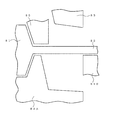
ここで、具体的に曲げ加工において発生する問題を述べる。図5は、リードフレームを曲げ加工する金型の概略図である。そして、図示するように、半導体装置81のリードフレーム82をパンチ83で切断・曲げ加工する際に問題が発生する。
【0049】
先ず、メッキが施されたリードフレーム82を台座84A、B上に設置し、半導体装置81の封止体およびリードフレーム82を台座84Aおよびリード支持手段85で固定する。このとき、リードフレーム82の先端を台座84B上に設置するそして、パンチ83にてリードフレーム82が切断され、その他の部分は曲げ加工される。この時、パンチ83の底面とリードフレーム82の表面は接触し、粗大化した析出粒子がパンチ83の底面にくずとして付着したり、リードフレーム82に付着してしまう現象が発生する。
【0050】
しかも、現在使われているリードフレームにおいては200ピン程度を有し、狭いものでは0.4mmと狭ピッチ化している。また、半導体装置自体も大幅に小さくなっているため、前記付着物により品質不良を招くことが推測される。このことより、前述したような主金属材料がSn単体等かなるメッキ液によりメッキされることが半導体の製造工程において望ましい。
【0051】
一方、主金属がSn単体からなるメッキ膜において、以下の述べる製造方法では微量のBiが混入することがわかった。
【0052】
第1の実施の形態で説明したように、本発明のメッキ装置では、メッキ液を自由に選択することが可能であり、導電部材21の表面にSn単体の第1メッキ膜22を形成することが可能である。しかし、第2の実施の形態で述べたように、導電部材21にメッキする際にメッキ補助ラック72を使用するため、メッキ補助ラック72の表面にもメッキ膜が形成される。そして、メッキ補助ラック72はその後の工程で洗浄等が施されメッキ補助ラック72自身のメッキ膜は落とされるが、1つの搬送ラインでメッキ補助ラック72を繰り返し利用する。そのため、どうしてもSn単体の金属材料からなるメッキ液内にも、極微量のBiが混入してしまう。また、電極73として用いるアノードにも極微量のBiが不純物として混入している。よって、Sn単体のメッキ液内にもSnに対してBiがある程度混入してしまう。実際には、第1メッキ膜22がSn単体からなるメッキ膜といえども、皮膜内には極微量のBiが存在する半導体装置として形成される可能性がある。
【0053】
そのため、第1メッキ膜22にどの程度のBiが混入すると問題が発生するか調査した。Snに対してBiが0〜0.5重量%含まれている場合には析出粒子は発生しない。また、Snに対してBiが0.5〜1.0重量%含まれている場合には析出粒子の粗大化はほとんど発生しないが、問題ないレベルで微量に発生する場合もある。しかし、Biが1.0〜3.0重量%含まれている場合には、問題となるレベルの析出粒子の粗大化が発生する。そして、第1メッキ膜表面に析出粒子の粗大化が発生した場合には、当然ながら第2メッキ膜23表面も析出粒子の粗大化が発生する。
【0054】
このことから、第1のメッキ膜22がSn単体もしくは1重量%以下(特に0〜0.5重量%)のメッキ膜が形成され、その上にいかなる濃度のSn−Biメッキ膜23が形成されても粒子の粗大化は発生しないことがわかった。
【0055】
以下にリードフレームを使用する半導体装置は、リードフレームに半導体チップを搭載し、金属細線による配線を行う。その後、封止され封止部から露出したリードが曲げ加工される。そして、この単体となった半導体装置は、リードを介して電気的な測定がなされユーザへ供給される。そして、ユーザ側では、実装基板上の電極にろう材を介して固着される。
【0056】
ここにおいてメッキ処理は、半導体チップ搭載前と封止後にその処理が可能である。半導体チップ搭載前にメッキ処理する場合は、金属細線の接続部にはメッキ皮膜が施されないような処理が必要である。一方、封止後に処理する場合は、封止部より露出している金属導電部をメッキ薬品に浸漬可能であり、選択的な被着が不要であるメリットがある。なお、回路装置として半導体チップで説明したが、受動素子やこれらの複合物が封止されてもよい。また、封止材料としては、熱可塑性,熱硬化性樹脂やセラミックなどが対象として処理できる。
【0057】
また、支持基板上の電極にマトリックス状に半導体チップを固着し、その後封止した後に個別化するようなCSPなどの電極にも適用できる。この場合には全ての電極に通電可能な手段が必要である。
【0058】
【発明の効果】
以上の説明で明らかなように、本発明のメッキ装置には次のような効果が得られる。
【0059】
第1の効果としては、このメッキ装置は半田メッキラインにてメッキ液を両浴槽間を移動させる機能を有することにより、1本の搬送レールで連続して単層のまたは複数の組み合わせのメッキ膜を形成することができる。そのため、導電部材に形成するメッキ膜が換わるごとにメッキ液を交換することがなくなり、メッキ装置を一時停止することがない。このことにより、1本の搬送レールで連続して導電部材に複数の組み合わせのメッキ膜を形成することができるため作業時間を大幅に短縮させることができ、かつ、メッキ液を入れ換える手間を省くことができる。また、同一の浴槽でのメッキ液の入れ換えのとき、それぞれのメッキ液どうしが混入することがなくなりメッキ液の管理およびメッキ浴槽、メッキ用設備などのメンテナンスにおける労力も大幅に減らすことができる。
【0060】
第2の効果としては、本発明のメッキ方法でメッキ作業を行うことにより、表面積等の異なる様々な導電部材に対して強い電流密度の大部分を導電部材から逃がしてメッキすることができる。そのことにより、表面積やデザイン等の異なる導電部材に対して、使用するメッキ液の好適な範囲内の電流密度で、なお、メッキ液内の電界がコントロールされ、導電部材の全ての表面により均一に電流密度がかかるようになる。その結果、様々な導電部材に対してメッキ膜厚およびメッキ膜組成分布の最適化と均一性のとれたメッキ膜を形成できるようになる。
【0061】
第3の効果としては、このメッキ方法に用いるメッキ装置では、つまり、導電材質の部材で構成された4本の主柱から成る直方体の形をしたメッキ補助ラックを使用することで表面積等の異なる様々な導電部材に対しても高品質なメッキ膜を形成することができる。
【0062】
第4の効果としては、Cu単体、Cu合金またはFe―Ni合金のような導電部材の表面に複数層のメッキ膜が施される半導体装置の製造方法において、第1メッキ膜がSn−Biの金属材料、特に、微量のBiが混入するSnを主金属材料とするメッキ液を用いてメッキ膜が形成されるが、第1メッキ膜の表面には析出粒子が発生しない、または、発生しても極微細な析出粒子である良好なメッキ膜を有する半導体装置の製造方法を実現することができる。
【図面の簡単な説明】
【図1】本発明のメッキ装置に用いるメッキラインを説明する図である。
【図2】本発明のメッキ装置に用いるメッキラインを説明する図である。
【図3】本発明のメッキ装置に用いるメッキ補助ラックを説明する図である。
【図4】本発明のメッキ装置に用いるメッキ浴槽でメッキ作業を行う図を上から見たレイアウトである。
【図5】本発明の半導体装置の製造方法を説明する図である。
【図6】本発明および従来のメッキを施す半導体チップを説明する図である。
【図7】本発明および従来の2層メッキ膜からなる図3に示した半導体リードフレームのA−A方向からみた断面を説明する図である。
【図8】本発明および従来の自動メッキ装置全体のレイアウトを説明する図である。
【図9】本発明および従来の図5に示した自動メッキ装置全体の化学エッチング浴槽のB−B方向からみた断面を説明する図である。[0001]
BACKGROUND OF THE INVENTION
The present invention relates to a lead and lead frame mainly made of Cu or Fe—Ni alloy, and a plating film layer such as an electrode of a chip size package (CSP), and a semiconductor device for forming at least two plating film layers and its manufacture Regarding the method.
[0002]
[Prior art]
A lead material obtained by coating the surface of a conductive member such as a simple substance of Cu, a Cu alloy or a Fe—Ni alloy with a plating layer of a simple substance of Sn or a Sn alloy has excellent conductivity and mechanical properties that the simple substance of Cu or the Cu alloy has. Has strength. In addition, the lead material is a high-performance conductor having both corrosion resistance and good solderability provided by Sn alone or an Sn alloy. Therefore, they are widely used in the field of electric / electronic devices such as various terminals, connectors and leads, and in the field of power cables.
[0003]
In addition, when mounting a semiconductor chip on a circuit board, solderability of the outer lead portion is improved by performing hot plating or electroplating using an Sn alloy on the outer lead portion of the semiconductor chip. ing. A typical example of such an Sn alloy is solder (Sn—Pb alloy), which has good solderability and corrosion resistance, and is widely used as an industrial plating for electrical and electronic parts such as connectors and lead frames. ing.
[0004]
FIG. 7 is a cross-sectional view showing a basic configuration of the lead material of the AA cross section in the semiconductor lead frame shown in FIG. For example, the conductive member 21 is made of Cu, a Cu-based alloy containing Cu as a main component, or a Fe—Ni-based alloy containing Fe—Ni as a main component. And the two-layer plating film of a different metal material is given to the surface of those conductive members 21. For example, the first plating film 22 of Sn and the second plating film 23 of Sn—Bi are formed in this order. Here, the thickness of the first plating film 22 is t 1 , The thickness of the
[0005]
FIG. 8 is a layout of the entire automatic plating apparatus. First, in the alkaline
[0006]
Next, after washing in the
[0007]
FIG. 9 is a cross-sectional view in the BB direction of the chemical etching bath 33 in the entire plating apparatus shown in FIG.
[0008]
The function of this chemical etching bath 33 is as described above. Here, the mechanism in this plating apparatus will be described. In this plating apparatus, the lateral
[0009]
This plating apparatus described above has one plating pretreatment line and one solder plating line. For example, when the Sn plating film is formed on the first plating film 22 and the Sn—Bi plating film is formed on the second plating film 23 on the conductive member 21, the Sn plating film is formed on the first plating film 22 on the conductive member 21. In some cases, a Sn—Ag plating film is formed on the plating film 23. In this case, the first plating film can use the same Sn plating solution, but the second plating film uses a different plating solution. Therefore, after the former plating film is formed on the conductive member 21, the plating apparatus is stopped once and the plating liquid in the bath is replaced with the latter plating liquid, and then the plating film is applied to the next conductive member 21. Was forming.
[0010]
Furthermore, in this solder plating method and the plating apparatus used therefor, the plating bath in the plating line has a plating solution for forming a plating film on the conductive member 21 and an electrode for supplying a current. Here, the electrode installed in the plating bath uses an anode mainly in electroplating. Then, the conductive member 21 is immersed in this plating bath, and at this time, the conductive member 21 forms a cathode, thereby forming a plating film. At this time, the conductive member 21 was installed in a rectangular auxiliary plating rack 334 composed of two main pillars to perform the plating operation. For example, there are conductive members 21 having different package sizes, conductive members 21 having different package designs, and conductive members 21 having different materials. When a thick plating film is formed on these conductive members 21, the plating operation is performed by applying a strong current density to the plating solution. As described above, plating films having various thicknesses are formed mainly by changing the current density.
[0011]
In electroplating, it is known that a current density is applied to the end portion of the conductive member 21, and the plating film is formed thicker. The upper limit of the current density range suitable for the plating solution is called the maximum current density. By utilizing this maximum current density, high-speed plating and plating time can be shortened. However, if this maximum current density is exceeded, the plated surface can become cloudy, and further, burns and dust can be deposited. It is also known that when the limit current density is reached, the plating film is not formed.
[0012]
[Problems to be solved by the invention]
As a first problem, as described above, this solder plating apparatus has one plating pretreatment line and one solder plating line. Therefore, when a plurality of combinations of plating films are formed on the conductive member 21, there is a problem that when the combination of the plating films is changed, it is not possible to perform operations continuously. In other words, in this plating apparatus, the conductive member 21 was sequentially immersed in the prepared plating solution, and a plating film of the same plating film combination could be continuously formed. However, depending on the intended use of the conductive member 21 to be plated, it was not possible to continuously form a plurality of combinations of plating films on the conductive member 21. In other words, the solder plating line has a problem that extra time and labor are spent replacing the plating solution.
[0013]
Furthermore, in addition to the above, a great deal of labor has been spent on managing the solder plating line. For example, after using a plating solution that is one plating bath, another plating solution having a different plating solution configuration may be used. At this time, if the former plating solution is not surely removed, the liquid configuration of the latter plating solution is changed. Also, if the plating solution composition used is different, the anode used in the plating bath must also be changed and replaced. That is, there has been a problem that a great deal of labor is spent on maintenance such as plating solution management or plating bath management.
[0014]
As a second problem, as described above, in this solder plating method and the plating apparatus used therefor, the plating bath in the plating line has a plating solution for forming a plating film on the conductive member 21 and an electrode for supplying current. is doing. And the plating film was formed using this plating apparatus. However, there are various conductive members 21 depending on the surface area and the design. Therefore, the current flows from the anode to the cathode, but the uniform current does not always pass through any part of the surface of the conductive member 21 that becomes the cathode. In other words, the portions of the conductive member 21 are not equidistant from the anode. In this plating apparatus, the conductive member 21 is installed in a rectangular auxiliary plating rack 334 having two main pillars to perform the plating operation. Therefore, since the conductive member 21 has received the current density from the anode as one surface, the current density is concentrated toward the end of the conductive member 21 and the plating film is formed thicker. The central portion of the conductive member 21 is compared to the end. A thin plating film was formed. Further, when the plating film is formed on the conductive member 21, there is a problem that the portion where the current density is strong is plated and the plating film thickness and the plating film composition distribution are not optimized and uniform.
[0015]
[Means for Solving the Problems]
The present invention has been made in view of the above-described conventional problems, and a method for manufacturing a semiconductor device according to the present invention includes a support substrate and a plurality of semiconductors electrically connected to electrodes formed on the support substrate. In a chip-size package type semiconductor device in which a chip, a sealing body in which the semiconductor chip is resin-molded, and the sealing body are individualized, Sn is a main metal material for the electrode, A first plating film layer containing about 0 to 1% by weight of Bi and a plating film layer containing Sn-Bi as a main metal material are formed on the outermost surface layer of the electrode.
[0016]
In the method for manufacturing a semiconductor device according to the present invention, after a plurality of semiconductor chips are fixed onto the electrodes formed on the support substrate, the plurality of semiconductor chips on the substrate are resin-molded to form a sealing body. In the method of manufacturing a semiconductor device in which the sealing body is divided to form a chip-size package type element, Sn is a main metal material for the electrode, and Bi is about 0 to 1 wt% with respect to Sn. After the formation of the first plating film layer containing, a plating film layer containing Sn-Bi as a main metal material is formed on the outermost surface layer of the electrode.
[0017]
Furthermore, in the method of manufacturing a semiconductor device of the present invention, preferably, after preparing a lead frame mainly composed of Cu or Fe—Ni, fixing the lead frame to a lead frame holding means, the lead frame and the The lead frame holding means is integrated to circulate the plating line to form a first plating film layer containing Sn as a main metal material on the lead frame, and plating using Sn-Bi as the main metal material on the lead outermost surface. In the method of manufacturing a semiconductor device for forming a film layer, Bi contained in the first plating film layer is brought in by the lead frame holding means, and the Bi content is about 0 to 1% by weight with respect to Sn. It is controlled to become.
[0018]
DETAILED DESCRIPTION OF THE INVENTION
First, as a first embodiment, referring to FIGS. 1, 2 and 7, in a plating apparatus having a plating pretreatment line and a plating line, a plurality of patterns of plating film layers are formed on the plating line. A plating apparatus having a plating bath for providing a plating solution storage bath in each of the plating baths is described.
[0019]
FIG. 1 is a layout schematically showing the function of a solder plating line for implementing a plating apparatus according to the present invention. In this solder plating line, a pre-dip bath 43, a first plating bath 44, a second plating bath 45, a third plating bath 46, and a washing bath 47 are installed under the
[0020]
In this invention, as a 1st form, it is a form which installs a plating solution storage bathtub only as needed corresponding to a plating bathtub. For example, as shown in FIG. 1, the first plating bath 44 is not provided with a plating solution storage bath, and the first plating solution storage bath 49 for the second plating bath 45 is replaced with the first plating bath storage bath 49 for the third plating bath 46. Two plating solution storage bathtubs 50 are respectively installed. In this case, in order to efficiently use the work space, the plating solution storage tub is installed under the plating bath so that the plating solution can be stored in a short time when the plating solution is stored. Accordingly, this solder plating line is characterized in that a plurality of combinations of plating films can be continuously formed on the conductive member 21 by one transport rail according to the intended use.
[0021]
FIG. 2 is a layout simply showing the function of the solder plating line for carrying out the plating apparatus according to the present invention, as in FIG. In this solder plating line, a pre-dip bath 53, a first plating bath 54, a second plating bath 55, a third plating bath 56, and a washing bath 57 are installed below the transfer line 52. And it sends one pitch at a time by the transverse feed type pusher 51, and forms a plating film on the conductive member 21 using those bathtubs.
[0022]
And as a 2nd form, it is a form which installs a plating solution storage bathtub with respect to all the plating bathtubs. For example, as shown in FIG. 2, the first plating solution storage bath 59 for the first plating bath 54, the second plating solution storage bath 60 for the second plating bath 55, and the third plating bath 56 for the third plating bath 56. Three plating solution storage bathtubs 61 are respectively installed. Also in this case, a plating solution storage tub was installed under the plating tub as in the first embodiment. As a result, this solder plating line is characterized in that a plurality of combinations of plating films can be continuously formed on the conductive member 21 that can be plated with one transport rail according to the intended use.
[0023]
Specifically, the first mode is the same as that of FIG. 9 described above. For example, in the solder plating line of FIG. 1, Sn plating solution is put in the first plating bath 44, Sn—Bi plating solution is put in the second plating bath 45, and the third plating bath 46 is put in the third plating bath 46. Sn—Ag plating solution is contained. And as for these plating baths, a required plating bath is selected according to the use application of the electroconductive member 21 plated, and the plating solution of the unnecessary plating bath moves to a plating solution storage bathtub. However, in this embodiment, the plating solution is always put in the first plating bath 44 containing the Sn plating solution, and the conductive member 21 is immersed in the Sn plating solution. As a result, an Sn single-layer plating film is formed on the conductive member 21, or a Sn-Bi or Sn-Ag plating film is formed on the first layer and the second layer. Since the lead material has the same structure as that shown in FIG.
[0024]
First, a case where only the first Sn plating layer 22 is formed on the conductive member 21 will be described. Here, the Sn plating solution is always contained in the first plating bath 44 containing the Sn plating solution, and the Sn plating film is formed on the conductive member 21. First, the conductive member 21 treated in the above-described plating pretreatment line removes the surface hydroxide film in the pre-dip bath 43 and is immersed in the Sn plating solution in the first plating bath 44. In the meantime, in the second plating bath 45 and the third plating bath 46, no plating film is formed on the conductive member 21, so that the plating solution in the bath goes to the first plating solution storage bath 49 and the second plating solution storage bath 50. And move. The conductive member 21 in which the Sn plating film is formed in the first plating bath 44 is conveyed to the second plating bath 45 and the third plating bath 46, but plating is not performed in these plating baths because the plating solution is not contained therein. No film is formed. Next, the surface of the conductive member 21 on which the plating film is formed is washed in the washing bath 47. As a result, an Sn single-layer plating film is formed on the conductive member 21.
[0025]
Secondly, a case where the two-layered first plating film 22 and second plating film 23 are formed on the conductive member 21 will be described. The process of forming a plating film on the conductive member 21 is the same as described above. First, since the Sn plating solution is always contained in the first plating bath 44, the Sn first plating film 22 is formed on the conductive member 21. Then, a plating bath for forming the second plating film 23 is selected according to the intended use of the conductive member 21. Here, when the Sn—Bi second plating film 23 is formed first, the Sn—Ag plating solution in the third plating bath 46 is moved to the second plating solution storage bath 50. Then, when the second plating film of Sn—Ag is formed next, the Sn—Bi plating solution in the second plating bath 45 is moved to the first plating solution storage bath 49, and the second plating bath 46 is moved to the second plating bath 46. The Sn—Ag plating solution is returned from the plating solution storage bath 50. As a result, a two-layer plating film of Sn and Sn—Bi or Sn and Sn—Ag is formed on the conductive member 21.
[0026]
In the plating apparatus of FIG. 1, the metal material of the plating solution in the first plating bath 44 is Sn, the metal material of the plating solution in the second plating bath 45 is Sn-Bi, and the The metal material of the plating solution is Sn-Ag. And since the solution except those metals and the solvent which dissolves it has the same liquid composition, a plating film can be formed continuously on the conductive member 21. However, a plating film may be formed on the conductive member 21 with plating liquids having different liquid configurations. At this time, by preparing a plating bath in which pure water is put between plating baths having different plating solution configurations, and cleaning the surface of the plated conductive member 21, the plating solutions having different liquid configurations are mixed. To prevent. And when this pure water is not required, it puts into the plating solution storage bathtub. Thus, a plurality of combinations of plating films can be continuously formed on the conductive member 21 by one transport rail regardless of the liquid composition of the plating liquid.
[0027]
When it says concretely about a 2nd form, about the plating method of this solder plating line, it is the same as that of the above-mentioned 1st form. For example, in the solder plating line of FIG. 2, the first plating bath 54 is filled with Sn plating solution, and the second plating bath 55 is plated with Sn: Bi = 98 (wt%): 2 (wt%). The third plating bath 56 is filled with Sn: Bi = 43 (wt%): 57 (wt%) plating liquid. And as for these plating baths, a required plating bath is selected according to the use application of the electroconductive member 21 plated, and the plating solution of the unnecessary plating bath moves to a plating solution storage bathtub. As a result, a single-layer plating film of Sn or Sn: Bi = 98 (wt%): 2 (wt%) is formed on the conductive member 21, or the first layer is Sn and the second layer is Sn: Bi = 43 ( (% By weight): 57 (% by weight) of a two-layer plating film is formed, or Sn: Bi = 98 (% by weight) for the first layer: 2 (% by weight) and Sn: Bi = 43 (for the second layer). (2% by weight): 57 (% by weight) of a two-layer plating film or the like may be formed.
[0028]
In the second embodiment, a plating solution of Sn: Bi = 98 (wt%): 2 (wt%) can be used to form the first plating film 22 on the conductive member 21. At this time, whisker (needle crystal) is remarkably suppressed in the first plating film 22 by including about several percent Bi in the plating solution.
[0029]
Therefore, in the present invention, a plating bath in which a plurality of plating solutions having different plating solution configurations are put, and a plating solution storage bath is installed in the plating bath as necessary or in all. And according to the use application of the electrically-conductive member 21, a plating solution can move those both bathtubs. As a result, a plurality of combinations of plating films can be formed continuously with a single transport rail.
[0030]
That is, a plurality of combinations of plating films can be continuously formed on the conductive member 21 with one transport rail. This eliminates the need to temporarily stop the plating apparatus according to the combination of plating films and replace the plating solution in the bathtub. As a result, the working time can be greatly shortened and the trouble of replacing the plating solution can be saved. Further, when the plating solutions are replaced in the same bath, the respective plating solutions are not mixed, and the labor in the management of the plating solution and the maintenance of the plating bath and plating equipment can be greatly reduced.
[0031]
In addition, a plurality of combinations of plating films can be continuously formed with one transport rail. For example, in the first plating bath, the plating solution is moved to the first plating solution storage bath, and a plating film is formed in the second and third plating baths. In the first and second plating baths, the first and second plating solutions are used. There is a method in which a single plating film is formed only by a third plating bath by moving to a 2 plating solution storage bath. Further, a thick plating film can be formed on the conductive member 21 by putting plating solutions having the same composition into adjacent plating baths.
[0032]
In any case, as described above, by moving the plating solution according to the present invention between both baths, it is possible to continuously form a plurality of combinations of plating films on one transport rail. is there.
[0033]
As described above, the case of solder plating has been described as an example, but this plating apparatus can be used without being limited to solder plating. For example, there are Sn plating, Cu plating, and Ni plating. Also in these cases, a plurality of combinations of plating films can be formed on the conductive member 21 continuously with one transport rail using this plating apparatus.
[0034]
Next, as a second embodiment, a plating auxiliary rack having a rectangular parallelepiped structure around four main pillars and a plating method using this plating auxiliary rack will be described with reference to FIGS. 3, 4 and 7. Describe.
[0035]
FIG. 3 is a layout simply showing an auxiliary plating rack for carrying out the plating method according to the present invention. 4 is a layout of the conductive member 21 (see FIG. 7) installed in the auxiliary plating rack 72 shown in FIG. Here, electroplating will be described assuming that the electrode 73 is the anode 73 in order to mainly use the conductive member 21 as a cathode.
[0036]
In the present invention, when a plating film is formed on the conductive member 21, by using a plating auxiliary rack 72 having a rectangular parallelepiped shape composed of four main pillars, the conductive member 21 can be applied to any part of various conductive members 21 having different surface areas. It is characterized in that the current density is applied uniformly.
[0037]
Specifically, the plating solution has a current density range suitable for each plating solution when performing the plating operation, and a high-quality plating film can be formed by performing the plating operation within the range. . In this plating method, the conductive member 21 is placed on a rectangular parallelepiped plating auxiliary rack 72 composed of four main pillars, and the plating auxiliary rack 72 is immersed in the plating solution in the plating bath 71. Since the auxiliary plating rack 72 is formed of a conductive material member, the negative electrode is formed integrally with the conductive member 21. As shown in FIG. 2, since the conductive member 21 is installed so as to be positioned at the center of the auxiliary plating rack 72, the main pillar of the auxiliary plating rack 72 is positioned between the anode 73 and the conductive member 21. It will be. As a result, most of the portion having a high current density is directed to the main pillar of the auxiliary plating rack 72, and the other current density is applied to the conductive member 21 to form a plating film. As a result, a plating film having a uniform plating film composition distribution can be formed with a uniform plating film thickness on various conductive members 21 such as a conductive member 21 having a large surface area and a conductive member having a small surface area.
[0038]
For example, a plating film may be formed on the conductive member 21 having a large surface area. Here, the plating solution has a current density in a range suitable for the plating solution. And since the surface area is large, there is a difference in how the current density is applied between the central portion and the end portion of the conductive member 21. In this case, as described above, the main column of the auxiliary plating rack 72 is interposed between the conductive member 21 and the anode 73, so that the electrolytic adjustment in the plating solution is assisted so as to avoid most of the high current density portion. To do. As a result, the difference in current density between the central portion of the conductive member 21 close to the anode 73 and the end of the conductive member 21 far from the anode 73 becomes small, and the surface of the conductive member 21 is uniformly plated with a uniform film thickness. A plating film having a film composition is formed.
[0039]
In some cases, a Pb-free plating layer is formed with Sn as the first layer and Sn—Bi as the second layer. At this time, the Sn—Bi plating film of the second layer is plated in the range of about 1 to 5 μm. Here, when plating is performed without using the auxiliary plating rack 72, due to the electroplating characteristics, as described above, in the thin Sn-Bi plating film, the plating film thickness varies particularly at the end portion and the central portion of the conductive member 21. Or parts that are not formed. However, by using the plating auxiliary rack 72, a plating film having a uniform plating film composition is formed on the surface of the conductive member 21 with a uniform film thickness without forming an unformed portion.
[0040]
Here, the plating apparatus used for the plating method which is this invention is demonstrated. In this plating apparatus, a plating auxiliary rack 72 made of a conductive material member is used. The auxiliary plating rack 72 has a rectangular parallelepiped shape composed of four main pillars. The auxiliary plating rack 72 is installed between the conductive member 21 and the anode 73 with the conductive member 21 in the center, and assists in forming a plating film. At that time, the auxiliary plating rack 72 forms a cathode integrally with the conductive member 21 and assists in adjusting the electric field in the plating solution so that a plating film having a uniform plating film composition is formed with a uniform film thickness.
[0041]
Therefore, in this plating method and the plating apparatus used therefor, when the plating film is formed on the conductive member 21, the auxiliary plating rack 72 in the shape of a rectangular parallelepiped composed of four main pillars made of a conductive material member is provided. use. Thus, the auxiliary plating rack 72 forms a cathode integrally with the conductive member 21, and the four main pillars of the auxiliary plating rack 72 are positioned between the conductive member 21 and the anode 73, so that the current density is increased. It is possible to avoid the formation of a plating film by directly applying the strong portion to the conductive member 21. As a result, the electrolysis in the plating solution is adjusted with the assistance of the plating auxiliary rack 72, and a uniform current density is applied to all surfaces of the conductive member 21.
[0042]
That is, by forming a plating film on the conductive member 21 using the plating auxiliary rack 72, it becomes possible to form a plating film with optimized and uniform plating film thickness and plating film composition distribution.
[0043]
As described above, the case of solder plating has been described as an example, but this plating apparatus can be used without being limited to solder plating. For example, there are Sn plating, Cu plating, and Ni plating. Also in these cases, a plating film can be formed on various types of conductive members 21 under conditions suitable for the plating solution by the plating apparatus used in this plating method.
[0044]
Further, as described above, the embodiment in which the electrode 73 is the anode 73 has been described. However, even when the electrode 73 is the cathode 73, the plating film can be formed on the conductive member 21 by the same plating method.
[0045]
Finally, as a third embodiment, a lead plating method used in a semiconductor device will be described with reference to FIGS.
[0046]
First, in the first plating film 22 plated on the surface of the conductive member 21 such as a simple substance of Cu, a Cu alloy or a Fe—Ni alloy, when a plating solution whose main metal material is a simple substance of Sn is plated, A smooth film is formed on the surface 22 of the first plating film. However, when two kinds of metals such as Sn-Bi are plated as the first plating film 22, the first plating film has a feature that Bi having a large ionization tendency is preferentially deposited. Due to this phenomenon, the surface of the first plating film 22 is formed with non-smooth precipitated particles.
[0047]
As a result, when an operation of contacting the lead frame is added, problems described later occur. For example, in the bending process, the preferentially deposited non-smooth particles fall off in the step of judging the quality of the IC by contacting the current-carrying terminals with the lead frame, and the dropped particles adhere between the leads. This is a case where a defect is caused. In addition, when the lead frame is transported, it turns around after the frictional resistance of the surface decreases and stays on the transport means contacting the lead frame.
[0048]
Here, the problem which generate | occur | produces in a bending process is described concretely. FIG. 5 is a schematic view of a mold for bending a lead frame. As shown in the figure, a problem occurs when the lead frame 82 of the semiconductor device 81 is cut and bent by the punch 83.
[0049]
First, the plated lead frame 82 is placed on the bases 84A and B, and the sealing body of the semiconductor device 81 and the lead frame 82 are fixed by the base 84A and the lead support means 85. At this time, the tip of the lead frame 82 is placed on the base 84B, and the lead frame 82 is cut by the punch 83, and the other portions are bent. At this time, the bottom surface of the punch 83 and the surface of the lead frame 82 come into contact with each other, and a phenomenon occurs in which coarse precipitate particles adhere to the bottom surface of the punch 83 as waste or adhere to the lead frame 82.
[0050]
Moreover, currently used lead frames have about 200 pins, and narrow ones have a narrow pitch of 0.4 mm. Moreover, since the semiconductor device itself is also greatly reduced, it is estimated that the deposits cause quality defects. Therefore, it is desirable in the semiconductor manufacturing process that the main metal material as described above is plated with a plating solution made of Sn alone or the like.
[0051]
On the other hand, it was found that a trace amount of Bi is mixed in the manufacturing method described below in a plating film in which the main metal is composed of Sn alone.
[0052]
As described in the first embodiment, in the plating apparatus of the present invention, the plating solution can be freely selected, and the first plating film 22 made of Sn alone is formed on the surface of the conductive member 21. Is possible. However, as described in the second embodiment, since the auxiliary plating rack 72 is used when the conductive member 21 is plated, a plating film is also formed on the surface of the auxiliary plating rack 72. Then, the plating auxiliary rack 72 is cleaned in a subsequent process and the plating film of the plating auxiliary rack 72 itself is dropped, but the plating auxiliary rack 72 is repeatedly used in one transport line. Therefore, a very small amount of Bi is inevitably mixed in the plating solution made of a metal material of Sn alone. An extremely small amount of Bi is also mixed as an impurity in the anode used as the electrode 73. Therefore, Bi is mixed to some extent in Sn plating solution. Actually, even though the first plating film 22 is a plating film made of Sn alone, there is a possibility that the first plating film 22 is formed as a semiconductor device in which a very small amount of Bi exists in the film.
[0053]
Therefore, it was investigated how much Bi would enter the first plating film 22 to cause a problem. When Bi is contained in an amount of 0 to 0.5% by weight with respect to Sn, no precipitated particles are generated. Further, when Bi is contained in an amount of 0.5 to 1.0% by weight with respect to Sn, the coarsening of the precipitated particles hardly occurs, but it may occur in a minute amount at a problem-free level. However, when Bi is contained in an amount of 1.0 to 3.0% by weight, the coarsening of precipitated particles at a problematic level occurs. When the coarsening of the precipitated particles occurs on the surface of the first plating film, naturally the coarsening of the precipitated particles also occurs on the surface of the second plating film 23.
[0054]
Therefore, the first plating film 22 is formed of Sn alone or 1 wt% or less (especially 0 to 0.5 wt%) of plating film, and the Sn—Bi plating film 23 of any concentration is formed thereon. However, it was found that no coarsening of the particles occurred.
[0055]
In the following, a semiconductor device using a lead frame has a semiconductor chip mounted on the lead frame and performs wiring with fine metal wires. Thereafter, the lead that is sealed and exposed from the sealing portion is bent. The single semiconductor device is electrically measured via a lead and supplied to the user. On the user side, it is fixed to the electrode on the mounting substrate via a brazing material.
[0056]
Here, the plating process can be performed before mounting the semiconductor chip and after sealing. When the plating process is performed before mounting the semiconductor chip, it is necessary to perform a process so that the plating film is not applied to the connection portion of the fine metal wire. On the other hand, when processing after sealing, the metal conductive part exposed from the sealing part can be immersed in the plating chemical, and there is an advantage that selective deposition is unnecessary. Although the semiconductor device has been described as the circuit device, a passive element or a composite thereof may be sealed. Moreover, as a sealing material, thermoplasticity, a thermosetting resin, a ceramic, etc. can be processed.
[0057]
Further, the present invention can also be applied to an electrode such as a CSP in which a semiconductor chip is fixed to an electrode on a support substrate in a matrix and then sealed and then individualized. In this case, a means capable of energizing all the electrodes is necessary.
[0058]
【The invention's effect】
As apparent from the above description, the plating apparatus of the present invention has the following effects.
[0059]
As a first effect, this plating apparatus has a function of moving a plating solution between both bathtubs in a solder plating line, so that a single layer or a plurality of combinations of plating films are continuously provided on one transport rail. Can be formed. Therefore, the plating solution is not changed every time the plating film formed on the conductive member is changed, and the plating apparatus is not temporarily stopped. As a result, a plurality of combinations of plating films can be continuously formed on the conductive member with one transport rail, so that the working time can be greatly shortened and the trouble of replacing the plating solution can be saved. Can do. Further, when the plating solutions are exchanged in the same bath, the plating solutions are not mixed with each other, and the labor in the management of the plating solutions and the maintenance of the plating bath and plating facilities can be greatly reduced.
[0060]
As a second effect, by performing the plating operation by the plating method of the present invention, it is possible to plate most of the strong current density from various conductive members having different surface areas and the like from the conductive member. As a result, with respect to conductive members with different surface areas and designs, etc., the electric field in the plating solution is controlled at a current density within a suitable range of the plating solution to be used, and it is more uniform on all surfaces of the conductive member. Current density is applied. As a result, it is possible to form a plating film with optimized and uniform plating film thickness and plating film composition distribution for various conductive members.
[0061]
As a third effect, in the plating apparatus used in this plating method, that is, by using a plating auxiliary rack in the shape of a rectangular parallelepiped composed of four main pillars made of conductive material members, the surface area and the like are different. High quality plated films can be formed on various conductive members.
[0062]
As a fourth effect, in the method of manufacturing a semiconductor device in which a plurality of layers of plating films are applied to the surface of a conductive member such as Cu alone, Cu alloy, or Fe—Ni alloy, the first plating film is made of Sn—Bi. A plating film is formed by using a plating solution containing a metal material, particularly Sn mixed with a small amount of Bi as a main metal material, but no precipitated particles are generated or generated on the surface of the first plating film. In addition, it is possible to realize a method for manufacturing a semiconductor device having a good plated film that is very fine precipitated particles.
[Brief description of the drawings]
FIG. 1 is a diagram illustrating a plating line used in a plating apparatus of the present invention.
FIG. 2 is a diagram for explaining a plating line used in the plating apparatus of the present invention.
FIG. 3 is a diagram illustrating a plating auxiliary rack used in the plating apparatus of the present invention.
FIG. 4 is a layout of a top view of a diagram in which a plating operation is performed in a plating bath used in the plating apparatus of the present invention.
FIG. 5 is a diagram illustrating a method for manufacturing a semiconductor device of the present invention.
FIG. 6 is a diagram for explaining a semiconductor chip to which the present invention and a conventional plating are applied.
7 is a view for explaining a cross section of the semiconductor lead frame shown in FIG. 3 made of the present invention and a conventional two-layer plating film as seen from the AA direction. FIG.
FIG. 8 is a diagram for explaining a layout of the entire automatic plating apparatus of the present invention and a conventional one.
FIG. 9 is a view for explaining a cross section of the chemical etching bath of the entire automatic plating apparatus shown in FIG.
Claims (1)
前記リードフレームをリードフレーム保持手段に固定した後、
前記リードフレームおよび前記リードフレーム保持手段を一体にメッキラインに巡回させて、前記リードフレームにSnから成るメッキ膜層を形成し、リード最表面にはSn−Biから成るメッキ膜層を形成し、
前記リードフレームを切断する半導体装置の製造方法において、
前記Snから成るメッキ膜層には、前記リードフレーム保持手段の巡回によりBiが持ち込まれても、前記Biは、前記Snに対して1重量%の含有率まで容認するように制御して、前記Snから成るメッキ膜層に生成される析出粒子を防止し、
前記リードフレームの切断の際に発生する前記析出粒子の脱落を防止することを特徴とする半導体装置の製造方法。Preparing a lead frame mainly composed of Cu or Fe-Ni,
After fixing the lead frame to the lead frame holding means,
The lead frame and the lead frame holding means are circulated integrally on a plating line to form a plated film layer made of Sn on the lead frame, and a plated film layer made of Sn-Bi is formed on the outermost surface of the lead,
In the method of manufacturing a semiconductor device for cutting the lead frame ,
Even if Bi is brought into the plating film layer made of Sn by circulation of the lead frame holding means, the Bi is controlled so as to allow a content of 1% by weight with respect to the Sn, and Prevents precipitated particles generated in the plating film layer made of Sn,
A method of manufacturing a semiconductor device, wherein the drop of the precipitated particles generated when the lead frame is cut is prevented .
Priority Applications (1)
| Application Number | Priority Date | Filing Date | Title |
|---|---|---|---|
| JP2002253781A JP3995564B2 (en) | 2000-03-29 | 2002-08-30 | Semiconductor device and manufacturing method thereof |
Applications Claiming Priority (6)
| Application Number | Priority Date | Filing Date | Title |
|---|---|---|---|
| JP2000-91048 | 2000-03-29 | ||
| JP2000091048 | 2000-03-29 | ||
| JP2000-96097 | 2000-03-31 | ||
| JP2000096097 | 2000-03-31 | ||
| PCT/JP2001/010873 WO2003050328A1 (en) | 2000-03-29 | 2001-12-12 | Plating apparatus, plating method, and method for manufacturing semiconductor device |
| JP2002253781A JP3995564B2 (en) | 2000-03-29 | 2002-08-30 | Semiconductor device and manufacturing method thereof |
Related Parent Applications (1)
| Application Number | Title | Priority Date | Filing Date |
|---|---|---|---|
| JP2001095257A Division JP3568486B2 (en) | 2000-03-29 | 2001-03-29 | Method for manufacturing semiconductor device |
Publications (2)
| Publication Number | Publication Date |
|---|---|
| JP2003160896A JP2003160896A (en) | 2003-06-06 |
| JP3995564B2 true JP3995564B2 (en) | 2007-10-24 |
Family
ID=27808708
Family Applications (1)
| Application Number | Title | Priority Date | Filing Date |
|---|---|---|---|
| JP2002253781A Expired - Fee Related JP3995564B2 (en) | 2000-03-29 | 2002-08-30 | Semiconductor device and manufacturing method thereof |
Country Status (1)
| Country | Link |
|---|---|
| JP (1) | JP3995564B2 (en) |
-
2002
- 2002-08-30 JP JP2002253781A patent/JP3995564B2/en not_active Expired - Fee Related
Also Published As
| Publication number | Publication date |
|---|---|
| JP2003160896A (en) | 2003-06-06 |
Similar Documents
| Publication | Publication Date | Title |
|---|---|---|
| CN101908515A (en) | Semiconductor device and preparation method thereof | |
| US20040235219A1 (en) | Plating apparatus, plating method, and method for manufacturing semiconductor device | |
| JP4029936B2 (en) | Manufacturing method of semiconductor device | |
| US20040026256A1 (en) | Method and apparatus for protecting tooling in a lead-free bath | |
| US7772043B2 (en) | Plating apparatus, plating method and manufacturing method for semiconductor device | |
| KR100574304B1 (en) | Plating Apparatus | |
| KR100695373B1 (en) | Plating apparatus | |
| JP3995564B2 (en) | Semiconductor device and manufacturing method thereof | |
| KR20050054826A (en) | Electroplating method for a semiconductor device | |
| JP3568486B2 (en) | Method for manufacturing semiconductor device | |
| JP4027324B2 (en) | Semiconductor device | |
| CN1318651C (en) | Plating apparatus, plasting method and method for mfg. semiconductor device | |
| KR100695372B1 (en) | Plating method | |
| KR20040058113A (en) | Plating apparatus, plating method, and method for manufacturing semiconductor device | |
| JP3548081B2 (en) | Plating method and plating apparatus used therefor | |
| KR20070005027A (en) | Method for manufacturing semiconductor device | |
| JP3557150B2 (en) | Plating equipment | |
| KR100582129B1 (en) | Plating device | |
| KR20070094253A (en) | Method of plating for lead frame of semiconductor package | |
| JP2008190005A (en) | Method of manufacturing semiconductor device | |
| JP2009084669A (en) | Method for producing semiconductor device | |
| JPH11200097A (en) | Barrel plating method for chip parts | |
| JPH07153888A (en) | Semiconductor manufacturing apparatus and manufacture of semiconductor integrated circuit device |
Legal Events
| Date | Code | Title | Description |
|---|---|---|---|
| A977 | Report on retrieval |
Free format text: JAPANESE INTERMEDIATE CODE: A971007 Effective date: 20040601 |
|
| A131 | Notification of reasons for refusal |
Free format text: JAPANESE INTERMEDIATE CODE: A131 Effective date: 20050308 |
|
| A521 | Request for written amendment filed |
Free format text: JAPANESE INTERMEDIATE CODE: A523 Effective date: 20050428 |
|
| RD01 | Notification of change of attorney |
Free format text: JAPANESE INTERMEDIATE CODE: A7421 Effective date: 20051226 |
|
| A131 | Notification of reasons for refusal |
Free format text: JAPANESE INTERMEDIATE CODE: A131 Effective date: 20060328 |
|
| A521 | Request for written amendment filed |
Free format text: JAPANESE INTERMEDIATE CODE: A523 Effective date: 20060519 |
|
| TRDD | Decision of grant or rejection written | ||
| A01 | Written decision to grant a patent or to grant a registration (utility model) |
Free format text: JAPANESE INTERMEDIATE CODE: A01 Effective date: 20070703 |
|
| A61 | First payment of annual fees (during grant procedure) |
Free format text: JAPANESE INTERMEDIATE CODE: A61 Effective date: 20070731 |
|
| FPAY | Renewal fee payment (event date is renewal date of database) |
Free format text: PAYMENT UNTIL: 20100810 Year of fee payment: 3 |
|
| FPAY | Renewal fee payment (event date is renewal date of database) |
Free format text: PAYMENT UNTIL: 20100810 Year of fee payment: 3 |
|
| FPAY | Renewal fee payment (event date is renewal date of database) |
Free format text: PAYMENT UNTIL: 20100810 Year of fee payment: 3 |
|
| FPAY | Renewal fee payment (event date is renewal date of database) |
Free format text: PAYMENT UNTIL: 20110810 Year of fee payment: 4 |
|
| FPAY | Renewal fee payment (event date is renewal date of database) |
Free format text: PAYMENT UNTIL: 20120810 Year of fee payment: 5 |
|
| FPAY | Renewal fee payment (event date is renewal date of database) |
Free format text: PAYMENT UNTIL: 20130810 Year of fee payment: 6 |
|
| R250 | Receipt of annual fees |
Free format text: JAPANESE INTERMEDIATE CODE: R250 |
|
| LAPS | Cancellation because of no payment of annual fees |