JP3990761B2 - Manufacturing method of welded pipe with excellent roundness - Google Patents
Manufacturing method of welded pipe with excellent roundness Download PDFInfo
- Publication number
- JP3990761B2 JP3990761B2 JP06276297A JP6276297A JP3990761B2 JP 3990761 B2 JP3990761 B2 JP 3990761B2 JP 06276297 A JP06276297 A JP 06276297A JP 6276297 A JP6276297 A JP 6276297A JP 3990761 B2 JP3990761 B2 JP 3990761B2
- Authority
- JP
- Japan
- Prior art keywords
- roll
- diameter
- pipe
- welded
- tube
- Prior art date
- Legal status (The legal status is an assumption and is not a legal conclusion. Google has not performed a legal analysis and makes no representation as to the accuracy of the status listed.)
- Expired - Fee Related
Links
Images
Landscapes
- Bending Of Plates, Rods, And Pipes (AREA)
Description
【0001】
【産業上の利用分野】
本発明は、管端部を含め全長にわたって真円度に優れた溶接管を製造する方法に関する。
【0002】
【従来の技術】
溶接管をロール成形法で製造する場合、所定幅にスリットされた金属帯が管素材として使用される。金属帯は、多段配置された各成形スタンドで幅方向に順次曲げ加工され、最終的には幅方向両端部を突き合せた円筒形状に成形される。次いで、幅方向両端部を突合せ溶接し、素管を得る。この素管をサイジング工程に通し、複数段の成形ロールで管の直径を絞り寸法精度及び真円度を向上させている。その後、定寸切断され、製品管となる。
ロール成形法では、成形スタンドの多段配置が必要とされる。しかも、製造しようとする管の直径が異なると、それに応じて各スタンドの成形ロールを組み替えることが要求される。成形ロールの組替えや各スタンド間の調整は、非常に面倒な作業であり、生産性を向上させる上でのネックとなる。
そこで、本発明者等は、金属帯に曲げ・曲げ戻し歪みを付与するとき金属帯が板幅方向にカールする性質を利用し、多数の成形ロールを必要としないロールレスフォーミング法を開発した(特公平6−77773号公報)。この方法では、板幅方向と平行な小径の曲げロールによって、管内面となる面を内側にして金属帯を連続的に曲げ・曲げ戻し加工し、曲げ・曲げ戻しによる板幅方向の曲がりを利用して金属帯を円筒形状に成形する。
【0003】
【発明が解決しようとする課題】
ロール成形法による造管では、ロール表面が接触する管の周方向位置に応じてロール表面の曲率が異なる。そのため、管の周方向位置に応じて、成形ロールによって受ける加工の形態や歪み量等が異なる。このような成型工程を経た溶接管には管周方向に沿ってバラツキのある応力分布が内在しており、管を切断した際に切断端面の断面形状が残留応力によって変化し、結果として管端部の真円度を低下させる。特に製造しようとする溶接管が肉厚比(肉厚/管外径)の小さい薄肉管や高強度材料からなる管である場合、真円度が低下する傾向が顕著になる。ロールレスフォーミング法で造管した場合にも、ロール成形法ほどではないが、依然として管端部における真円度の低下がみられる。
本発明は、このような問題を解消すべく案出されたものであり、溶接後の扁平加工によって残留応力を開放し、管端部でも残留応力に起因した変形を抑え、真円度の高い溶接管を製造することを目的とする。
【0004】
【課題を解決するための手段】
本発明の溶接管製造方法は、その目的を達成するため、金属帯を板幅方向に曲げ加工し、断面をほぼ真円形状に保持した状態で板幅方向両端部を突合せ溶接した後、溶接部から管底部までの距離が目標製品外径よりも小さくなるように溶接素管をオーバベンドロールで扁平加工し、次いで溶接素管を前記オーバベンドロールによる扁平率に応じて、式(1)で与えられる数値が5〜11の範囲になるように矯正ロールによる直径絞り率を調整してほぼ真円形状に矯正ロールで成形することを特徴とする。
扁平率(%)+10×直径絞り率(%)・・・・(1)
ただし、扁平率は(溶接素管直径−扁平後の高さ)/溶接素管直径×100(%)で表し、直径絞り率は(溶接素管直径−矯正後直径)/溶接素管直径×100(%)で表す。
扁平加工では、溶接部から管底部までの距離が目標製品外径よりも3〜10%小さくなるように溶接素管を扁平加工することが好ましい。
【0005】
【実施の形態】
ロール成形法による造管では、金属帯が各成形スタンドで板幅方向に順次曲げられ、円筒状に成形される。また、図1に示すロールレスフォーミング法では、アンコイラ1から巻き出された金属帯2は、小径ロール3により曲げ・曲げ戻し加工される。金属帯2は、曲げ・曲げ戻し加工で生じた板幅方向の曲がりによって、サイドロール4に至る過程で板幅方向にカールし、円筒形状に変形する。
円筒状に成形された金属帯2は、シームガイドロール5で板幅方向両端部を案内されながらスクイズロール6に送り込まれ、板幅方向両端部が溶接装置7で突合せ溶接される。溶接素管8は、オーバベンドロール9で扁平加工された後、引抜き装置10を経て矯正ロール11で真円形状に加工される。次いで、切断装置12により定寸切断され、製品溶接管となる。
【0006】
ロール成形法及びロールレスフォーミング法の何れにおいても、程度の差はあれ、金属帯1を筒状に成形する過程で発生する歪みの形態や大きさが金属帯1の板幅方向に関して異なる。また、溶接素管8の断面形状を矯正ロール11で調整する際にも、矯正ロール11から受ける歪みは、溶接素管8の円周方向に関して一様でない。このように、複雑な変形経路を経た溶接素管8には円周方向に沿って不均一な残留応力が分布しており、また残留応力の分布状態を予め把握することはできない。
残留応力は、管端部から離れた箇所では釣り合った状態にある。そのため、矯正ロール11による矯正条件を適正に選定するとき、溶接素管8の真円度を確保できる。しかし、溶接素管8が切断されると、切断端面近傍における残留応力の釣合い状態が崩れ、管端が変形した状態で再び残留応力が釣り合う。そのため、溶接素管8の真円度が良好となるように矯正条件を選定しても、溶接素管8を切断して得た製品溶接管では管端部近傍の真円度が悪化する。
【0007】
本発明においては、このような残留応力の釣り合い状態が崩れた結果である変形を防止するため、スクイズロール6でほぼ真円状に保持した状態で金属帯1を溶接した後、溶接部から管底部までの距離を目標製品外径よりも小さくなるようにオーバベンドロール9で扁平化している。オーバベンドロール9としては、ロール最小径部を含む部分に目標製品半径×1.1〜1.4程度の半径をもつカリバーを付けたロールが好ましい。このようなオーバベンドロール9により、目標製品外径を基準として3〜10%の扁平量で溶接素管8が扁平加工される。
カリバー形状については、目標製品半径に等しい半径のカリバーでは全く扁平化することが困難であるため、目標製品半径よりも大きな半径をもつカリバーにすることが必要である。具体的には、目標製品半径の1〜1.4倍程度の半径をもつカリバーで所望の扁平変形を実施することが可能である。
扁平化に引き続いて実施される矯正ロールによる直径絞り加工と併用して良好な管の真円度を確保するためには、表1に示すように溶接管直径の3〜10%の範囲に扁平率を調整し、更に式(1)で与えられる数値を5〜11の範囲に規制する必要がある。
扁平率(%)+10×直径絞り率 ・・・・(1)
【0008】
【0009】
扁平率が溶接管直径の3〜10%の範囲を外れ、或いは式(1)で与えられる数値が5〜11の範囲を外れると、図2に示すように真円度が悪化する。また、溶接直後の管の断面は、溶接部が高温のため他の部分よりも強度が低いことから残留応力によって溶接部が屋根状に変形したいわゆるルーフィングと呼ばれる現象が生じ、溶接部を上側にした場合に縦長の断面形状になる。そのため、扁平方向としては溶接後の管を上下から圧下して横長形状とし、管断面全体及び溶接部近傍の形状を改善することが必要である。
溶接素管8を扁平加工すると、新たな残留応力が発生する。この残留応力は、それまでの加工履歴によって発生していた残留応力の影響をほぼ除去する。扁平加工で発生した残留応力は、溶接素管8を矯正ロール11で真円形状に成形するときに発生する逆方向の残留応力で相殺される。そのため、矯正ロール11を通過した溶接素管8は、成形後に溶接したままの状態に比較して残留応力が大幅に少なくなっている。したがって、溶接素管8を定寸切断しても、切断端面に口開き,口閉じ等の変形が発生することがなくなる。
扁平加工が真円度の向上に及ぼす影響は、製品溶接管の中央,先端,後端で異なる傾向を示す。すなわち、扁平量の増大に従って管端では必要な真円度が維持されるものの、管中央では過度に扁平化される虞れがある。このような場合、矯正ロール11で溶接素管8の直径を絞る加工を施し、その圧下量を調節することにより管中央の真円度も確保される。
【0010】
【実施例】
管素材として、C:0.065重量%,Si:0.50重量%,Mn:0.30重量%,P:0.025重量%,S:0.001重量%,Ni:2.00重量%,Cr:16.30重量%,N:0.010重量%の組成をもち、板厚0.35mm,0.2%耐力935MPa,引張強さ1170MPa,伸び9.0%,ビッカース硬さHV380の高強度ステンレス鋼帯を使用した。
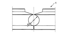
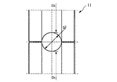
このステンレス鋼帯を幅79.3mmにスリット加工し、図1に示すように鋼帯2の板幅方向と平行に配置された直径8mmの小径曲げロール3で鋼帯2の長手方向に連続的に曲げ・曲げ戻し加工を施した。曲げ・曲げ戻し加工で発生した板幅方向の反りを利用して鋼帯2を円筒状に成形し、スクイズロール6で断面をほぼ真円状に保持した状態で、鋼帯2の板幅方向両端部を溶接速度10m/分で突合せTIG溶接した。スクイズロール6としては、図3に示すように直径ds =25.4mmのギャップを形成するロール対を使用した。
【0011】
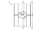
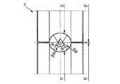
引き続き、溶接部から管底部までの距離が目標製品外径25.4mmよりも小さくなるように、オーバベンドロール9により溶接素管8を扁平加工した。オーバベンドロール9には、図4に示すカリバー半径RB=15.5mm,ロール底径D1=60mm,ロール胴径D2=82mmのロール対を使用した。また、適正扁平量に対応したカリバーをもつオーバベンドロール9として、図5に示すようにカリバーの長半径RB1=16.04mm,短半径RB2=11.03mm,ロール底径D1=60mm,ロール胴径D2=82.4mmのロール対を使用した。なお、図4のロールは、ロール合せ部で管と接触しない領域が生じる。図5のロールでは、総型でほぼ円周方向全体にわたって管表面に接触する。この点、図5のロールの方がロール合わせ部での局部的な折れ変形が生じないことから、図5のロールの方が好ましい。
扁平加工後の溶接素管8を引抜き装置10で引き抜いた後、直径方向の絞り加工を加えない状態で矯正ロール11により溶接素管8をほぼ真円形状に成形した。矯正ロール11としては、図6に示すように直径dc=25.4mmのギャップを形成する底径D3=60mmのロール対を使用した。
成形後の溶接素管8を定寸切断し、直径25.4mmの製品溶接管を得た。
【0012】
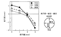
扁平加工に際し、扁平量を0mmから3mmまで変化させ、定寸切断された製品溶接管の先端,中央及び後端における真円度(縦径−横径)を測定した。
図7の測定結果にみられるように、扁平加工を施さない製品溶接管では、真円度が管外径の4%を超える値となっていた。扁平量0の条件は、表1のNo.1と異なり、扁平ロールの圧下を0としたものであるので、溶接部のルーフィング形状がそのまま残留し、管中央が極端な縦長となったものである。通常、中央の真円度がある程度確保された場合は、管端の形状が崩れる場合が多い。しかし、このような極端な条件の場合では、残留応力のバランスにより管端が依然として縦長ではあるものの、極端に縦長な中央に対しては縦長の程度が減少する方向に変形したものと推察される。
他方、扁平加工した製品溶接管では、何れの位置においても扁平量の増大に伴って管断面が縦長から横長となる傾向がみられた。なかでも、扁平量がおおよそ1.5〜2mmの範囲で扁平加工すると、先端,中央及び後端の何れにおいても真円度が管外径の1%程度以内の良好な形状をもつ製品溶接管が得られた。1.5〜2mmの扁平量は、目標製品外径の5.9〜7.9%に相当する。
【0013】
扁平量の増大に従って縦長から横長に変化する割合は、図8に示されているように、先端及び後端に比較して管中央で大きい。そのため、先端及び後端における真円度を確保するように扁平量を設定すると、管中央では過度に扁平化された横長になる虞れがある。
そこで、扁平量を2mmに固定して矯正ロール11を最大0.15mmまで圧下することにより、溶接素管8の直径を絞る加工を施した。この場合、図8に示すように圧下量の増大に伴って製品溶接管の中央が横長から縦長になり、先端及び後端では縦長から横長になる傾向がみられた。この結果から、扁平加工によるとき管中央部分及び管端部の断面形状が同時に所望の範囲に納まらない場合でも、矯正ロール11による圧下量調整を扁平加工に組み合わせることにより、長手方向に関してほぼ同じ断面形状をもつ製品溶接管が得られることが判る。
扁平量と矯正ロール11の圧下量との適正な関係は、各ロールの直径,ロールスタンドの配置,直径,板厚等の管の寸法,材料特性等の要因によって残留応力自体の大きさが変化することから一概に定めることができない。そのため、両者の関係を実験的に求めることが必要であるが、実施した条件下では扁平量については管外径の3〜10%程度,矯正ロール11の圧下による管直径の絞り量については管外周長の0〜0.5%程度であった。
【0014】
【発明の効果】
以上に説明したように、本発明においては、溶接素管を扁平加工した後で矯正ロールにより真円形状に成形することにより、造管時の残留応力が除去され、溶接素管を切断して製品溶接管とした場合に管端においても真円度が低下することがない。そのため、残留応力除去焼鈍を必要とせず、全長にわたって良好な断面形状をもつ溶接管が安価に製造される。
【図面の簡単な説明】
【図1】 本発明実施例で採用したロールレスフォーミング法による造管ライン
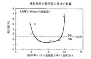
【図2】 成形条件が真円度に及ぼす影響
【図3】 図1の造管ラインにおけるスクイズロールのプロフィール
【図4】 同造管ラインにおけるオーバベンドロールのプロフィール
【図5】 同造管ラインにおける他のオーバベンドロールのプロフィール
【図6】 同造管ラインにおける矯正ロールのプロフィール
【図7】 扁平量が製品溶接管の真円度に及ぼす影響
【図8】 矯正ロールの圧下量が製品溶接管の真円度に及ぼす影響
【符号の説明】
1:アンコイラ 2:金属帯(鋼帯) 3:小径ロール 4:サイドロール 5:シームガイドロール 6:スクイズロール 7:溶接装置
8:溶接素管 9:オーバベンドロール 10:引抜き装置 11:矯正ロール 12:切断装置
ds :スクイズロールのクラウン直径
RB ,RB1,RB2:オーバベンドロールのカリバー半径
D1 :オーバベンドロールの底径 D2 :オーバベンドロールの胴径
dc :矯正ロールのクラウン直径 D3 :矯正ロールの底径[0001]
[Industrial application fields]
The present invention relates to a method for manufacturing a welded pipe having excellent roundness over the entire length including the pipe end.
[0002]
[Prior art]
When manufacturing a welded pipe by a roll forming method, a metal strip slit to a predetermined width is used as a pipe material. The metal strip is sequentially bent in the width direction by each of the forming stands arranged in multiple stages, and finally formed into a cylindrical shape in which both end portions in the width direction are abutted. Next, both end portions in the width direction are butt welded to obtain a raw pipe. The raw tube is passed through a sizing process, and the diameter of the tube is reduced by a plurality of stages of forming rolls to improve dimensional accuracy and roundness. After that, it is cut into a fixed size and becomes a product tube.
The roll forming method requires a multi-stage arrangement of forming stands. In addition, if the diameters of the tubes to be manufactured are different, it is required to change the forming rolls of the respective stands accordingly. Changing the forming rolls and adjusting each stand is a very troublesome operation, and becomes a bottleneck in improving productivity.
Therefore, the present inventors have developed a rollless forming method that does not require a large number of forming rolls by utilizing the property that the metal band curls in the plate width direction when bending / unbending strain is applied to the metal band ( Japanese Patent Publication No. 6-77773). This method uses a bending roll with a small diameter parallel to the plate width direction to continuously bend and unbend the metal strip with the inner surface of the tube facing inward, and use the bending in the plate width direction by bending and unbending. Then, the metal strip is formed into a cylindrical shape.
[0003]
[Problems to be solved by the invention]
In pipe making by the roll forming method, the curvature of the roll surface varies depending on the circumferential position of the pipe in contact with the roll surface. Therefore, depending on the circumferential position of the tube, the form of processing received by the forming roll, the amount of distortion, and the like vary. The welded pipe that has undergone such a molding process has a stress distribution with variation along the pipe circumferential direction, and when the pipe is cut, the cross-sectional shape of the cut end surface changes due to residual stress, resulting in the pipe end. Reduce the roundness of the part. In particular, when the welded tube to be manufactured is a thin tube having a small thickness ratio (thickness / tube outer diameter) or a tube made of a high-strength material, the tendency for the roundness to decrease becomes remarkable. Even when the pipe is formed by the rollless forming method, the roundness is still lowered at the end of the pipe, although not as much as the roll forming method.
The present invention has been devised to solve such a problem, and the residual stress is released by flattening after welding, and deformation due to the residual stress is suppressed even at the end of the pipe, and the roundness is high. The purpose is to produce welded pipes.
[0004]
[Means for Solving the Problems]
In order to achieve the object, the welded pipe manufacturing method of the present invention bends a metal strip in the plate width direction, butt welds both ends in the plate width direction with the cross-section held in a substantially circular shape, and then welds. The welded pipe is flattened with an overbend roll so that the distance from the base to the pipe bottom becomes smaller than the target product outer diameter, and the welded pipe is then converted into the formula (1) according to the flattening rate of the overbend roll. The diameter squeezing rate by the straightening roll is adjusted so that the numerical value given by 5 is in the range of 5 to 11, and it is formed into a substantially perfect circle shape by the straightening roll.
Flatness ratio (%) + 10 x diameter drawing ratio (%) (1)
However, the flattening ratio is expressed as (weld tube diameter−height after flattening) / weld tube diameter × 100 (%), and the diameter reduction ratio is (weld tube diameter−corrected diameter) / weld tube diameter × 100 (%) .
In flattening, it is preferable to flatten the welded pipe so that the distance from the welded portion to the tube bottom is 3 to 10% smaller than the target product outer diameter.
[0005]
[Embodiment]
In pipe forming by the roll forming method, a metal strip is sequentially bent in the plate width direction at each forming stand and formed into a cylindrical shape. In the rollless forming method shown in FIG. 1, the
The
[0006]
In any of the roll forming method and the rollless forming method, the form and size of distortion generated in the process of forming the
The residual stress is in a balanced state at a location away from the tube end. Therefore, when the correction condition by the
[0007]
In the present invention, in order to prevent the deformation resulting from the collapse of the balance state of the residual stress, the
As for the caliber shape, it is difficult to flatten the caliber with a radius equal to the target product radius, so it is necessary to make the caliber have a radius larger than the target product radius. Specifically, a desired flat deformation can be performed with a caliber having a radius of about 1 to 1.4 times the target product radius.
In order to secure a good roundness of the pipe in combination with a diameter drawing process using a straightening roll carried out following the flattening, the flattening is performed in the range of 3 to 10% of the welded pipe diameter as shown in Table 1. It is necessary to adjust the rate and further regulate the numerical value given by the equation (1) within the range of 5 to 11.
Flatness ratio (%) + 10 × diameter drawing ratio (1)
[0008]
[0009]
When the flatness is out of the range of 3 to 10% of the welded pipe diameter or the numerical value given by the expression (1) is out of the range of 5 to 11, the roundness deteriorates as shown in FIG. In addition, the cross section of the tube immediately after welding has a strength called the roofing due to the residual stress because the weld is hot and the strength is lower than other parts. In this case, a vertically long cross-sectional shape is obtained. Therefore, in the flat direction, it is necessary to squeeze the pipe after welding from above and below to form a horizontally long shape, and to improve the overall cross section of the pipe and the shape near the weld.
When the welded
The effect of flattening on the improvement of roundness shows different tendencies at the center, tip, and rear end of the product welded pipe. That is, as the flattening amount increases, the necessary roundness is maintained at the end of the tube, but there is a possibility that the tube is excessively flattened at the center of the tube. In such a case, the roundness at the center of the pipe is also ensured by applying a process of reducing the diameter of the welded
[0010]
【Example】
As tube materials, C: 0.065 wt%, Si: 0.50 wt%, Mn: 0.30 wt%, P: 0.025 wt%, S: 0.001 wt%, Ni: 2.00 wt% %, Cr: 16.30% by weight, N: 0.010% by weight, plate thickness 0.35 mm, 0.2% proof stress 935 MPa, tensile strength 1170 MPa, elongation 9.0%, Vickers hardness HV380 High-strength stainless steel strip was used.
This stainless steel strip is slit to a width of 79.3 mm and continuously in the longitudinal direction of the
[0011]
Subsequently, the welded
After the flattened welded
The formed welded
[0012]
During flattening, the flatness was changed from 0 mm to 3 mm, and the roundness (longitudinal diameter—lateral diameter) at the front, center, and rear ends of the product-welded pipe that had been cut to a fixed size was measured.
As can be seen from the measurement results in FIG. 7, the roundness of the product welded pipe not subjected to flattening was a value exceeding 4% of the outer diameter of the pipe. The condition of the
On the other hand, in the product welded pipe that was flattened, the cross section of the pipe tended to change from vertically long to horizontally long as the flattening amount increased at any position. In particular, when flattening is performed in a range where the flattening amount is approximately 1.5 to 2 mm, a product welded pipe having a good shape with a roundness within about 1% of the outer diameter of the pipe at any of the tip, center and rear end. was gotten. A flat amount of 1.5 to 2 mm corresponds to 5.9 to 7.9% of the target product outer diameter.
[0013]
As shown in FIG. 8, the rate of change from vertically long to horizontally long as the flat amount increases is larger at the center of the tube than at the front and rear ends. For this reason, if the flat amount is set so as to ensure the roundness at the front end and the rear end, there is a possibility that the flat center of the tube becomes excessively flat.
Therefore, the flattening amount was fixed to 2 mm and the straightening
The appropriate relationship between the flattening amount and the reduction amount of the straightening
[0014]
【The invention's effect】
As described above, in the present invention, after flattening the welded element pipe, it is formed into a perfect circle by a straightening roll, so that residual stress during pipe making is removed, and the welded element pipe is cut. In the case of a product welded pipe, the roundness does not decrease at the pipe end. Therefore, the residual stress removal annealing is not required, and a welded pipe having a good cross-sectional shape over the entire length is manufactured at a low cost.
[Brief description of the drawings]
FIG. 1 Pipe forming line by rollless forming method employed in the embodiment of the present invention FIG. 2 Influence of molding conditions on roundness FIG. 3 Profile of squeeze roll in the pipe forming line of FIG. ] Profiles of overbend rolls in the same pipe line [Fig. 5] Profiles of other overbend rolls in the pipe line [Figure 6] Profiles of straightening rolls in the pipe line [Figure 7] Flatness is the product weld pipe Effect on roundness of steel [Fig. 8] Effect of rolling reduction of straightening roll on roundness of product welded pipe [Explanation of symbols]
1: Uncoiler 2: Metal strip (steel strip) 3: Small diameter roll 4: Side roll 5: Seam guide roll 6: Squeeze roll 7: Welding device 8: Welding tube 9: Overbend roll 10: Pulling device 11: Straightening roll 12: Cutting device d s : Crown diameter R B , R B1 , R B2 of squeeze roll: Caliber radius of overbend roll D 1 : Bottom diameter of overbend roll D 2 : Body diameter d c of overbend roll: Straightening roll crown diameter D 3: bottom diameter of straightening rolls
Claims (2)
扁平率(%)+10×直径絞り率(%)・・・・(1)
ただし、扁平率は(溶接素管直径−扁平後の高さ)/溶接素管直径×100(%)で表し、直径絞り率は(溶接素管直径−矯正後直径)/溶接素管直径×100(%)で表す。 After bending the metal strip in the plate width direction and butt-welding both ends in the plate width direction with the cross-section held in a substantially circular shape, the distance from the welded portion to the tube bottom becomes smaller than the target product outer diameter The welding base pipe is flattened with an overbend roll, and the welding base pipe is then straightened so that the numerical value given by the formula (1) falls within the range of 5 to 11 in accordance with the flattening ratio of the overbend roll. A method for producing a welded pipe with excellent roundness, characterized by adjusting the diameter drawing ratio by using a straightening roll to form a substantially round shape.
Flatness ratio (%) + 10 x diameter drawing ratio (%) (1)
However, the flattening ratio is expressed as (weld tube diameter−height after flattening) / weld tube diameter × 100 (%), and the diameter reduction ratio is (weld tube diameter−corrected diameter) / weld tube diameter × 100 (%).
Priority Applications (1)
| Application Number | Priority Date | Filing Date | Title |
|---|---|---|---|
| JP06276297A JP3990761B2 (en) | 1997-03-17 | 1997-03-17 | Manufacturing method of welded pipe with excellent roundness |
Applications Claiming Priority (1)
| Application Number | Priority Date | Filing Date | Title |
|---|---|---|---|
| JP06276297A JP3990761B2 (en) | 1997-03-17 | 1997-03-17 | Manufacturing method of welded pipe with excellent roundness |
Publications (2)
| Publication Number | Publication Date |
|---|---|
| JPH10258312A JPH10258312A (en) | 1998-09-29 |
| JP3990761B2 true JP3990761B2 (en) | 2007-10-17 |
Family
ID=13209734
Family Applications (1)
| Application Number | Title | Priority Date | Filing Date |
|---|---|---|---|
| JP06276297A Expired - Fee Related JP3990761B2 (en) | 1997-03-17 | 1997-03-17 | Manufacturing method of welded pipe with excellent roundness |
Country Status (1)
| Country | Link |
|---|---|
| JP (1) | JP3990761B2 (en) |
Families Citing this family (4)
| Publication number | Priority date | Publication date | Assignee | Title |
|---|---|---|---|---|
| KR100956830B1 (en) | 2008-08-05 | 2010-05-07 | 주식회사 금강티더블유피 | Metal pipe forming device |
| KR101313805B1 (en) * | 2011-04-07 | 2013-10-01 | 오형동 | Manufacturing method and apparatus for aluminum tube |
| CN108188202B (en) * | 2017-12-29 | 2019-03-08 | 合肥实华管件有限责任公司 | A kind of shaping device of plate welded tube and concetrated pipe |
| CN114273447B (en) * | 2021-11-23 | 2022-10-11 | 杰森能源技术有限公司 | Method for manufacturing metal pipe |
-
1997
- 1997-03-17 JP JP06276297A patent/JP3990761B2/en not_active Expired - Fee Related
Also Published As
| Publication number | Publication date |
|---|---|
| JPH10258312A (en) | 1998-09-29 |
Similar Documents
| Publication | Publication Date | Title |
|---|---|---|
| AU2005285839B2 (en) | Plug, method of expanding inside diameter of metal pipe or tube using such plug, method of manufacturing metal pipe or tube, and metal pipe or tube | |
| KR910009151B1 (en) | Method for making thin-walled metal pipes | |
| WO2014192091A1 (en) | Method for producing welded steel pipe | |
| JP3990761B2 (en) | Manufacturing method of welded pipe with excellent roundness | |
| US4590781A (en) | Method for forming an electric resistance welded steel pipe | |
| JP2000271636A (en) | Forming die for manufacturing welded metal tube | |
| JP2018015799A (en) | Manufacturing method of steel pipe and steel pipe | |
| JPH07265941A (en) | Manufacture of welded tube excellent in workability by rolless tube manufacturing method | |
| JP3332217B2 (en) | Pipe forming method with bending roll | |
| JPS6150688B2 (en) | ||
| US20220193745A1 (en) | Rolling straightening machine and method of manufacturing a pipe or tube or a bar using same | |
| JP3946534B2 (en) | Manufacturing method of ERW steel pipe with excellent outer diameter shape | |
| JP6222126B2 (en) | ERW steel pipe and manufacturing method thereof | |
| JP3256162B2 (en) | Manufacturing method of welded steel pipe | |
| JP2018047506A (en) | Electroseamed steel pipe and manufacturing method thereof | |
| JPS62176611A (en) | Manufacture of thin metal tube | |
| JP3358654B2 (en) | Pipe forming method with bending roll | |
| JP4236918B2 (en) | Manufacturing method of plated steel pipe | |
| JP2820524B2 (en) | Bending roll | |
| RU2040988C1 (en) | Method of making welded straight-seam tubes | |
| JP3610824B2 (en) | Manufacturing method of thin welded pipe | |
| JPS63165021A (en) | Manufacture of electric welded steel pipe | |
| EP0133245A2 (en) | A method for forming an electric resistance welded steel pipe | |
| JPH07303907A (en) | Production of electric resistance welded steel tube excellent in roundness | |
| JP6252454B2 (en) | Manufacturing method of high-strength thick-walled ERW steel pipe |
Legal Events
| Date | Code | Title | Description |
|---|---|---|---|
| A521 | Written amendment |
Free format text: JAPANESE INTERMEDIATE CODE: A523 Effective date: 20040302 |
|
| A621 | Written request for application examination |
Free format text: JAPANESE INTERMEDIATE CODE: A621 Effective date: 20040302 |
|
| A977 | Report on retrieval |
Free format text: JAPANESE INTERMEDIATE CODE: A971007 Effective date: 20050407 |
|
| A131 | Notification of reasons for refusal |
Free format text: JAPANESE INTERMEDIATE CODE: A131 Effective date: 20060725 |
|
| A521 | Written amendment |
Free format text: JAPANESE INTERMEDIATE CODE: A523 Effective date: 20060921 |
|
| RD03 | Notification of appointment of power of attorney |
Free format text: JAPANESE INTERMEDIATE CODE: A7423 Effective date: 20070409 |
|
| RD04 | Notification of resignation of power of attorney |
Free format text: JAPANESE INTERMEDIATE CODE: A7424 Effective date: 20070417 |
|
| TRDD | Decision of grant or rejection written | ||
| A01 | Written decision to grant a patent or to grant a registration (utility model) |
Free format text: JAPANESE INTERMEDIATE CODE: A01 Effective date: 20070717 |
|
| A61 | First payment of annual fees (during grant procedure) |
Free format text: JAPANESE INTERMEDIATE CODE: A61 Effective date: 20070723 |
|
| FPAY | Renewal fee payment (event date is renewal date of database) |
Free format text: PAYMENT UNTIL: 20100727 Year of fee payment: 3 |
|
| R150 | Certificate of patent or registration of utility model |
Free format text: JAPANESE INTERMEDIATE CODE: R150 |
|
| FPAY | Renewal fee payment (event date is renewal date of database) |
Free format text: PAYMENT UNTIL: 20100727 Year of fee payment: 3 |
|
| FPAY | Renewal fee payment (event date is renewal date of database) |
Free format text: PAYMENT UNTIL: 20110727 Year of fee payment: 4 |
|
| FPAY | Renewal fee payment (event date is renewal date of database) |
Free format text: PAYMENT UNTIL: 20110727 Year of fee payment: 4 |
|
| FPAY | Renewal fee payment (event date is renewal date of database) |
Free format text: PAYMENT UNTIL: 20120727 Year of fee payment: 5 |
|
| FPAY | Renewal fee payment (event date is renewal date of database) |
Free format text: PAYMENT UNTIL: 20130727 Year of fee payment: 6 |
|
| FPAY | Renewal fee payment (event date is renewal date of database) |
Free format text: PAYMENT UNTIL: 20140727 Year of fee payment: 7 |
|
| LAPS | Cancellation because of no payment of annual fees |

