JP3990105B2 - Control device for electromagnetic variable valve timing device - Google Patents
Control device for electromagnetic variable valve timing device Download PDFInfo
- Publication number
- JP3990105B2 JP3990105B2 JP2000373844A JP2000373844A JP3990105B2 JP 3990105 B2 JP3990105 B2 JP 3990105B2 JP 2000373844 A JP2000373844 A JP 2000373844A JP 2000373844 A JP2000373844 A JP 2000373844A JP 3990105 B2 JP3990105 B2 JP 3990105B2
- Authority
- JP
- Japan
- Prior art keywords
- value
- rotational phase
- stopper
- advance
- target value
- Prior art date
- Legal status (The legal status is an assumption and is not a legal conclusion. Google has not performed a legal analysis and makes no representation as to the accuracy of the status listed.)
- Expired - Fee Related
Links
Images


Description
【0001】
【発明の属する技術分野】
本発明は、電磁式可変バルブタイミング装置の制御装置に関し、詳しくは、電磁ブレーキを用いてクランクシャフトに対するカムシャフトの回転位相を変化させる構成の電磁式可変バルブタイミング装置の制御装置に関する。
【0002】
【従来の技術】
従来から、車両用エンジンにおいて、電磁ブレーキの摩擦制動によりクランクシャフトに対するカムシャフトの回転位相を進角変化させる構成のエンジンの電磁式可変バルブタイミング装置が知られている(特開平10−153104号公報参照)。
【0003】
前記電磁式可変バルブタイミング装置においては、回転位相を遅角方向に付勢するコイルばねを有すると共に、遅角方向への回転位相の変化を規制するストッパとを備え、前記コイルばねによる付勢力に抗する制動力を電磁ブレーキによって発生させることで、前記ストッパ位置(基準位置)から回転位相を進角変化させるようになっている。
【0004】
【発明が解決しようとする課題】
ところで、回転位相を前記ストッパ位置に戻す場合には、電磁ブレーキを構成する電磁コイルに対する通電を遮断すれば良いが、このときストッパ位置にまでコイルばねの付勢力で戻るため運動エネルギーが大きく、ストッパが当たったときに大きな当たり音が発生し、これが車室内の乗員にまで伝播し、乗員に不快感を与えてしまう可能性があった。
【0005】
本発明は上記問題点に鑑みなされたものであり、電磁式可変バルブタイミング装置において、ストッパで規制される基準位置にまで回転位相を戻すときに、大きな当たり音が発生することを回避できる制御装置を提供することを目的とする。
【0006】
【課題を解決するための手段】
そのため請求項1記載の発明では、電磁ブレーキの制動力によりクランクシャフトに対するカムシャフトの回転位相を進角変化させる構成であって、前記回転位相を遅角方向に付勢する弾性体と、前記遅角方向への回転位相の変化を規制するストッパとを備え、前記ストッパ位置からの回転位相の進角量の目標値に応じて演算されるフィードホワード分と、前記進角量の実際値と前記目標値との偏差に応じて演算されるフィードバック分とから、前記電磁ブレーキの制御信号を決定する電磁式可変バルブタイミング装置の制御装置において、前記フィードホワード分が、前記目標値が所定値を超える領域においては、前記実際値を前記目標値に制御するための要求値に設定され、前記目標値が前記所定値以下の領域においては、前記目標値よりも回転位相を進角させる値に設定されるよう構成した。
【0007】
かかる構成によると、目標値が所定値以下の領域においては、フィードホワード分のみで電磁ブレーキを制御させると、目標値よりも進角側に制御されることになり、この進角側への偏りをフィードバック制御で修正する必要が生じるため、フィードホワード分として目標値に対応する要求値を設定させる場合に比べて、遅角変化させて目標へ収束させるときの応答が遅れることになる。
【0008】
請求項2記載の発明では、電磁ブレーキの制動力によりクランクシャフトに対するカムシャフトの回転位相を進角変化させる構成であって、前記回転位相を遅角方向に付勢する弾性体と、前記遅角方向への回転位相の変化を規制するストッパとを備え、前記ストッパ位置からの回転位相の進角量の実際値を前記進角量の目標値に制御するためのフィードホワード分と、前記実際値と前記目標値との偏差に応じたフィードバック分とから、前記電磁ブレーキの制御信号を決定する電磁式可変バルブタイミング装置の制御装置において、前記目標値が前記ストッパの位置であるときに、前記制御信号に対して、前記制御信号を回転位相の進角側に補正する所定の進角補正値を付加するよう構成した。
【0009】
かかる構成によると、ストッパ位置を目標とするときに、電磁ブレーキの制御信号が強制的に回転位相の進角側にシフトし、この余分な制御信号の進角側への変化分をフィードバック補正で吸収することになるため、目標値に向けて遅角変化させるときの応答が遅れることになる。請求項3記載の発明では、電磁ブレーキの制動力によりクランクシャフトに対するカムシャフトの回転位相を進角変化させる構成であって、前記回転位相を遅角方向に付勢する弾性体と、前記遅角方向への回転位相の変化を規制するストッパとを備え、前記ストッパ位置からの回転位相の進角量の実際値を前記進角量の目標値に制御するためのフィードホワード分と、前記実際値と前記目標値との偏差の積分値に応じた積分分を少なくとも含んで演算されるフィードバック分とから、前記電磁ブレーキの制御信号を決定する電磁式可変バルブタイミング装置の制御装置において、前記目標値が前記ストッパの位置になった初回において、前記偏差の積分値に所定の進角補正値を付加することで、前記積分分を回転位相の進角側に補正するよう構成した。
【0010】
かかる構成によると、目標値が前記ストッパの位置になった初回において、偏差の積分値を進角側に補正して、積分分を回転位相の進角側に補正するので、ストッパ位置に向けた遅角変化の速度が遅くなる。請求項4記載の発明では、前記目標値が前記ストッパの位置で、かつ、前記実際値が所定値以下であることを条件に、前記所定の進角補正値による補正を行う構成とした。
【0011】
かかる構成によると、目標値がストッパの位置に切り換わった時点から実際値が所定値以下になるまでの間は、通常にフィードバック制御を行わせ、実際値が所定値以下になってから、目標のストッパ位置になるまでの間で、進角補正値による補正によって遅角変化の遅れを生じさせる。請求項5記載の発明では、前記目標値が前記ストッパの位置で、かつ、前記目標値が前記ストッパの位置に切り換わってから所定時間以上経過していることを条件に、前記所定の進角補正値による補正を行う構成とした。
【0012】
かかる構成によると、目標値がストッパの位置に切り換わった時点から所定時間が経過するまでの間は、通常にフィードバック制御を行わせ、経過時間が所定時間になってからは、実際値がストッパ位置に充分に近づいているものと推定して、進角補正値による補正によって遅角変化に遅れを生じさせる。請求項6記載の発明では、前記所定の進角補正値を、回転位相を前記ストッパの位置にまで戻すときの戻し開始の回転位相に応じて設定する構成とした。
【0013】
かかる構成によると、回転位相をどの位置からストッパ位置まで戻すかによって進角補正値を変化させる。
【0014】
【発明の効果】
請求項1記載の発明によると、フィードホワード分が進角側にずれて設定されることで、遅角変化させて目標へ収束させるときの応答が遅れ、特にストッパ位置を目標とするときにストッパ位置に向かう速度が遅くなることで、ストッパの当たり音を小さくすることができるという効果がある。
【0015】
請求項2記載の発明では、ストッパ位置を目標とするときに制御信号が進角補正され、この余分な制御信号をフィードバック制御で吸収する必要があるため、ストッパ位置に向かう遅角変化の速度が遅くなり、以って、ストッパの当たり音を小さくすることができるという効果がある。
請求項3記載の発明によると、ストッパ位置を目標とするときに偏差の積分値が進角制御側に修正されることで、この余分な積分結果を吐き出す必要が生じ、これによってストッパ位置に向かう遅角変化の速度が遅くなり、以って、ストッパの当たり音を小さくすることができるという効果がある。
【0016】
請求項4,5記載の発明によると、目標がストッパ位置に切り換わった直後は通常に制御を行わせ、実際の回転位相がストッパ位置に近づいてから、遅れを生じさせるようにでき、目標への収束を過剰に遅らせることなく、ストッパの当たり音を小さくすることができるという効果がある。
請求項6記載の発明によると、当たり音が比較的小さい進角量の小さい状態からの戻し時に過剰に目標への収束が遅れることがなく、かつ、当たり音が比較的大きくなる進角量の大きい状態からの戻し時には、確実にストッパの当たり音を小さくすることができるという効果がある。
【0017】
【発明の実施の形態】
以下に本発明の実施の形態を説明する。
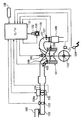
図1は実施の形態におけるエンジンのシステム構成図である。
この図1において、車両に搭載されるエンジン101の各気筒の燃焼室には、エアクリーナ102,吸気通路103,モータ104aで開閉駆動される電子制御式スロットル弁104を介して空気が吸入される。
【0018】
各気筒の燃焼室内に燃料(ガソリン)を直接噴射する電磁式の燃料噴射弁105が設けられており、該燃料噴射弁105から噴射される燃料と吸入空気とによって燃焼室内に混合気が形成される。
燃料噴射弁105は、コントロールユニット131から出力される噴射パルス信号によりソレノイドに通電されて開弁し、所定圧力に調圧された燃料を噴射する。
【0019】
そして、噴射された燃料は、吸気行程噴射の場合は燃焼室内に拡散して均質な混合気を形成し、また圧縮行程噴射の場合は点火栓106回りに集中的に層状の混合気を形成する。燃焼室内に形成される混合気は、点火栓106により着火燃焼する。
但し、エンジン101を上記の直接噴射式ガソリンエンジンに限定するものではなく、吸気ポートに燃料を噴射する構成のエンジンであっても良い。
【0020】
エンジン101からの排気は排気通路107より排出され、該排気通路107には排気浄化用の触媒108が介装されている。
また、吸気バルブ109を駆動する吸気側カムシャフト110には、電磁ブレーキの摩擦制動によりクランクシャフト112に対するカムシャフト110の回転位相を進角変化させ、作動角一定のまま吸気バルブ109のバルブタイミングを変更する電磁式可変バルブタイミング装置115が備えられている。
【0021】
尚、電磁式可変バルブタイミング装置115は、排気側カムシャフトに備えられる構成であっても良いし、また、排気側カムシャフトと吸気側カムシャフトの双方に備えられる構成であっても良いし、更に、シングルカムに適用される構成であっても良い。
コントロールユニット131は、CPU,ROM,RAM,A/D変換器及び入出力インターフェイス等を含んで構成されるマイコンを備え、各種センサからの入力信号を受け、これらに基づいて演算処理して、燃料噴射弁105,点火栓106及び前記電磁式可変バルブタイミング装置115を制御する。
【0022】
前記各種センサとして、エンジン101のクランク角を検出するクランク角センサ121、カムシャフト110から気筒判別信号を取り出すカムセンサ122が設けられており、前記クランク角センサ121からの信号に基づきエンジン101の回転速度Neが算出される。
この他、吸気通路103のスロットル弁104上流側で吸入空気流量Q(質量流量)を検出するエアフローメータ123、アクセルペダルの踏込み量(アクセル開度)APSを検出するアクセルセンサ124、スロットル弁104の開度TVOを検出するスロットルセンサ125、エンジン101の冷却水温Twを検出する水温センサ126、排気中の酸素濃度に応じて燃焼混合気の空燃比を検出する空燃比センサ127、車速VSPを検出する車速センサ128などが設けられている。
【0023】
ここで、前記電磁式可変バルブタイミング装置115の構造を、図2,3に基づいて説明する。
尚、電磁式可変バルブタイミング装置115は、電磁ブレーキの摩擦制動によりクランクシャフトに対するカムシャフトの回転遅延を制御して、クランクシャフトに対するカムシャフトの回転位相を変化させる構成であれば良く、図2,3に示すように第1の電磁ソレノイド及び第2の電磁ソレノイドを備える構成である必要はない。
【0024】
図2,3において、シリンダヘッド120に対して回転可能に支持されるカムシャフト110の端部111の軸周に回転可能にプーリ(又はスプロケット)2が支承される。プーリ2はカムシャフト110に対して相対回転可能に支承され、エンジン101のクランクシャフト112の回転に連動して回転する。
カムシャフト110の端部111の延長線上には、軸周にギヤが形成される伝達部材3がボルト31により固定され、プーリ2の回転が、以下に説明する伝達機構を介して伝達部材3に伝えられる。
【0025】
カムシャフト110と同軸に、フランジを有する筒状のドラム41が設けられ、このドラム41とプーリ2との間には、ドラム41の回転位相を遅らせる方向に付勢するコイルばね42(弾性体)が介装されている。
即ち、プーリ2にはケース部材44が固定され、コイルばね42の外周側端部は、このケース部材44の内周面部分に固定され、コイルばね42の内周側端部は、ドラム41の外周面に固定されている。
【0026】
ここで、前記ドラム41に形成されたストッパ41aと、前記プーリ2に形成されたストッパ2aとが当接して、コイルばね42による付勢方向(回転位相を遅らせる方向)への回転位相の変化が規制されるようになっており、後述する電磁ブレーキの摩擦制動力によって前記ストッパ位置(以下、基準位置という)から回転位相が進角方向に変化し、電磁ブレーキによる摩擦制動力が無くなると、コイルばね42の付勢力によって前記基準位置にまで戻るようになっている。
【0027】
また、伝達部材3の軸周に形成されたギア32と、筒状のピストン部材43の内周に形成されたギア433とが、はす歯ギヤによるヘリカル機構により噛み合っている。
ピストン部材43の外周面の対向する2箇所に、係合部431,431が突出形成されていて、プーリ2の回転中心部分からカムシャフト110の軸方向に延出している爪部材21,21の間に前記係合部431,431が係合している。この係合によりピストン部材43とプーリ2とは同位相で回転する。
【0028】
ピストン部材43の前記係合部431,431には、ピストン部材43の軸を中心とする雄ねじ432が各々形成され、ドラム41の内周面には雌ねじ411が形成されていて、この両者はねじ作用により噛み合っている。
ドラム軸受部材45は、伝達部材3の外周とドラム41の内周との間に介装され、この両者の相対回転を軸受する。このドラム軸受部材45とドラム41の内周面との間には、爪受部材7aが介装されている。
【0029】
この爪受部材7aはドラム41の内周面に支持され、爪部材21,21の先端部の外周面側に形成されている段部22,22に当接して、カムシャフト110の径方向に爪部材21,21を係止している。
被吸引部材46は、その回転中心部分に内歯の平ギヤ461が形成され、このギヤ461には、伝達部材3の先端部に形成されている平ギヤ33に噛み合っている。
【0030】
これにより、被吸引部材46は伝達部材3に対し、その軸方向に摺動可能に構成されると共に、被吸引部材46と伝達部材3とは同位相で回転する。
ドラム41のフランジ部分412の側面にはギア413が形成され、被吸引部材46の一方の面462に形成されているギア463と対峙していて、この両ギヤは噛み合うことで、ドラム41と被吸引部材46とが回転方向に係合するようにしてある。
【0031】
第1の電磁ソレノイド5bと第2の電磁ソレノイド5aは、カムシャフト110の軸芯線を囲むように、カムシャフト110の端部111に固定されている伝達部材3や、この伝達部材3を固定しているボルト31の外周面を囲むように軸受部材6を介して配置されている。
すなわち、スペーサ部材47が、ボルト31の頭部311と伝達部材3の先端部との間に嵌合固定されていて、このスペーサ部材47の外周側には、第2の電磁ソレノイド5aがスペーサ部材47との間に軸受部材6を介して配置されている。
【0032】
さらに、第2の電磁ソレノイド5aと被吸引部材46の外周側には、電磁ブレーキを構成する第1の電磁ソレノイド5bが配置されている。第2の電磁ソレノイド5aはボルト51aにより、ケース8に固定されている。
次に作用について説明する。
カムシャフト110の回転位相を進角側に変更するためには、第1の電磁ソレノイド5bが発生する磁界によりピストン部材43をカムシャフト110の軸方向に移動することにより行う。
【0033】
すなわち、まず、第2の電磁ソレノイド5aの発生磁界により、被吸引部材46が吸引されて、被吸引部材46のギア463と、ドラム41のギア413とが離れ、ドラム41がプーリ2に対して相対的に回転できるようにする。
そして、第1の電磁ソレノイド5bの発生磁界により、ドラム41を吸引することで、ドラム41を第1の電磁ソレノイド5bの端面に押し付けて、摩擦制動を作用させる。
【0034】
これにより、ドラム41はコイルばね42の付勢力に抗してプーリ2に対して回転遅れを生じて相対回転し、ねじ411とねじ432とで噛み合っているピストン部材43はカムシャフト110の軸方向に移動する。
ピストン部材43と伝達部材3とは前記のヘリカル機構により噛み合っているので、ピストン部材43の移動により、伝達部材3引いてはカムシャフト110の回転位相がプーリ2に対して進角側に変わることになる。
【0035】
従って、第1の電磁ソレノイド5bへの電流値を増大させ、コイルばね42の付勢力に抗する制動力(滑り摩擦)を増大させるほど、カムシャフト110の回転位相が進角側に変更されることになる。
上記のように、電磁ブレーキによる制動力に応じて決まるドラム41の回転遅れ量によってカムシャフト110の回転位相がプーリ2(クランクシャフト112)に対して変わるものであり、前記電磁ブレーキによる制動力は、第1の電磁ソレノイド5bに供給される電流値をデューティ制御することで制御されるようになっており、前記電流値の制御デューティDutyを変化させることで、回転位相の変化量(進角量)を連続的に制御できる。
【0036】
尚、本実施形態では、電磁ブレーキの制御信号に相当する制御デューティDuty(%)の増大に応じて、前記第1の電磁ソレノイド5bに供給される電流値が増大し、該電流値の増大に応じてカムシャフト110の回転位相が進角方向に変化するものとする。
前記コントロールユニット131は、後述するようにして、第1の電磁ソレノイド5bの通電をフィードバック制御してカムシャフト110の回転位相を変化させ、目標回転位相に一致すると、第2の電磁ソレノイド5aへの通電を遮断することで、被吸引部材46のギア463と、ドラム41のギア413とを噛み合わせ、ドラム41をプーリ2に対してそのときの位相状態で固定し、第1の電磁ソレノイド5bへの通電を遮断する。
【0037】
図4は、前記第1電磁ソレノイド5bの通電制御回路の第1実施形態を示すブロック図であり、フィードホワードデューティ演算部201には、エンジン負荷やエンジン回転速度などの運転条件に応じて設定される目標の回転位相(目標進角量)が入力され、該目標値に応じてフィードホワードデューティ(基本デューティ)を演算する。
【0038】
ここで、デューティ値の増大に比例して回転位相が進角変化するため、前記目標の回転位相に対するフィードホワードデューティの要求値は、図4中に点線で示すように比例関係となるが、本実施形態では、所定の回転位相(進角量)以下の領域で、前記要求値よりも大きな進角側にずれたフィードホワードデューティが設定されるようにしてある。
【0039】
前記目標値は、フィードバックデューティ演算部202にも入力され、該フィードバックデューティ演算部202では、前記クランク角センサ121及びカムセンサ122からの検出信号に基づいて検出される実際の回転位相θと前記目標値との偏差を演算し、更に、該偏差に基づく比例・積分・微分動作によってフィードバックデューティを演算する。
【0040】
尚、前記フィードバックデューティの演算を、比例・積分・微分動作の組み合わせに限定するものではなく、比例・積分動作で行わせる構成としても良く、また、スライディングモードを用いて行わせる構成としても良い。
そして、前記フィードバックデューティに前記フィードホワードデューティが加算され、該加算後のデューティが駆動回路203に出力される。
【0041】
前記駆動回路203は、入力されるデューティに応じて前記第1の電磁ソレノイド5bの通電を制御する。
上記構成において、前記フィードホワードデューティは、前述のように、目標が所定の回転位相(進角量)以下の領域で要求値よりも大きな値に設定されるから、そのままでは、目標よりも進角側に制御されることになり、該進角側へのずれがフィードバック制御で吸収されることになる。
【0042】
従って、フィードホワードデューティが要求値よりも大きな値に設定される領域の目標に向けて遅角制御するときには、目標への収束が遅れることになり、特に、目標を最遅角位置であるストッパ位置とするときには、ストッパ位置へ徐々に近づくことで、ストッパの当たり音を低減することができる。
図5は、前記第1電磁ソレノイド5bの通電制御回路の第2実施形態を示すブロック図であり、前記図4と同一要素には同一符号を付してある。
【0043】
この図5のブロックに示すフィードホワードデューティ演算部201では、各目標回転位相から要求されるフィードホワードデューティ、即ち、基本特性上でフィードホワードデューティを与えたときに目標回転位相になるようなデューティを設定する。
そして、フィードバックデューティ演算部202で演算されるフィードバックデューティに前記フィードホワードデューティが加算され、該加算後のデューティが駆動回路203に出力される。
【0044】
一方、進角補正値出力部204が設けられ、該進角補正値出力部204は、目標の回転位相が、最遅角位置であるストッパ位置(進角量=0)であるときに、駆動回路203に出力されるデューティを増大補正し、該増大補正分をフィードバック制御で吸収させるようにすることで、ストッパ位置に向かう回転位相の変化を遅らせ、以って、ストッパの当たり音を低減するようにしてある。
【0045】
図6のフローチャートは、前記進角補正値出力部204の処理動作を詳細に示すものである。
ステップS1では、目標の回転位相を読み込み、ステップS2では、前記目標の回転位相がストッパ位置(進角量=0)であるか否かを判別する。
そして、目標の回転位相がストッパ位置(進角量=0)であるときに、ステップS3へ進む。
【0046】
ステップS3では、実際の回転位相(進角量)が所定値以下であるか否かを判別し、目標がストッパ位置(進角量=0)であっても、実際の回転位相(進角量)が所定値以下でない場合には、補正処理を行うことなくそのまま本ルーチンを終了させる。
一方、目標がストッパ位置(進角量=0)で、かつ、実際の回転位相(進角量)が所定値以下である状態になると、ステップS4へ進み、駆動回路203に出力されるデューティを所定の進角補正値だけ増大補正する。
【0047】
上記構成により、目標がストッパ位置(進角量=0)に切り換わると、実際の回転位相(進角量)が所定値になるまでは、フィードバックデューティとフィードホワードデューティとから演算される通常のデューティが駆動回路203に出力されるが、実際の回転位相(進角量)が所定値以下になると、フィードバックデューティ+フィードホワードデューティ+進角補正値としてデューティが決定されるようになる。
【0048】
前記進角補正値は、回転位相を目標よりも進角させる方向に作用するから、フィードバック制御によってこれを吸収する補正がなされることになり、これによって、ストッパ位置に向かう遅角方向への回転位相の変化が遅れ、ストッパの当たり音が低減される。
更に、目標がストッパ位置(進角量=0)に切り換わっても、実際の回転位相が所定値以下になるまではデューティの補正がなされないので、その間は、比較的速い速度で回転位相を遅角変化させることができ、ストッパ位置に戻るときの応答が過剰に遅くなることを回避できる。
【0049】
但し、ステップS3を省略して、目標がストッパ位置(進角量=0)であるときに無条件に進角補正値を付加する構成としても良い。
尚、前記進角補正値は、固定値であっても良いが、図7に示すように、ストッパ位置に戻すときの戻し角度が大きいときほど、即ち、回転位相を変化代が大きいときほど大きくすると良い。
【0050】
前記戻し角度は、ストッパ位置に切り換わる前の目標回転位相、又は、目標の回転位相がストッパ位置に切り換わった時点での実際の回転位相、即ち、戻し開始時の回転位相から求められる。
また、ステップS3で実際の回転位相が所定以下になったか否かを判別させる代わりに、目標の回転位相がストッパ位置に切り換わってから所定時間以上経過しているか否かを判別させることで、間接的に実際の回転位相が所定値以下の状態になったか否を判別させる構成とすることもできる。
【0051】
上記構成においては、目標の回転位相がストッパ位置に切り換わってから実際の回転位相が所定値以下の状態になるまでの時間が、前記戻し角度によって異なるので、前記戻し角度が小さいときほど、前記所定時間をより短く変更すると良い。
図8は、前記第1電磁ソレノイド5bの通電制御回路の第3実施形態を示すブロック図であり、前記図4と同一要素には同一符号を付してある。
【0052】
この図8のブロックに示すフィードホワードデューティ演算部201では、目標回転位相から要求されるフィードホワードデューティ、即ち、基本特性上でフィードホワードデューティを与えたときに目標回転位相になるようなデューティを設定する。
一方、フィードバックデューティ演算部202では、積分分演算部202a,比例分演算部202b,微分分演算部202cが、それぞれ偏差の積分値,偏差,偏差の微分値に基づき積分分,比例分,微分分を演算し、これらの加算値としてフィードバックデューティを出力する。
【0053】
そして、前記フィードバックデューティに前記フィードホワードデューティを加算し、該加算後のデューティが駆動回路203に出力される。
また、偏差積分値補正部205が設けられ、該偏差積分値補正部205は、目標の回転位相が最遅角位置であるストッパ位置(進角量=0)であるときに、前記積分分演算部202aにおける偏差の積分値を、積分分が増大する方向に補正することで、ストッパ位置に向かう回転位相の変化を遅らせ、以って、ストッパの当たり音を低減するようにしてある。
【0054】
図9のフローチャートは、前記偏差積分値補正部205の処理動作を詳細に示すものである。
ステップS11では、目標の回転位相を読み込み、ステップS12では、前記目標の回転位相がストッパ位置(進角量=0)であるか否かを判別する。
そして、目標の回転位相がストッパ位置(進角量=0)であるときに、ステップS13へ進む。
【0055】
ステップS13では、実際の回転位相(進角量)が所定値以下であるか否かを判別し、目標がストッパ位置(進角量=0)であっても、実際の回転位相(進角量)が所定値以下でない場合には、補正処理を行うことなくそのまま本ルーチンを終了させる。
尚、第2の実施形態と同様に、ステップS13を省略しても良いし、また、ステップS13で目標がストッパ位置に切り換わってからの経過時間を判別させるようにしても良い。
【0056】
一方、目標がストッパ位置(進角量=0)で、かつ、実際の回転位相(進角量)が所定値以下である状態になると、ステップS14へ進み、ステップS12,13の条件が成立した初回時であるか否かを判別する。
条件成立の初回時であるときには、ステップS15へ進み、前記積分分演算部202aにおける偏差の積分値を、積分分が進角側に変化する方向に所定の進角補正量だけ補正する。
【0057】
尚、前記偏差の積分値の補正に用いる進角補正値は、第2の実施形態と同様に戻し角度に応じて変更すると良い。
上記のようにして、偏差の積分値が補正されると、積分分として目標よりも進角側にオフセット補正することになり、この余分な進角補正分の吐き出し行われる間、回転位相の遅角側への変化が遅れ、以って、ストッパの当たり音が低減されることになる。
【図面の簡単な説明】
【図1】実施の形態におけるエンジンのシステム構成図。
【図2】実施の形態における電磁式可変バルブタイミング装置の断面図。
【図3】実施の形態における電磁式可変バルブタイミング装置の分解斜視図。
【図4】回転位相制御の第1実施形態を示すブロック図。
【図5】回転位相制御の第2実施形態を示すブロック図。
【図6】上記第2実施形態における補正制御の詳細を示すフローチャート。
【図7】第2,3の実施形態に共通の補正値の特性図。
【図8】回転位相制御の第3実施形態を示すブロック図。
【図9】上記第3実施形態における補正制御の詳細を示すフローチャート。
【符号の説明】
2…プーリ
2a…ストッパ
3…伝達部材
5a…第2の電磁ソレノイド
5b…第1の電磁ソレノイド
41…ドラム
41a…ストッパ
42…コイルバネ
43…ピストン部材
46…被吸引部材
110…カムシャフト
101…エンジン
115…電磁式可変バルブタイミング装置
121…クランク角センサ
122…カムセンサ
131…コントロールユニット
201…フィードホワードデューティ演算部
202…フィードバックデューティ演算部
203…駆動回路
204…進角補正値出力部
205…偏差積分値補正部[0001]
BACKGROUND OF THE INVENTION
The present invention relates to a control device for an electromagnetic variable valve timing device, and more particularly to a control device for an electromagnetic variable valve timing device configured to change a rotational phase of a camshaft relative to a crankshaft using an electromagnetic brake.
[0002]
[Prior art]
2. Description of the Related Art Conventionally, in an engine for a vehicle, an electromagnetic variable valve timing device for an engine having a configuration in which the rotational phase of a camshaft relative to a crankshaft is advanced by friction braking of an electromagnetic brake is known (Japanese Patent Laid-Open No. 10-153104). reference).
[0003]
The electromagnetic variable valve timing device includes a coil spring that biases the rotational phase in the retarded direction, and a stopper that restricts the change of the rotational phase in the retarded direction, and is adapted to the biasing force of the coil spring. The rotational phase of the rotational phase is changed from the stopper position (reference position) by generating a braking force to be resisted by an electromagnetic brake.
[0004]
[Problems to be solved by the invention]
By the way, when the rotational phase is returned to the stopper position, it is only necessary to cut off the energization to the electromagnetic coil constituting the electromagnetic brake. At this time, the kinetic energy is large because the coil spring returns to the stopper position by the biasing force. When hitting, a loud hitting sound was generated, which propagated to the passengers in the passenger compartment and could cause discomfort to the passengers.
[0005]
The present invention has been made in view of the above problems, and in the electromagnetic variable valve timing device, a control device capable of avoiding a large hitting sound when returning the rotational phase to the reference position regulated by the stopper. The purpose is to provide .
[0006]
[Means for Solving the Problems]
Therefore, according to the first aspect of the present invention, the rotational phase of the camshaft relative to the crankshaft is advanced by the braking force of the electromagnetic brake, the elastic body biasing the rotational phase in the retarded direction, and the retarded phase. A stopper for restricting the change of the rotational phase in the angular direction, the feed forward amount calculated according to the target value of the advance amount of the rotational phase from the stopper position, the actual value of the advance amount, and the In the control device of the electromagnetic variable valve timing device that determines the control signal of the electromagnetic brake from the feedback calculated in accordance with the deviation from the target value , the target value exceeds the predetermined value by the feed forward amount. In the area, the required value for controlling the actual value to the target value is set. In the area where the target value is equal to or less than the predetermined value, the target value is set. And configured to also set the rotational phase to a value that is advanced.
[0007]
According to such a configuration, in a region where the target value is equal to or less than the predetermined value, if the electromagnetic brake is controlled only by the feed forward amount, the control is performed on the advance side with respect to the target value. Need to be corrected by feedback control, the response when the angle of change is made to converge to the target is delayed as compared with the case where the required value corresponding to the target value is set as the feedforward amount.
[0008]
According to a second aspect of the present invention, the rotational phase of the camshaft relative to the crankshaft is advanced by the braking force of the electromagnetic brake, the elastic body biasing the rotational phase in the retarded direction, and the retarded angle A stopper for restricting a change in the rotational phase in the direction, a feed forward amount for controlling the actual value of the advance amount of the rotational phase from the stopper position to the target value of the advance amount, and the actual value In the control device for an electromagnetic variable valve timing device that determines a control signal of the electromagnetic brake from a feedback amount corresponding to a deviation between the target value and the target value, the control is performed when the target value is the position of the stopper. A predetermined advance correction value for correcting the control signal to the advance side of the rotational phase is added to the signal.
[0009]
According to such a configuration, when the stopper position is targeted, the electromagnetic brake control signal is forcibly shifted to the advance side of the rotation phase, and the amount of change of the excess control signal to the advance side can be corrected by feedback correction. Since it absorbs, the response when changing the delay angle toward the target value is delayed. According to a third aspect of the present invention, the rotational phase of the camshaft relative to the crankshaft is advanced by the braking force of the electromagnetic brake, the elastic body biasing the rotational phase in the retarded direction, and the retarded angle. A stopper for restricting a change in the rotational phase in the direction, a feed forward amount for controlling the actual value of the advance amount of the rotational phase from the stopper position to the target value of the advance amount, and the actual value In the control device for an electromagnetic variable valve timing device that determines a control signal of the electromagnetic brake from a feedback component that is calculated including at least an integral corresponding to an integral value of a deviation from the target value, the target value in the first but became position of the stopper, by adding a predetermined advance angle correction value to the integral value of the deviation, to compensate for the integrated amount to the advance side of the rotational phase Form was.
[0010]
According to such a configuration, the first time when the target value becomes the position of the stopper, the integral value of the deviation is corrected to the advance side, and the integral is corrected to the advance side of the rotation phase. The rate of change in the retard angle becomes slower. According to a fourth aspect of the present invention, the correction by the predetermined advance correction value is performed on the condition that the target value is the position of the stopper and the actual value is not more than the predetermined value.
[0011]
According to such a configuration, a until the actual value from the time the target value is switched to the position of the stopper is equal to or less than a predetermined value, usually to perform the feedback control, the actual value falls below a predetermined value, the target Until the stopper position is reached, a delay change is delayed by the correction by the advance correction value. In the invention of claim 5, wherein, at the location of the target value is the stopper, and that the target value has passed a predetermined time after switched to the position of the stopper on condition, the predetermined lead angle It was set as the structure which correct | amends by a correction value.
[0012]
According to this configuration, the feedback control is normally performed until the predetermined time elapses from the time when the target value is switched to the stopper position, and after the elapsed time reaches the predetermined time, the actual value becomes the stopper value. It is estimated that the position is sufficiently close, and the delay angle change is delayed by the correction by the advance angle correction value. According to a sixth aspect of the invention, the predetermined advance angle correction value is set according to the rotational phase at the start of returning when the rotational phase is returned to the position of the stopper.
[0013]
According to this configuration, the advance correction value is changed depending on from which position the rotation phase is returned to the stopper position.
[0014]
【The invention's effect】
According to the first aspect of the present invention, the feed forward amount is set so as to be shifted toward the advance side, so that the response when the retard angle is changed and converged to the target is delayed, particularly when the stopper position is targeted. There is an effect that the hitting sound of the stopper can be reduced by reducing the speed toward the position.
[0015]
According to the second aspect of the present invention, when the stopper position is targeted, the advance angle of the control signal is corrected, and it is necessary to absorb this excess control signal by feedback control. There is an effect that the hitting sound of the stopper can be reduced.
According to the third aspect of the present invention, when the stopper position is targeted, the integrated value of the deviation is corrected to the advance angle control side, so that it is necessary to discharge this excess integration result, and this leads to the stopper position. There is an effect that the speed of the change in the retard angle becomes slow, and hence the hitting sound of the stopper can be reduced.
[0016]
According to the fourth and fifth aspects of the present invention, the control is normally performed immediately after the target is switched to the stopper position, and a delay can be caused after the actual rotational phase approaches the stopper position. There is an effect that the hitting sound of the stopper can be reduced without excessively delaying the convergence of.
According to the invention described in
[0017]
DETAILED DESCRIPTION OF THE INVENTION
Embodiments of the present invention will be described below.
FIG. 1 is a system configuration diagram of an engine according to an embodiment.
In FIG. 1, air is sucked into the combustion chamber of each cylinder of an
[0018]
An electromagnetic
The
[0019]
In the case of intake stroke injection, the injected fuel diffuses into the combustion chamber to form a homogeneous mixture, and in the case of compression stroke injection, a stratified mixture is intensively formed around the
However, the
[0020]
Exhaust gas from the
In addition, the
[0021]
The electromagnetic variable
The
[0022]
As the various sensors, a
In addition, an
[0023]
Here, the structure of the electromagnetic variable
The electromagnetic variable
[0024]
2 and 3, the pulley (or sprocket) 2 is rotatably supported on the shaft circumference of the
On the extension line of the
[0025]
A
That is, the
[0026]
Here, the
[0027]
Further, the
Engaging
[0028]
The engaging
The
[0029]
The claw receiving member 7 a is supported on the inner peripheral surface of the
The sucked
[0030]
Thus, the sucked
A
[0031]
The first
That is, the
[0032]
Further, the first
Next, the operation will be described.
In order to change the rotational phase of the
[0033]
That is, first, the attracted
Then, the
[0034]
Accordingly, the
Since the
[0035]
Accordingly, the rotational phase of the
As described above, the rotational phase of the
[0036]
In the present embodiment, as the control duty Duty (%) corresponding to the electromagnetic brake control signal increases, the current value supplied to the first
As will be described later, the
[0037]
FIG. 4 is a block diagram showing a first embodiment of the energization control circuit of the first
[0038]
Here, since the rotational phase changes in advance in proportion to the increase in the duty value, the required value of the feed forward duty with respect to the target rotational phase has a proportional relationship as shown by a dotted line in FIG. In the embodiment, the feed forward duty shifted to the advance side larger than the required value is set in a region below a predetermined rotational phase (advance amount).
[0039]
The target value is also input to a feedback
[0040]
The calculation of the feedback duty is not limited to a combination of proportional / integral / differential operations, but may be configured to be performed by proportional / integral operations, or may be performed using a sliding mode.
Then, the feed forward duty is added to the feedback duty, and the duty after the addition is output to the
[0041]
The
In the above configuration, the feed forward duty is set to a value larger than the required value in the region where the target is equal to or less than the predetermined rotational phase (advance amount) as described above. Therefore, the shift to the advance side is absorbed by feedback control.
[0042]
Therefore, when the retard control is performed toward the target in the region where the feed forward duty is set to a value larger than the required value, convergence to the target is delayed, and in particular, the target is the stopper position that is the most retarded position. In this case, by gradually approaching the stopper position, the hitting sound of the stopper can be reduced.
FIG. 5 is a block diagram showing a second embodiment of the energization control circuit of the first
[0043]
In the feed forward
Then, the feed forward duty is added to the feedback duty calculated by the feedback
[0044]
On the other hand, an advance correction
[0045]
The flowchart of FIG. 6 shows the processing operation of the advance correction
In step S1, a target rotational phase is read. In step S2, it is determined whether or not the target rotational phase is a stopper position (advance amount = 0).
Then, when the target rotation phase is the stopper position (advance amount = 0), the process proceeds to step S3.
[0046]
In step S3, it is determined whether or not the actual rotational phase (advance amount) is equal to or less than a predetermined value. Even if the target is the stopper position (advance amount = 0), the actual rotational phase (advance amount) is determined. ) Is not less than or equal to the predetermined value, this routine is terminated without performing correction processing.
On the other hand, when the target is the stopper position (advance amount = 0) and the actual rotational phase (advance amount) is equal to or less than the predetermined value, the process proceeds to step S4, and the duty output to the
[0047]
With the above configuration, when the target is switched to the stopper position (advance amount = 0), the normal operation calculated from the feedback duty and the feed forward duty until the actual rotational phase (advance amount) reaches a predetermined value. Although the duty is output to the
[0048]
Since the advance angle correction value acts in a direction to advance the rotation phase from the target, correction is performed to absorb this by feedback control, whereby rotation in the retard direction toward the stopper position is performed. The phase change is delayed, and the hitting sound of the stopper is reduced.
Furthermore, even if the target is switched to the stopper position (advance amount = 0), the duty is not corrected until the actual rotational phase becomes a predetermined value or less, so during that time the rotational phase is adjusted at a relatively high speed. The delay angle can be changed, and it is possible to avoid an excessively slow response when returning to the stopper position.
[0049]
However, step S3 may be omitted, and the advance angle correction value may be added unconditionally when the target is the stopper position (advance amount = 0).
The advance angle correction value may be a fixed value, but as shown in FIG. 7, the advance angle correction value is larger as the return angle when returning to the stopper position is larger, that is, as the rotation phase is larger. Good.
[0050]
The return angle is obtained from the target rotational phase before switching to the stopper position, or the actual rotational phase when the target rotational phase is switched to the stopper position, that is, the rotational phase at the start of return.
Further, instead of determining whether or not the actual rotational phase has become equal to or less than a predetermined value in step S3, by determining whether or not a predetermined time has elapsed since the target rotational phase has switched to the stopper position, It can also be configured to indirectly determine whether or not the actual rotational phase is in a state of a predetermined value or less.
[0051]
In the above configuration, the time from when the target rotational phase is switched to the stopper position until the actual rotational phase becomes a state equal to or less than a predetermined value varies depending on the return angle. It is better to change the predetermined time shorter.
FIG. 8 is a block diagram showing a third embodiment of the energization control circuit of the first
[0052]
In the feed forward
On the other hand, in the feedback
[0053]
Then, the feed forward duty is added to the feedback duty, and the duty after the addition is output to the
Further, a deviation integral
[0054]
The flowchart of FIG. 9 shows the processing operation of the deviation integral
In step S11, the target rotational phase is read. In step S12, it is determined whether or not the target rotational phase is the stopper position (advance amount = 0).
Then, when the target rotational phase is the stopper position (advance amount = 0), the process proceeds to step S13.
[0055]
In step S13, it is determined whether or not the actual rotational phase (advance amount) is equal to or less than a predetermined value. Even if the target is the stopper position (advance amount = 0), the actual rotational phase (advance amount) is determined. ) Is not less than or equal to the predetermined value, this routine is terminated without performing correction processing.
As in the second embodiment, step S13 may be omitted, or the elapsed time after the target is switched to the stopper position in step S13 may be determined.
[0056]
On the other hand, when the target is the stopper position (advance amount = 0) and the actual rotational phase (advance amount) is equal to or less than the predetermined value, the process proceeds to step S14, and the conditions of steps S12 and S13 are satisfied. It is determined whether it is the first time.
When it is the first time that the condition is satisfied, the process proceeds to step S15, and the integral value of the deviation in the
[0057]
The advance correction value used for correcting the deviation integral value may be changed according to the return angle as in the second embodiment.
When the integral value of the deviation is corrected as described above, an offset correction is made to the advance side of the target as an integral part, and the rotation phase is delayed while the extra advance correction part is discharged. The change to the corner side is delayed, so that the hitting sound of the stopper is reduced.
[Brief description of the drawings]
FIG. 1 is a system configuration diagram of an engine in an embodiment.
FIG. 2 is a cross-sectional view of the electromagnetic variable valve timing device according to the embodiment.
FIG. 3 is an exploded perspective view of the electromagnetic variable valve timing device according to the embodiment.
FIG. 4 is a block diagram showing a first embodiment of rotational phase control.
FIG. 5 is a block diagram showing a second embodiment of rotational phase control.
FIG. 6 is a flowchart showing details of correction control in the second embodiment.
FIG. 7 is a characteristic diagram of correction values common to the second and third embodiments.
FIG. 8 is a block diagram showing a third embodiment of rotational phase control.
FIG. 9 is a flowchart showing details of correction control in the third embodiment.
[Explanation of symbols]
2 ...
Claims (6)
前記フィードホワード分が、前記目標値が所定値を超える領域においては、前記実際値を前記目標値に制御するための要求値に設定され、前記目標値が前記所定値以下の領域においては、前記目標値よりも回転位相を進角させる値に設定されることを特徴とする電磁式可変バルブタイミング装置の制御装置。The configuration is such that the rotational phase of the camshaft relative to the crankshaft is advanced by the braking force of the electromagnetic brake, and an elastic body that urges the rotational phase in the retarded direction, and the change in rotational phase in the retarded direction. And a stopper for regulating, and calculating according to the deviation between the feed forward amount calculated according to the target value of the advance amount of the rotational phase from the stopper position and the actual value of the advance amount and the target value. In the control device of the electromagnetic variable valve timing device that determines the control signal of the electromagnetic brake from the amount of feedback to be performed ,
In the region where the target value exceeds the predetermined value , the feed forward amount is set to a request value for controlling the actual value to the target value, and in the region where the target value is equal to or less than the predetermined value, A control device for an electromagnetic variable valve timing device, wherein the control device is set to a value that advances the rotational phase from a target value .
前記目標値が前記ストッパの位置であるときに、前記制御信号に対して、前記制御信号を回転位相の進角側に補正する所定の進角補正値を付加することを特徴とする電磁式可変バルブタイミング装置の制御装置。The configuration is such that the rotational phase of the camshaft relative to the crankshaft is advanced by the braking force of the electromagnetic brake, and an elastic body that urges the rotational phase in the retarded direction, and the change in rotational phase in the retarded direction. A stopper for regulating, and a feed forward amount for controlling the actual value of the advance amount of the rotational phase from the stopper position to the target value of the advance amount, and the deviation between the actual value and the target value In the control device of the electromagnetic variable valve timing device that determines the control signal of the electromagnetic brake from the corresponding feedback amount ,
When the target value is the position of the stopper, a predetermined advance angle correction value for correcting the control signal to the advance side of the rotation phase is added to the control signal. Control device for valve timing device.
前記目標値が前記ストッパの位置になった初回において、前記偏差の積分値に所定の進角補正値を付加することで、前記積分分を回転位相の進角側に補正することを特徴とする電磁式可変バルブタイミング装置の制御装置。The configuration is such that the rotational phase of the camshaft relative to the crankshaft is advanced by the braking force of the electromagnetic brake, and an elastic body that urges the rotational phase in the retarded direction, and the change in rotational phase in the retarded direction. A stopper for regulating, a feed forward amount for controlling the actual value of the advance angle of the rotational phase from the stopper position to the target value of the advance angle, and the deviation between the actual value and the target value In a control device for an electromagnetic variable valve timing device that determines a control signal of the electromagnetic brake from a feedback component that is calculated including at least an integral component according to an integral value ,
In the first time when the target value becomes the position of the stopper , a predetermined advance correction value is added to the integrated value of the deviation to correct the integral to the advance side of the rotation phase. Control device for electromagnetic variable valve timing device.
Priority Applications (1)
| Application Number | Priority Date | Filing Date | Title |
|---|---|---|---|
| JP2000373844A JP3990105B2 (en) | 2000-12-08 | 2000-12-08 | Control device for electromagnetic variable valve timing device |
Applications Claiming Priority (1)
| Application Number | Priority Date | Filing Date | Title |
|---|---|---|---|
| JP2000373844A JP3990105B2 (en) | 2000-12-08 | 2000-12-08 | Control device for electromagnetic variable valve timing device |
Publications (3)
| Publication Number | Publication Date |
|---|---|
| JP2002180854A JP2002180854A (en) | 2002-06-26 |
| JP2002180854A5 JP2002180854A5 (en) | 2005-02-24 |
| JP3990105B2 true JP3990105B2 (en) | 2007-10-10 |
Family
ID=18843147
Family Applications (1)
| Application Number | Title | Priority Date | Filing Date |
|---|---|---|---|
| JP2000373844A Expired - Fee Related JP3990105B2 (en) | 2000-12-08 | 2000-12-08 | Control device for electromagnetic variable valve timing device |
Country Status (1)
| Country | Link |
|---|---|
| JP (1) | JP3990105B2 (en) |
Families Citing this family (2)
| Publication number | Priority date | Publication date | Assignee | Title |
|---|---|---|---|---|
| JP4708453B2 (en) * | 2008-05-26 | 2011-06-22 | 日立オートモティブシステムズ株式会社 | Control device for variable valve timing mechanism |
| DE112012007268T5 (en) * | 2012-12-28 | 2015-10-08 | Nittan Valve Co., Ltd. | A method and apparatus for controlling a phase change device |
-
2000
- 2000-12-08 JP JP2000373844A patent/JP3990105B2/en not_active Expired - Fee Related
Also Published As
| Publication number | Publication date |
|---|---|
| JP2002180854A (en) | 2002-06-26 |
Similar Documents
| Publication | Publication Date | Title |
|---|---|---|
| JP3603398B2 (en) | Control device for internal combustion engine | |
| KR100342840B1 (en) | Valve timing control system for internal combustion engine | |
| JP3668167B2 (en) | Valve timing control device for internal combustion engine | |
| JP4609278B2 (en) | Variable valve timing control device for internal combustion engine and internal combustion engine provided with the variable valve timing control device | |
| US7168410B2 (en) | Idle speed controller for internal combustion engine | |
| JPH06249044A (en) | Engine control device | |
| JP4291762B2 (en) | Engine stop control device and vehicle equipped with the same | |
| JP3627601B2 (en) | Engine intake air amount control device | |
| JP2006266200A (en) | Valve characteristic control device for internal combustion engine | |
| JP4011282B2 (en) | Control device for electromagnetic variable valve timing device | |
| US7753016B2 (en) | Control apparatus for internal combustion engine | |
| JP4914145B2 (en) | Variable valve control device for vehicle engine | |
| JPH04295111A (en) | Cam timing control device of engine | |
| JP3990105B2 (en) | Control device for electromagnetic variable valve timing device | |
| JP4078828B2 (en) | Control device for internal combustion engine | |
| JP4027589B2 (en) | Control device for electromagnetic variable valve timing device | |
| JP3771101B2 (en) | Control device for internal combustion engine | |
| US20220003181A1 (en) | Internal combustion engine control apparatus | |
| JP2010196532A (en) | Control device for vehicular internal combustion engine | |
| JP6585496B2 (en) | Control device for internal combustion engine | |
| JP5169876B2 (en) | Control device and control method for internal combustion engine | |
| JP2006316761A (en) | Torque control device for internal combustion engine | |
| JP2007298045A (en) | Control device for electromagnetic variable valve timing device | |
| JP7276589B2 (en) | CONTROL METHOD AND CONTROL DEVICE FOR INTERNAL COMBUSTION ENGINE | |
| JP3149724B2 (en) | Valve timing control device for internal combustion engine |
Legal Events
| Date | Code | Title | Description |
|---|---|---|---|
| A521 | Written amendment |
Free format text: JAPANESE INTERMEDIATE CODE: A523 Effective date: 20040323 |
|
| A621 | Written request for application examination |
Effective date: 20040323 Free format text: JAPANESE INTERMEDIATE CODE: A621 |
|
| A711 | Notification of change in applicant |
Effective date: 20041217 Free format text: JAPANESE INTERMEDIATE CODE: A712 |
|
| A977 | Report on retrieval |
Effective date: 20061129 Free format text: JAPANESE INTERMEDIATE CODE: A971007 |
|
| A131 | Notification of reasons for refusal |
Effective date: 20061205 Free format text: JAPANESE INTERMEDIATE CODE: A131 |
|
| A521 | Written amendment |
Effective date: 20070202 Free format text: JAPANESE INTERMEDIATE CODE: A523 |
|
| TRDD | Decision of grant or rejection written | ||
| A01 | Written decision to grant a patent or to grant a registration (utility model) |
Effective date: 20070626 Free format text: JAPANESE INTERMEDIATE CODE: A01 |
|
| A61 | First payment of annual fees (during grant procedure) |
Effective date: 20070719 Free format text: JAPANESE INTERMEDIATE CODE: A61 |
|
| FPAY | Renewal fee payment (prs date is renewal date of database) |
Free format text: PAYMENT UNTIL: 20100727 Year of fee payment: 3 |
|
| R150 | Certificate of patent (=grant) or registration of utility model |
Free format text: JAPANESE INTERMEDIATE CODE: R150 |
|
| LAPS | Cancellation because of no payment of annual fees |