JP7276589B2 - CONTROL METHOD AND CONTROL DEVICE FOR INTERNAL COMBUSTION ENGINE - Google Patents
CONTROL METHOD AND CONTROL DEVICE FOR INTERNAL COMBUSTION ENGINE Download PDFInfo
- Publication number
- JP7276589B2 JP7276589B2 JP2022501378A JP2022501378A JP7276589B2 JP 7276589 B2 JP7276589 B2 JP 7276589B2 JP 2022501378 A JP2022501378 A JP 2022501378A JP 2022501378 A JP2022501378 A JP 2022501378A JP 7276589 B2 JP7276589 B2 JP 7276589B2
- Authority
- JP
- Japan
- Prior art keywords
- valve
- timing
- intake
- vehicle
- pressure
- Prior art date
- Legal status (The legal status is an assumption and is not a legal conclusion. Google has not performed a legal analysis and makes no representation as to the accuracy of the status listed.)
- Active
Links
Images


Classifications
-
- F—MECHANICAL ENGINEERING; LIGHTING; HEATING; WEAPONS; BLASTING
- F02—COMBUSTION ENGINES; HOT-GAS OR COMBUSTION-PRODUCT ENGINE PLANTS
- F02D—CONTROLLING COMBUSTION ENGINES
- F02D23/00—Controlling engines characterised by their being supercharged
-
- F—MECHANICAL ENGINEERING; LIGHTING; HEATING; WEAPONS; BLASTING
- F02—COMBUSTION ENGINES; HOT-GAS OR COMBUSTION-PRODUCT ENGINE PLANTS
- F02D—CONTROLLING COMBUSTION ENGINES
- F02D29/00—Controlling engines, such controlling being peculiar to the devices driven thereby, the devices being other than parts or accessories essential to engine operation, e.g. controlling of engines by signals external thereto
- F02D29/02—Controlling engines, such controlling being peculiar to the devices driven thereby, the devices being other than parts or accessories essential to engine operation, e.g. controlling of engines by signals external thereto peculiar to engines driving vehicles; peculiar to engines driving variable pitch propellers
-
- F—MECHANICAL ENGINEERING; LIGHTING; HEATING; WEAPONS; BLASTING
- F02—COMBUSTION ENGINES; HOT-GAS OR COMBUSTION-PRODUCT ENGINE PLANTS
- F02D—CONTROLLING COMBUSTION ENGINES
- F02D43/00—Conjoint electrical control of two or more functions, e.g. ignition, fuel-air mixture, recirculation, supercharging or exhaust-gas treatment
-
- Y—GENERAL TAGGING OF NEW TECHNOLOGICAL DEVELOPMENTS; GENERAL TAGGING OF CROSS-SECTIONAL TECHNOLOGIES SPANNING OVER SEVERAL SECTIONS OF THE IPC; TECHNICAL SUBJECTS COVERED BY FORMER USPC CROSS-REFERENCE ART COLLECTIONS [XRACs] AND DIGESTS
- Y02—TECHNOLOGIES OR APPLICATIONS FOR MITIGATION OR ADAPTATION AGAINST CLIMATE CHANGE
- Y02T—CLIMATE CHANGE MITIGATION TECHNOLOGIES RELATED TO TRANSPORTATION
- Y02T10/00—Road transport of goods or passengers
- Y02T10/10—Internal combustion engine [ICE] based vehicles
- Y02T10/12—Improving ICE efficiencies
Description
この発明は、車両用内燃機関において、排気系に設けられた触媒の暖機が完了する前の未燃HCの排出を低減する技術に関し、特に、過給機を備えた内燃機関においてバルブタイミングを適切なものとする制御方法および制御装置に関する。 TECHNICAL FIELD The present invention relates to a technique for reducing unburned hydrocarbon emissions before a catalyst provided in an exhaust system completes warming up in a vehicle internal combustion engine, and more particularly to a technology for adjusting valve timing in an internal combustion engine equipped with a supercharger. Appropriate control method and control device.
特許文献1には、エンジンのバルブタイミング制御装置として、暖機運転中の極低温時にはバルブオーバラップをポジティブオーバラップ(プラスオーバラップとも呼ばれる)とし、極低温でないときにはネガティブオーバラップ(マイナスオーバラップとも呼ばれる)とするようにした構成が開示されている。また、始動時に排出される未燃HCを低減するために、点火時期をリタードしていわゆるリタード燃焼を行うことが開示されている。
この特許文献1は、排気弁側は開時期および閉時期が変化しない固定のバルブタイミングであり、吸気弁側の開時期および閉時期を可変バルブタイミング機構により進角・遅角させることでオーバラップ量を変化させている。 In
機関始動後、アイドル状態でリタード燃焼を行っている状態から車両の発進要求があると、要求負荷の上昇に伴って燃料量が増加する一方、触媒暖機が未完了であっても、出力確保のために、一般にリタード燃焼の終了もしくはリタード量の縮小がなされる。このような場合に、シリンダ壁面に付着した液膜に起因する未燃HCが排気弁を通して排気弁閉時期直前に押し出されてしまう(いわゆるHCの二次ピーク)ことにより、エンジンアウトHCの値が高くなる。特許文献1は、このようなHCの二次ピークに対処したものではない。 After the engine is started, when there is a request to start the vehicle from the retarded combustion state in the idling state, the amount of fuel increases as the required load rises. For this reason, retard combustion is generally terminated or the amount of retard is reduced. In such a case, the unburned HC caused by the liquid film adhering to the cylinder wall surface is pushed out through the exhaust valve just before the exhaust valve closing timing (so-called secondary peak of HC), and the engine-out HC value is reduced. get
この発明は、車両が触媒暖機完了前にアイドル状態から発進加速へと移行した場合にも二次ピークによるHC排出の悪化を最小限とし得る内燃機関の制御を提供することを目的としている。 SUMMARY OF THE INVENTION An object of the present invention is to provide control of an internal combustion engine capable of minimizing deterioration of HC emissions due to a secondary peak even when a vehicle shifts from an idling state to a starting acceleration before catalyst warm-up is completed.
この発明は、少なくとも排気弁側に可変動弁機構を有し、排気弁閉時期が上死点よりも遅くかつ吸気弁開時期に対してポジティブオーバラップとなる第1のバルブタイミングと、排気弁閉時期が上死点よりも早い第2のバルブタイミングと、に制御可能であるとともに、過給機を備えた車両用内燃機関の制御方法であって、
触媒が未暖機の触媒暖機運転中に、
過給が行われない低負荷側の第1の運転領域では第1のバルブタイミングとし、
過給が行われる高負荷側の第2の運転領域では第2のバルブタイミングとする。
好ましくは、車両停止中のアイドル時には第1のバルブタイミングとし、
車両の発進加速が行われ、吸気圧が大気圧近傍の所定の圧力閾値以上となるか、または、要求負荷が機関回転速度毎に予め設定された所定の負荷閾値以上となったら、第2のバルブタイミングに切り換える。
The present invention has a variable valve mechanism at least on the exhaust valve side, a first valve timing in which the exhaust valve closing timing is later than top dead center and positively overlaps the intake valve opening timing, and an exhaust valve. A control method for a vehicle internal combustion engine equipped with a supercharger and capable of controlling a second valve timing in which the closing timing is earlier than the top dead center, comprising:
During catalyst warm-up operation when the catalyst is not yet warmed up,
The first valve timing is set in the first operating region on the low load side where supercharging is not performed,
The second valve timing is set in the second operating region on the high load side where supercharging is performed.
Preferably, the first valve timing is set during idling while the vehicle is stopped,
When the vehicle is started and accelerated and the intake pressure becomes equal to or higher than a predetermined pressure threshold close to the atmospheric pressure, or the required load becomes equal to or higher than a predetermined load threshold set in advance for each engine rotation speed, the second Switch to valve timing.
過給が行われない第1の運転領域では、吸気圧つまり吸気弁上流の吸気通路内の圧力がいわゆる負圧であり、従って、第1のバルブタイミングの下での吸気弁開時期における筒内圧は吸気圧よりも高く、吸気弁が開いたときに筒内圧が急激に低下する。そのため、上死点直前付近でいわゆる二次ピークとして開弁中の排気弁を通して排気ポートへ押し出されていたHCの少なくとも一部が、吸気弁が開いたときに燃焼室内へ引き戻され、さらにその一部は吸気ポートへと吸い出される。これらの燃焼室内あるいは吸気ポートへ戻ったHCは、以後の燃焼サイクルで燃焼される。このような吸入負圧による引き戻し作用により、第1の運転領域例えばアイドル時におけるHCの二次ピークが抑制される。 In the first operating region where supercharging is not performed, the intake pressure, that is, the pressure in the intake passage upstream of the intake valve is a so-called negative pressure. is higher than the intake pressure, and the in-cylinder pressure drops rapidly when the intake valve opens. Therefore, at least part of the HC, which has been pushed out to the exhaust port through the open exhaust valve as a so-called secondary peak near the top dead center, is pulled back into the combustion chamber when the intake valve is opened. The part is aspirated into the intake port. These HCs returned to the combustion chamber or intake port are burned in subsequent combustion cycles. Due to such a pullback action by the intake negative pressure, the secondary peak of HC in the first operating region, for example, during idling is suppressed.
一方、高負荷側の第2の運転領域では、過給により吸気圧が高くなるので、上述した排気ポートから燃焼室内あるいは吸気ポートへの引き戻し作用が得られない。この第2の運転領域では、第2のバルブタイミングとなり、排気弁が上死点よりも早期に閉じることで、二次ピークによるHCの排出が抑制される。従って、例えば触媒暖機中にアイドル状態からアクセルを踏み込んで発進加速したようなときのHCの増加が抑制される。 On the other hand, in the second operating region on the high load side, the intake pressure increases due to supercharging, so the above-described pullback action from the exhaust port to the combustion chamber or the intake port cannot be obtained. In this second operating region, the second valve timing is set, and the exhaust valve closes earlier than the top dead center, thereby suppressing HC emissions due to the secondary peak. Therefore, an increase in HC is suppressed when, for example, the accelerator is depressed from an idling state during catalyst warm-up to start acceleration.
以下、この発明の一実施例を図面に基づいて詳細に説明する。図1は、この発明の一実施例の制御が適用される車両用内燃機関1の概略的な構成を示す説明図である。内燃機関1は、図示せぬトルクコンバータおよび有段もしくは無段の自動変速機と組み合わされて車両に搭載されており、図示せぬ終減速装置を介して車両の駆動輪を駆動している。 An embodiment of the present invention will be described in detail below with reference to the drawings. FIG. 1 is an explanatory diagram showing a schematic configuration of a vehicle
内燃機関1は、例えばガソリンを燃料とする4ストロークサイクルの火花点火式内燃機関であって、ピストン2によって形成される燃焼室3の天井壁面に、一対の吸気弁4および一対の排気弁5が配置されているとともに、これらの吸気弁4および排気弁5に囲まれた中央部に点火プラグ6および燃料噴射弁7が配置されている。 The
上記燃料噴射弁7は、駆動パルス信号が印加されることによって開弁する電磁式ないし圧電式の噴射弁であって、駆動パルス信号のパルス幅に実質的に比例した量の燃料を筒内へ噴射する。なお、本発明においては、吸気弁4上流側の吸気ポート8内に燃料を噴射するポート噴射式機関として構成したものであってもよい。 The fuel injection valve 7 is an electromagnetic or piezoelectric injection valve that opens when a drive pulse signal is applied, and injects fuel into the cylinder in an amount substantially proportional to the pulse width of the drive pulse signal. Inject. The present invention may be configured as a port injection engine that injects fuel into the intake port 8 on the upstream side of the intake valve 4 .
上記吸気ポート8に接続された吸気通路9のコレクタ部9a上流側には、エンジンコントローラ10からの制御信号によって開度が制御される電子制御型スロットルバルブ11が介装されており、さらにその上流側に、ターボ過給機12のコンプレッサ12Aが配設されている。このコンプレッサ12Aの上流側に、吸入空気量を検出するエアフロメータ13ならびにエアクリーナ14が配設されている。なお、コンプレッサ12Aとスロットルバルブ11との間には、インタークーラ16が設けられている。コレクタ部9aには、吸気圧(換言すれば過給圧)を検出する吸気圧センサ17が配置されている。 An electronically controlled throttle valve 11 whose opening is controlled by a control signal from an engine controller 10 is interposed upstream of the
上記吸気弁4は、該吸気弁4の開閉時期を可変制御できる吸気側可変動弁機構18を備えている。この吸気側可変動弁機構18は、吸気弁開時期(IVO)および吸気弁閉時期(IVC)を個々に独立して変更できるものであってもよく、吸気弁開時期および吸気弁閉時期が一定の作動角でもって同時に遅進する構成のものであってもよい。本実施例では、吸気側カムシャフト(図示せず)のクランクシャフト(図示せず)に対する位相を遅進させる後者の形式のものが用いられている。なお、本発明においては、吸気弁4が可変動弁機構を具備することは必須ではなく、吸気弁開時期および吸気弁閉時期が変化し得ない構成であってもよい。 The intake valve 4 has an intake side
一方、排気弁5が開閉する排気ポート21に接続された排気通路22には、ターボ過給機12のタービン12Bが配置されており、このタービン12Bの下流側に三元触媒からなる触媒23が介装されている。上記タービン12Bの入口部には、過給圧制御のために、排気の一部をタービン12Bをバイパスして案内するウェストゲートバルブ24が設けられている。このウェストゲートバルブ24は、電動アクチュエータ24aによって開度が制御される電子制御型の構成である。 On the other hand, a
触媒23には、当該触媒23の温度(例えば担体の温度)を検出する触媒温度センサ25が設けられている。さらに、触媒23の入口側には、いわゆる排気空燃比を検出するための空燃比センサ26が設けられている。なお、触媒23は、1つの触媒として図示されているが、一般に、車両のエンジンルーム内に位置するプリ触媒と車両床下に位置するメイン触媒とから構成されている。 The
上記排気弁5は、該排気弁5の開閉時期を可変制御できる排気側可変動弁機構19を備えている。この可変動弁機構19は、排気弁開時期(EVO)および排気弁閉時期(EVC)を個々に独立して変更できるものであってもよく、排気弁開時期および排気弁閉時期が一定の作動角でもって同時に遅進する構成のものであってもよい。本実施例では、吸気側可変動弁機構18と同様に、排気側カムシャフト(図示せず)のクランクシャフト(図示せず)に対する位相を遅進させる後者の形式のものが用いられている。 The
燃料噴射弁7による燃料噴射量や噴射時期等は、エンジンコントローラ10によって制御される。点火プラグ6による点火時期は、同様にエンジンコントローラ10によって制御される。触媒暖機促進の上で重要な燃焼時期は、主に点火時期によって制御される。つまり、内燃機関1の始動直後など触媒23の暖機完了前は、点火時期を遅角させたいわゆるリタード燃焼が行われる。空燃比センサ26を用いた空燃比制御や吸気圧センサ17および電動ウェストゲートバルブ24による過給圧制御もエンジンコントローラ10によって行われる。 An engine controller 10 controls the amount of fuel injected by the fuel injection valve 7 , injection timing, and the like. Ignition timing by the spark plug 6 is similarly controlled by the engine controller 10 . Combustion timing, which is important for promoting catalyst warm-up, is mainly controlled by ignition timing. That is, before the warm-up of the
エンジンコントローラ10は、このほか、排気側可変動弁機構19および吸気側可変動弁機構18を介して、排気弁5の開時期(EVO)ならびに閉時期(EVC)および吸気弁4の開時期(IVO)ならびに閉時期(IVC)を制御する。 The engine controller 10 also controls the opening timing (EVO) and closing timing (EVC) of the
エンジンコントローラ10には、入力信号として、上述した触媒温度センサ25や空燃比センサ26、エアフロメータ13、吸気圧センサ17、の検出信号が入力されているほか、クランク角センサ31、冷却水温センサ32、アクセルペダル開度センサ33等の検出信号が入力されている。アクセルペダル開度センサ33は、運転者によるアクセルペダルの踏込に応じたアクセルペダル開度を検出しており、アクセルペダル開度が0近傍の所定値以下であるときにアイドル状態であると判定することで、いわゆるアイドルスイッチを兼ねている。 The engine controller 10 receives, as input signals, detection signals from the
本実施例の触媒暖機運転中のHCの抑制は、ターボ過給機12による過給圧(吸気圧)に対応した形のバルブタイミングの可変制御によって達成される。 The suppression of HC during the catalyst warm-up operation of this embodiment is achieved by variable control of the valve timing corresponding to the supercharging pressure (intake pressure) by the
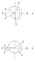
図2は、排気側可変動弁機構19と吸気側可変動弁機構18とによって実現されるバルブタイミングの特性を示している。 FIG. 2 shows valve timing characteristics realized by the exhaust-side
図2の(a)の制御状態においては、180°CAを越える作動角を有する排気弁5の開閉時期が排気側可変動弁機構19によって相対的に遅角側に制御されており、排気弁閉時期(EVC)が上死点(TDC)後にあり、排気弁開時期(EVO)は下死点(BDC)よりも多少進角側にある。吸気弁4の作動角は、例えば180°CAを越える比較的大きなものとなっており、吸気側可変動弁機構18によって相対的に進角側に制御されている。これにより、吸気弁開時期(IVO)が上死点(TDC)よりも僅かに進角側にあり、吸気弁閉時期(IVC)が下死点(BDC)よりも遅角側にある。以下では、この図2(a)のようなバルブタイミングを、排気弁5および吸気弁4の双方の特性を含めて、「第1のバルブタイミング」と呼ぶ。この第1のバルブタイミングでは、排気弁閉時期と吸気弁開時期とがいわゆるポジティブオーバラップの関係にある。一例では、排気弁閉時期が上死点後(ATDC)5°CA、吸気弁開時期が上死点前(BTDC)17°CAであり、従って、オーバラップ量が+22°CAである。 In the control state shown in FIG. 2(a), the opening/closing timing of the
図2(b)の制御状態においては、排気弁5のバルブタイミングが相対的に進角側に制御されており、排気弁閉時期(EVC)が上死点(TDC)前にあり、排気弁開時期(EVO)は下死点(BDC)よりも大きく進角した位置にある。吸気弁4のバルブタイミングは、相対的に遅角側に制御されており、吸気弁開時期(IVO)が上死点(TDC)よりも遅角側に位置し、吸気弁閉時期(IVC)が下死点(BDC)よりも大きく遅角した位置にある。以下では、この図2の(b)のようなバルブタイミングを、便宜上、吸気弁4側の特性をも含めて、「第2のバルブタイミング」と呼ぶ。この第2のバルブタイミングでは、排気弁閉時期と吸気弁開時期とが重ならないいわゆるネガティブオーバラップの関係にある。一例では、排気弁閉時期が上死点前(BTDC)25°CA、吸気弁開時期が上死点後(ATDC)25°CAであり、従って、オーバラップ量が-50°CAである。 In the control state of FIG. 2(b), the valve timing of the
内燃機関1の始動後、触媒23の暖機が完了するまでは、触媒23の暖機促進のために、触媒暖機運転がなされる。この触媒暖機運転においては、燃焼重心が触媒暖機完了後の通常燃焼運転中の燃焼重心よりも遅角側となるように点火時期を遅らせたリタード燃焼が行われる。 After the start of the
そして、触媒未暖機の状態において、車両停止中のアイドル運転に代表される低負荷側の第1の運転領域では、バルブタイミングとして、ポジティブオーバラップである第1のバルブタイミングが選択される。 Then, in a state where the catalyst is not yet warmed up, the positive overlap first valve timing is selected as the valve timing in the first operating region on the low load side typified by idling while the vehicle is stopped.
他方、触媒23が未暖機であるにも拘わらず車両を発進・加速した状況に代表される高負荷側の第2の運転領域では、バルブタイミングとして、排気弁閉時期(EVC)が上死点前となる第2のバルブタイミングが選択される。 On the other hand, in the second operating region on the high load side, which is represented by the situation where the vehicle is started and accelerated while the
HCの排出特性は、排気弁5が開いた瞬間の一次ピークのほかに、前述したように、シリンダ壁面に付着した液膜に起因する未燃HCが排気弁5を通して排気弁5の閉時期直前に押し出されてしまう、いわゆる二次ピークが存在する。上記実施例では、上記のようにバルブタイミングを選択することで、それぞれの状況下で、二次ピークとなるHCを適切に抑制できる。 In addition to the primary peak at the moment the
図3は、適当な一定の機関回転速度(例えば2000rpm)の下で、第1のバルブタイミングで運転した場合と第2のバルブタイミングで運転した場合の負荷(図示平均有効圧:IMEP)とHCとの関係を示している。図示するように、ある負荷Sまでは、第2のバルブタイミングよりも第1のバルブタイミングの方がHCの排出が少ない。そして、ある負荷Sを越えると、両者の関係が逆転し、第1のバルブタイミングよりも第2のバルブタイミングの方がHCの排出が少なくなる。従って、負荷Sよりも低負荷側の第1の運転領域で第1のバルブタイミングを選択し、負荷Sを越えた高負荷側の第2の運転領域で第2のバルブタイミングを選択することで、HCの排出が効果的に抑制される。 FIG. 3 shows the load (indicated mean effective pressure: IMEP) and HC when operated at the first valve timing and at the second valve timing under an appropriate constant engine speed (for example, 2000 rpm). It shows the relationship with As shown, up to a certain load S, less HC is emitted with the first valve timing than with the second valve timing. Then, when a certain load S is exceeded, the relationship between the two is reversed, and HC emissions become smaller with the second valve timing than with the first valve timing. Therefore, by selecting the first valve timing in the first operating region on the lower load side than the load S and selecting the second valve timing in the second operating region on the higher load side exceeding the load S, , HC emissions are effectively suppressed.
ここで両者の境界となる負荷Sは、後述するように、ターボ過給機12の存在を前提として、吸気圧が大気圧近傍となる負荷に相当し、換言すれば、第1のバルブタイミングの下で吸気弁開時期における筒内圧と吸気圧とがバランスすることとなる負荷に相当する。HCの排出特性の大小関係が逆転する負荷Sは、他の要素によっても多少変動し、従って、例えば機種毎にいわゆる適合により決定する必要がある。仮に、負荷Sの吸気圧が大気圧であるとすると、負荷Sよりも低負荷側では吸気圧が負圧となり、負荷Sよりも高負荷側では吸気圧が過給により正圧となる。 Here, the load S, which is the boundary between the two, corresponds to the load at which the intake pressure is close to the atmospheric pressure on the assumption that the
「第1の運転領域」および「第2の運転領域」としては、上記のように閾値となる負荷Sを境に低負荷側を「第1の運転領域」、高負荷側を「第2の運転領域」としてもよいが、負荷Sが変動要素を含むので、これに代えて、図3に付記するように、負荷S1よりも低負荷側を「第1の運転領域」として第1のバルブタイミングとし、負荷S2よりも高負荷側を「第2の運転領域」として第2のバルブタイミングとするようにしてもよい。負荷S1と負荷S2との間は、いずれのバルブタイミングであってもHCの排出に顕著な差異がない中間領域であり、従って、いずれか任意のバルブタイミングとしてもよく、あるいは、第1のバルブタイミングと第2のバルブタイミングとの切換のヒステリシス領域としてもよい。 As the "first operating region" and the "second operating region", the low load side is the "first operating region" and the high load side is the "second operating region" with respect to the threshold load S as described above. However, since the load S includes a variable element, instead of this, as shown in FIG. The second valve timing may be set as the "second operating region" on the higher load side than the load S2. Between load S1 and load S2 is an intermediate region where there is no significant difference in HC emissions for any valve timing, so any valve timing may be used, or the first valve It may be a hysteresis region for switching between the timing and the second valve timing.
図4は、二次ピークとなるHCに対する第1のバルブタイミングによる引き戻し作用の説明図である。特に、吸気圧が負圧であることを前提とした説明図である。図4(a)は、排気弁5が開いており、かつピストン2が下死点付近にある状態を示しており、ピストン2の冠面や燃焼室3の壁面に符号51で示す未燃燃料ないし未燃HCが付着している。この位置からピストン2が上昇していき、上死点に近付くと、図4(b)のように、未燃HC51が排気ポート21へ押し出されていく。図4(b)のタイミングは、バルブオーバラップ期間であり、吸気弁4が開き始めている。この吸気弁4の開弁に伴い、吸気負圧が燃焼室3内に作用する。図4(c)は、バルブオーバラップ期間の終期つまり排気弁5の閉時期直前を示しており、排気ポート21内の排気圧よりも吸気ポート8側の吸気圧や燃焼室3内の圧力が相対的に低いことで、排気ポート21内の未燃HC51の一部が燃焼室3内に引き戻され、さらに一部は、吸気ポート8内に入る。これらの未燃HC51は、後続の燃焼サイクルにおいて燃焼される。 FIG. 4 is an explanatory diagram of the pullback action by the first valve timing for HC, which becomes the secondary peak. In particular, it is an explanatory diagram assuming that the intake pressure is a negative pressure. FIG. 4(a) shows a state in which the
図6は、このような引き戻し作用によるHCの排出特性を模式的に示した特性図であり、HCの排出量は、二次ピークとして排気上死点近傍で上昇する。しかし、図中に斜線を施して示す部分は、上述した引き戻し作用を受け、実際には排気系へ流出しない。つまり、過給が行われていない第1の運転領域では、第1のバルブタイミングとすることで、吸気ポート8ないし燃焼室3内への引き戻し作用によるHCの低減が図れる。 FIG. 6 is a characteristic diagram schematically showing the HC discharge characteristics due to such a pullback action, and the HC discharge amount rises as a secondary peak near exhaust top dead center. However, the hatched portion in the figure receives the above-described pullback action and does not actually flow out to the exhaust system. That is, in the first operating region in which supercharging is not performed, HC can be reduced by the return action to the intake port 8 or the combustion chamber 3 by setting the first valve timing.
図5は、二次ピークとなるHCに対する第2のバルブタイミングによるトラップ作用の説明図である。この第2のバルブタイミングが選択される第2の運転領域では、過給により吸気圧が高くなっており、上述した引き戻し作用を得ることができない。第2のバルブタイミングでは、排気弁5を早期に閉じることで二次ピークのHCがトラップされる。図5(a)は、排気弁5が開いており、かつピストン2が下死点付近にある状態を示しており、ピストン2の冠面や燃焼室3の壁面に符号51で示す未燃燃料ないし未燃HCが付着している。この位置からピストン2が上昇していくと、未燃HC51がピストン2により掻き上げられていくが、上死点に近付く前に排気弁5が閉じられる。図5(b)は、排気弁閉時期を示しており、上死点前に排気弁5が閉じることで二次ピークのHCの排出が制限される。このように、過給により吸気圧が高くなっていて上述した引き戻し作用が得られない第2の運転領域では、二次ピークのHCを燃焼室3内にトラップすることで、HCの低減が図れる。 FIG. 5 is an explanatory diagram of the trapping action by the second valve timing for HC that becomes the secondary peak. In the second operating region where the second valve timing is selected, the intake pressure is high due to supercharging, and the pullback action described above cannot be obtained. At the second valve timing, the second peak of HC is trapped by closing the
図7は、過給が行われていない第1の運転領域での筒内圧と吸気圧との関係を示した特性図であり、特に第1のバルブタイミングの下での特性を示している。図示するように、下死点前の排気弁開時期(EVO)において排気弁5が開くことで、筒内圧が急激に低下していく。排気弁5が閉じる排気弁閉時期(EVC)は上死点後であるが、この排気弁閉時期よりも前の吸気弁開時期(IVO)において吸気弁4が開くため、筒内圧は、最終的に吸気圧まで低下する。ここで、図7では、吸気弁開時期において筒内圧は吸気圧よりも十分に高く、この両者の圧力差によって上述した引き戻し作用が得られる。なお、吸気弁開時期と排気弁閉時期との間がバルブオーバラップ期間である。 FIG. 7 is a characteristic diagram showing the relationship between the in-cylinder pressure and the intake pressure in the first operating region where supercharging is not performed, and particularly shows the characteristic under the first valve timing. As shown in the figure, the
これに対し、図8は、過給が行われている第2の運転領域での筒内圧と吸気圧との関係を示した特性図であり、特に第1のバルブタイミングとした場合の特性を示している。この場合も同様に排気弁開時期から筒内圧が急激に低下していき、最終的に吸気圧に近付くが、過給により吸気圧が高くなっていることにより、吸気弁開時期における筒内圧と吸気圧との差は非常に小さい。従って、第2の運転領域で仮に第1のバルブタイミングとすると、上述した引き戻し作用を得ることができず、二次ピークのHCがそのまま排出されてしまう。従って、上記実施例では、このように過給により吸気圧が高くなる条件下では、第2のバルブタイミングとして排気弁5を早期に閉じることで、二次ピークのHCの排出を抑制するのである。 In contrast, FIG. 8 is a characteristic diagram showing the relationship between the in-cylinder pressure and the intake pressure in the second operating region where supercharging is performed. showing. In this case as well, the cylinder pressure drops sharply from the exhaust valve opening timing and finally approaches the intake pressure. The difference with the intake pressure is very small. Therefore, if the first valve timing is used in the second operating region, the above-described pullback action cannot be obtained, and the secondary peak HC is discharged as it is. Therefore, in the above-described embodiment, under the condition that the intake pressure increases due to supercharging, the
図9は、エンジンコントローラ10において実行される触媒暖機運転制御の処理の流れを示すフローチャートである。このフローチャートに示す処理は、内燃機関1の運転中、繰り返し実行される。ステップ1では、触媒23の暖機が完了しているか否か、つまり、触媒23の温度が所定の活性温度に到達しているか否か、を判定する。触媒23の暖機が完了していれば、ステップ2へ進み、通常の燃焼モードとする。この通常燃焼モードでは、特殊な状況を除き、燃費が最適となるように燃焼時期が制御されるとともに、バルブタイミングが第1のバルブタイミングとなる。第1,第2のバルブタイミングとは異なる燃費を重視した第3のバルブタイミングとしてもよい。 FIG. 9 is a flow chart showing the flow of catalyst warm-up control processing executed in the engine controller 10 . The processing shown in this flowchart is repeatedly executed while the
触媒23の暖機が未完了である場合は、ステップ3へ進み、吸気圧センサ17により検出された吸気圧(過給圧)が大気圧近傍にある所定の圧力閾値以上であるか否かを判定する。圧力閾値は、例えば、第1のバルブタイミングの下で吸気弁開時期における筒内圧と吸気圧とがバランスする圧力として予め設定されている。なお、「バランスする」とは両者が完全に一致する意味ではなく、図7,図8で説明したように、圧力差による引き戻し作用が得られない程度に両者の圧力差が小さい状態を意味している。勿論、吸気弁開時期における筒内圧と吸気圧とが完全に一致する点を圧力閾値としてもよい。圧力閾値は、例えば内燃機関1の機種毎に実験的に求めることができる。そして、圧力閾値は、内燃機関1の回転速度毎に設定することが望ましい。 If the warm-up of the
吸気圧が圧力閾値未満であれば、過給が行われていない第1の運転領域であるとみなして、ステップ4へ進んで第1のバルブタイミングを選択する。吸気圧が圧力閾値以上であれば、過給が行われている第2の運転領域であるとみなして、ステップ5へ進んで第2のバルブタイミングを選択する。このようなバルブタイミングの選択により、図4あるいは図5で説明したようなそれぞれの条件に適した二次ピークの未燃HCの排出抑制がなされる。 If the intake pressure is less than the pressure threshold, it is considered to be in the first operating region where supercharging is not performed, and the process proceeds to step 4 to select the first valve timing. If the intake pressure is equal to or higher than the pressure threshold, it is regarded as the second operating region in which supercharging is performed, and the process proceeds to step 5 to select the second valve timing. By selecting the valve timing in this way, the emission of unburned HC at the secondary peak suitable for each condition as described with reference to FIG. 4 or 5 is suppressed.
そして、いずれの場合もステップ6へ進み、燃焼重心を比較的大きく遅角させたリタード燃焼を実行する。このように燃焼重心を遅角させることで、排気温度が高く得られ、触媒23の昇温が促進されるとともに、高い排気温度によりいわゆる後燃えが生じ、未燃HCの排出が低減する。 In either case, the process proceeds to step 6 to execute retarded combustion in which the combustion center of gravity is retarded relatively greatly. By retarding the center of gravity of combustion in this way, the exhaust gas temperature can be increased, and the temperature rise of the
前述したように、車両停止中のアイドル状態であれば、吸気圧は圧力閾値よりも低く、従って、ステップ4へ進んで第1のバルブタイミングとなる。車両の発進加速時には、吸気圧は圧力閾値よりも高く、従って、ステップ5へ進んで第2のバルブタイミングとなる。 As described above, if the vehicle is in an idling state while the vehicle is stopped, the intake pressure is lower than the pressure threshold, so the process proceeds to step 4 and the first valve timing is set. During vehicle start acceleration, the intake pressure is higher than the pressure threshold, so the process proceeds to step 5 for the second valve timing.
従って、ステップ3の圧力閾値に基づく判定に代えて、車両停止中のアイドル状態であるか否かの判定を行い、第1のバルブタイミングもしくは第2のバルブタイミングの選択を行うようにしてもよい。 Therefore, instead of the determination based on the pressure threshold in step 3, it is possible to determine whether the vehicle is in an idling state while the vehicle is stopped, and select the first valve timing or the second valve timing. .
あるいは、ステップ3の吸気圧の判定に代えて内燃機関1の要求負荷を負荷閾値と比較するようにしてもよい。負荷閾値は回転速度毎に設定することが望ましい。つまり、車両停止中のアイドル時には第1のバルブタイミングとし、車両の発進加速が行われ、要求負荷が機関回転速度毎に予め設定された所定の負荷閾値以上となったら第2のバルブタイミングに切り換えるようにすることができる。 Alternatively, instead of determining the intake pressure in step 3, the required load of the
以上、この発明の一実施例を説明したが、この発明は上記実施例にのみ限定されるものではなく、種々の変更が可能である。例えば、上記実施例では、吸気弁4も可変動弁機構を備えているが、吸気弁4のバルブタイミングが固定のものであってもよい。また、排気弁5の可変動弁機構としては、カムシャフトの位相を変化させる可変バルブタイミング機構に限らず、他の形式の機構であってもよい。 Although one embodiment of the present invention has been described above, the present invention is not limited to the above embodiment, and various modifications are possible. For example, in the above embodiment, the intake valve 4 also has a variable valve mechanism, but the valve timing of the intake valve 4 may be fixed. Further, the variable valve mechanism of the
また、必ずしも第2のバルブタイミングでネガティブオーバラップとなる必要はない。また、第2のバルブタイミングにおける吸気弁開時期は上死点後に限られず、上死点前であってもよい。さらに、触媒の暖機完了は、触媒温度センサ25を用いずに他の手段ないし方法によって判定するようにしてもよい。 Also, it is not always necessary to have a negative overlap at the second valve timing. Further, the intake valve opening timing in the second valve timing is not limited to after top dead center, and may be before top dead center. Further, the completion of warm-up of the catalyst may be determined by other means or methods without using the
過給機としては、実施例のターボ過給機12に限られず、機械式過給機であってもよい。 The supercharger is not limited to the
Claims (6)
触媒が未暖機の触媒暖機運転中に、
過給が行われないアイドル運転を含む低負荷側の第1の運転領域では第1のバルブタイミングとし、
過給が行われる車両の発進加速状況を含む高負荷側の第2の運転領域では第2のバルブタイミングとし、
車両停止中のアイドル時に第1のバルブタイミングに制御されている状態から、車両の発進加速が行われ、吸気圧が大気圧近傍の所定の圧力閾値以上となるか、または、要求負荷が機関回転速度毎に予め設定された所定の負荷閾値以上となったら、第2のバルブタイミングに切り換える、
車両用内燃機関の制御方法。 A first valve timing that has a variable valve mechanism on at least the exhaust valve side, the exhaust valve closing timing is later than the top dead center and positively overlaps the intake valve opening timing, and the exhaust valve closing timing is higher. A control method for a vehicle internal combustion engine equipped with a supercharger capable of controlling a second valve timing earlier than dead center, comprising:
During catalyst warm-up operation when the catalyst is not yet warmed up,
The first valve timing is set in the first operating region on the low load side including idle operation in which supercharging is not performed,
The second valve timing is set in the second operating region on the high load side including the starting acceleration of the vehicle in which supercharging is performed,
When the vehicle is idling while the vehicle is stopped , the vehicle is started and accelerated from the state controlled to the first valve timing, and the intake pressure becomes equal to or higher than a predetermined pressure threshold near the atmospheric pressure, or the required load reaches the engine. Switching to the second valve timing when the load exceeds a predetermined load threshold preset for each rotational speed;
A control method for a vehicle internal combustion engine.
請求項1に記載の車両用内燃機関の制御方法。 The pressure threshold is set in advance as a pressure at which the in-cylinder pressure and the intake pressure are balanced at the intake valve opening timing under the first valve timing.
A control method for an internal combustion engine for a vehicle according to claim 1 .
請求項1または2に記載の車両用内燃機関の制御方法。 Negative overlap occurs at the second valve timing with respect to the intake valve opening timing that is fixed or variably controlled,
3. The control method for a vehicle internal combustion engine according to claim 1 or 2 .
請求項1~3のいずれかに記載の車両用内燃機関の制御方法。 During catalyst warm-up operation, retarded combustion is performed.
A control method for a vehicle internal combustion engine according to any one of claims 1 to 3 .
請求項1~4のいずれかに記載の車両用内燃機関の制御方法。 The exhaust valve closing timing at the second valve timing is 25°CA before top dead center or on the advance side.
A control method for a vehicle internal combustion engine according to any one of claims 1 to 4 .
排気弁と、
排気系に設けられた触媒と、
少なくとも排気弁側に設けられた可変動弁機構を含み、排気弁閉時期が上死点よりも遅くかつ吸気弁開時期に対してポジティブオーバラップとなる第1のバルブタイミングと、排気弁閉時期が上死点よりも早い第2のバルブタイミングと、を実現可能な動弁装置と、
過給機と、
を備えた車両用内燃機関の制御装置であって、
触媒が未暖機の触媒暖機運転中に、上記動弁装置を、
過給が行われないアイドル運転を含む低負荷側の第1の運転領域では第1のバルブタイミングとし、
過給が行われる車両の発進加速状況を含む高負荷側の第2の運転領域では第2のバルブタイミングとし、
車両停止中のアイドル時に第1のバルブタイミングに制御されている状態から、車両の発進加速が行われ、吸気圧が大気圧近傍の所定の圧力閾値以上となるか、または、要求負荷が機関回転速度毎に予め設定された所定の負荷閾値以上となったら、第2のバルブタイミングに切り換える、
車両用内燃機関の制御装置。 an intake valve;
an exhaust valve;
a catalyst provided in the exhaust system;
A first valve timing including a variable valve mechanism provided at least on the exhaust valve side, wherein the exhaust valve closing timing is later than the top dead center and positively overlaps the intake valve opening timing, and the exhaust valve closing timing. a second valve timing that is earlier than top dead center;
a turbocharger;
A control device for a vehicle internal combustion engine comprising
During catalyst warm-up operation when the catalyst is not yet warmed up, the valve gear is
The first valve timing is set in the first operating region on the low load side including idle operation in which supercharging is not performed,
The second valve timing is set in the second operating region on the high load side including the starting acceleration situation of the vehicle in which supercharging is performed,
When the vehicle is idling while the vehicle is stopped , the vehicle is started and accelerated from the state controlled to the first valve timing, and the intake pressure becomes equal to or higher than a predetermined pressure threshold near the atmospheric pressure, or the required load reaches the engine. Switching to the second valve timing when the load exceeds a predetermined load threshold preset for each rotational speed;
A control device for a vehicle internal combustion engine.
Applications Claiming Priority (1)
| Application Number | Priority Date | Filing Date | Title |
|---|---|---|---|
| PCT/IB2020/000096 WO2021165711A1 (en) | 2020-02-20 | 2020-02-20 | Internal combustion engine control method and internal combustion engine control device |
Publications (3)
| Publication Number | Publication Date |
|---|---|
| JPWO2021165711A1 JPWO2021165711A1 (en) | 2021-08-26 |
| JPWO2021165711A5 JPWO2021165711A5 (en) | 2022-08-26 |
| JP7276589B2 true JP7276589B2 (en) | 2023-05-18 |
Family
ID=77390476
Family Applications (1)
| Application Number | Title | Priority Date | Filing Date |
|---|---|---|---|
| JP2022501378A Active JP7276589B2 (en) | 2020-02-20 | 2020-02-20 | CONTROL METHOD AND CONTROL DEVICE FOR INTERNAL COMBUSTION ENGINE |
Country Status (2)
| Country | Link |
|---|---|
| JP (1) | JP7276589B2 (en) |
| WO (1) | WO2021165711A1 (en) |
Citations (7)
| Publication number | Priority date | Publication date | Assignee | Title |
|---|---|---|---|---|
| JP2001159363A (en) | 1999-09-24 | 2001-06-12 | Toyota Motor Corp | Exhaust emission control device for internal combustion engine |
| JP2005188486A (en) | 2003-12-26 | 2005-07-14 | Mitsubishi Motors Corp | Control device of engine with motor-driven supercharger |
| JP2006322335A (en) | 2005-05-17 | 2006-11-30 | Toyota Motor Corp | Control system of internal combustion engine |
| JP2007332938A (en) | 2006-06-19 | 2007-12-27 | Toyota Motor Corp | Controller of internal combustion engine |
| WO2017126277A1 (en) | 2016-01-22 | 2017-07-27 | 日産自動車株式会社 | Waste gate valve control method and control device |
| JP2017172565A (en) | 2016-03-25 | 2017-09-28 | いすゞ自動車株式会社 | Engine warming-up device |
| JP2018168795A (en) | 2017-03-30 | 2018-11-01 | マツダ株式会社 | Control device for compression self-ignition type engine |
-
2020
- 2020-02-20 WO PCT/IB2020/000096 patent/WO2021165711A1/en active Application Filing
- 2020-02-20 JP JP2022501378A patent/JP7276589B2/en active Active
Patent Citations (7)
| Publication number | Priority date | Publication date | Assignee | Title |
|---|---|---|---|---|
| JP2001159363A (en) | 1999-09-24 | 2001-06-12 | Toyota Motor Corp | Exhaust emission control device for internal combustion engine |
| JP2005188486A (en) | 2003-12-26 | 2005-07-14 | Mitsubishi Motors Corp | Control device of engine with motor-driven supercharger |
| JP2006322335A (en) | 2005-05-17 | 2006-11-30 | Toyota Motor Corp | Control system of internal combustion engine |
| JP2007332938A (en) | 2006-06-19 | 2007-12-27 | Toyota Motor Corp | Controller of internal combustion engine |
| WO2017126277A1 (en) | 2016-01-22 | 2017-07-27 | 日産自動車株式会社 | Waste gate valve control method and control device |
| JP2017172565A (en) | 2016-03-25 | 2017-09-28 | いすゞ自動車株式会社 | Engine warming-up device |
| JP2018168795A (en) | 2017-03-30 | 2018-11-01 | マツダ株式会社 | Control device for compression self-ignition type engine |
Also Published As
| Publication number | Publication date |
|---|---|
| WO2021165711A1 (en) | 2021-08-26 |
| JPWO2021165711A1 (en) | 2021-08-26 |
Similar Documents
| Publication | Publication Date | Title |
|---|---|---|
| JP4816812B2 (en) | Control device for internal combustion engine | |
| US8978378B2 (en) | Method and system for reducing turbocharger noise during cold start | |
| US8109092B2 (en) | Methods and systems for engine control | |
| US8272207B2 (en) | Late post injection of fuel for particulate filter heating | |
| US20080065310A1 (en) | Manifold pressure control for a variable event valvetrain | |
| US20100300383A1 (en) | Methods and Systems for Engine Control | |
| US10718275B2 (en) | Miller cycle engine | |
| JP3525737B2 (en) | In-cylinder injection gasoline engine | |
| JP2004124754A (en) | Engine starter | |
| JP2000073803A (en) | Cylinder injection gasoline engine | |
| US10641186B2 (en) | Internal combustion engine control apparatus | |
| JP2009074366A (en) | Variable valve gear of internal combustion engine | |
| JP3771101B2 (en) | Control device for internal combustion engine | |
| JP7276589B2 (en) | CONTROL METHOD AND CONTROL DEVICE FOR INTERNAL COMBUSTION ENGINE | |
| JP5851463B2 (en) | Valve timing control device for internal combustion engine | |
| JP3812138B2 (en) | Control device for turbocharged engine | |
| RU2633298C2 (en) | Operation method of turbocharger (versions) | |
| JP5593132B2 (en) | Control device for internal combustion engine | |
| JP7359221B2 (en) | Catalyst warm-up operation control method and catalyst warm-up operation control device for vehicle internal combustion engine | |
| CN112112737A (en) | Method and system for controlling stop of engine | |
| JP7256682B2 (en) | Internal combustion engine control method and internal combustion engine control device | |
| JP7155962B2 (en) | engine controller | |
| WO2022064237A1 (en) | Control method and control device for internal combustion engine | |
| JP6493508B1 (en) | Engine start control device | |
| JP2021165548A (en) | Deceleration control method and deceleration control device of internal combustion engine with turbocharger |
Legal Events
| Date | Code | Title | Description |
|---|---|---|---|
| A521 | Request for written amendment filed |
Free format text: JAPANESE INTERMEDIATE CODE: A523 Effective date: 20220512 |
|
| A621 | Written request for application examination |
Free format text: JAPANESE INTERMEDIATE CODE: A621 Effective date: 20220512 |
|
| A131 | Notification of reasons for refusal |
Free format text: JAPANESE INTERMEDIATE CODE: A131 Effective date: 20230207 |
|
| A521 | Request for written amendment filed |
Free format text: JAPANESE INTERMEDIATE CODE: A523 Effective date: 20230303 |
|
| TRDD | Decision of grant or rejection written | ||
| A01 | Written decision to grant a patent or to grant a registration (utility model) |
Free format text: JAPANESE INTERMEDIATE CODE: A01 Effective date: 20230404 |
|
| A61 | First payment of annual fees (during grant procedure) |
Free format text: JAPANESE INTERMEDIATE CODE: A61 Effective date: 20230417 |
|
| R151 | Written notification of patent or utility model registration |
Ref document number: 7276589 Country of ref document: JP Free format text: JAPANESE INTERMEDIATE CODE: R151 |