JP3989231B2 - Synthetic resin box-shaped product and manufacturing method thereof - Google Patents
Synthetic resin box-shaped product and manufacturing method thereof Download PDFInfo
- Publication number
- JP3989231B2 JP3989231B2 JP2001352692A JP2001352692A JP3989231B2 JP 3989231 B2 JP3989231 B2 JP 3989231B2 JP 2001352692 A JP2001352692 A JP 2001352692A JP 2001352692 A JP2001352692 A JP 2001352692A JP 3989231 B2 JP3989231 B2 JP 3989231B2
- Authority
- JP
- Japan
- Prior art keywords
- synthetic resin
- box
- resin material
- skin material
- molding
- Prior art date
- Legal status (The legal status is an assumption and is not a legal conclusion. Google has not performed a legal analysis and makes no representation as to the accuracy of the status listed.)
- Expired - Fee Related
Links
- 229920003002 synthetic resin Polymers 0.000 title claims description 88
- 239000000057 synthetic resin Substances 0.000 title claims description 88
- 238000004519 manufacturing process Methods 0.000 title claims description 12
- 239000000463 material Substances 0.000 claims description 163
- 238000000465 moulding Methods 0.000 claims description 58
- 230000002093 peripheral effect Effects 0.000 claims description 17
- 238000005470 impregnation Methods 0.000 claims description 6
- 238000000034 method Methods 0.000 description 8
- 238000002347 injection Methods 0.000 description 7
- 239000007924 injection Substances 0.000 description 7
- 238000001746 injection moulding Methods 0.000 description 6
- 230000008569 process Effects 0.000 description 6
- 230000037303 wrinkles Effects 0.000 description 5
- 239000004744 fabric Substances 0.000 description 4
- 239000004745 nonwoven fabric Substances 0.000 description 4
- 239000002759 woven fabric Substances 0.000 description 4
- 239000004952 Polyamide Substances 0.000 description 2
- 238000010586 diagram Methods 0.000 description 2
- 230000000694 effects Effects 0.000 description 2
- 230000006872 improvement Effects 0.000 description 2
- 229920002647 polyamide Polymers 0.000 description 2
- 229920000098 polyolefin Polymers 0.000 description 2
- 238000003825 pressing Methods 0.000 description 2
- 230000003014 reinforcing effect Effects 0.000 description 2
- 239000002344 surface layer Substances 0.000 description 2
- 239000000853 adhesive Substances 0.000 description 1
- 230000001070 adhesive effect Effects 0.000 description 1
- 230000008859 change Effects 0.000 description 1
- 230000007423 decrease Effects 0.000 description 1
- 230000001771 impaired effect Effects 0.000 description 1
- 229920005989 resin Polymers 0.000 description 1
- 239000011347 resin Substances 0.000 description 1
- 239000012815 thermoplastic material Substances 0.000 description 1
- 229920005992 thermoplastic resin Polymers 0.000 description 1
- 230000007704 transition Effects 0.000 description 1
- 238000009966 trimming Methods 0.000 description 1
Images


Landscapes
- Containers Having Bodies Formed In One Piece (AREA)
- Laminated Bodies (AREA)
- Moulds For Moulding Plastics Or The Like (AREA)
- Injection Moulding Of Plastics Or The Like (AREA)
Description
【0001】
【発明の属する技術分野】
本発明は合成樹脂製の箱型形状品に係り、特に、内側に表皮材を固着した箱型形状品の改良に関するものである。
【0002】
【従来の技術】
底部と、その底部の全周に設けられた側壁部とを有して、合成樹脂材料にて一体成形された箱型形状品が知られている。例えば、底部が四角形状を成しているとともに側壁部の開口側端部に外側へ突き出す外向きフランジが一体に設けられた箱型容器が、各種の部品の製造工程や組付工程などで部品を収納したり搬送したりするために用いられている。そして、このような箱型容器の一種に、部品投入時等の衝突音の緩和や意匠性向上などを目的として、底部および側壁部の内側面に織布や不織布、編布などの表皮材を一体的に固着することが考えられている。
【0003】
【発明が解決しようとする課題】
しかしながら、このように箱型形状品の内側に表皮材を固着する場合、接着剤を使用して貼り付ける場合には製造工数が増えてコスト高になる一方、合成樹脂材料の成形と同時に表皮材を成形するとともに、その合成樹脂材料の含浸によって表皮材を一体的に固着する場合には、側壁部の開口側端面で表皮材に皺が寄ったり、合成樹脂材料が表皮材を通過して表面に滲み出したりして、外観品質が損なわれることがあった。すなわち、表皮材を一体成形する場合には、皺が寄らないように表皮材を外周側へ引っ張りながら一対の成形型を型締めするが、合成樹脂材料が含浸可能な織布や不織布、編布などの表皮材は伸び変形量が小さいため、例えば側壁部の角部の開口側端面で皺が寄ることが避けられないとともに、表皮材の外周部を強く固定すると、図5に示すように表皮材18に所定の張力を付与した状態で一対の成形型32、34を型締めした後、図6に示すように合成樹脂材料16を射出成形する際に、側壁部14の上端部で表皮材18が成形面40に密着せず、合成樹脂材料16が表皮材18を通過して部分的に表面に滲み出すことがあるのである。
【0004】
本発明は以上の事情を背景として為されたもので、その目的とするところは、箱型形状品を合成樹脂材料にて一体成形すると同時に表皮材を成形して内側面に一体的に固着する場合に、側壁部の開口側端面の外観品質を向上させることにある。
【0005】
【課題を解決するための手段】
かかる目的を達成するために、第1発明は、底部と、その底部の全周に設けられた側壁部とを有して、合成樹脂材料にて一体成形された箱型形状品であって、(a) 前記合成樹脂材料が含浸可能な表皮材がその合成樹脂材料の前記一体成形と同時に成形され、且つその合成樹脂材料の含浸により前記底部および前記側壁部の内側面に一体的に固着されているとともに、(b) 前記側壁部の開口側の端面には、前記合成樹脂材料が前記表皮材を通過して突き出す突起が全周に設けられていることを特徴とする。
【0006】
第2発明は、第1発明の合成樹脂製箱型形状品において、前記突起は、少なくとも前記側壁部の開口側の端面における内周側部分に、その側壁部の内側面に連続して突き出すように設けられていることを特徴とする。
第3発明は、第1発明または第2発明の合成樹脂製箱型形状品において、(a) 前記箱型形状品は、前記底部が四角形状を成しているとともに前記側壁部の開口側端部に外側へ突き出す外向きフランジが一体に設けられた箱型容器で、(b) 前記突起は、前記外向きフランジの全周に連続して設けられた環状突起であることを特徴とする。
【0007】
第4発明は、第1発明〜第3発明の何れかの合成樹脂製箱型形状品の製造方法であって、(a) 前記箱型形状品の外側形状に対応する第1成形面を有する第1成形型と、該箱型形状品の前記表皮材が固着された内側形状に対応する第2成形面を有するとともにその第2成形面の外周側に前記突起に対応する凹所が設けられた第2成形型との間に、前記表皮材を介在させるとともにその表皮材が内側へ流入することを制限した状態で、その第1成形型および第2成形型を型締めする型締め工程と、(b) 前記第1成形型の第1成形面と前記表皮材との間に前記合成樹脂材料を射出して、その表皮材を前記第2成形型の第2成形面に密着させながらその合成樹脂材料を一体成形し、且つ、その合成樹脂材料の含浸によりその表皮材を合成樹脂材料に一体的に固着するとともに、前記側壁部の開口側の端面では、内側への流入が制限された前記表皮材をその合成樹脂材料が通過して前記凹所内に侵入することにより前記突起が一体成形される成形工程と、を有することを特徴とする。
【0008】
【発明の効果】
第1発明の合成樹脂製箱型形状品によれば、表皮材が合成樹脂材料の一体成形と同時に成形され、且つその合成樹脂材料の含浸により一体的に固着されているため、内側面に表皮材が固着された箱型形状品が安価に製造される。しかも、側壁部の開口側の端面には、合成樹脂材料が表皮材を通過して突き出す突起が全周に設けられているため、合成樹脂材料が部分的に表面に滲み出している場合に比較して外観品質が向上するとともに、側壁部の開口側端面における表皮材の皺や合成樹脂材料の部分的な滲出を考慮する必要がないため、箱型形状品の形状設計の自由度が向上する。すなわち、本発明では合成樹脂材料が部分的に表皮材から滲み出すのではなく、積極的に表皮材に浸透させて通過させることにより、その合成樹脂材料のみから成る突起を側壁部の開口側端面に設けることにより、外観品質を向上させるようにしたのである。
【0009】
第3発明は、部品などを収納したり搬送したりするための箱型容器で、内側に表皮材が設けられることにより意匠性が向上するとともに部品投入時の衝撃が緩和される。また、側壁部上端の外向きフランジの全周に連続して環状突起が設けられているため、環状突起が補強リブとして機能し、外向きフランジの強度が向上して変形や破損が防止される。
【0010】
第4発明は、上記合成樹脂製箱型形状品の製造方法に関するもので、実質的に第1発明〜第3発明と同様の効果が得られる。加えて、一対の第1成形型および第2成形型の間に表皮材を介在させた状態で型締めし、第1成形型の第1成形面と表皮材との間に合成樹脂材料を射出するだけで、合成樹脂材料の成形と同時に表皮材が成形され且つ一体的に固着されるとともに、側壁部の開口側の端面では合成樹脂材料が表皮材を通過して前記突起が一体成形されるため、第1発明〜第3発明の合成樹脂製箱型形状品を簡単且つ安価に製造することができる。すなわち、合成樹脂材料が供給される側と反対の第2成形型に凹所が設けられているため、内側への流入が制限されている表皮材に対して合成樹脂材料が所定の射出圧で押圧されることにより、その表皮材に合成樹脂材料が浸透して反対側の凹所内に侵入し、凹所に対応する突起が一体成形されるのである。
【0011】
【発明の実施の形態】
本発明は、部品製造工程や組付工程などで部品を収容したり搬送したりする四角形(一般に長方形や正方形)の箱型容器に好適に適用されるが、室内に配置される本棚や飾り棚、家具などの他の箱型形状品にも適用できる。側壁部は、例えば底部に対して略垂直に立ち上がるように設けられるが、開口側程外側へ開くように傾斜して設けることもできる。
【0012】
箱型形状品の基材となる合成樹脂材料は、要求強度などに応じて適宜定められるが、例えば第3発明の箱型容器の場合、所定の強度を有するポリオレフィン系やポリアミド系などの熱可塑性樹脂材料が好適に用いられる。合成樹脂材料が含浸可能な表皮材としては、織布や不織布、編布などが好適に用いられる。
【0013】
第3発明では底部が四角形状を成しているが、第1発明の実施に際しては三角形や5角形などの他の角形状であっても良いし、円や楕円形状など種々の形状を採用できる。また、第3発明の外向きフランジは必ずしも必須ではなく、側壁部が開口側端部まで一定の板厚で設けられ、その端面に突起を設ける場合であっても良い。
【0014】
第3発明の環状突起は、例えば外向きフランジの上面に内外周側へ離間して複数設けられるが、単一の環状突起を設けるだけでも良い。第1発明の実施に際しては、環状突起を設ける代わりに周方向と直角な長手状突起を周方向に所定の間隔で多数設けたり、周方向に対して傾斜する姿勢で多数の長手状突起を設けたり、円柱形状や角柱形状の多数の突起を設けたりするなど、種々の態様を採用できる。これらの突起は、先端側程幅寸法(或いは径寸法)が小さくなるように断面を台形としたり、截頭円錐形状としたりすることが望ましい。
【0015】
第4発明では、例えば絞り加工におけるしわ押えのようにスプリング等の付勢手段によって表皮材の外周縁部が把持されることにより、内側への流入が制限されるようにしたり、一対の第1成形型および第2成形型が型締めされることにより、表皮材の外周縁部がそれ等の第1成形型および第2成形型により挟圧されて、内側への流入が阻止されるようにしたりするなど、種々の態様を採用できる。
【0016】
第4発明の製造方法はあくまでも一例であり、第1発明〜第3発明の箱型形状品の製造に際しては、例えば予め第1成形型の第1成形面上に溶融した合成樹脂材料を供給した後、第2成形型を接近させてプレス成形すると同時に、凹所部分では合成樹脂材料が表皮材を通過して突起が形成されるようにしたり、必要に応じて凹所側にも合成樹脂材料を供給したりするなど、種々の成形手法を採用できる。
【0017】
【実施例】
以下、本発明の実施例を図面を参照しつつ詳細に説明する。
図1は、本発明の合成樹脂製箱型形状品の一実施例である箱型容器10を示す図で、(a) は斜め上方から見た斜視図、(b) は(a) におけるB−B断面図である。この箱型容器10は、長方形の底部12と、その底部12の全周に設けられた略平板状の側壁部14とを有し、合成樹脂材料16にて一体成形されているとともに、それ等の底部12および側壁部14の内側面には所定のクッション性能を有する表皮材18が一体的に固着されている。合成樹脂材料16としては、所定の要求強度を有するポリオレフィン系やポリアミド系などの熱可塑性樹脂が用いられている一方、表皮材18としては合成樹脂材料16が含浸可能な織布や不織布、編布などが用いられており、その表皮材18は合成樹脂材料16の一体成形と同時に成形され、且つ、その合成樹脂材料16が表皮材18の裏面の表層部に含浸することにより一体的に固着されている。
【0018】
側壁部14は、底部12に対して略直角、厳密には僅かに外側へ傾斜する姿勢で設けられているとともに、その開口側端部である上端部には、外側へ突き出す外向きフランジ20が一体に設けられている。外向きフランジ20の上面には、前記合成樹脂材料16が表皮材18を通過して上方へ突き出すように、外向きフランジ20の全周に連続する環状突起22が設けられている。環状突起22は、内外周側へ離間して複数(本実施例では3本)設けられているとともに、各環状突起22は先端側程幅寸法が狭くなるように断面が台形形状を成している。
【0019】
図2は、上記箱型容器10を製造するための射出成形装置30を説明する部分断面図で、前記図1(b) の側壁部14を成形する部分を示す図であり、位置固定の第1成形型32、および第1成形型32に対して上下方向に接近離間させられる第2成形型34を備えている。第1成形型32は、箱型容器10の外側形状に対応する第1成形面36を有するとともに、その第1成形面36から前記合成樹脂材料16を所定の射出圧で射出する射出装置38が接続されている。第2成形型34は、箱型容器10の表皮材18が固着された内側形状に対応する第2成形面40を有するとともに、その第2成形面40の外周側には前記環状突起22に対応する凹所として3本の環状溝42が設けられている。
【0020】
また、上記第1成形型32および第2成形型34の周縁部には、表皮材18の外周部を把持して内側への流入を制限し、所定の張力を付与する把持装置44が設けられている。把持装置44は、第1成形型32に配設されるとともにスプリング等の付勢手段46によって上方へ付勢されている矩形環状の下側押圧型48と、第2成形型34に配設されるとともにスプリング等の付勢手段50によって下方へ付勢されている矩形環状の上側押圧型52とを備えており、第2成形型34の第2成形面40が表皮材18に接触して下方へ押し下げる際に、付勢手段46、50の付勢力で表皮材18の内側への流入が制限されて皺の発生が抑制される。なお、第2成形型34が下降端まで下降して型締めされた状態では、第1成形型32の外周突起54と第2成形型34の外周突起56との間で表皮材18が挟圧され、内側への流入が略阻止される。
【0021】
そして、このような射出成形装置30においては、先ず、図2に示すように第2成形型34が上昇して第1成形型32から離間させられた状態において、第1成形型32上に表皮材18を配置する。次に、図3に示すように第2成形型34を下降端まで下降させて型締めする。この時、第2成形型34の下降に伴って表皮材18は内側へ流入するが、把持装置44によって周縁部が把持されているため、表皮材18には所定の張力が付与され、底部12に対応する部分では表皮材18が第2成形型34の第2成形面40に略密着させられる。また、第2成形型34が下降端に達すると、第1成形型32の外周突起54と第2成形型34の外周突起56との間で表皮材18が挟圧され、それ以上の内側への流入が略阻止される。図2の型開き状態から図3の型締め状態への移行が型締め工程である。
【0022】
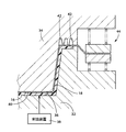
続いて、射出装置38により所定の射出圧で溶融した合成樹脂材料16を第1成形面36から射出すると、図4に示すように側壁部14に対応する部分も含めて表皮材18が第2成形面40に密着させられて成形されるとともに、その第2成形面40と第1成形面36との間で合成樹脂材料16が一体成形される。また、その合成樹脂材料16が表皮材18の裏面の表層部に含浸することにより、表皮材18が合成樹脂材料16に一体的に固着される。この時、表皮材18は内側への流入が略阻止されていることから、表皮材18は主として自身の伸び変形で第2成形面40に密着させられることになるが、側壁部14の上端部、すなわち環状溝42が設けられた部分では、合成樹脂材料16の射出圧により表皮材18が環状溝42内へ大きく侵入することはない。図4は、この状態であるが、環状溝42部分では溶融した合成樹脂材料16が射出圧により表皮材18に浸透して通過し、環状溝42内まで侵入して前記環状突起22が一体成形される。このように、溶融した合成樹脂材料16を射出して環状突起22が一体成形されるまでの工程が成形工程である。
【0023】
上記環状溝42の幅寸法や深さ、すなわち環状突起22の幅寸法wや高さ寸法t(図1(b) 参照)は、表皮材18の伸び変形で環状溝42内に表皮材18が大きくして侵入することがないように、例えばt≧1.5wを満足するように定められる。これにより、環状溝42に倣って表皮材18が変形し、環状突起22の側面や上面に部分的に表皮材18が露出する恐れがない。
【0024】
その後、合成樹脂材料16が冷却硬化した後、第2成形型34を上方へ離型して一体成形された箱型容器10を取り出すとともに、外向きフランジ20から外方へ延び出している余分な表皮材18をトリミングして除去することにより、図1に示す目的とする箱型容器10が得られる。
【0025】
このような本実施例の箱型容器10によれば、表皮材18が合成樹脂材料16の一体成形と同時に成形され、且つその合成樹脂材料16の含浸により一体的に固着されているため、内側面に表皮材18が固着された箱型容器10が安価に製造される。しかも、側壁部14の上端部に設けられた外向きフランジ20には、合成樹脂材料16が表皮材18を通過して突き出し、その合成樹脂材料16のみから成る環状突起22が設けられているため、図6に示すように合成樹脂材料16が部分的に表面に滲み出している場合に比較して外観品質が向上する。また、箱型容器10の形状設計に際して、外向きフランジ20部分の表皮材18の皺や合成樹脂材料16の部分的な滲出を考慮する必要がないため、設計の自由度が向上する。
【0026】
一方、このように箱型容器10の内側にクッション性を有する表皮材18が固着されることから、意匠性が向上するとともに部品投入時の衝撃が緩和される。また、側壁部14の上端の外向きフランジ20の全周に連続して複数の環状突起22が設けられているため、環状突起22が補強リブとして機能し、外向きフランジ20の強度が向上して変形や破損が防止される。
【0027】
また、本実施例では一対の第1成形型32および第2成形型34の間に表皮材18を介在させた状態で型締めし、第1成形型32の第1成形面36と表皮材18との間に合成樹脂材料16を射出するだけで、合成樹脂材料16の成形と同時に表皮材18が成形され且つ一体的に固着されるとともに、側壁部14の外向きフランジ20部分では合成樹脂材料16が表皮材18を通過して環状溝42内に侵入することにより環状突起22が一体成形されるため、箱型容器10を簡単且つ安価に製造することができる。
【0028】
以上、本発明の実施例を図面に基づいて詳細に説明したが、これはあくまでも一実施形態であり、本発明は当業者の知識に基づいて種々の変更,改良を加えた態様で実施することができる。
【図面の簡単な説明】
【図1】本発明の一実施例である箱型容器を示す図で、(a) は斜視図、(b) は(a) におけるB−B断面図である。
【図2】図1の箱型容器を製造するための射出成形装置を説明する部分断面図である。
【図3】図2の射出成形装置の一対の成形型を型締めした状態を示す図である。
【図4】図3の型締め状態で合成樹脂材料を射出して一体成形する工程で、環状溝内まで合成樹脂材料が達する前の状態を示す図である。
【図5】従来の箱型容器を射出成形によって製造する際の型締め状態を示す図である。
【図6】図5の型締め状態で合成樹脂材料を射出して一体成形する際に、側壁部の上端角部において合成樹脂材料が部分的に表皮材を通過して表面に滲み出した状態を示す図である。
【符号の説明】
10:箱型容器(箱型形状品) 12:底部 14:側壁部 16:合成樹脂材料 18:表皮材 20:外向きフランジ 22:環状突起(突起) 30:射出成形装置 32:第1成形型 34:第2成形型 36:第1成形面 40:第2成形面 42:環状溝(凹所)[0001]
BACKGROUND OF THE INVENTION
The present invention relates to a box-shaped product made of synthetic resin, and more particularly to an improvement of a box-shaped product having a skin material fixed inside.
[0002]
[Prior art]
A box-shaped product having a bottom part and a side wall part provided on the entire circumference of the bottom part and integrally formed of a synthetic resin material is known. For example, a box-shaped container with a bottom formed in a square shape and an outward flange projecting outwardly at the opening end of the side wall is an integral part of a manufacturing process or assembly process for various parts. Is used for storing and transporting. In addition, a skin material such as a woven fabric, a non-woven fabric, or a knitted fabric is applied to the inner surface of the bottom and side walls for the purpose of alleviating the impact sound and improving the design when a part is inserted. It is considered that they are fixed together.
[0003]
[Problems to be solved by the invention]
However, when the skin material is fixed inside the box-shaped product in this way, when using an adhesive, the manufacturing man-hour increases and the cost increases. On the other hand, the skin material simultaneously with the molding of the synthetic resin material When the skin material is integrally fixed by impregnating the synthetic resin material, the skin material is wrinkled at the opening side end surface of the side wall portion, or the synthetic resin material passes through the skin material and the surface. Occasionally, the appearance quality may be impaired. That is, when integrally forming the skin material, the pair of molds are clamped while pulling the skin material to the outer peripheral side so as not to wrinkle, but the woven fabric, nonwoven fabric, or knitted fabric that can be impregnated with the synthetic resin material For example, since the skin material such as the surface material has a small amount of elongation deformation, it is inevitable that wrinkles approach the end surface of the side wall at the opening side, and when the outer periphery of the skin material is strongly fixed, as shown in FIG. After the pair of molding dies 32 and 34 are clamped in a state where a predetermined tension is applied to the
[0004]
The present invention has been made against the background of the above circumstances, and the object of the present invention is to integrally mold a box-shaped product with a synthetic resin material, and at the same time mold a skin material to be integrally fixed to the inner surface. In this case, the appearance quality of the opening side end face of the side wall is to be improved.
[0005]
[Means for Solving the Problems]
In order to achieve such an object, the first invention is a box-shaped product having a bottom portion and a side wall portion provided on the entire circumference of the bottom portion, and integrally molded with a synthetic resin material, (a) A skin material that can be impregnated with the synthetic resin material is formed simultaneously with the integral molding of the synthetic resin material, and is integrally fixed to the inner surface of the bottom portion and the side wall portion by impregnation of the synthetic resin material. And (b) the end surface of the side wall portion on the opening side is provided with a protrusion provided on the entire periphery of the synthetic resin material that protrudes through the skin material.
[0006]
According to a second aspect of the present invention, in the synthetic resin box-shaped product according to the first aspect of the present invention, the protrusion protrudes continuously from an inner peripheral side portion of an end surface on the opening side of the side wall portion continuously to the inner side surface of the side wall portion. It is provided in.
A third invention is the box-shaped product made of synthetic resin according to the first or second invention, wherein (a) the box-shaped product has a square bottom and the opening side end of the side wall portion. (B) The protrusion is an annular protrusion provided continuously around the entire circumference of the outward flange.
[0007]
A fourth invention is a method for manufacturing a synthetic resin box-shaped product according to any one of the first to third inventions , and (a) has a first molding surface corresponding to the outer shape of the box-shaped product. The first molding die has a second molding surface corresponding to the inner shape to which the skin material of the box-shaped product is fixed, and a recess corresponding to the protrusion is provided on the outer peripheral side of the second molding surface. A mold clamping step of clamping the first mold and the second mold in a state where the skin material is interposed between the second mold and the skin material is restricted from flowing inward. (B) injecting the synthetic resin material between the first molding surface of the first mold and the skin material, and bringing the skin material into close contact with the second molding surface of the second mold; Synthetic resin material is integrally molded, and the skin material is integrated with synthetic resin material by impregnation with the synthetic resin material. At the end face of the side wall portion on the opening side, the projection is integrally formed by the synthetic resin material passing through the skin material whose inflow to the inside is restricted and entering the recess. And a molding step.
[0008]
【The invention's effect】
According to the synthetic resin box-shaped product of the first invention, the skin material is molded simultaneously with the integral molding of the synthetic resin material and is integrally fixed by impregnation of the synthetic resin material. A box-shaped product to which the material is fixed is manufactured at a low cost. In addition, the end surface on the opening side of the side wall portion is provided with protrusions that protrude through the outer surface of the synthetic resin material, so that the synthetic resin material partially oozes out to the surface. As a result, the appearance quality is improved and the degree of freedom in designing the shape of the box-shaped product is improved because there is no need to take into account wrinkles of the skin material or partial exudation of the synthetic resin material on the opening side end face of the side wall . That is, in the present invention, the synthetic resin material does not partially ooze out from the skin material, but actively penetrates and passes through the skin material, so that the projection made only of the synthetic resin material is the opening side end surface of the side wall portion. By providing it, the appearance quality is improved.
[0009]
The third invention is a box-type container for storing and transporting parts and the like. By providing a skin material on the inner side, the design is improved and the impact at the time of putting parts is reduced. In addition, since the annular protrusion is provided continuously around the entire circumference of the outward flange at the upper end of the side wall, the annular protrusion functions as a reinforcing rib, and the strength of the outward flange is improved and deformation and damage are prevented. .
[0010]
4th invention is related with the manufacturing method of the said synthetic-resin box-shaped goods, The effect similar to 1st invention -3rd invention is acquired substantially. In addition, the mold is clamped with a skin material interposed between the pair of first mold and second mold, and a synthetic resin material is injected between the first molding surface of the first mold and the skin material. As a result, the skin material is molded and fixed integrally at the same time as the molding of the synthetic resin material, and at the end surface on the opening side of the side wall portion, the synthetic resin material passes through the skin material and the projection is integrally molded. Therefore, the synthetic resin box-shaped product of the first to third inventions can be manufactured easily and inexpensively. That is, since the recess is provided in the second mold opposite to the side to which the synthetic resin material is supplied, the synthetic resin material is applied at a predetermined injection pressure to the skin material in which inflow to the inside is restricted. When pressed, the synthetic resin material penetrates into the skin material and enters into the recess on the opposite side, and the protrusion corresponding to the recess is integrally formed.
[0011]
DETAILED DESCRIPTION OF THE INVENTION
The present invention is preferably applied to a quadrangular (generally rectangular or square) box-shaped container that accommodates or conveys parts in a part manufacturing process, an assembly process, etc. It can also be applied to other box-shaped products such as furniture. For example, the side wall portion is provided so as to rise substantially vertically with respect to the bottom portion, but may be provided so as to be inclined outwardly toward the opening side.
[0012]
The synthetic resin material used as the base material for the box-shaped product is appropriately determined according to the required strength and the like. For example, in the case of the box-shaped container of the third invention, a thermoplastic material such as polyolefin or polyamide having a predetermined strength. A resin material is preferably used. As a skin material that can be impregnated with a synthetic resin material, a woven fabric, a nonwoven fabric, a knitted fabric, or the like is preferably used.
[0013]
In the third invention, the bottom has a quadrangular shape. However, in the practice of the first invention, other square shapes such as a triangle and a pentagon may be used, and various shapes such as a circle and an ellipse may be employed. . Further, the outward flange of the third invention is not necessarily essential, and the side wall portion may be provided with a constant plate thickness up to the opening side end portion, and a protrusion may be provided on the end surface.
[0014]
For example, a plurality of annular protrusions according to the third aspect of the invention are provided on the upper surface of the outward flange so as to be spaced apart toward the inner and outer peripheral sides, but it is also possible to provide only a single annular protrusion. In carrying out the first invention, instead of providing annular projections, a number of longitudinal projections perpendicular to the circumferential direction are provided at predetermined intervals in the circumferential direction, or a number of longitudinal projections are provided in a posture inclined with respect to the circumferential direction. Various forms can be employed, such as providing a large number of protrusions in the shape of a cylinder or a prism. It is desirable that these protrusions have a trapezoidal cross section or a frustoconical shape so that the width dimension (or diameter dimension) decreases toward the tip side.
[0015]
In the fourth invention, for example, the outer peripheral edge portion of the skin material is gripped by an urging means such as a spring, such as a wrinkle presser in drawing, so that the inflow to the inside is restricted, or a pair of first By clamping the mold and the second mold, the outer peripheral edge of the skin material is clamped by the first mold and the second mold so that the inflow to the inside is prevented. For example, various modes can be adopted.
[0016]
The manufacturing method of the fourth invention is merely an example, and when manufacturing the box-shaped product of the first to third inventions, for example, a molten synthetic resin material is supplied in advance on the first molding surface of the first molding die. After that, press molding is performed with the second mold approached, and at the same time, the synthetic resin material passes through the skin material at the concave portion so that a protrusion is formed, or the synthetic resin material is also formed on the concave side as necessary. For example, various molding techniques can be adopted.
[0017]
【Example】
Hereinafter, embodiments of the present invention will be described in detail with reference to the drawings.
FIG. 1 is a view showing a box-shaped container 10 which is an embodiment of a synthetic resin box-shaped product of the present invention, in which (a) is a perspective view seen obliquely from above, and (b) is B in (a). It is -B sectional drawing. The box-shaped container 10 has a
[0018]
The
[0019]
FIG. 2 is a partial cross-sectional view for explaining an
[0020]
In addition, a gripping
[0021]
In such an
[0022]
Subsequently, when the
[0023]
The width dimension and depth of the
[0024]
Thereafter, after the
[0025]
According to the box-shaped container 10 of this embodiment, since the
[0026]
On the other hand, since the
[0027]
In the present embodiment, the
[0028]
As mentioned above, although the Example of this invention was described in detail based on drawing, this is an embodiment to the last, and this invention implements in the aspect which added the various change and improvement based on the knowledge of those skilled in the art. Can do.
[Brief description of the drawings]
1A and 1B are views showing a box-type container according to an embodiment of the present invention, in which FIG. 1A is a perspective view and FIG. 1B is a cross-sectional view along line BB in FIG.
FIG. 2 is a partial cross-sectional view illustrating an injection molding apparatus for manufacturing the box-shaped container of FIG.
3 is a view showing a state in which a pair of molds of the injection molding apparatus of FIG. 2 is clamped.
4 is a view showing a state before the synthetic resin material reaches the inside of the annular groove in the process of injecting and integrally molding the synthetic resin material in the mold-clamped state of FIG. 3;
FIG. 5 is a diagram showing a state of clamping when a conventional box-type container is manufactured by injection molding.
6 shows a state where the synthetic resin material partially passes through the skin material and exudes to the surface at the upper end corner of the side wall when the synthetic resin material is injected and integrally molded in the mold-clamped state of FIG. FIG.
[Explanation of symbols]
10: Box-shaped container (box-shaped product) 12: Bottom portion 14: Side wall portion 16: Synthetic resin material 18: Skin material 20: Outward flange 22: Annular projection (projection) 30: Injection molding device 32: First molding die 34: second mold 36: first molding surface 40: second molding surface 42: annular groove (recess)
Claims (4)
前記合成樹脂材料が含浸可能な表皮材が該合成樹脂材料の前記一体成形と同時に成形され、且つ該合成樹脂材料の含浸により前記底部および前記側壁部の内側面に一体的に固着されているとともに、
前記側壁部の開口側の端面には、前記合成樹脂材料が前記表皮材を通過して突き出す突起が全周に設けられている
ことを特徴とする合成樹脂製箱型形状品。A box-shaped product having a bottom part and a side wall part provided on the entire circumference of the bottom part, and integrally molded with a synthetic resin material,
A skin material that can be impregnated with the synthetic resin material is molded simultaneously with the integral molding of the synthetic resin material, and is integrally fixed to the inner surface of the bottom portion and the side wall portion by impregnation of the synthetic resin material. ,
A synthetic resin box-shaped product, characterized in that the end surface of the side wall portion on the opening side is provided with protrusions protruding from the synthetic resin material through the skin material.
ことを特徴とする請求項1に記載の合成樹脂製箱型形状品。The synthetic resin box-shaped product according to claim 1.
前記突起は、前記外向きフランジの全周に連続して設けられた環状突起である
ことを特徴とする請求項1または2に記載の合成樹脂製箱型形状品。The box-shaped product is a box-shaped container in which the bottom portion has a rectangular shape and an outward flange projecting outward is integrally provided at an opening side end portion of the side wall portion,
The synthetic resin box-shaped product according to claim 1 or 2, wherein the protrusion is an annular protrusion continuously provided on the entire circumference of the outward flange.
前記箱型形状品の外側形状に対応する第1成形面を有する第1成形型と、該箱型形状品の前記表皮材が固着された内側形状に対応する第2成形面を有するとともに該第2成形面の外周側に前記突起に対応する凹所が設けられた第2成形型との間に、前記表皮材を介在させるとともに該表皮材が内側へ流入することを制限した状態で、該第1成形型および該第2成形型を型締めする型締め工程と、
前記第1成形型の第1成形面と前記表皮材との間に前記合成樹脂材料を射出して、該表皮材を前記第2成形型の第2成形面に密着させながら該合成樹脂材料を一体成形し、且つ、該合成樹脂材料の含浸により該表皮材を該合成樹脂材料に一体的に固着するとともに、前記側壁部の開口側の端面では、内側への流入が制限された前記表皮材を該合成樹脂材料が通過して前記凹所内に侵入することにより前記突起が一体成形される成形工程と、
を有することを特徴とする合成樹脂製箱型形状品の製造方法。It is a manufacturing method of the synthetic resin box shape product according to any one of claims 1 to 3 ,
The first mold having a first molding surface corresponding to the outer shape of the box-shaped product and the second molding surface corresponding to the inner shape to which the skin material of the box-shaped product is fixed are 2 In a state where the skin material is interposed between the second molding die provided with a recess corresponding to the protrusion on the outer peripheral side of the molding surface and the skin material is restricted from flowing inward, A mold clamping step of clamping the first mold and the second mold;
The synthetic resin material is injected between the first molding surface of the first molding die and the skin material, and the synthetic resin material is adhered while the skin material is in close contact with the second molding surface of the second molding die. The skin material, which is integrally molded and fixed integrally to the synthetic resin material by impregnation with the synthetic resin material, and the inflow to the inside is restricted at the end surface on the opening side of the side wall portion A molding step in which the projection is integrally formed by passing the synthetic resin material and entering the recess.
A method for producing a synthetic resin box-shaped product, comprising:
Priority Applications (1)
| Application Number | Priority Date | Filing Date | Title |
|---|---|---|---|
| JP2001352692A JP3989231B2 (en) | 2001-11-19 | 2001-11-19 | Synthetic resin box-shaped product and manufacturing method thereof |
Applications Claiming Priority (1)
| Application Number | Priority Date | Filing Date | Title |
|---|---|---|---|
| JP2001352692A JP3989231B2 (en) | 2001-11-19 | 2001-11-19 | Synthetic resin box-shaped product and manufacturing method thereof |
Publications (2)
| Publication Number | Publication Date |
|---|---|
| JP2003155021A JP2003155021A (en) | 2003-05-27 |
| JP3989231B2 true JP3989231B2 (en) | 2007-10-10 |
Family
ID=19164832
Family Applications (1)
| Application Number | Title | Priority Date | Filing Date |
|---|---|---|---|
| JP2001352692A Expired - Fee Related JP3989231B2 (en) | 2001-11-19 | 2001-11-19 | Synthetic resin box-shaped product and manufacturing method thereof |
Country Status (1)
| Country | Link |
|---|---|
| JP (1) | JP3989231B2 (en) |
Families Citing this family (2)
| Publication number | Priority date | Publication date | Assignee | Title |
|---|---|---|---|---|
| CN101707929B (en) * | 2007-06-20 | 2017-01-18 | 罗地亚管理公司 | Composite polyamide article |
| JP7278580B2 (en) * | 2019-06-19 | 2023-05-22 | 中興化成工業株式会社 | tray |
-
2001
- 2001-11-19 JP JP2001352692A patent/JP3989231B2/en not_active Expired - Fee Related
Also Published As
| Publication number | Publication date |
|---|---|
| JP2003155021A (en) | 2003-05-27 |
Similar Documents
| Publication | Publication Date | Title |
|---|---|---|
| EP0540024B1 (en) | Multilayer molded article and production thereof | |
| EP0553795B1 (en) | Multilayer molded article and method for producing the same | |
| JPS6366651B2 (en) | ||
| JP6107569B2 (en) | Manufacturing method of resin molding | |
| CZ134699A3 (en) | Process and apparatus for facing decorative material | |
| US5558883A (en) | Mold design and process for producing a multilayer part by injection process molding | |
| JP3989231B2 (en) | Synthetic resin box-shaped product and manufacturing method thereof | |
| EP0296750A2 (en) | Method for producing thin-wall molded article having protrusions and a mold therefor | |
| JP2002240081A (en) | Method for producing structure functioning as seat or seat back of chair and structure using the same | |
| JPS6324807B2 (en) | ||
| JP5803572B2 (en) | Method for manufacturing molded structure | |
| JP2547188B2 (en) | Bead-foam molded article having deep unevenness and complex shape having a fabric on the surface and method for producing the same | |
| JP2599234B2 (en) | Floor mat and method and apparatus for manufacturing floor mat | |
| JP6569593B2 (en) | Method for producing fiber reinforced thermoplastic resin structure | |
| JP4423138B2 (en) | Vehicle interior material molding equipment | |
| JP3791924B2 (en) | Manufacturing method of panel with skin for automobile | |
| JP4260675B2 (en) | Automotive floor mat and manufacturing method thereof | |
| KR101571749B1 (en) | sheet for fixing cushion and manufacturing method thereof and cushion assembly with the same | |
| WO2021166866A1 (en) | Method for manufacturing composite molded article and composite molded article | |
| JP3448914B2 (en) | Manufacturing method of assist grip | |
| JPS6220264Y2 (en) | ||
| JP3004163B2 (en) | Molding equipment | |
| JP3231965B2 (en) | Partially decorated molding apparatus and partially decorated molding method for partially decorating a substrate | |
| JPH07195429A (en) | Mold apparatus | |
| JP2014008646A (en) | Method for producing resin molding having skin material |
Legal Events
| Date | Code | Title | Description |
|---|---|---|---|
| A621 | Written request for application examination |
Free format text: JAPANESE INTERMEDIATE CODE: A621 Effective date: 20040528 |
|
| A977 | Report on retrieval |
Free format text: JAPANESE INTERMEDIATE CODE: A971007 Effective date: 20070314 |
|
| A131 | Notification of reasons for refusal |
Free format text: JAPANESE INTERMEDIATE CODE: A131 Effective date: 20070320 |
|
| A521 | Request for written amendment filed |
Free format text: JAPANESE INTERMEDIATE CODE: A523 Effective date: 20070518 |
|
| TRDD | Decision of grant or rejection written | ||
| A01 | Written decision to grant a patent or to grant a registration (utility model) |
Free format text: JAPANESE INTERMEDIATE CODE: A01 Effective date: 20070710 |
|
| A61 | First payment of annual fees (during grant procedure) |
Free format text: JAPANESE INTERMEDIATE CODE: A61 Effective date: 20070717 |
|
| FPAY | Renewal fee payment (event date is renewal date of database) |
Free format text: PAYMENT UNTIL: 20100727 Year of fee payment: 3 |
|
| R150 | Certificate of patent or registration of utility model |
Free format text: JAPANESE INTERMEDIATE CODE: R150 |
|
| FPAY | Renewal fee payment (event date is renewal date of database) |
Free format text: PAYMENT UNTIL: 20110727 Year of fee payment: 4 |
|
| FPAY | Renewal fee payment (event date is renewal date of database) |
Free format text: PAYMENT UNTIL: 20110727 Year of fee payment: 4 |
|
| FPAY | Renewal fee payment (event date is renewal date of database) |
Free format text: PAYMENT UNTIL: 20120727 Year of fee payment: 5 |
|
| FPAY | Renewal fee payment (event date is renewal date of database) |
Free format text: PAYMENT UNTIL: 20130727 Year of fee payment: 6 |
|
| LAPS | Cancellation because of no payment of annual fees |