JP3982196B2 - Grinding machine equipped with steady rest and grinding method thereof - Google Patents
Grinding machine equipped with steady rest and grinding method thereof Download PDFInfo
- Publication number
- JP3982196B2 JP3982196B2 JP2001100988A JP2001100988A JP3982196B2 JP 3982196 B2 JP3982196 B2 JP 3982196B2 JP 2001100988 A JP2001100988 A JP 2001100988A JP 2001100988 A JP2001100988 A JP 2001100988A JP 3982196 B2 JP3982196 B2 JP 3982196B2
- Authority
- JP
- Japan
- Prior art keywords
- grinding
- journal
- crankshaft
- steady rest
- crankpin
- Prior art date
- Legal status (The legal status is an assumption and is not a legal conclusion. Google has not performed a legal analysis and makes no representation as to the accuracy of the status listed.)
- Expired - Lifetime
Links
Images


Description
【0001】
【発明の属する技術分野】
本発明は、クランクシャフトのジャーナルを支持する触れ止め装置を備えた研削盤及びその研削方法に関する。詳しくはクランクシャフトをジャーナル中心で回転してクランクピンを研削するためのジャーナルを支持する振れ止め装置を備えた研削盤及び研削方法に関する。
【0002】
【従来の技術】
クランクシャフトのクランクピンを研削する研削盤では、数値制御装置に設定された加工プログラムに従って、クランクシャフトのジャーナル軸心を中心として回転し、クランクピンをジャーナルの周りに周回運動させ、クランクピンの周回運動における角度位置の変化に追隋して砥石台を進退されるように、その進退送りをクランクシャフトの回転と同期制御する。
【0003】
一般に、クランクシャフトは、剛性が低く砥石車によって研削抵抗を受けるとたわみを発生する。このため、上述したようなジャーナル軸心を中心として回転させてクランクピンを研削する研削盤では、クランクピンに付与される研削抵抗によってクランクシャフト全体がたわみを生じジャーナル軸心が回転中心からずれることになる。この状態でクランクピンの研削を継続するとクランクピンの形状及び真円度に誤差が発生し、さらに研削抵抗が大きくなると、クランクシャフト全体が大きく振動し、クランクシャフトの脱落等が発生して研削自体が不可能となる場合がある。
【0004】
従来、工作物が単純な円筒の場合、たわみを防止する方法として砥石車の押し込み方向と反対の方向からクランクシャフトを押し付ける触れ止め装置が用いられる。ところが、上述したようなジャーナル軸心を中心として回転させてクランクピンを研削する研削盤では、クランクシャフトがジャーナル軸心を回転中心としてクランクピンが周回運動をするため、クランクピン自体に触れ止め装置を押し付けることが困難であった。このため、ジャーナル軸心が回転中心からずれないように、ジャーナルを触れ止め装置によって保持してクランクシャフトのたわみを防止するようにしていた。
【0005】
【発明が解決しようとする課題】
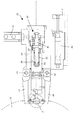
しかしながら、ジャーナルを振れ止め装置で保持する場合、クランクピンの周回運動精度はジャーナル部の真円度精度の影響を受ける。さらに、振れ止め装置で保持されたジャーナルとクランクシャフトの加工基準である両センタ穴、又は両端ジャーナル間で同軸度誤差がある場合は、クランクシャフトは回転に応じて変動する曲げ力を受ける。この力によりクランクピンの周回運動に誤差を生じて形状及び真円度に誤差が発生することになる。特に図2に示されるような、ジャーナル円周のほぼ120度毎の角度位置を保持するような三点支持式の振れ止め装置では保持力が高いため、ジャーナルを保持したときには回転中心にジャーナル軸線を確実に一致させることができるが、その反面、ジャーナルの真円度の影響を受けやすい。
よって、本発明の主たる目的は、クランクピンの周回運動誤差による真円度誤差を防止し、研削精度を向上させることにある。
【0006】
【課題を解決するための手段】
この発明は、上述した課題を解決するための研削方法を提供するものであり、その要旨は相対的に大きな負荷を伴う研削加工においてはクランクシャフトの撓みを生じさせないで高能率研削ができるように、クランクシャフトのジャーナルを振れ止めで保持して研削を行う。
一方相対的に小さな負荷の最終仕上げ加工においては、振れ止めのジャーナル保持を解除し、クランクシャフト加工基準の両センタ穴、又は両端ジャーナル間での2点支持でクランクシャフトを回転し、基準部に対して誤差の無い周回運動を行うピン部の研削加工を行う。
【0007】
【発明の実施の形態】
以下、本発明の実施の形態を図面に基づいて説明する。
以下、本発明の実施の形態を図面に基づいて説明する。図1は、本発明をクランクピン加工用の研削盤に適用した実施の形態を示し、ベッド1上にはその長手左右方向(Z軸方向)のZ軸案内レール2上に研削砥石台8を載置するZ軸テーブル6が送りねじ3により摺動自在に設けられ、Z軸テーブル6には、砥石14を回転自在に支持する砥石台8が後述するクランクシャフトWの径方向、より厳密には前記Z軸方向と直交する前後方向(X軸方向)に送りねじ12により摺動自在に設けられている。
【0008】
前記砥石台8の前方で長手方向に離間して主軸台17、心押台18が設置され、その間に工作物であるクランクシャフトWを左右一対のセンターにより支持している。主軸台18にはクランクシャフト回転駆動用のC軸サーボモータ19が設けられ、駆動ピン20によりクランクシャフトWの軸端を把持して回転駆動でき、その回転位置はモータ19の後端に設けたエンコーダ19Eにより検出され、一方心押台18はそのセンターによりクランクシャフトWの軸芯を押圧支持するように構成されている。
【0009】
前記各送りネジ3、12は、後述する数値制御装置により制御されるエンコーダ付サーボモータにより回転駆動される。すなわち、研削砥石台8を載置するZ軸テーブル6をZ軸方向に移動するための送りねじ3の左端部にはエンコーダ25E付きのサーボモータ25が設けられている。また、Z軸テーブル6上には、砥石台8の前後方向(X軸方向)摺動用の送りねじ12の端部にエンコーダ27E付きサーボモータ27が設けられている。砥石台8は、内臓した図略のビルトインモータにより砥石14を回転駆動できるように支持している。
【0010】
ベッド1上には三点支持式の振れ止め装置30がクランクシャフトWを挟んで砥石台8と反対側に配置されている。振れ止め装置30は、レストベース31上でZ方向にレストヘッド32を割り出し移動する送りねじ33及びエンコーダ付サーボモータ34が設けられている。
図2に示すようにレストヘッド32のハウジング35は、下部に油圧シリンダ36を備え、送りねじ33によって移動される基台37に対してクランクシャフトWの回転軸線に垂直方向(X方向)に往復移動する。
【0011】
ハウジング35内には、上下方向位置で主軸17により支持されたクランクシャフトWの回転軸線の高さ(即ち砥石台Hの砥石主軸の高さ)に一致する位置に形成された中空孔38に、滑動体39が前進・後退滑動自在に嵌合している。
ハウジング1から露出した滑動体39の前端には、第1支持腕40が固着されている。
中空孔38の後端には、駆動軸41が回転自在に支持されている。駆動軸41の先端側は、滑動体39の中心穴42内に突出し、滑動体39の中心穴42の後端開口側に嵌着された雌ねじスリーブ43に螺合したねじ部44が形成され、駆動軸41の回転にすることで滑動体39が中空孔38内で進退する。駆動軸41の後端側には、歯車機構45が取り付けられている。この歯車機構45は、ハウジング35の側面に取り付けられたサーボモータ46の出力軸に結合されている。
【0012】
ハウジング35の前面、第1支持腕40の上下方向には、一対の第2支持腕47と第3支持腕48が支持軸49,50と平行な軸線回り回転自在に設けられている。
【0013】
これら第2支持腕47と第3支持腕48は、油圧制御装置83に接続された図略の油圧シリンダによって支持軸49、50の軸線回りで第1支持腕40に対して接離するように旋回制御される。
レストヘッド35は、研削時において、例示される4気筒用クランクシャフトの場合、中央の3つ、つまり心押台18側から2〜4番目のジャーナルJ2、J3、J4と対向する位置へサーボモータ34により選択的に割り出される。この割り出し位置で、シリンダ36によってはハウジング35が前進することにより、予めシャーナル径に応じてサーボモータ46により位置調整された第1支持腕40がジャーナルに接触する。これとともに、油圧制御装置83からの油圧によって第2支持腕47及び第3支持腕48を閉じることで、図2に示されるようにジャーナルを挟み込んで、クランクシャフトWの撓みを防止する。
【0014】
本発明の実施例に係る研削盤の概略の構成は以上のようになっており、クランクシャフトWを主軸台17と心押し台18との間に支持し、研削時には左側Z軸テーブル6をサーボモータ25により砥石14がクランクピンP1〜P4と整列する位置に割出すとともに、レストヘッドをサーボモータにより、砥石14が割り出されたクランクピンに近傍したジャーナルの位置に割り出し、シリンダ36によってハウジング35を前進させ第1支持腕40をジャーナルに接触させるとともに第2支持腕47及び第3支持腕48を閉じてジャーナルを挟みんで、ジャーナルを回転中心に固定する。
次に主軸台17のサーボモータ19を回転しクランクシャフトWを回転させる。その際クランクシャフトWはそのジャーナルの軸芯上で回転されるので、加工箇所であるクランクピンはジャーナルの周りに周回運動する。そして、研削砥石台8をサーボモータ27により粗研削の送り量で前進させる。その際、加工箇所であるクランクピンは周回運動しているので、主軸サーボモータ19の回転と同期させて砥石台8を前後動させながら研削砥石14により研削加工を行う。この同期運動に重合してサーボモータ27により切込み前進運動を与え、徐々に粗加工寸法まで研削するように作動する。
【0015】
研削砥石14により粗加工寸法までクランクピンを研削加工すると、第2支持腕及び第3支持腕が開くとともに、ハウジングが後退して第1支持腕、第2支持腕、第3支持腕によるジャーナルの保持が開放される。
この間、クランクピンは停止することなくジャーナルの周りに周回運動し、研削砥石台8のサーボモータ27により仕上げ研削の送り量で前進させる。その際、加工箇所であるクランクピンは周回運動しているので、制御手段により主軸サーボモータ19の回転と同期させて砥石台8を前後動させながら研削砥石14により研削加工を行う。この同期運動に重合してサーボモータ27により切込み前進運動を与え、徐々に仕上げ加工完了寸法まで研削するように作動する。
なお、上記粗加工完了寸法に到達したときに砥石台8の送り量を切り替えることと、仕上げ加工寸法に到達して加工を完了することは定寸装置51によって行われる。この定寸装置51は、図3に示されるように砥石台8上に載置されている。
この定寸装置51は、研削加工中の旋回するクランクピンPに絶えず接触しながら追従して寸法測定を行う形式の公知の追従式定寸装置(例えば、イタリア、マーポス社製)である。砥石台8上の支持部材52に枢支され研削砥石14の前方に延びる第1アーム53の先端に第2アーム54が枢支され、更に第2アーム54の先端に約直角に採寸用の測定棒55が固定されている。測定棒55は、その下端に固定されてクランクピンPの外周に接触するVブロック56と、その中心に進退自在に設けられたプローブ57とからなる測定ヘッドを有し、この測定ヘッドはプローブ57の前進後退を検出して電気信号として出力する構造である。Vブロック56の先端にはガイド部材58が固定されており、Vブロック56がクランクピンPに係合するためのガイドの役目をしている。
【0016】
砥石台8上には、第1アーム53と一体の操作片59と当接して測定棒55を休止位置(2点鎖線位置)と測定位置(実線位置)とに移動するためにの油圧シリンダ60からなる作動装置が設けられている。第1アーム53の先端部下面から前方に突出する支持片61の突起62は、休止位置において第2アーム54の下面に当接してを第2アーム54を水平に保持するように働く。2点鎖線の休止位置から、油圧シリンダ60のピストン60aを戻すことにより測定棒55が徐々に降下し、まずガイド部材58がクランクピンPに接触し、ガイド部材58に沿ってクランクピンPがVブロック57に係合するようになっており、その時点において第2アーム54は支持片61の突起62から離れて自由に回動できるようになっている。
【0017】
次に、実施の態様の研削盤を制御する制御システムについて図4を参照して説明する。本制御システムは、数値制御装置70を備え、数値制御装置70は、CPU71、及び記憶装置であるROM73、RAM74を相互に接続して構成されている。CPU71は、インターフェース76を介してX軸モータ制御回路DUXに接続され、インターフェース78を介して、Z軸モータ制御回路DUZ、レスト装置30を制御するS軸モータ制御回路DUSとT軸モータ制御回路DUT、主軸モータ19を制御するC軸モータ制御回路DUC及びシーケンスコントローラ79に接続されている。これらモータ制御回路DUX、DUZ、DUS、DUT及びDUCは、対応するサーボモータ19、27、25、34及び36を駆動し、これらサーボモータのエンコーダ19E、27E、25E、34E及び36Eからそれぞれ帰還信号を受けるように接続されている。
【0018】
また、CPU71には、インターフェース80を介して、CRT及びテンキー等を備えた操作盤81が接続されている。ROM73には、システム制御プログラムなどが記億され、RAM74には加工制御プログラムなどが記憶されている。更にCPU71には研削砥石台8に設けられた定寸装置51の測定ヘッドがA−D変換器を含むインターフェース82を介して接続されている。
次に本発明の特徴である具体的な研削動作について、その動作を図4のフローチャートに沿って説明する。
【0019】
作業者によって主軸台17と心押台18の両センタ間にクランクシャフトWが取り付けられる。なお、クランクシャフト着脱時においては、砥石台8及びレストヘッド32は、共に後退した待機位置にあり、待機位置にあるレストヘッド32の第2支持腕47及び第3支持腕48は開いた状態にある。
この後、操作盤81より数値制御装置70に研削実行の指令がなされると図4のフローチャートの動作が実行され、RAM74内に形成される順序カウンタNが初期値”1”にセットされる(ステップ90)。次に、順序カウンタNが全てのクランクピンの研削が完了したことを示す”5”より大きいか否かが判定される。(ステップ92)この状態で順序カウンタNは”1”であるので判定が”NO”となり、次の処理としてテーブル割出しが実行される(ステップ94)。RAM74には図5に示す割り出し位置記憶テーブルIPMTが形成され、加工順序Nが特定される場合に加工すべきクランクピン及びレスト装置30が支持すべきジャーナルが操作盤81を用いて作業者により予め指定されている。この場合、加工順序が”1”であるので、サーボモータ25が動作され、砥石14をクランクピンP2と整列する位置にテーブル6が割り出され、続いて、サーボモータ19が動作されてクランクピンP2が図6の(イ)の位置として示す砥石側に最も接近する水平の加工開始位置へ割り出される(ステップ96)。
【0020】
次にサーボモータ34の動作により、レストヘッド32が中央のジャーナルJ3と整列する位置に割り出される。レストヘッドがジャーナルJ3と整列した位置に割り出されると、シーケンスコントローラより油圧制御装置83に対してレスヘッドのハウジングを前進させる指令が出力され、第1支持腕の先端がジャーナルJ3に接触する。これと同時に、サーボモータ27が動作され、研削砥石台8がクランクシャフトWに向かって早送り前進される。(ステップ98)この前進送り量は、研削砥石14がクランクピンP2及びジャーナルJ3と若干の隙間を有した位置で停止されるように予め設定されている。
【0021】
早送りが完了すると、続けて第2支持腕47、第3支持腕48を閉じる指令がされ、油圧制御装置83により所定の油圧力によって第2支持腕47、第3支持腕48がジャーナルJ3を挟み込むことで、ジャーナルJ3が主軸の回転軸心と一致した位置に固定される。(ステップ100)。
【0022】
次に研削砥石台8の粗研削送り実行される(ステップ102)。この粗研削においては、サーボモータ19とサーボモータ27がプロファイルデータ従って同期制御される。このプロファイルデータは、図6に示すように、クランクピンPの加工開始位置(イ)からの回転角(Θn)に対する砥石台8のクランクシャフト回転軸線からの位置(XΘ)を例えばクランクシャフト回転角0.5度毎に定めたもので、RAM74に予め登録されている。研削砥石台8用のサーボモータ27は、プロファイルデータに基づく進退運動に対し、粗研削送り、つまりクランクピンP2に対する研削砥石14の切り込みが重合され、これにより研削砥石14は、クランクピンP2の周回運動に伴って進退されながら徐々に切り込み前進される。
【0023】
この粗研削工程の途中において、図3に示す定寸装置51のシリンダ60がピストンロッド60aを後退してVヤゲン56をクランクピンP2に係合し測定を開始する。この測定開始司令は、シーケンスコントローラ79からの信号により実行される。この定寸装置の計測位置への動作は、図6の(ロ)の位置からクランクピンPが旋回下降し下降端に到達する間にVヤゲン56をクランクピンPに追跡させるように行われる。この場合、Vヤゲン56がクランクピンPにより正確に係合できるようにするため、クランクシャフトWの回転速度を低下しても良い。或いは、クランクピンPを図6の(ロ)の位相に一旦停止した状態で、Vヤゲン56の計測位置前進動作を実行させてもよい。
かくして、振れ止め装置30によりジャーナルJ3が保持されているため、クランクシャフトWの軸心がほぼ回転軸線に維持されると共に、特に研削抵抗によるクランクシャフトWの撓みは阻止され、三点支持振れ止め状態にあるクランクシャフトWは、外力の作用した場合にも安定した周回運動を行うことができる。
【0024】
このようにして、クランクピンP2の粗研削が進められ、この間測定ヘッドは、クランクピンP2の寸法を監視する。(ステップ104)クランクピンP2が所定寸法まで粗研削されると、次にシーケンスコントローラ79を介して油圧制御装置83に対してレスヘッド32のハウジング35を後退させる指令が出力され、第1支持腕40の先端がジャーナルJ3から離れる。続けて第2支持腕47、第3支持腕48を開く指令がなされ、これらの指令によってジャーナルJ3の振れ止め装置による固定が開放される。(ステップ106)。このときクランクシャフトWはセンター穴等の基準部でのみ保持された状態で周回運動を行う。即ち、振れ止めでジャーナル保持をした場合に発生するジャーナルの心円度不良の影響のない周回運動をする。この状態で仕上げ研削を実施する。(ステップ108)
【0025】
仕上げ研削は、研削砥石台8を粗研削送り速度よりも遅い切り込み速度で切り込み前進させ、この切り込み送りがプロファイルデータに基づく進退運動に重合され、これによりクランクピンP2はより遅い研削速度で仕上研削される(ステップ110)。なお、仕上げ研削における砥石台8の送りは粗研削に比較して非常小さいため、クランクシャフトをほとんど撓ませることなく研削が可能である。
【0026】
クランクピンP2が所定の仕上寸法に到達すると(ステップ112)、最終スパークアウト研削が、クランクシャフトWが所定回数回転する間実行され、(ステップ114)研削加工を終了する。
研削終了後、加工順位カウンタNに”1”を加算して(ステップ116)ステップ83に復帰し、ステップ94〜ステップ112の処理を加工順位カウンタが”4”より大きくなるまで上述したように繰り返すことで、残りのクランクピンJ1、J3、J4が研削される。そしてステップで加工順位カウンタNが”4”より大きくなると研削を終了し、砥石台8が原位置に戻り(ステップ118)処理を終了する。
【0027】
このように、粗研削時は砥石14による研削抵抗が大きいためクランクシャフトが撓んで研削精度が悪くなることをジャーナルが支持されることで防止し、仕上げ研削では、砥石よる研削抵抗が小さくクランクシャフトが撓むことがないことから、ジャーナルの真円度によってクランクピンの周回運動が影響されることを防止するために振れ止め装置30でジャーナル支持を行わず、クランクシャフトWの両端を主軸台17と心押し台18のセンタによってのみ支持するようにした。これによってクランクピンを高精度に研削することができる。
特に本実施の形態に示した三点式の振れ止め装置30を用いた研削盤では、振れ止め装置30のジャーナルの保持力が高いので有効である。
【0028】
なお、上記実施の形態では粗研削時にクランクピンの最も近い位置にあるジャーナルを支持していたが、これに限られるものでなく、比較的たわみの小さいクランクシャフト(長さが短い場合を含む)では、クランクシャフトの中央に位置するジャーナルを研削するクランクピンの位置に係わらず支持するようにすれば、レストヘッドを移動する必要がなくなるので、サーボモータやボールねじを設ける必要がなくなり、研削盤を簡素化することができる。
また、振れ止め装置を複数設けてもよい。さらに、仕上げ研削時に振れ止め支持を完全に解放しないで、仕上げ研削時に油圧制御装置83の油圧を下げ、振れ止め装置によるジャーナルの保持力(例えば、粗研削時の保持力の20%程度)に低下させて研削するようにしてもよい。
なお、上記実施の形態では、研削サイクルを粗研削と仕上げ研削との2つのみで説明したが、仕上げ研削には精研削、微研削を含むものである。
【0029】
【発明の効果】
以上のように、本発明の請求項1のように粗研削時は振れ止め装置によってジャーナルを支持し、仕上げ研削時ではクランクシャフトの両端支持のみとすることで、粗研削時にクランクシャフトのたわみ、脱落等を防止して研削力の大きな高能率研削が可能となる。一方仕上げ研削時にはジャーナル部の精度による影間を受けないで、高精度のピン研削ができる。この結果、短時間に高精度のピン研削加工が可能となる。また、請求項2のように研削するピンの最も近い位置のジャーナルを支持するようにすれば、たわみを最も効果的に防止することができる。また、請求項4のようにすれば、粗研削時にクランクシャフトのたわみ、脱落等を防止して研削力の大きな高能率研削が可能な一方、仕上げ研削時にはジャーナル部の精度による影間を受けないで、高精度のピン研削ができる研削盤とすることができる。さらに請求項5のようにすれば、たわみを最も効果的に防止する研削盤とすることができ、さらに高精度の研削が可能な研削盤とすることができる。
【図面の簡単な説明】
【図1】本発明による研削盤の実施の態様であるクランクピン研削盤の平面図。
【図2】クランクピン研削盤に使用される振れ止め装置のレストヘッドを示す側面図。
【図3】クランクピン研削盤に使用される定寸装置を示す側面図。
【図4】クランクピン研削盤の数値制御装置が実行するシステム制御プログラムのフローチャート。
【図5】数値制御装置のRAMに形成される割り出し位置記憶テーブルを示す説明図。
【図6】クランクピンの旋回位相と砥石の送り位置の関係を示す説明図。
【符号の説明】
1:ベッド、W:クランクシャフト(工作物)、17:主軸台、18:心押し台、8:砥石台、14:砥石、30:振れ止め装置、32:レストヘッド、40:第1支持腕、47:第2支持腕、48:第3支持腕70:数値制御装置[0001]
BACKGROUND OF THE INVENTION
The present invention relates to a grinding machine provided with a touch-stop device for supporting a journal of a crankshaft and a grinding method thereof. More specifically, the present invention relates to a grinding machine and a grinding method provided with a steady rest device for supporting a journal for rotating a crankshaft around a journal to grind a crankpin.
[0002]
[Prior art]
In a grinding machine that grinds the crankpin of the crankshaft, it rotates around the journal shaft center of the crankshaft according to the machining program set in the numerical control device, and the crankpin rotates around the journal. The forward / backward feed is controlled synchronously with the rotation of the crankshaft so that the wheel head can be advanced and retracted in response to changes in the angular position during the movement.
[0003]
In general, the crankshaft has low rigidity and generates a deflection when subjected to grinding resistance by a grinding wheel. For this reason, in a grinding machine that rotates around the journal axis as described above to grind the crankpin, the entire crankshaft is deflected by the grinding resistance applied to the crankpin and the journal axis is displaced from the center of rotation. become. If grinding of the crankpin is continued in this state, an error will occur in the shape and roundness of the crankpin, and if the grinding resistance is further increased, the entire crankshaft will vibrate greatly, causing the crankshaft to fall off and grinding itself. May not be possible.
[0004]
Conventionally, when the workpiece is a simple cylinder, a tapping device that presses the crankshaft from the direction opposite to the pushing direction of the grinding wheel is used as a method for preventing the deflection. However, in the grinder that grinds the crank pin by rotating around the journal axis as described above, the crank shaft rotates around the journal axis, so that the crank pin rotates. It was difficult to press. For this reason, in order to prevent the journal axis from deviating from the center of rotation, the journal is held by a touch-stop device to prevent crankshaft deflection.
[0005]
[Problems to be solved by the invention]
However, when the journal is held by the steady rest device, the rotational motion accuracy of the crankpin is affected by the roundness accuracy of the journal portion. Further, when there is a coaxiality error between the center hole, which is the processing standard of the journal held by the steady-rest device and the crankshaft, or between both end journals, the crankshaft receives a bending force that varies with rotation. This force causes an error in the revolving motion of the crankpin and an error in shape and roundness. In particular, as shown in FIG. 2, the three-point support type steady rest device that holds the angular position of every 120 degrees of the journal circumference has a high holding force. However, it is easy to be affected by the roundness of the journal.
Therefore, a main object of the present invention is to prevent roundness error due to circular motion error of the crankpin and improve grinding accuracy.
[0006]
[Means for Solving the Problems]
The present invention provides a grinding method for solving the above-described problems, and the gist thereof is to enable high-efficiency grinding without causing bending of the crankshaft in grinding processing with a relatively large load. Grind by holding the crankshaft journal with a steady rest.
On the other hand, in the final finishing process with a relatively small load, the journal holding of the steady rest is released and the crankshaft is rotated with two-point support between both center holes of the crankshaft machining reference or both end journals. On the other hand, the pin part that performs a circular motion without error is ground.
[0007]
DETAILED DESCRIPTION OF THE INVENTION
Hereinafter, embodiments of the present invention will be described with reference to the drawings.
Hereinafter, embodiments of the present invention will be described with reference to the drawings. FIG. 1 shows an embodiment in which the present invention is applied to a grinding machine for machining a crankpin. A
[0008]
A
[0009]
Each of the
[0010]
On the
As shown in FIG. 2, the housing 35 of the
[0011]
In the housing 35, a
A
A
[0012]
In the front surface of the housing 35 and in the vertical direction of the
[0013]
The
In the case of a four-cylinder crankshaft exemplified in the grinding, the rest head 35 is moved to three positions in the center, that is, a position facing the second to fourth journals J2, J3, J4 from the
[0014]
The general configuration of the grinding machine according to the embodiment of the present invention is as described above. The crankshaft W is supported between the
Next, the
[0015]
When the crankpin is ground to the rough machining size by the grinding
During this time, the crankpin moves around the journal without stopping, and is advanced by the feed amount of finish grinding by the
Note that the sizing
This sizing
[0016]
A
[0017]
Next, a control system for controlling the grinding machine of the embodiment will be described with reference to FIG. The present control system includes a numerical control device 70, and the numerical control device 70 is configured by connecting a CPU 71 and
[0018]
An
Next, a specific grinding operation which is a feature of the present invention will be described with reference to the flowchart of FIG.
[0019]
A crankshaft W is attached between the centers of the
Thereafter, when a grinding execution command is issued from the
[0020]
Next, by the operation of the
[0021]
When the fast-forwarding is completed, the
[0022]
Next, rough grinding feed of the
[0023]
In the course of this rough grinding process, the
Thus, since the journal J3 is held by the steadying
[0024]
In this way, the rough grinding of the crank pin P2 proceeds, and during this time the measuring head monitors the dimensions of the crank pin P2. (Step 104) When the crank pin P2 is roughly ground to a predetermined dimension, a command to retract the housing 35 of the
[0025]
In the finish grinding, the
[0026]
When the crank pin P2 reaches a predetermined finishing dimension (step 112), final spark-out grinding is performed while the crankshaft W rotates a predetermined number of times (step 114), and the grinding process is completed.
After grinding, “1” is added to the machining order counter N (step 116), the process returns to step 83, and the processing of
[0027]
In this way, since the grinding resistance by the
In particular, the grinding machine using the three-
[0028]
In the above embodiment, the journal located closest to the crankpin is supported during rough grinding. However, the present invention is not limited to this, and a crankshaft having a relatively small deflection (including a case where the length is short). Then, if the journal located in the center of the crankshaft is supported regardless of the position of the crankpin that grinds, there is no need to move the rest head, so there is no need to provide a servo motor or ball screw, and the grinding machine Can be simplified.
A plurality of steady rest devices may be provided. Furthermore, without completely releasing the steady rest support during finish grinding, the hydraulic pressure of the
In the above embodiment, only two grinding cycles of rough grinding and finish grinding have been described. However, finish grinding includes fine grinding and fine grinding.
[0029]
【The invention's effect】
As described above, as described in
[Brief description of the drawings]
FIG. 1 is a plan view of a crankpin grinder as an embodiment of a grinder according to the present invention.
FIG. 2 is a side view showing a rest head of a steady rest device used in a crankpin grinding machine.
FIG. 3 is a side view showing a sizing device used in a crankpin grinding machine.
FIG. 4 is a flowchart of a system control program executed by a numerical control device of a crankpin grinder.
FIG. 5 is an explanatory diagram showing an index position storage table formed in the RAM of the numerical controller.
FIG. 6 is an explanatory view showing a relationship between a turning phase of a crank pin and a feed position of a grindstone.
[Explanation of symbols]
1: Bed, W: Crankshaft (workpiece), 17: Main spindle, 18: Tailstock, 8: Grinding wheel, 14: Grinding wheel, 30: Stabilizer, 32: Rest head, 40: First support arm 47: second support arm 48: third support arm 70: numerical control device
Claims (5)
Priority Applications (1)
| Application Number | Priority Date | Filing Date | Title |
|---|---|---|---|
| JP2001100988A JP3982196B2 (en) | 2001-03-30 | 2001-03-30 | Grinding machine equipped with steady rest and grinding method thereof |
Applications Claiming Priority (1)
| Application Number | Priority Date | Filing Date | Title |
|---|---|---|---|
| JP2001100988A JP3982196B2 (en) | 2001-03-30 | 2001-03-30 | Grinding machine equipped with steady rest and grinding method thereof |
Publications (2)
| Publication Number | Publication Date |
|---|---|
| JP2002292546A JP2002292546A (en) | 2002-10-08 |
| JP3982196B2 true JP3982196B2 (en) | 2007-09-26 |
Family
ID=18954372
Family Applications (1)
| Application Number | Title | Priority Date | Filing Date |
|---|---|---|---|
| JP2001100988A Expired - Lifetime JP3982196B2 (en) | 2001-03-30 | 2001-03-30 | Grinding machine equipped with steady rest and grinding method thereof |
Country Status (1)
| Country | Link |
|---|---|
| JP (1) | JP3982196B2 (en) |
Families Citing this family (3)
| Publication number | Priority date | Publication date | Assignee | Title |
|---|---|---|---|---|
| EP1440765B1 (en) | 2003-01-21 | 2006-01-04 | Toyoda Koki Kabushiki Kaisha | Cylindrical grinding machine |
| JP5056066B2 (en) * | 2007-02-23 | 2012-10-24 | 株式会社ジェイテクト | Grinding method for work journal |
| CN115890264B (en) * | 2023-03-02 | 2023-05-02 | 潍坊胜利石化机械有限公司 | Cutting device for processing large-sized crankshaft |
-
2001
- 2001-03-30 JP JP2001100988A patent/JP3982196B2/en not_active Expired - Lifetime
Also Published As
| Publication number | Publication date |
|---|---|
| JP2002292546A (en) | 2002-10-08 |
Similar Documents
| Publication | Publication Date | Title |
|---|---|---|
| JP3787248B2 (en) | Method and apparatus for controlling sizing of machine tool | |
| EP1795300B1 (en) | Mounting structure for measuring device and grinding machine with the structure | |
| US6711829B2 (en) | Method for measuring work portion and machining method | |
| KR20020082403A (en) | Method and appatatus for grinding eccentric cylindrical portions of workpiece with diameter measuring device | |
| EP1004396A1 (en) | Machine tool and machining method | |
| JPH02292147A (en) | Dividing of phase | |
| JPH06246601A (en) | Grinding method | |
| JP3982196B2 (en) | Grinding machine equipped with steady rest and grinding method thereof | |
| US7901268B2 (en) | Method for grinding journal section of workpiece | |
| JP2002052465A (en) | Steady rest device | |
| CN109605102B (en) | Machine tool | |
| KR101518061B1 (en) | Machine tool that oval processing is available | |
| JP3687770B2 (en) | Method and apparatus for controlling sizing of twin head grinder | |
| JP3528197B2 (en) | Grinding equipment | |
| JP4539557B2 (en) | Method and apparatus for controlling sizing of machine tool | |
| JP3836098B2 (en) | Crank pin grinding method and grinding apparatus | |
| JP4400226B2 (en) | Grinding method and grinding apparatus | |
| JP2003136379A (en) | Double-head grinding machine | |
| JP3866951B2 (en) | Processing method and processing apparatus | |
| JP3834493B2 (en) | Compound grinding method and apparatus | |
| JP2003094293A (en) | Abnormality detection method for measurement device of machining device and machining device | |
| JP2511775B2 (en) | Touring device | |
| JP2000218479A (en) | Method of and device for grinding cylinder | |
| JP2659134B2 (en) | Chuck for holding crankshaft | |
| JPH10291158A (en) | Sizing device of crankshaft finishing machine |
Legal Events
| Date | Code | Title | Description |
|---|---|---|---|
| A711 | Notification of change in applicant |
Free format text: JAPANESE INTERMEDIATE CODE: A712 Effective date: 20060228 |
|
| A131 | Notification of reasons for refusal |
Free format text: JAPANESE INTERMEDIATE CODE: A131 Effective date: 20060425 |
|
| A521 | Written amendment |
Free format text: JAPANESE INTERMEDIATE CODE: A523 Effective date: 20060623 |
|
| A131 | Notification of reasons for refusal |
Free format text: JAPANESE INTERMEDIATE CODE: A131 Effective date: 20060829 |
|
| A521 | Written amendment |
Free format text: JAPANESE INTERMEDIATE CODE: A523 Effective date: 20061030 |
|
| A131 | Notification of reasons for refusal |
Free format text: JAPANESE INTERMEDIATE CODE: A131 Effective date: 20070308 |
|
| A521 | Written amendment |
Free format text: JAPANESE INTERMEDIATE CODE: A523 Effective date: 20070507 |
|
| TRDD | Decision of grant or rejection written | ||
| A01 | Written decision to grant a patent or to grant a registration (utility model) |
Free format text: JAPANESE INTERMEDIATE CODE: A01 Effective date: 20070612 |
|
| A61 | First payment of annual fees (during grant procedure) |
Free format text: JAPANESE INTERMEDIATE CODE: A61 Effective date: 20070625 |
|
| FPAY | Renewal fee payment (event date is renewal date of database) |
Free format text: PAYMENT UNTIL: 20100713 Year of fee payment: 3 |
|
| R150 | Certificate of patent or registration of utility model |
Free format text: JAPANESE INTERMEDIATE CODE: R150 |