JP3979668B2 - Method and apparatus for measuring fluid electrical factors - Google Patents
Method and apparatus for measuring fluid electrical factors Download PDFInfo
- Publication number
- JP3979668B2 JP3979668B2 JP52501397A JP52501397A JP3979668B2 JP 3979668 B2 JP3979668 B2 JP 3979668B2 JP 52501397 A JP52501397 A JP 52501397A JP 52501397 A JP52501397 A JP 52501397A JP 3979668 B2 JP3979668 B2 JP 3979668B2
- Authority
- JP
- Japan
- Prior art keywords
- fluid
- heat exchange
- temperature
- electrical
- test
- Prior art date
- Legal status (The legal status is an assumption and is not a legal conclusion. Google has not performed a legal analysis and makes no representation as to the accuracy of the status listed.)
- Expired - Fee Related
Links
Images


Classifications
-
- G—PHYSICS
- G01—MEASURING; TESTING
- G01N—INVESTIGATING OR ANALYSING MATERIALS BY DETERMINING THEIR CHEMICAL OR PHYSICAL PROPERTIES
- G01N27/00—Investigating or analysing materials by the use of electric, electrochemical, or magnetic means
- G01N27/02—Investigating or analysing materials by the use of electric, electrochemical, or magnetic means by investigating impedance
- G01N27/04—Investigating or analysing materials by the use of electric, electrochemical, or magnetic means by investigating impedance by investigating resistance
- G01N27/06—Investigating or analysing materials by the use of electric, electrochemical, or magnetic means by investigating impedance by investigating resistance of a liquid
- G01N27/07—Construction of measuring vessels; Electrodes therefor
-
- G—PHYSICS
- G01—MEASURING; TESTING
- G01N—INVESTIGATING OR ANALYSING MATERIALS BY DETERMINING THEIR CHEMICAL OR PHYSICAL PROPERTIES
- G01N27/00—Investigating or analysing materials by the use of electric, electrochemical, or magnetic means
- G01N27/02—Investigating or analysing materials by the use of electric, electrochemical, or magnetic means by investigating impedance
- G01N27/04—Investigating or analysing materials by the use of electric, electrochemical, or magnetic means by investigating impedance by investigating resistance
- G01N27/06—Investigating or analysing materials by the use of electric, electrochemical, or magnetic means by investigating impedance by investigating resistance of a liquid
Abstract
Description
本発明は流体の電気的因子を測定する方法に関するものである。特に、本発明は液体の電気伝導度の測定に関する。
電気伝導度は液体の特性の1つであり、該特性を用いて種々の液体の同定を行なったり、液体媒体内の気泡および固体を含んだ、溶液または異なる材質の混合物のある種の成分の濃度を測定したりすることが可能である。そのような濃度測定の原理は、該当成分がベース物質の電気伝導度と異なる伝導度を有しているということである。
電気伝導度は該当液体中に電流を流し、当該液体に対して生じた電圧降下を電流で除した電気抵抗を計算することによって測定される。これは伝導度セルと呼ばれる装置によって実施されるが、該セルは測定すべき液体によって隔てられた少なくとも2本の電極を含んでいる。電流は電極を介して液体中に出入りするが、同電極はそれらが互いに対して液体通路から隔離されるよう通常は配設されている。
電気的コンダクタンスは電気抵抗の逆数として計算される。電気的コンダクタンスは電気伝導度のみに依存するのではなく、液体中の電気的通路および任意の付加的電気通路(これは通常最小に押えられる)の幾何学的形状にも依存する。多くの場合、コンダクタンスCは等式(1)によって示すように、単純な定数K(これは通常セル定数と呼ばれる)によって伝導度ρと関連している。
ρ=KC ……(1)
この関係式は簡単な電気理論から導かれるものであり、該理論はコンダクタンスが伝導度×導体断面積÷導体長さに等しいということを述べている。言葉を換えるならば、セル定数は導体長さを導体横断面積で割ったものに等しい。通常、セル定数は既知の伝導度の液体、典型的には塩化カリウムによって導体セルを較正することによって求められる。
電極が分極化し、過剰の(または不足の)電荷が流体に電気信号が出入りする地点およびそのまわりにおいて誘起されるのを防止するためには、直流の代りに交流を至便的には使用することが出来る。
伝導度セルは流れる液体を受容するか、用途の性質によっては液体の静的プールを受容するように配設することが出来る。
液体の伝導度は温度に依存しており、1℃あたり約2%の変化が比較的に典型的である。多くの伝導度測定装置においては、したがって、温度プローブを用いて温度を測定し、実際の測定温度と基準温度(しばしば25℃)との差に対する修正を施すことが行なわれる。
しかしながら、温度の補正を正確に行なうことは幾つかの理由から困難である。理由の第1は、温度が測定される地点および時点が(一般的には)伝導度の測定される地点および時点とは同一でないということである。かくして、温度測定と伝導度測定の間において温度の変化があると、これは誤差に結びつく。この問題は更に、温度測定および伝導度測定が通常測定技法の副産物として熱を発生してしまうという事実によって悪化させられてしまう。低い流量においては、これらの加熱効果は流体の温度に対してより大きな影響をもたらし、同時に、温度プローブはそれによって液体からの熱の出入りが生じないようにするために、同温度プローブは外気から遮断しなければならないという結果をもたらす。しかしながら、流量が低くなればなる程、これらの問題によって生ずる誤差が大きくなるので、既存の技法によって得ることの出来る精度は、流量が減少するにつれて悪化する。
これらの問題はまた、温度が正確に知られていなければならない時には、セルの較正にも影響を及ぼす。このことは、測定プロセス全体において誤差は試験液体の伝導度測定の時点においてのみではなく、2回生ずるという事を意味している。加えるに、もしも温度による伝導度の変化が較正液体および試験液体の両者に対して正確に知られていないとすれば、温度補正プロセスにおいて更なる誤差が生ずる可能性がある。
伝導度セルの付加的問題点は、もしも正確な性能を保持しようとした場合、セル定数が時間とともに変化する可能性があり、再較正が必要とされるということである。
WO−A−9604401は分解後および未分解領域の溶液の伝導度差を測定するための方法および機器を開示している。本発明もまたそのような用途に適用可能であり、WO−A−9604401の全開示事項を本願に引用する。
本発明の1つの特徴によれば、次の構成に成る、試験流体の電気的因子を測定する機器が提供される。
それは、試験流体の電気的因子を基準流体の電気的因子と比較して決定するための機器であって、試験流体および基準流体を受容するようになった測定セル手段と、試験流体および基準流体と熱的に近接させて一次熱交換流体を流すための熱交換手段とを含む。熱交換手段は、一次熱交換流体を受容するための容器と、試験流体および基準流体が流れる2つのチューブとを有する。この機器において、熱交換手段の容器は、一方の表面を測定セル手段の外面に接触させ、他方の表面を一次熱交換流体の流れに接触させた金属壁を有し、これにより、測定セル手段は熱交換手段の外側にある。測定セル手段は2つのフロー通路を備え、フロー通路は、一方が試験流体用で他方が基準流体用であって、これら試験流体および基準流体の電気的因子をほぼ同時に測定するように配置される。
別の特徴によると、本発明は、上記機器によって試験流体の電気的因子を測定する方法を提供し、この方法は、上記チューブを経て試験流体と基準流体を別個に受容する測定セル手段を用意する段階と、試験流体と基準流体を測定セル手段内に導入する前に、それら流体の温度を、上記熱交換手段を用いて均等化する段階と、試験流体と基準流体がほぼ同じ温度である間に、これら試験流体と基準流体の電気的因子をほぼ同時に測定する段階とを含む。
このように、較正用流体および試験流体の温度を正確に測定しようとする代りに、2つの流体の電気的伝導度を、好ましくは互いに実質的に同時に、互いに熱的近接状態にある一対のセルを用いて、測定し、それら流体間に実質的な温度差が存在出来ないようにしてやるのが良い。かくすれば、温度に関係して発生する誤差の大部分が相殺され、温度測定に起因する熱の発生も生じない。
2つの液体をそれぞれのセルに入れた時に互いにそれらの温度が等しくなることを保証するために、2つの液体は任意選択的に、やはりセルの温度をコントロールするのに用いられるのが好ましい一対の熱交換器二次コイル中を通過させることが出来る。セル内の液体の温度は熱交換器の一次流路内の液体の温度を測定することにより、間接的に測定することが可能である。一次流路中の流量は一般的には高い可能性がある。何故ならば、一次液体は再循環可能であるのに対して、試験流体はしばしば限定された量しか得られないからである。このことは前述の限定ないし制限が無ければ、温度はより容易に測定可能であることを意味している。
前述したように、2つの好ましい作動モードが可能である。すなわち、基準液体をその電気伝導度が正確な条件下で特性化されており、各測定に対して十分な量および時間が与えられる較正液体とするモードと、差分測定がなされる第二のモードとである。この差分モードは特に液体を2つの流路内に分割可能で、一方の流路の伝導度が両流路の伝導度を比較する以前に何らかのプロセスによって修整してやることが出来る場合に有用なモードである。この場合には、重要な因子となるのは(伝導度の絶対値よりは)一方の流路を処理することによって誘起される変化の方である。
第1のケースにおいて、温度は(直接的または間接的に)、以下の解析で示すように、測定される必要が無い。
今セルの電気伝導度を以下の等式であらわすとしよう。
ρa=ρa25+αa(Ta−25) ……(2)
ここに、ρa=セルa内で測定された電気伝導度
Ta=セル内の温度
ρa25=25℃におけるセルa内の流体の電気伝導度
αa=電気伝導度の温度による変化率
この等式は単一セルによる慣用測定において用いられるものであり、温度測定に誤差があると、それは直接伝導度の誤差に通ずるということが理解されよう。
ツインセル測定においても、類似の等式を第2のセルに対してあてはめることが出来る。
ρb=ρb25+αb(Tb−25) ……(3)
ここに、ρb=セルb内で測定された電気伝導度
Tb=セル内の温度
ρb25=25℃におけるセルb内の流体の電気伝導度
αb=電気伝導度の温度による変化率
TaおよびTbが等しいとすれば、これらの2つの等式を組合せて、2つのセル測定における値並びに既知の特性値により、温度の情報が無くてもセルb内の流体の伝導度をあらわす式とすることが出来る。かくして25℃を基準としてのセルb内の流体の伝導度は次式であらわされる。
ρb25=ρb+(ρa25−ρa)αb/αa ……(4)
第2の作動モードとして、やはりTa=Tbなる前提条件があてはまるとして、25℃を基準とした差分ρb25−ρa25は次式であたえられる。
ρb25−ρa25=ρb−ρa+25(αb−αa)−T(αb−αa)…(5)
この式は完全に温度に関して独立な式ではないが、温度を得る際の必要精度は単一セル装置よりも低くて良い。何故ならば、αbおよびαaは通常互いに等しいかまたは極めて近い値であるからである。このことは前述した間接的温度測定手法が特に適しているということを意味している。
類似の分析手法は例えばキャパシタンスまたは誘電損失係数のような他の電気的因子の測定に適用可能である。
同一装置内で2つのセルを使用することにより、2つのセルの互いに対する再消去ということも可能になる。このことは、セル定数の変化を検出し、再較正すること無しに補償を実施してやることが出来るということを意味している。
前述したように、前記2つのセルは好ましくは互いに対して熱的に極めて近接した関係にあり、このことはそれらセルをして高い熱伝導度を有するも低い電気伝導度を有する材質から作成し、電極が(液体中の通路を除いて)互いから絶縁されていることを保証することによって最も好適に実現される。特に適当な材質はアルミナセラミックおよびサファイアまたはガラスのような絶縁被覆を備えた金属である。熱的近接性はまたセルの流路間の距離を短かくし、構造体全体をして熱流に関して対称形とし、一方のセルから他方のセルへと著しい熱の流れが発生しないようにする(そうでないと温度差が発生する)ことによっても促進させることが出来る。更には、セル組立体全体を、好ましくは同セルを熱交換器の熱伝導性の壁に取付けることによって、該熱交換器の一次側に対して熱的に近接した状態で配置してやるのが良い。
セル内の液体中の電気的通路のコンダクタンスの測定は慣用的手段で実施可能であり、したがって詳細には説明しないことを理解されたい。
本発明の他の好ましい特徴は請求の範囲において定義されている。
次に、純粋に例示の目的をもって付図を参照し、本発明の好ましい実施例を説明する。付図において、
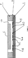
図1はセルおよび熱交換器の展開図、
図2は図1の線II−IIに沿って眺めた、セルおよび熱交換器の横断面図、
図3は線II−IIと平行に眺めた、測定セルの横断面図、
図4はプレート8の平面図である。
図1から図4に示された実施例はチューブ9aおよび9bを経由して熱交換器の二次側に進入する、試験液体の観点からまず考察される。これらのチューブは十分に長いので、2つの液体をして狭い誤差範囲内で互い同士において、かつまた一次熱交換器液体と同一の温度に到達せしめることが保証される。前記チューブは鋼のような熱伝導性の材質から作られている。というのは、こうすることにより温度が安定するのに要するチューブの長さを短くすることが出来るからである。チューブ9aおよび9bはそれらが熱的に近接した関係を保持できるようコイル状に巻かれている。こうすることにより、それらのチューブ間に温度の差異が誘起される可能性を低減させることが出来る。
これらのチューブは、熱交換器から、直接セル頂部プレート2内へと通過している。前記セルはチューブを位置決めする孔を備えているとともに、接着剤または他の適当な手段装置によってシールされていなければならない。これらの孔を通過した後、流体は中間プレート3内のフロー溝に進入し、フロー通路17(図3および図4)内かつ底部プレート1上の電極上を流れる。液体は次に頂部プレート中から出口チューブ10aおよび10b内へと流れ戻る。該チューブは外部へと直接通過していても良いし、それがより至便であるならば最初に熱交換器中を通過しても良い。出口チューブ10aおよび10bもまたセル頂部プレート2に関してシールされている。
チューブ9a,9b,10aおよび10bが隔壁プレート8中を通過する地点においては、一次熱交換器流体の漏洩を防止するために更なるシールが用いられている。
クランププレート6およびねじ7隔壁内のタップねじの助けにより、底部プレート1、中間プレート3および頂部プレート2を隔壁8へと保持せしめている。加えるに、エポキシ樹脂接着剤のような非電導性のシーラントを採用して、これらの部品の各々間にシール作用を確立するとともに、一方のフロー通路から他方のフロー通路へと流体が流れないようにしてやることが可能である。前記シーラント層は最適には出来る限り薄肉にして、全てのこれらのセル部品が出来る限り同一の温度付近に保持されることを保証するのが良い。
図2および図4に示すように、隔壁8内には切れ目18が設けられ、一次熱交換器流体がセル頂部プレート2と直接的熱接触作用を保持することを保証している。前記隔壁は好ましくは鋼または別の適当な材料のような熱伝導性の材料から作られており、好ましくは出来るだけ薄肉のものとし、頂部プレート2に対するシールを保持するという必要性と両立する熱接触作用を確保するのが良い。白金抵抗温度計のような温度プローブ11を隔壁8内に配置して、一次流体温度を測定することが出来る。
熱交換器一次流体はカバー12内にあり、カバー12はねじ13およびナット14およびガスケット(図示せず)のようなシールによって隔壁に保持されている。カバー12は至便にはポリプロピレンのようなポリマー材質から製作することが出来る。取入口19および取出口20がカバー12内の図2の面内に設けられており、一次流体は一次回路に進入、退出し、プロセス内のコイル9aおよび9b上を通過する。これらの接続部分は一次流体が図2の面内に進入、退出するよう配設されているのが好ましい。前記面は中間プレート3内の2つのフロー溝間中央に位置しており、隔壁8の面と垂直をなしている。構造体全体はこの面のまわりにおける熱的非平衡性を減少するように設計されている。
ねじ16によって保持されている付加的カバー15は、セル部品1,2および3をして外気と遮断し、セルおよび一次流体を類似の温度に保持するとともに、前述の平面のまわりの熱的対称性をも維持するように設計されている。セル部品のまわりの空気が熱交換器の温度近くに保持されることを保証するために、一次液体はカバー15中を通すか、カバーとクランププレート6の間のスペースを通すか、またはクランププレート6中を通すことさえ可能である。このことは、しかしながら、通常は必要とされない微修整である。
セル底部プレートは真空堆積させた金、白金または当業界周知の他の物質とすることの出来る、電極4に対する基板を提供している。リードワイヤ5は電極への、或いは電極からの電気的信号を搬送する。前記電極の形状は当業界既知の任意のものとすることが出来、例えば(溝当り)2つの電極を設けるという最も単純なものにすることも出来るが、この構造は高精度測定には理想的なものではない。適当な構造は、慣用の4電極測定構造であり、この場合、外側電極対は電力を送給するのに用いられ、内側対は検出のために用いられる。
図3に示す実施例においては、7電極構造体が示されており、この構造体は一方の極性の中央電極4Aと、該電極と反対極性の2つの外側電極4Bとを有している。抵抗は、内側電極4Aおよび最外側電極4Bの間の電流を測定し、i)電極4C間の電圧、ii)電極4D間の電圧を標準的態様で測定することにより決定される。
セル部品1,2および3は最適には、電気絶縁性であるも、熱良導性であるアルミナまたはサファイアのような材質から製造される。ポリマーおよびガラスを含む他のより安価な材質を用いることも可能であるが、性能はそれ程良好ではない。
前述の装置は以下の作動条件について設計されたものであり、以下のような仕様を有している。
伝導率:0〜50mS/cm(25℃において)
精 度:5μs/cm
一次流量:500ml/分
二次流量:1ml/分(1溝当り)
取入口温度間の差の最大値:10℃
公称のセル定数:50cm-1
セルの溝幅:1mm
セルの溝高さ:0.5mm
セルのゲージ長さ:2.5mm
二次チューブ長さ:800mm
二次チューブ内径:1mm
二次チューブ外径:1.6mm
本発明は液体内の粒状物質の濃度を測定するための分析機器に用いるのに特に適している。基本的には、異なる電気伝導度を有する別の物質へと(例えば化学反応によって)変換することの出来る物質はすべてそのような装置で用いるのに適している。別の用途としては、実験室または工業的工程において用いる液体のための専用伝導率メータが挙げられる。別の用途には他の慣用のセルの較正のための基準メータが挙げられる。
本発明は純粋に例示の目的で述べられており、詳細部の変更、修整は本発明の範囲内でなすことが可能である。例えば、並列状態にある2つまたはそれ以上の測定セルを1つの共通の熱交換器へと熱的に接続してやることが出来る。The present invention relates to a method for measuring an electrical factor of a fluid. In particular, the present invention relates to measuring the electrical conductivity of liquids.
Electrical conductivity is one of the properties of liquids, which can be used to identify various liquids, and for certain components of solutions or mixtures of different materials, including bubbles and solids in liquid media. It is possible to measure the concentration. The principle of such concentration measurement is that the relevant component has a conductivity different from that of the base material.
The electrical conductivity is measured by passing an electric current through the liquid and calculating an electric resistance obtained by dividing a voltage drop generated with respect to the liquid by the electric current. This is performed by a device called a conductivity cell, which contains at least two electrodes separated by the liquid to be measured. Current flows in and out of the liquid through the electrodes, which are usually arranged such that they are isolated from the liquid passage relative to each other.
Electrical conductance is calculated as the reciprocal of electrical resistance. The electrical conductance is not only dependent on electrical conductivity, but also on the geometry of the electrical path in the liquid and any additional electrical paths (which are usually kept to a minimum). In many cases, the conductance C is related to the conductivity ρ by a simple constant K (which is usually called the cell constant), as shown by equation (1).
ρ = KC (1)
This relationship is derived from a simple electrical theory, which states that conductance is equal to conductivity × conductor cross-sectional area ÷ conductor length. In other words, the cell constant is equal to the conductor length divided by the conductor cross-sectional area. Usually, the cell constant is determined by calibrating the conductor cell with a liquid of known conductivity, typically potassium chloride.
Use AC instead of DC expediently to prevent the electrodes from being polarized and causing excess (or insufficient) charge to be induced at and around the point where electrical signals enter and exit the fluid. I can do it.
The conductivity cell can be arranged to receive flowing liquid or to receive a static pool of liquid depending on the nature of the application.
Liquid conductivity is temperature dependent, with a variation of about 2% per degree Celsius being relatively typical. In many conductivity measuring devices, therefore, a temperature probe is used to measure the temperature and to correct for the difference between the actual measured temperature and a reference temperature (often 25 ° C.).
However, accurate temperature correction is difficult for several reasons. The first reason is that the point and time point at which temperature is measured is (in general) not the same as the point and time point at which conductivity is measured. Thus, any change in temperature between temperature measurement and conductivity measurement will lead to errors. This problem is further exacerbated by the fact that temperature and conductivity measurements usually generate heat as a byproduct of the measurement technique. At low flow rates, these heating effects have a greater effect on the temperature of the fluid, and at the same time, the temperature probe is not exposed to ambient air so that heat does not enter or leave the liquid. The result is that it must be blocked. However, the lower the flow rate, the greater the error caused by these problems, so the accuracy that can be obtained with existing techniques deteriorates as the flow rate decreases.
These problems also affect cell calibration when the temperature must be known accurately. This means that the error occurs twice in the entire measurement process, not only at the time of test liquid conductivity measurement. In addition, if the change in conductivity with temperature is not accurately known for both the calibration liquid and the test liquid, further errors in the temperature correction process can occur.
An additional problem with conductivity cells is that if one tries to maintain accurate performance, cell constants can change over time and recalibration is required.
WO-A-9604401 discloses a method and apparatus for measuring the conductivity difference of solutions in the undegraded and undegraded regions. The present invention is also applicable to such applications, and the entire disclosure of WO-A-9604401 is incorporated herein by reference.
According to one aspect of the present invention, there is provided an apparatus for measuring an electrical factor of a test fluid having the following configuration.
It is a device for determining the electrical factor of a test fluid by comparing it with the electrical factor of a reference fluid, measuring cell means adapted to receive the test fluid and the reference fluid, and the test fluid and the reference fluid And heat exchange means for flowing the primary heat exchange fluid in thermal proximity. The heat exchange means has a container for receiving the primary heat exchange fluid and two tubes through which the test fluid and the reference fluid flow. In this apparatus, the container of the heat exchange means has a metal wall with one surface in contact with the outer surface of the measurement cell means and the other surface in contact with the flow of the primary heat exchange fluid, whereby the measurement cell means Is outside the heat exchange means. The measuring cell means comprises two flow passages, one being for the test fluid and the other for the reference fluid, arranged to measure the electrical factors of these test fluid and reference fluid almost simultaneously. .
According to another feature, the present invention provides a method for measuring the electrical factor of a test fluid by means of the instrument, which method comprises measuring cell means for receiving the test fluid and the reference fluid separately via the tube. And, before introducing the test fluid and the reference fluid into the measuring cell means, equalizing the temperatures of the fluids using the heat exchange means, and the test fluid and the reference fluid are at substantially the same temperature. In between, measuring the electrical factors of the test fluid and the reference fluid substantially simultaneously.
Thus, instead of trying to accurately measure the temperature of the calibration fluid and test fluid, the electrical conductivity of the two fluids, preferably a pair of cells that are in thermal proximity to each other, preferably substantially simultaneously with each other. It is better to measure so that there is no substantial temperature difference between the fluids. Kakusure words, most of the errors are canceled out to occur in relation to temperature, no Ji raw generation of heat due to the temperature measurement.
In order to ensure that their temperature is equal to each other when the two liquids are placed in their respective cells, the two liquids are optionally also used to control the temperature of the cell. The heat exchanger can pass through the secondary coil. The temperature of the liquid in the cell can be indirectly measured by measuring the temperature of the liquid in the primary flow path of the heat exchanger. The flow rate in the primary flow path can generally be high. This is because the primary fluid can be recirculated, whereas test fluids are often obtained in limited quantities. This means that the temperature can be measured more easily without the aforementioned limitations.
As mentioned above, two preferred modes of operation are possible. That is, a mode in which the reference liquid is a calibrated liquid whose electrical conductivity is characterized under accurate conditions and given a sufficient amount and time for each measurement, and a second mode in which a differential measurement is made It is. This differential mode is particularly useful when the liquid can be divided into two channels and the conductivity of one channel can be modified by some process before comparing the conductivity of both channels. is there. In this case, the important factor is the change induced by processing one channel (rather than the absolute value of conductivity).
In the first case, the temperature does not need to be measured (directly or indirectly) as shown in the following analysis.
Suppose now that the electrical conductivity of a cell is represented by the following equation:
ρ a = ρ a25 + α a (T a −25) (2)
Where ρ a = electrical conductivity measured in cell a T a = temperature in the cell ρ a25 = electrical conductivity of fluid in cell a at 25 ° C. α a = rate of change in electrical conductivity with temperature It will be appreciated that the equation is used in conventional measurements with a single cell, and that if there is an error in temperature measurement, it leads directly to an error in conductivity.
In twin cell measurements, a similar equation can be applied to the second cell.
ρ b = ρ b25 + α b (T b −25) (3)
Where ρ b = electrical conductivity T b measured in the cell b = temperature in the cell ρ b25 = electrical conductivity of the fluid in the cell b at 25 ° C. α b = rate of change T of electric conductivity with temperature T If a and T b are equal, these two equations are combined to represent the conductivity of the fluid in cell b without the temperature information from the values in the two cells and the known characteristic values. It can be an expression. Thus, the conductivity of the fluid in the cell b on the basis of 25 ° C. is expressed by the following equation.
ρ b25 = ρ b + (ρ a25 −ρ a ) α b / α a (4)
Assuming that the precondition that T a = T b still applies as the second operation mode, the difference ρ b25 -ρ a25 with respect to 25 ° C. is given by the following equation.
ρ b25 −ρ a25 = ρ b −ρ a +25 (α b −α a ) −T (α b −α a ) (5)
Although this equation is not completely independent of temperature, the required accuracy in obtaining temperature may be lower than a single cell device. This is because α b and α a are usually equal or very close to each other. This means that the indirect temperature measurement method described above is particularly suitable.
Similar analysis techniques are applicable to the measurement of other electrical factors such as capacitance or dielectric loss factor.
By using two cells in the same device, the two cells can be re-erased with respect to each other. This means that compensation can be performed without detecting changes in the cell constant and without recalibration.
As mentioned above, the two cells are preferably in thermal close proximity to each other, which can be made from materials that have high thermal conductivity but low electrical conductivity. , Most preferably realized by ensuring that the electrodes are insulated from each other (except for the passage in the liquid). Particularly suitable materials are alumina ceramics and metals with an insulating coating such as sapphire or glass. Thermal proximity also reduces the distance between the flow paths of the cells and makes the entire structure symmetrical with respect to the heat flow so that no significant heat flow occurs from one cell to the other (so Otherwise, a temperature difference may occur). Furthermore, the entire cell assembly may be placed in thermal proximity to the primary side of the heat exchanger, preferably by attaching the cell to the heat conductive wall of the heat exchanger. .
It should be understood that the measurement of the conductance of the electrical path in the liquid in the cell can be performed by conventional means and is therefore not described in detail.
Other preferred features of the invention are defined in the claims.
The preferred embodiments of the present invention will now be described with reference to the accompanying drawings, purely for illustrative purposes. In the attached figure,
FIG. 1 is a development view of a cell and a heat exchanger,
2 is a cross-sectional view of the cell and the heat exchanger as viewed along line II-II in FIG.
FIG. 3 is a cross-sectional view of the measurement cell, viewed parallel to the line II-II,
FIG. 4 is a plan view of the
The embodiment shown in FIGS. 1 to 4 is first considered from the point of view of a test liquid entering the secondary side of the heat exchanger via
These tubes pass from the heat exchanger directly into the cell
At the point where the
As shown in FIGS. 2 and 4, a
The heat exchanger primary fluid is in the
An
The cell bottom plate provides a substrate for the
In the embodiment shown in FIG. 3, a seven-electrode structure is shown, which has a
The
The above-described apparatus is designed for the following operating conditions and has the following specifications.
Conductivity: 0 to 50 mS / cm (at 25 ° C.)
Accuracy: 5μs / cm
Primary flow rate: 500 ml / min Secondary flow rate: 1 ml / min (per groove)
Maximum difference between inlet temperatures: 10 ° C
Nominal cell constant: 50 cm -1
Cell groove width: 1 mm
Cell groove height: 0.5 mm
Cell gauge length: 2.5 mm
Secondary tube length: 800mm
Secondary tube inner diameter: 1mm
Secondary tube outer diameter: 1.6mm
The present invention is particularly suitable for use in an analytical instrument for measuring the concentration of particulate matter in a liquid. Basically, any substance that can be converted (for example by chemical reaction) into another substance having a different electrical conductivity is suitable for use in such a device. Another application is a dedicated conductivity meter for liquids used in laboratory or industrial processes. Another application includes a reference meter for calibration of other conventional cells.
The present invention has been described purely by way of example, and changes and modifications of the details can be made within the scope of the present invention. For example, two or more measurement cells in parallel can be thermally connected to a common heat exchanger.
Claims (20)
(a)前記チューブ(9a,9b)を経て試験流体と基準流体を別個に受容する前記測定セル手段(1,2,3,4)を用意する段階と、(A) providing the measurement cell means (1, 2, 3, 4) for receiving the test fluid and the reference fluid separately via the tubes (9a, 9b);
(b)前記試験流体と基準流体を前記測定セル手段内に導入する前に、それら流体の温度を、前記熱交換手段を用いて均等化する段階と、(B) before introducing the test fluid and reference fluid into the measurement cell means, equalizing the temperatures of the fluids using the heat exchange means;
(c)前記試験流体と基準流体がほぼ同じ温度である間に、これら試験流体と基準流体の電気的因子をほぼ同時に測定する段階とを含む方法。(C) measuring the electrical factors of the test fluid and the reference fluid substantially simultaneously while the test fluid and the reference fluid are at substantially the same temperature.
ρρ bb (θ)=ρ(Θ) = ρ bb +(ρ+ (Ρ aa (θ)−ρ(Θ) −ρ aa )α) Α bb /α/ Α aa
ただし、However,
ρρ bb (θ)は標準温度θにおける試験流体の電気伝導度、(Θ) is the electrical conductivity of the test fluid at the standard temperature θ,
ρρ aa (θ)は標準温度θにおける基準流体の電気伝導度、(Θ) is the electrical conductivity of the reference fluid at the standard temperature θ,
ρρ bb は測定温度における試験流体の電気伝導度、Is the electrical conductivity of the test fluid at the measured temperature,
ρρ aa は測定温度における基準流体の電気伝導度、Is the electrical conductivity of the reference fluid at the measured temperature,
αα bb は試験流体の電気伝導度の温度係数、Is the temperature coefficient of the electrical conductivity of the test fluid,
αα aa は基準流体の電気伝導度の温度係数である。Is the temperature coefficient of the electrical conductivity of the reference fluid.
ρρ bb (θ)−ρ(Θ) −ρ aa (θ)=ρ(Θ) = ρ bb −ρ−ρ aa +25(α+25 (α bb −α-Α aa )−T(α) -T (α bb −α-Α aa ))
ただし、However,
ρρ bb (θ)は25℃の温度における試験流体の電気伝導度、(Θ) is the electrical conductivity of the test fluid at a temperature of 25 ° C.
ρρ aa (θ)は25℃の温度における基準流体の電気伝導度、(Θ) is the electrical conductivity of the reference fluid at a temperature of 25 ° C.
ρρ bb は測定温度における試験流体の電気伝導度、Is the electrical conductivity of the test fluid at the measured temperature,
ρρ aa は測定温度における基準流体の電気伝導度、Is the electrical conductivity of the reference fluid at the measured temperature,
αα bb は試験流体の電気伝導度の温度係数、Is the temperature coefficient of the electrical conductivity of the test fluid,
αα aa は基準流体の電気伝導度の温度係数、Is the temperature coefficient of electrical conductivity of the reference fluid,
Tは測定温度である。T is the measured temperature.
Applications Claiming Priority (3)
| Application Number | Priority Date | Filing Date | Title |
|---|---|---|---|
| GBGB9600541.8A GB9600541D0 (en) | 1996-01-11 | 1996-01-11 | Method of measuring an electrical property |
| GB9600541.8 | 1996-01-11 | ||
| PCT/GB1997/000098 WO1997025615A1 (en) | 1996-01-11 | 1997-01-13 | Method and apparatus for measuring an electrical parameter of a fluid |
Publications (2)
| Publication Number | Publication Date |
|---|---|
| JP2000505888A JP2000505888A (en) | 2000-05-16 |
| JP3979668B2 true JP3979668B2 (en) | 2007-09-19 |
Family
ID=10786888
Family Applications (1)
| Application Number | Title | Priority Date | Filing Date |
|---|---|---|---|
| JP52501397A Expired - Fee Related JP3979668B2 (en) | 1996-01-11 | 1997-01-13 | Method and apparatus for measuring fluid electrical factors |
Country Status (8)
| Country | Link |
|---|---|
| US (1) | US6426629B1 (en) |
| EP (1) | EP0873512B1 (en) |
| JP (1) | JP3979668B2 (en) |
| AT (1) | ATE320599T1 (en) |
| DE (1) | DE69735473T2 (en) |
| ES (1) | ES2260782T3 (en) |
| GB (1) | GB9600541D0 (en) |
| WO (1) | WO1997025615A1 (en) |
Families Citing this family (14)
| Publication number | Priority date | Publication date | Assignee | Title |
|---|---|---|---|---|
| WO2000057165A1 (en) * | 1999-03-24 | 2000-09-28 | Ebara Corporation | Method and apparatus for detecting negative ion in water |
| EP1311822A4 (en) * | 2000-07-10 | 2008-12-03 | Nanoalert Israel Ltd | Method and apparatus for determining the composition of fluids |
| US6605947B2 (en) * | 2001-10-03 | 2003-08-12 | Yi-Chia Liao | Cup shape sensible container for detecting liquid property |
| USRE49221E1 (en) | 2002-06-14 | 2022-09-27 | Parker Intangibles, Llc | Single-use manifolds for automated, aseptic handling of solutions in bioprocessing applications |
| US7857506B2 (en) * | 2005-12-05 | 2010-12-28 | Sencal Llc | Disposable, pre-calibrated, pre-validated sensors for use in bio-processing applications |
| GB0823719D0 (en) | 2008-12-31 | 2009-02-04 | Spd Swiss Prec Diagnostics Gmb | A conductive measurement cell |
| DE102009024937A1 (en) * | 2009-06-08 | 2010-12-09 | Braatz, Udo, Dr. | Method and arrangement for determining liquid parameters |
| US8887556B2 (en) * | 2011-02-15 | 2014-11-18 | Michael A. Silveri | Amperometric sensor system |
| US20150293047A1 (en) * | 2014-04-15 | 2015-10-15 | Intevep, S.A. | Method and apparatus for determining water content of oil and water mixtures by measurement of specific admittance |
| CN105911299B (en) * | 2016-05-12 | 2018-03-27 | 利多(香港)有限公司 | Liquid heater for analyzer |
| CN108267261B (en) * | 2016-12-30 | 2019-12-13 | 北京金风科创风电设备有限公司 | Electric connector, fluid state testing device and fluid heat exchange system |
| US10965346B2 (en) | 2017-05-23 | 2021-03-30 | Nxp B.V. | Near-field device |
| US10389406B2 (en) | 2017-07-05 | 2019-08-20 | Nxp B.V. | Near-field device |
| JP7371788B2 (en) | 2020-08-20 | 2023-10-31 | 株式会社島津製作所 | Inspection equipment and conductivity meter |
Family Cites Families (10)
| Publication number | Priority date | Publication date | Assignee | Title |
|---|---|---|---|---|
| DE216397C (en) | ||||
| US2422873A (en) * | 1943-05-19 | 1947-06-24 | Photoswitch Inc | Electrical conductivity cell |
| NL248473A (en) | 1959-02-19 | |||
| US4511845A (en) | 1982-09-08 | 1985-04-16 | Canadian Patents & Development Limited | Salinometer |
| NL8300782A (en) | 1983-03-03 | 1984-10-01 | Unie Van Kunstmestfab Bv | Urea in water detection system - heating sample in one channel of pair to form ammonia and carbon di:oxide for hydrolysis test |
| DE3900119C1 (en) * | 1989-01-04 | 1990-08-02 | Stiller, Siegfried, Dipl.-Phys., 5100 Aachen, De | Apparatus for measuring the urea concentration in an extracorporeal circulation |
| US5140275A (en) * | 1990-10-12 | 1992-08-18 | Chicago Bridge & Iron Technical Services Company | Method and apparatus for measuring the amount of ice in an aqueous ice slurry |
| US5260667A (en) * | 1991-12-02 | 1993-11-09 | Intevep, S.A. | Method and apparatus for determining the percentage water condent of oil in water emulsion by specific admittance measurement |
| US5644239A (en) * | 1994-04-15 | 1997-07-01 | American Systems Technology, Inc. | Method and apparatus for sensing the condition of a fluid |
| BR9508456A (en) | 1994-07-29 | 1997-12-23 | Gambro Ab | Process and device for measuring the concentration of urea or a similar substance in a composite solution |
-
1996
- 1996-01-11 GB GBGB9600541.8A patent/GB9600541D0/en active Pending
-
1997
- 1997-01-13 US US09/101,543 patent/US6426629B1/en not_active Expired - Fee Related
- 1997-01-13 AT AT97900346T patent/ATE320599T1/en not_active IP Right Cessation
- 1997-01-13 WO PCT/GB1997/000098 patent/WO1997025615A1/en active IP Right Grant
- 1997-01-13 DE DE69735473T patent/DE69735473T2/en not_active Expired - Lifetime
- 1997-01-13 EP EP97900346A patent/EP0873512B1/en not_active Expired - Lifetime
- 1997-01-13 JP JP52501397A patent/JP3979668B2/en not_active Expired - Fee Related
- 1997-01-13 ES ES97900346T patent/ES2260782T3/en not_active Expired - Lifetime
Also Published As
| Publication number | Publication date |
|---|---|
| ATE320599T1 (en) | 2006-04-15 |
| JP2000505888A (en) | 2000-05-16 |
| EP0873512B1 (en) | 2006-03-15 |
| ES2260782T3 (en) | 2006-11-01 |
| EP0873512A1 (en) | 1998-10-28 |
| US6426629B1 (en) | 2002-07-30 |
| GB9600541D0 (en) | 1996-03-13 |
| DE69735473T2 (en) | 2006-08-31 |
| DE69735473D1 (en) | 2006-05-11 |
| WO1997025615A1 (en) | 1997-07-17 |
Similar Documents
| Publication | Publication Date | Title |
|---|---|---|
| JP3979668B2 (en) | Method and apparatus for measuring fluid electrical factors | |
| US6058934A (en) | Planar hematocrit sensor incorporating a seven-electrode conductivity measurement cell | |
| EP2516998B1 (en) | Conductivity sensor assembly | |
| Brinkmann et al. | Primary methods for the measurement of electrolytic conductivity | |
| US3924175A (en) | D.C. system for conductivity measurements | |
| JP2010515881A (en) | Flowing water non-metal electrodeless conductivity sensor with leakage and temperature detection function | |
| US4850714A (en) | Apparatus for measuring the thermal conductivity of gases | |
| US5295389A (en) | Thermal conductivity detector | |
| US3774104A (en) | Liquid conductivity measuring apparatus | |
| JPS62119433A (en) | Hydrogen transmission coefficient measuring apparatus for film | |
| US6361204B1 (en) | Device for measuring the thermal conductivity of a fluid | |
| RU2708682C1 (en) | Contact sensor of specific electric conductivity of liquid | |
| Islam et al. | Moisture measurement of transformer oil using thin film capacitive sensor | |
| RU2046361C1 (en) | Device for measuring specific electric conduction of liquids | |
| US20090038376A1 (en) | Gas analyzer with a trace moisture sensor | |
| RU2608979C2 (en) | Gas analyzer | |
| JPS60259947A (en) | Ion selective electrode | |
| SU1037762A1 (en) | Sensing element for estimating gas concentration in gas-liquid flow | |
| SU1732248A1 (en) | Device for measuring conductivity of liquids | |
| RU221908U1 (en) | Conductometric sensor | |
| JPS6111642Y2 (en) | ||
| RU2055353C1 (en) | Device for measuring current density in liquid matters | |
| JP2797531B2 (en) | Electrophoresis analyzer | |
| JP3210094B2 (en) | Capacitor and fluid sensor using the same | |
| RU2003967C1 (en) | Device for measuring specific electric conductivity of liquid media |
Legal Events
| Date | Code | Title | Description |
|---|---|---|---|
| A131 | Notification of reasons for refusal |
Free format text: JAPANESE INTERMEDIATE CODE: A131 Effective date: 20061031 |
|
| A601 | Written request for extension of time |
Free format text: JAPANESE INTERMEDIATE CODE: A601 Effective date: 20070131 |
|
| A602 | Written permission of extension of time |
Free format text: JAPANESE INTERMEDIATE CODE: A602 Effective date: 20070402 |
|
| A521 | Request for written amendment filed |
Free format text: JAPANESE INTERMEDIATE CODE: A523 Effective date: 20070501 |
|
| TRDD | Decision of grant or rejection written | ||
| A01 | Written decision to grant a patent or to grant a registration (utility model) |
Free format text: JAPANESE INTERMEDIATE CODE: A01 Effective date: 20070619 |
|
| A61 | First payment of annual fees (during grant procedure) |
Free format text: JAPANESE INTERMEDIATE CODE: A61 Effective date: 20070626 |
|
| R150 | Certificate of patent or registration of utility model |
Free format text: JAPANESE INTERMEDIATE CODE: R150 |
|
| FPAY | Renewal fee payment (event date is renewal date of database) |
Free format text: PAYMENT UNTIL: 20100706 Year of fee payment: 3 |
|
| FPAY | Renewal fee payment (event date is renewal date of database) |
Free format text: PAYMENT UNTIL: 20110706 Year of fee payment: 4 |
|
| FPAY | Renewal fee payment (event date is renewal date of database) |
Free format text: PAYMENT UNTIL: 20110706 Year of fee payment: 4 |
|
| FPAY | Renewal fee payment (event date is renewal date of database) |
Free format text: PAYMENT UNTIL: 20120706 Year of fee payment: 5 |
|
| LAPS | Cancellation because of no payment of annual fees |