JP3978757B2 - Gas diffusion electrode-electrolyte membrane assembly for fuel cell and method for producing the same - Google Patents
Gas diffusion electrode-electrolyte membrane assembly for fuel cell and method for producing the same Download PDFInfo
- Publication number
- JP3978757B2 JP3978757B2 JP23494698A JP23494698A JP3978757B2 JP 3978757 B2 JP3978757 B2 JP 3978757B2 JP 23494698 A JP23494698 A JP 23494698A JP 23494698 A JP23494698 A JP 23494698A JP 3978757 B2 JP3978757 B2 JP 3978757B2
- Authority
- JP
- Japan
- Prior art keywords
- electrolyte membrane
- high molecular
- electrolyte
- fuel cell
- layer
- Prior art date
- Legal status (The legal status is an assumption and is not a legal conclusion. Google has not performed a legal analysis and makes no representation as to the accuracy of the status listed.)
- Expired - Fee Related
Links
Images


Classifications
-
- Y—GENERAL TAGGING OF NEW TECHNOLOGICAL DEVELOPMENTS; GENERAL TAGGING OF CROSS-SECTIONAL TECHNOLOGIES SPANNING OVER SEVERAL SECTIONS OF THE IPC; TECHNICAL SUBJECTS COVERED BY FORMER USPC CROSS-REFERENCE ART COLLECTIONS [XRACs] AND DIGESTS
- Y02—TECHNOLOGIES OR APPLICATIONS FOR MITIGATION OR ADAPTATION AGAINST CLIMATE CHANGE
- Y02E—REDUCTION OF GREENHOUSE GAS [GHG] EMISSIONS, RELATED TO ENERGY GENERATION, TRANSMISSION OR DISTRIBUTION
- Y02E60/00—Enabling technologies; Technologies with a potential or indirect contribution to GHG emissions mitigation
- Y02E60/30—Hydrogen technology
- Y02E60/50—Fuel cells
-
- Y—GENERAL TAGGING OF NEW TECHNOLOGICAL DEVELOPMENTS; GENERAL TAGGING OF CROSS-SECTIONAL TECHNOLOGIES SPANNING OVER SEVERAL SECTIONS OF THE IPC; TECHNICAL SUBJECTS COVERED BY FORMER USPC CROSS-REFERENCE ART COLLECTIONS [XRACs] AND DIGESTS
- Y02—TECHNOLOGIES OR APPLICATIONS FOR MITIGATION OR ADAPTATION AGAINST CLIMATE CHANGE
- Y02P—CLIMATE CHANGE MITIGATION TECHNOLOGIES IN THE PRODUCTION OR PROCESSING OF GOODS
- Y02P70/00—Climate change mitigation technologies in the production process for final industrial or consumer products
- Y02P70/50—Manufacturing or production processes characterised by the final manufactured product
Description
【0001】
【発明の属する技術分野】
本発明は、電解質膜を備える固体高分子電解質型燃料電池および直接メタノール型燃料電池に用いる燃料電池用ガス拡散電極−電解質膜接合体およびその製造方法に関するものである。
【0002】
【従来の技術】
電解質膜を備える燃料電池には、固体高分子電解質型燃料電池、直接メタノール型燃料電池などがある。これらの燃料電池は、高分子電解質膜の片側にカソード、もう一方の側にアノードを配した構造をしており、高分子電解質膜とカソードもしくはアノードとは、互いに一体化されている場合とそうでない場合とがある。
【0003】
固体高分子電解質型燃料電池は、酸化剤として例えば酸素をカソードに、燃料として例えば水素をアノードに供給して電気化学的に反応させて、電力を得る電気化学装置である。カソードおよびアノードは触媒層とガス拡散層とからなり、カソードおよびアノードは触媒層が電解質膜と接触するように電解質膜に接合される。この触媒層は、白金属金属触媒粒子又は白金族金属触媒粒子を担持したカーボン粉末等の触媒体を結着剤等で結着して形成される。また、触媒層には電解質が添加されることもある。結着剤としては、一般にポリテトラフロロエチレン(PTFE)などのフッ素系の樹脂が用いられる。このフッ素系の樹脂は、触媒層に適度な撥水性を付与する撥水剤でもある。ガス拡散層としては撥水性を付与したカーボンペーパーなどが用いられる。
【0004】
直接メタノール型燃料電池は、酸化剤として例えば酸素をカソードに、燃料として例えばメタノールと水の混合物をアノードに供給して電気化学的に反応させて、電力を得る電気化学装置である。カソードおよびアノードは、例えば白金属金属触媒粒子又は白金族金属触媒粒子を担持したカーボン粉末等の触媒体をポリテトラフロロエチレンなどの結着剤等を用いて層状に形成したものを、電解質膜のそれぞれの面に接合される。
【0005】
電解質膜を備える固体高分子電解質型燃料電池や直接メタノール型燃料電池などの燃料電池では、カソード反応およびアノード反応の電気化学反応は、カソードやアノードの電極と電解質膜との界面で進行する。このために、これらの燃料電池の効率を向上するには、電極と電解質膜との界面の接触面積を増大することが要求される。
【0006】
そのために、電解質膜の表面に凹凸を設ける方法がある。例えば、特開平3―158486号では凹凸を有するロールを用いる方法、特開平4―169069号ではスパッタリングを用いる方法、特開平4―220957号ではプラズマエッチングを用いる方法や、 特開平6―279600号では布を埋め込んだ後に引き剥がす方法によって電解質膜の表面に凹凸を設けることが提案されている。
【0007】
あるいは、電解質膜の表面に孔を設けて電解質膜と触媒層との接触面積を増大する方法がある。例えば、特開昭58―7432号では、電解質を溶解する分散媒体を小滴に結晶化させた後これを取り除く方法、特開昭62―146926号では粒子を埋め込んだ後にこれを取り除く方法あるいは、特開平5―194764号には低分子有機材料を混合した後これを取り除く方法が提案されている。
【0008】
【発明が解決しようとする課題】
上記のような、ロールを用いる方法、スパッタリングを用いる方法、プラズマエッチングを用いる方法あるいは布を用いる方法では、凹凸を設ける処理工程が煩雑であり生産性に劣ることや、形成された凹凸が粗くて電極との界面の接触面積を増大させるには不十分であるという問題がある。
【0009】
また、結晶化した分散媒体、埋め込んだ粒子あるいは混合した低分子有機材料を取り除くことにより孔を形成する方法では、分散媒体、粒子あるいは低分子有機材料を完全に取り除くことは困難であり、これらの残留物は高分子電解質膜と電極との接触の妨げとなり活性の低下の原因となる。あるいは、これらの残留物は高分子電解質膜と電極との間のイオン伝導の妨げとなる。
【0010】
また、これらを取り除く工程において施される加熱や溶媒処理により高分子電解質の劣化がおこり、イオン伝導性が低下するという問題がある。もってこの高分子電解質膜を用いた電気化学装置の性能が低下するという問題もある。
【0011】
そこで、本発明は、上記課題を解決するものであり、その目的とするところは、高分子電解質膜と電極との界面の接触面積を増大するとともに、不純物の混入や高分子電解質の劣化によるイオン導電性の低下がない燃料電池用ガス拡散電極−電解質膜接合体を提供することにある。加えて、生産性に優れた製造方法を提供することを目的とする。
【0012】
【課題を解決するための手段】
アルコールを含有する溶媒に溶解した含水状態でプロトン伝導性を示す高分子電解質の溶液の濃度を調整した後、この溶液を基体上に層状に塗布したものを、アルコール性水酸基以外の極性基を有する有機溶媒に浸漬することにより、溶解している高分子電解質が固化して三次元連通性の孔を有する多孔質膜を形成できる。この方法を用いて、含水状態でプロトン伝導性を示す高分子電解質膜の少なくとも一方の面に三次元連通性の孔を有する含水状態でプロトン伝導性を示す高分子からなる多孔質高分子電解質層を形成し、高分子電解質膜の表面積を増大することにより、高分子電解質膜と電極との接触面積を増大して実質の反応面積を増大する。
【0013】
請求項1の発明は、燃料電池用ガス拡散電極−電解質膜接合体において、含水状態でプロトン伝導性を示す高分子電解質膜の少なくとも一方の面に、空孔部分の開口径が0.1〜10μmの範囲の三次元連通性の孔を有する含水状態でプロトン伝導性を示す高分子からなる多孔質高分子電解質層を備えることを特徴とする。
【0014】
請求項2の発明は、請求項1記載の燃料電池用ガス拡散電極−電解質膜接合体の製造方法に関するもので、含水状態の前記高分子電解質膜をアルコールに浸漬し、取り出し、前記高分子電解質膜の少なくとも一方の面にアルコールを含有する溶媒に前記高分子電解質を溶解させた溶液を塗布した後、アルコール性水酸基以外の極性基を有する有機溶媒に浸漬して前記高分子電解質膜に前記多孔質層を形成し、前記高分子電解質膜の両面に触媒層 を形成し、ガス拡散層を積層したことを特徴とする。
【0015】
本発明の燃料電池用ガス拡散電極−電解質膜接合体は、固体高分子電解質型燃料電池や直接メタノール型燃料電池などの燃料電池に使用する。
【0016】
【発明の実施の形態】
本発明の高分子電解質膜の製造方法について具体的に説明する。アルコールを含有する溶媒に高分子電解質を溶解した溶液として、たとえば市販のパーフロロスルホン酸樹脂の溶液である5wt%ナフィオン溶液(米国、アルドリッチ社)を用いることができる。このナフィオン溶液の溶媒を濃縮することにより、種々の濃度のナフィオン溶液を調製する。
【0017】
含水状態でプロトン伝導性を示す高分子電解質膜として、例えば市販のパーフロロスルホン酸樹脂膜であるナフィオン115膜(米国、デュポン社製)を用いることができる。ナフィオン115膜は無孔性膜である。この高分子電解質膜を精製水で1時間煮沸して含水状態にした後、たとえばエタノールなどのアルコールに浸漬して高分子電解質膜をさらに膨潤させる。この膨潤した高分子電解質膜をアルコールから取り出して膜の表面の余分なアルコールをペーパータオルなどで拭き取り、高分子電解質膜の少なくも片側面に、スプレーなどの手段を用いて、上述の濃度を調製したナフィオン溶液を塗布して高分子電解質膜前駆体を形成した後、アルコール性水酸基以外の極性基を有する有機溶媒として、たとえば酢酸ブチルに前述の高分子電解質膜前駆体を浸漬して放置する。その後、酢酸ブチルから高分子電解質膜前駆体を取り出して室温で乾燥すると、高分子電解質膜の少なくとも一方の面に、空孔部分の開口径が0.1〜10μmの範囲の三次元連通孔を有する高分子からなる多孔質高分子電解質層を形成した高分子電解質膜が作製できる。
【0018】
アルコールを含有する溶媒に高分子電解質を溶解した溶液として市販のパーフロロスルホン酸樹脂の溶液である5wt%ナフィオン溶液を用いて説明したが、本発明はこの溶液に限定されるものでなく、パーフロロスルホン酸樹脂の溶液であればよく、たとえばフレミオン(旭ガラス製)など他のパーフロロスルホン酸樹脂の溶液を用いることができ、また、この溶液の濃度は希釈あるいは濃縮などの方法により任意に変更することができる。アルコールあるいは水もしくはこれらの混合物を高分子電解質の溶液に添加して希釈する方法や加熱などの方法により高分子電解質溶液の溶媒の一部を除いて濃縮する方法がある。
【0019】
高分子電解質膜としてナフィオン115を用いて説明したが、他のパーフロロスルホン酸膜、パーフロロカルボン酸膜などフッ素系の高分子電解質膜あるいはスチレンビニルベンゼンスルホン酸など炭化水素系の高分子電解質膜など含水状態でプロトン伝導性を示す高分子膜であれば、いずれの膜を用いても構わない。
【0020】
ただし、これらの高分子膜の中では、耐熱性に優れたパーフロロスルホン酸膜やパーフロロカルボン酸膜などのフッ素系高分子電解質膜が好ましい。
【0021】
高分子電解質膜への高分子電解質溶液の塗布は、スプレー以外の方法として例えばドクターブレード法、スクリーン印刷法などがあり、従来公知の方法を用いることができる。
【0022】
含水状態の高分子電解質膜を湿潤させるアルコールは、エタノールの他に炭素数が4以下のメタノール、1−プロパノール、2−プロパノール、1−ブタノールあるいは2−ブタノールを用いることもできる。
【0023】
アルコール性水酸基以外の極性基を有する有機溶媒は、上述の酢酸ブチルに限定されるものでなく、分子内にアルコキシカルボニル基を有する炭素鎖の炭素数が1〜7の有機溶媒、たとえば、ぎ酸プロピル、ぎ酸ブチル、ぎ酸イソブチル、酢酸エチル、酢酸プロピル、酢酸イソプロピル、酢酸アリル、酢酸ブチル、酢酸イソブチル、酢酸ペンチル、酢酸イソペンチル、プロピオン酸メチル、プロピオン酸エチル、プロピオン酸プロピル、アクリル酸メチル、アクリル酸ブチル、アクリル酸イソブチル、酪酸メチル、イソ酪酸メチル、酪酸エチル、イソ酪酸エチル、メタクリル酸メチル、酪酸プロピル、イソ酪酸イソプロピル、酢酸2−エトキシエチル、酢酸2−(2エトキシエトキシ)エチル等の単独若しくは混合物、又は分子内にエーテル結合を有する炭素鎖の炭素数が3〜5の有機溶媒、たとえば、ジプロピルエーテル、ジブチルエーテル、エチレングリコールジメチルエーテル、エチレングリコールジエチルエーテル、トリプロピレングリコールモノメチルエーテル、テトラヒドロフラン等の単独若しくは混合物、又は分子内にカルボニル基を有する炭素鎖の炭素数が4〜8の有機溶媒、たとえば、メチルブチルケトン、メチルイソブチルケトン、メチルヘキシルケトン、ジプロピルケトン等の単独若しくは混合物、又は分子内にアミノ基を有する炭素鎖の炭素数が1〜5の有機溶媒、たとえば、イソプロピルアミン、イソブチルアミン、ターシャルブチルアミン、イソペンチルアミン、ジエチルアミン等の単独若しくは混合物、又は分子内にカルボキシル基を有する炭素鎖の炭素数が1〜6の有機溶媒、たとえば、プロピオン酸、吉草酸、カプロン酸、ヘプタン酸等の単独若しくは混合物、又はこれらの組み合わせから得られるものを用いることができる。
【0024】
このようにして作製した高分子電解質膜の少なくとも一方の面に、空孔部分の開口径が0.1〜10μmの範囲の三次元連通性の孔を有する多孔質高分子電解質層を備える本発明の高分子電解質膜の概略断面を図1に示す。この図において、1は無孔性の高分子電解質膜であり、2は三次元連通性の孔を有する多孔質高分子電解質層である。3は本発明の高分子電解質膜であり、無孔性の高分子電解質膜1および三次元連通性の孔を有する多孔質高分子電解質層2からなる。4は三次元連通性の孔を有する多孔質高分子電解質層2の電解質部分であり、5は三次元連通性の孔を有する多孔質高分子電解質層2の空孔部分である。電解質部分4および空孔部分5は、それぞれ三次元的に連通している。
【0025】
この図では無孔性の高分子電解質膜1の片側のみに三次元連通性の孔を有する多孔質高分子電解質層2を備えた複層電解質膜について説明したが、無孔性の高分子電解質膜1のもう一方の側にも同様の三次元連通性の孔を有する多孔質高分子電解質層2を備えた、多層電解質膜としてもよい。
【0026】
本発明になる高分子電解質膜3の、三次元連通性の孔を有する多孔質高分子電解質層2の表面の電子顕微鏡写真の一例を図2および図3に示す。また、図4は、三次元連通性の孔を有する多孔質高分子電解質層の表面の基本構造を示した模式図である。図4において記号4および5は図1と同じものを示しており、6は三次元連通性の孔を有する多孔質高分子電解質層の空孔部分の開口径を、7は三次元連通性の孔を有する多孔質高分子電解質層の電解質部分の径を示す。
【0027】
図2は13wt%ナフィオン溶液を用いて作製した本発明になる高分子電解質層の表面であり、三次元連通性の孔を有する多孔質高分子電解質層の空孔部分の開口径は0.3〜5.0μm、三次元連通性の孔を有する多孔質電解質層の電解質部分の径は0.2〜1.0μm、多孔度は70%である。図3は23wt%ナフィオン溶液を用いて作製した本発明になる三次元連通性の孔を有する多孔質高分子電解質層を備える高分子電解質膜の表面であり、三次元連通性の孔を有する多孔質高分子電解質層の空孔部分目の開口径は0.2〜0.5μm、三次元連通性の孔を有する多孔質高分子電解質層の高分子電解質部分の径は0.5〜2.0μm、多孔度は15%である。
【0028】
ナフィオン溶液の濃度によって、三次元連通性の孔を有する多孔質高分子電解質層の空孔部分の開口径を0.1〜10μmの範囲で、三次元連通性の孔を有する多孔質高分子電解質層の高分子電解質部分の径を0.1〜30μmの範囲で、多孔度を10〜90%に範囲で調整することができる。高分子電解質膜の面に形成する三次元連通性の孔を有する多孔質高分子電解質層の厚みは、塗布するナフィオン溶液の量によって、1〜50μmの範囲で調整することができる。
【0029】
本発明になる高分子電解質膜は、少なくとも一方の面に、空孔部分の開口径が0.1〜10μmの範囲の三次元連通性の孔を有する多孔質高分子電解質層を有しており、高分子電解質膜と電極との界面の接触面積を増大するとともに、不純物となる分散媒や粒子あるいは低分子有機材料などの混入がなく、作製のときに高分子電解質の劣化を引き起こす加熱等の処理を施さないためにプロトン導電性の低下がない。したがって、高分子電解質膜のプロトン導電性を高めることが可能となり、もってこの高分子電解質膜を用いることにより、たとえば固体高分子電解質型燃料電池や直接メタノール型燃料電池などの高分子電解質膜と電極との界面の反応が関与するような燃料電池を高性能にすることができる。
【0030】
【実施例】
つぎに、本発明の好適な実施例を図面を参照して説明する。
【0031】
[実施例1]
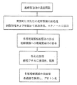
図5は、本発明の高分子電解質膜の製造工程の一例を示したフロート図である。以下に五工程からなる本発明の高分子電解質膜の製造工程を説明する。
【0032】
第一の工程では、高分子電解質溶液の濃度を調製した。市販の5wt%ナフィオン溶液をサンプル瓶に取り、攪拌しながら60度に加熱して溶液を13wt%まで濃縮した。
【0033】
第二の工程では、高分子電解質膜に前処理を施した。市販のナフィオン115膜を精製水で3回洗浄した後、脱脂処理として3%過酸化水素水で1時間煮沸してから再び精製水で3回洗浄し、さらに、精製水で1時間煮沸から室温の精製水に移して高分子電解質膜に十分に含水させた。つぎに、この高分子電解質膜をエタノールに10分間浸漬してナフィオン115膜を十分に膨潤させた。
【0034】
第三の工程では、高分子電解質膜前駆体を形成した。前処理を施した高分子電解質膜をエタノール中から取り出し、ろ紙を用いて膨潤状態の高分子電解質膜の表面に存在する余剰のエタノールを拭き取った後、高分子電解質膜が乾燥しないように迅速に、およそ2.4mg/cm2の13wt%ナフィオン溶液をスプレーにより高分子電解質膜の両面に塗布して、高分子電解質膜前駆体を形成した。
【0035】
第四の工程では、高分子電解質膜前駆体を多孔化処理して多孔質高分子電解質層を形成した。作製した高分子電解質膜前駆体を酢酸ブチルに10分間浸漬した後、取り出して室温で酢酸ブチルを乾燥すると、高分子電解質膜の両面に塗布した13wt%ナフィオン溶液は、固化して三次元連通性の孔を有する多孔質高分子電解質層を形成した。
【0036】
第五の工程では、高分子電解質膜に前処理を施した。作製した高分子電解質膜を精製水で3回洗浄した後、0.5Mの希硫酸で1時間煮沸して電解質の対イオンをプロトン型に置換する処理を施し、精製水で5回洗浄して精製水中に保存した。
【0037】
このようにして作製した高分子電解質膜を本発明による高分子電解質膜Aとして、その表面を示す電子顕微鏡写真を図2に示す。
【0038】
さらに、本発明になる高分子電解質膜Aを備える固体高分子電解質型燃料電池を作製した。以下にその作製方法を示す。
【0039】
白金を30wt%担持したカーボン触媒2.6gに精製水45ml加え、次いで2−プロパノール45mlを徐々に拡散しながら加えて、白金担持カーボン触媒を水/2−プロパノール混合溶媒に分散し、さらに攪拌器を用いて30分間混合する。この混合物にPTFEのディスパージョン溶液(三井デュポンフロロケミカル社製、PTFE固形成分:60%)0.5mlを攪拌しながら徐々に加えて、添加後30分間攪拌した後、5wt%ナフィオン溶液(米国、アルドリッチ社製)17.5mlを攪拌しながら徐々に加えて、さらに30分間攪拌して触媒分散液を作製した。
【0040】
スプレーによりこの触媒分散液を直径3cmの円形状に高分子電解質膜Aの両面に塗布し、乾燥して高分子電解質膜の両面に触媒層を形成した。この触媒層の白金触媒の含有量が約0.5mg/cm2になるように触媒分散物を塗布した。
【0041】
このようにして両面に触媒層を形成した高分子電解質膜Aに、ガス拡散層として直径3cmに裁断した撥水性を有するカーボンペーパーを両側に配置して、加熱圧接(120kg/cm2、135℃、5分間)により一体に接合してガス拡散電極−電解質膜接合体Aを作製した。
【0042】
このようにして作製したガス拡散電極−電解質膜接合体Aを、ガス供給路が形成された金属製のセパレータで挟持して本発明の固体高分子電解質型燃料電池Aを構成した。
【0043】
この燃料電池をつぎの条件で作動させて、電流−電圧特性を測定した。燃料ガスには純水素を用いて60℃に設定したバブラー式の加湿器で加湿した後、利用率が70%になる流量で電池に供給した。酸化ガスには純酸素を用いて60℃に設定したバブラー式の加湿器で加湿した後、利用率が50%になる流量で電池に供給した。反応ガスは、それぞれ大気圧で供給した。電池には65℃のクーラントを循環して、電池温度を一定に保った。
【0044】
[実施例2]
実施例1と同様にして、市販のパーフロロスルホン酸樹脂の溶液である5wt%ナフィオン溶液から濃度が23wt%のナフィオン溶液を調製し、このナフィオン溶液を用いて、高分子電解質膜の両面に三次元連通性の孔を有する多孔質高分子電解質を備える本発明の電解質膜Bを作製した。この高分子電解質膜Bの表面性状を示す電子顕微鏡写真を図3に示す。
【0045】
実施例1で調製した触媒分散物を、直径3cmの円形状に高分子電解質膜Bの両面にスプレー塗布して触媒層を形成した。この触媒層の白金触媒含有量は約0.5mg/cm2とした。この触媒層を形成した高分子電解質膜Bにガス拡散層として撥水性を有するカーボンペーパーを両側に配置して加熱圧接(120kg/cm2、135℃、5分間)により一体に接合してガス拡散電極−電解質膜接合体Bを作製した。
【0046】
このガス拡散電極−電解質膜接合体Bを、ガス供給路が形成された金属製のセパレータで挟持して、本発明の固体高分子電解質型燃料電池Bを構成し、実施例1と同じ条件で作動させて電流−電圧特性を測定した。
【0047】
[比較例1]
2000#のサンディングペーパーを用いてナフィオン115膜の両面を粗化した後、3%濃度の過酸化水素水で1時間煮沸してから精製水で5回洗浄し、つぎに0.5Mの希硫酸で1時間煮沸してプロトン型に置換した後、精製水で5回洗浄し、表面を粗化した高分子電解質膜を作製した。これを高分子電解質膜Cとした。
【0048】
この高分子電解質膜Cを備える固体高分子電解質型燃料電池を作製した。実施例1で調製した触媒分散物を、直径3cmの円形状に高分子電解質膜Cの両面にスプレー塗布して触媒層を形成した。この触媒層の白金触媒含有量は約0.5mg/cm2とした。この触媒層を形成した高分子電解質膜Cに、ガス拡散層として直径3cmに裁断した撥水性を有するカーボンペーパーを両側に配置して加熱圧接(120kg/cm2、135℃、5分間)により一体に接合してガス拡散電極−電解質膜接合体Cを作製した。
【0049】
このガス拡散電極−電解質膜接合体Cをガス供給路が形成された金属製のセパレータで挟持して従来の固体高分子電解質型燃料電池Cを構成し、実施例1と同じ条件で作動させて電流−電圧特性を測定した。
【0050】
[比較例2]
ナフィオン115膜を3%濃度の過酸化水素水で1時間煮沸してから精製水で5回洗浄し、つぎに0.5Mの希硫酸で1時間煮沸してプロトン型に置換した後、精製水で5回洗浄した。通常の表面の高分子電解質膜を高分子電解質膜Dとした。
【0051】
この高分子電解質膜Dを備えた固体高分子電解質型燃料電池を作製した。実施例1で調製した触媒分散物を、直径3cmの円形状に高分子電解質膜Dの両面にスプレー塗布して触媒層を形成した。この触媒層の白金触媒の含有量が約0.5mg/cm2とした。この触媒層を形成した高分子電解質膜Dに、ガス拡散層として直径3cmに裁断した撥水性を有するカーボンペーパーを両側に配置して加熱圧接(120kg/cm2、135℃、5分間)により一体に接合してガス拡散電極−電解質膜接合体Dを作製した。
【0052】
このガス拡散電極−電解質膜接合体Dを、ガス供給路が形成された金属製のセパレータで挟持して、従来の固体高分子電解質型燃料電池Dを構成し、実施例1と同じ条件で作動させて電流−電圧特性を測定した。
【0053】
実施例1、2および比較例1、2で作製した固体高分子電解質型燃料電池A、B、CおよびDの電流−電圧特性を図6に示す。図6から明らかなように、サンディングにより表面を粗化した高分子電解質膜を備える固体高分子電解質型燃料電池Cは、表面が平滑な通常の高分子電解質膜を備える固体高分子電解質型燃料電池Dより、高い電流密度での電池電圧の低下が少なく、高出力であり、優れた特性を示した。
【0054】
一方、本発明の高分子電解質膜を備える固体高分子電解質型燃料電池AおよびBは、従来の公知の高分子電解質膜を備えた固体高分子電解質型燃料電池CおよびDよりさらに高出力で特性が向上することを示した。また、本発明の高分子電解質膜を備えた固体高分子電解質型燃料電池AとBにおいては、高分子電解質膜の表面に形成した三次元連通性の孔を有する多孔質電解質層の多孔度が大きく、その表面積が大きい高分子電解質膜Aを備える方が、より高出力であり優れた特性を示すことがわかった。固体高分子電解質型燃料電池AおよびBにおいては高分子電解質膜の表面は三次元連通性の孔を有する多孔性であるために、ガス拡散電極と触媒層との界面の接触面積が増大し、もって実質的な反応面積の増大することにより電池の特性が向上したものと考えられる。本発明の高分子電解質膜は固体高分子電解質型燃料電池の高出力化に効果があると結論される。
【0055】
[実施例3]
実施例1で作製した本発明の高分子電解質膜Aを備える直接メタノール型燃料電池を作製した。はじめに、精製水50mlに白金黒3gを分散させた後、5wt%ナフィオン溶液5.3mlを加えて30分間攪拌してインク状の触媒分散物を調製した。これを触媒分散物Pとする。つぎに、精製水50mlにPt−RuOx(Pt:Ru=1:1)3gを分散させた後、5wt%ナフィオン溶液12.5mlを加えて30分間攪拌してインク状の触媒分散物を調製した。これを触媒分散物Rとする。高分子電解質膜Aの一方の面に、スプレーにより直径3cmの円形状に触媒分散物Pを塗布して乾燥し、カソードの触媒層を形成した。白金量は、約2.5mg/cm2であった。
【0056】
この高分子電解質膜Aのもう一方の面に、スプレーにより直径3cmの円形状に触媒分散物Rを塗布して乾燥し、アノードの触媒層を形成した。白金量は、約2.0mg/cm2であった。このカソードとアノードとを形成した高分子電解質膜Aに、カーボンペーパーを両側に配置して加熱圧接(120kg/cm2、135℃、5分間)により一体に接合して、ガス拡散電極−電解質膜接合体Eを作製した。
【0057】
このようにして作製したガス拡散電極−電解質膜接合体Eを、ガス供給路が形成された金属製のセパレータで挟持して、本発明の直接メタノール型燃料電池Eを構成した。
【0058】
この燃料電池をつぎの条件で作動させて、電流−電圧特性を測定した。カソードに3気圧に加圧した酸素を供給し、アノードに2気圧に加圧した1Mのメタノール/水を供給した。電池には110℃のクーラントを循環して、電池温度を一定に保った。
【0059】
[比較例3]
比較例2で前処理を施した高分子電解質膜Dを備える直接メタノール型燃料電池を作製した。高分子電解質膜Dの一方の面に、スプレーにより直径3cmの円形状に実施例5で調製した触媒分散物Pを塗布して乾燥し、カソードの触媒層を形成した。白金量は、約2.5mg/cm2であった。この高分子電解質膜Dのもう一方の面に、スプレーにより直径3cmの円形状に実施例5で調製した触媒分散物Rを塗布して乾燥し、アノードの触媒層を形成した。白金量は、約2.0mg/cm2であった。このカソードとアノードとを形成した高分子電解質膜Dに、カーボンペーパーを両側に配置して、加熱圧接(120kg/cm2、135℃、5分間)により一体に接合して、ガス拡散電極−電解質膜接合体Fを構成した。
【0060】
このガス拡散電極−電解質膜接合体Fを、ガス供給路が形成された金属製のセパレータで挟持して、直接メタノール型燃料電池Fを作製し、実施例5と同じ条件で作動させて電流−電圧特性を測定した。
【0061】
実施例3および比較例3で作製した直接メタノール型燃料電池EおよびFの電流−電圧特性を図7に示す。図7から明らかであるように、本発明の高分子電解質膜を備える直接メタノール型燃料電池Eは、従来の公知の高分子電解質膜を備えた直接メタノール型燃料電池Fより高出力であり優れた特性を示した。本発明の高分子電解質膜を備える直接メタノール型燃料電池Eでは、高分子電解質膜の表面は三次元連通性の孔を有する多孔性であるために、カソードおよびアノードの触媒層との界面の接触面積が増大し、もって実質的な反応面積の増大することにより電池の特性が向上したものと考えられる。本発明の高分子電解質膜は、直接メタノール型燃料電池の高出力化に効果があることがわかる。
【0062】
【発明の効果】
本発明の燃料電池ガス拡散電極−電解質膜接合体では、高分子電解質膜と電極との界面の接触面積が増大して実質的な反応部分が増大する。もって、本発明の燃料電池ガス拡散電極−電解質膜接合体を用いた固体高分子電解質型燃料電池や直接メタノール型燃料電池の高出力密度化を達成できる。
【図面の簡単な説明】
【図1】本発明の三次元連通性の孔を有する多孔質高分子電解質層を備えた電解質膜の断面を示す模式図である。
【図2】本発明の三次元連通性の孔を有する多孔質高分子電解質層の表面性状を示す図(電子顕微鏡写真)である。
【図3】本発明の三次元連通性の孔を有する多孔質高分子電解質層の表面性状を示す図(電子顕微鏡写真)である。
【図4】本発明の三次元連通性の孔を有する多孔質高分子電解質層の表面の基本構造を示す模式図である。
【図5】本発明の三次元連通性の孔を有する多孔質高分子電解質層を備えた電解質膜の作製工程を示す図である。
【図6】本発明の電解質膜を備えた固体高分子電解質型燃料電池AとBおよび従来公知の電解質膜を備えた固体高分子電解質型燃料電池CとDの電流−電圧特性曲線を示す図である。
【図7】本発明の電解質膜を備えた直接メタノール型燃料電池Eおよび従来公知の電解質膜を備えた直接メタノール型燃料電池Fの電流−電圧特性曲線を示す図である。
【符号の説明】
1 高分子電解質膜
2 三次元連通性の孔を有する多孔質高分子電解質層
3 本発明の高分子電解質膜
4 三次元連通性の孔を有する多孔質高分子電解質層の電解質部分
5 三次元連通性の孔を有する多孔質高分子電解質層の空孔部分
6 三次元連通性の孔を有する多孔質高分子電解質層の空孔部分の開口径
7 三次元連通性の孔を有する多孔質高分子電解質層の電解質部分の径[0001]
BACKGROUND OF THE INVENTION
The present invention comprises an electrolyte membraneRuPolymer electrolyte fuel cellandDirect methanol fuel cellDiffusion electrode-electrolyte membrane assembly for fuel cell and manufacturing method thereofIt is about.
[0002]
[Prior art]
With electrolyte membraneFuel cellFor solid polymer electrolyte fuel cell, direct methanol fuelBatteries, etc.There is. theseFuel cellIsHigh molecularIt has a structure with a cathode on one side of the electrolyte membrane and an anode on the other side.High molecularThe electrolyte membrane and the cathode or anode may or may not be integrated with each other.
[0003]
A solid polymer electrolyte fuel cell is an electrochemical device that obtains electric power by supplying, for example, oxygen as an oxidant to a cathode and supplying hydrogen as a fuel to an anode to cause an electrochemical reaction. The cathode and anode consist of a catalyst layer and a gas diffusion layer, and the cathode and anode are joined to the electrolyte membrane such that the catalyst layer is in contact with the electrolyte membrane. This catalyst layer is formed by binding a catalyst body such as carbon powder carrying white metal metal catalyst particles or platinum group metal catalyst particles with a binder or the like. An electrolyte may be added to the catalyst layer. As the binder, a fluorine-based resin such as polytetrafluoroethylene (PTFE) is generally used. This fluorine-based resin is also a water repellent that imparts appropriate water repellency to the catalyst layer. As the gas diffusion layer, carbon paper imparted with water repellency is used.
[0004]
A direct methanol fuel cell is an electrochemical device that obtains electric power by supplying an oxidant, for example, oxygen to a cathode and a fuel, for example, a mixture of methanol and water to an anode to cause an electrochemical reaction. The cathode and the anode are formed by layering a catalyst body such as carbon powder carrying white metal catalyst particles or platinum group metal catalyst particles using a binder such as polytetrafluoroethylene. Bonded to each surface.
[0005]
In a fuel cell such as a solid polymer electrolyte fuel cell or a direct methanol fuel cell having an electrolyte membrane, the electrochemical reaction of the cathode reaction and the anode reaction proceeds at the interface between the cathode and anode electrodes and the electrolyte membrane. For this reason, in order to improve the efficiency of these fuel cells, it is required to increase the contact area of the interface between the electrode and the electrolyte membrane.
[0006]
For this purpose, there is a method of providing irregularities on the surface of the electrolyte membrane. For example, in JP-A-3-158486, a method using a roll having irregularities, in JP-A-4-16969, a method using sputtering, in JP-A-4-220957, a method using plasma etching, Japanese Patent Laid-Open No. 6-279600 proposes to provide unevenness on the surface of the electrolyte membrane by embedding a cloth and then peeling it off.
[0007]
OrThere is a method of increasing the contact area between the electrolyte membrane and the catalyst layer by providing holes on the surface of the electrolyte membrane. For example, in Japanese Patent Laid-Open No. 58-7432, a dispersion medium in which an electrolyte is dissolved is crystallized into small droplets and then removed. In Japanese Patent Laid-Open No. 62-146926, a method of removing particles after embedding, or Japanese Patent Application Laid-Open No. 5-19464 proposes a method of mixing a low molecular weight organic material and then removing it.
[0008]
[Problems to be solved by the invention]
In the method using a roll, the method using sputtering, the method using plasma etching, or the method using a cloth as described above, the treatment process for providing unevenness is complicated and inferior in productivity, or the formed unevenness is rough. There is a problem that it is insufficient to increase the contact area of the interface with the electrode.
[0009]
In addition, it is difficult to completely remove the dispersion medium, particles, or low molecular organic material by the method of forming pores by removing the crystallized dispersion medium, embedded particles, or mixed low molecular organic material. The residue isHigh molecularIt interferes with the contact between the electrolyte membrane and the electrode, causing a decrease in activity. Alternatively, these residuesHigh molecularThis hinders ion conduction between the electrolyte membrane and the electrode.
[0010]
Also, by heating and solvent treatment applied in the process of removing theseHigh molecularThere is a problem that the electrolyte is deteriorated and the ionic conductivity is lowered. With thisHigh molecularThere is also a problem that the performance of an electrochemical device using an electrolyte membrane is lowered.
[0011]
Therefore, the present invention solves the above-mentioned problems, and the object is as follows.High molecularWhile increasing the contact area of the interface between the electrolyte membrane and the electrode,High molecularNo decrease in ionic conductivity due to electrolyte degradationGas diffusion electrode-electrolyte membrane assembly for fuel cellIs to provide. In addition, it aims at providing the manufacturing method excellent in productivity.
[0012]
[Means for Solving the Problems]
Dissolved in a solvent containing alcoholPolymer showing proton conductivity in waterAfter adjusting the concentration of the electrolyte solution, the solution applied in a layer form on the substrate is dissolved by immersing it in an organic solvent having a polar group other than the alcoholic hydroxyl group.High molecularThe electrolyte is solidified to form a porous film having three-dimensionally communicating pores. Using this method,Polymer showing proton conductivity in waterA three-dimensional communicating hole is provided on at least one surface of the electrolyte membranePorous polymer electrolyte composed of a polymer that exhibits proton conductivity in a hydrous stateForming a layer,High molecularBy increasing the surface area of the electrolyte membrane,High molecularThe contact area between the electrolyte membrane and the electrode is increased to increase the substantial reaction area.
[0013]
Claim 1The invention ofPolymer exhibiting proton conductivity in water-containing state in fuel cell gas diffusion electrode-electrolyte membrane assemblyAt least one surface of the electrolyte membrane has a three-dimensional communication hole having a hole diameter of 0.1 to 10 μm.A porous polymer electrolyte layer made of a polymer exhibiting proton conductivity in a water-containing state is provided.
[0014]
Claim 2The invention ofThe method for producing a fuel cell gas diffusion electrode-electrolyte membrane assembly according to claim 1, wherein the polymer electrolyte membrane in a water-containing state is immersed in alcohol and taken out, on at least one surface of the polymer electrolyte membrane.For solvents containing alcoholThe polymerSolution in which electrolyte is dissolvedPaintAfter weaving, soak in an organic solvent with polar groups other than alcoholic hydroxyl groupsThe porous layer is formed on the polymer electrolyte membrane, and a catalyst layer is formed on both sides of the polymer electrolyte membrane. Formed and laminated gas diffusion layerIt is characterized byRu.
[0015]
The fuel cell gas diffusion electrode-electrolyte membrane assembly of the present invention is used for a fuel cell such as a solid polymer electrolyte fuel cell or a direct methanol fuel cell..
[0016]
DETAILED DESCRIPTION OF THE INVENTION
Of the present inventionHigh molecularThe manufacturing method of the electrolyte membrane will be specifically described. For solvents containing alcoholHigh molecularAs the solution in which the electrolyte is dissolved, for example, a 5 wt% Nafion solution (Aldrich, USA) which is a solution of a commercially available perfluorosulfonic acid resin can be used. Various concentrations of the Nafion solution are prepared by concentrating the solvent of the Nafion solution.
[0017]
Polymer showing proton conductivity in waterAs the electrolyte membrane, for example, a commercially available Nafion 115 membrane (made by DuPont, USA), which is a perfluorosulfonic acid resin membrane, can be used. The Nafion 115 membrane is a nonporous membrane. thisHigh molecularThe electrolyte membrane is boiled with purified water for 1 hour to make it water-containing, and then immersed in an alcohol such as ethanol.High molecularFurther swell the electrolyte membrane. This swollenHigh molecularRemove the electrolyte membrane from the alcohol and wipe off any excess alcohol on the membrane surface with a paper towel.High molecularApply Nafion solution with the above concentration to at least one side of the electrolyte membrane using spraying means.High molecularAfter forming the electrolyte membrane precursor, as an organic solvent having a polar group other than the alcoholic hydroxyl group, for example, butyl acetate described aboveHigh molecularThe electrolyte membrane precursor is immersed and left to stand. Then from butyl acetateHigh molecularWhen the electrolyte membrane precursor is removed and dried at room temperature,High molecularAt least one surface of the electrolyte membrane has a three-dimensional communication hole having a hole diameter of 0.1 to 10 μm.Porous polymer electrolyte composed of polymerLayer formedHigh molecularAn electrolyte membrane can be produced.
[0018]
For solvents containing alcoholHigh molecularAlthough a 5 wt% Nafion solution, which is a commercially available solution of perfluorosulfonic acid resin, has been described as the solution in which the electrolyte is dissolved, the present invention is not limited to this solution, and may be a solution of perfluorosulfonic acid resin. For example, a solution of other perfluorosulfonic acid resin such as Flemion (manufactured by Asahi Glass) can be used, and the concentration of this solution can be arbitrarily changed by a method such as dilution or concentration. Alcohol or water or theseofThe mixtureHigh molecularAdd to the electrolyte solution and dilute or heatHigh molecularThere is a method of concentrating by removing a part of the solvent of the electrolyte solution.
[0019]
High molecularAlthough explanation was given using Nafion 115 as the electrolyte membrane, other perfluorosulfonic acid membranes, perfluorocarboxylic acid membranes, etc.High molecularHydrocarbons such as electrolyte membranes or styrene vinyl benzene sulfonic acidHigh molecularAny membrane may be used as long as it is a polymer membrane that exhibits proton conductivity in a water-containing state, such as an electrolyte membrane.
[0020]
However, among these polymer films, fluorine-based films such as perfluorosulfonic acid film and perfluorocarboxylic acid film with excellent heat resistanceHigh molecularAn electrolyte membrane is preferred.
[0021]
High molecularTo electrolyte membraneHigh molecularApplication of the electrolyte solution includes, for example, a doctor blade method and a screen printing method other than spraying, and a conventionally known method can be used.
[0022]
Moisture contentHigh molecularAs the alcohol for wetting the electrolyte membrane, methanol, 1-propanol, 2-propanol, 1-butanol or 2-butanol having 4 or less carbon atoms can be used in addition to ethanol.
[0023]
The organic solvent having a polar group other than an alcoholic hydroxyl group is not limited to the above-mentioned butyl acetate, but an organic solvent having an alkoxycarbonyl group in the molecule and having 1 to 7 carbon atoms, such as formic acid. Propyl, butyl formate, isobutyl formate, ethyl acetate, propyl acetate, isopropyl acetate, allyl acetate, butyl acetate, isobutyl acetate, pentyl acetate, isopentyl acetate, methyl propionate, ethyl propionate, propyl propionate, methyl acrylate, Butyl acrylate, isobutyl acrylate, methyl butyrate, methyl isobutyrate, ethyl butyrate, ethyl isobutyrate, methyl methacrylate, propyl butyrate, isopropyl isobutyrate, 2-ethoxyethyl acetate, 2- (2 ethoxyethoxy) ethyl acetate, etc. Single or mixture, or ether in the molecule An organic solvent having a carbon chain of 3 to 5 carbon atoms, such as dipropyl ether, dibutyl ether, ethylene glycol dimethyl ether, ethylene glycol diethyl ether, tripropylene glycol monomethyl ether, tetrahydrofuran, etc. An organic solvent having a carbon chain of 4 to 8 carbon atoms having a carbonyl group, for example, methylbutylketone, methylisobutylketone, methylhexylketone, dipropylketone or the like alone or a mixture thereof, or carbon having an amino group in the molecule An organic solvent having 1 to 5 carbon atoms in the chain, for example, isopropylamine, isobutylamine, tertiary butylamine, isopentylamine, diethylamine, etc., alone or as a mixture, or a carbon chain having a carboxyl group in the molecule The organic solvent having a carbon number 1-6, for example, can be used propionic acid, valeric acid, caproic acid, alone or a mixture of such heptanoic acid, or those derived from these combinations.
[0024]
Made in this wayHigh molecularPorous having at least one surface of the electrolyte membrane having a three-dimensional communication hole having a pore diameter of 0.1 to 10 μmHigh molecularOf the present invention comprising an electrolyte layer.High molecularA schematic cross section of the electrolyte membrane is shown in FIG. In this figure, 1 is non-porousHigh molecularAn electrolyte membrane, 2 is a porous material having three-dimensionally communicating poresHigh molecularIt is an electrolyte layer. 3 of the present inventionHigh molecularElectrolyte membrane, non-porousHigh molecularPorous having electrolyte membrane 1 and three-dimensional communicating poresHigh molecularIt consists of an electrolyte layer 2. 4 is a porous material having three-dimensionally communicating pores.High molecularThe electrolyte part of the
[0025]
This figure shows the non-porousHigh molecularPorous having three-dimensionally communicating pores only on one side of the electrolyte membrane 1High molecularThe multilayer electrolyte membrane provided with the electrolyte layer 2 has been described.High molecularPorous having similar three-dimensional communicating pores on the other side of the electrolyte membrane 1High molecularA multilayer electrolyte membrane including the electrolyte layer 2 may be used.
[0026]
Become the present inventionHigh molecularPorous having three-dimensionally communicating pores of electrolyte membrane 3High molecularAn example of an electron micrograph of the surface of the electrolyte layer 2 is shown in FIGS. FIG. 4 shows a porous structure having three-dimensional communicating pores.High molecularIt is the schematic diagram which showed the basic structure of the surface of an electrolyte layer. In FIG. 4,
[0027]
FIG. 2 shows the present invention prepared using a 13 wt% Nafion solution.High molecularPorous on the surface of the electrolyte layer and having three-dimensionally communicating poresHigh molecularThe opening diameter of the pore portion of the electrolyte layer is 0.3 to 5.0 μm, the diameter of the electrolyte portion of the porous electrolyte layer having three-dimensionally communicating pores is 0.2 to 1.0 μm, and the porosity is 70%. is there. FIG. 3 shows a porous material having three-dimensionally communicating pores according to the present invention prepared using a 23 wt% Nafion solution.High molecularWith electrolyte layerHigh molecularPorous surface of electrolyte membrane with three-dimensional communicating poresHigh molecularThe pore diameter of the pore portion of the electrolyte layer is 0.2 to 0.5 μm, and the porous layer has three-dimensional communication holes.High molecularOf electrolyte layerHigh molecularThe diameter of the electrolyte part is 0.5 to 2.0 μm, and the porosity is 15%.
[0028]
Porous with three-dimensional communicating pores depending on the concentration of Nafion solutionHigh molecularPorous having three-dimensional communicating pores in the pore diameter of the electrolyte layer in the range of 0.1 to 10 μmHigh molecularOf electrolyte layerHigh molecularThe diameter of the electrolyte portion can be adjusted in the range of 0.1 to 30 μm, and the porosity can be adjusted in the range of 10 to 90%.High molecularPorous with three-dimensionally communicating pores formed on the surface of the electrolyte membraneHigh molecularThe thickness of the electrolyte layer can be adjusted in the range of 1 to 50 μm depending on the amount of Nafion solution to be applied.
[0029]
Become the present inventionHigh molecularThe electrolyte membrane is a porous material having three-dimensionally communicating pores having pore diameters in the range of 0.1 to 10 μm on at least one surface.High molecularHas an electrolyte layer,High molecularWhile increasing the contact area of the interface between the electrolyte membrane and the electrode, there is no mixing of impurities such as dispersion media or particles or low molecular organic materials.High molecularThere is no decrease in proton conductivity because no treatment such as heating that causes deterioration of the electrolyte is performed. Therefore,High molecularIt is possible to increase the proton conductivity of the electrolyte membrane.High molecularBy using an electrolyte membrane, for example, a solid polymer electrolyte fuel cellAndDirect methanol fuel cell, etc.PolymerThe reaction at the interface between the electrolyte membrane and the electrode is involvedFuel cellCan be made high performance.
[0030]
【Example】
Next, a preferred embodiment of the present invention will be described with reference to the drawings.
[0031]
[Example 1]
FIG. 5 illustrates the present invention.High molecularIt is the float figure which showed an example of the manufacturing process of an electrolyte membrane. The present invention consists of the following five steps.High molecularThe manufacturing process of the electrolyte membrane will be described.
[0032]
In the first step,High molecularThe concentration of the electrolyte solution was prepared. A commercially available 5 wt% Nafion solution was taken in a sample bottle and heated to 60 degrees with stirring to concentrate the solution to 13 wt%.
[0033]
In the second step,High molecularThe electrolyte membrane was pretreated. A commercially available Nafion 115 membrane was washed 3 times with purified water, then boiled with 3% hydrogen peroxide for 1 hour as a degreasing treatment, washed again with purified water 3 times, and further boiled with purified water for 1 hour to room temperature. Transfer to purified waterHigh molecularThe electrolyte membrane was sufficiently hydrated. Then thisHigh molecularThe electrolyte membrane was immersed in ethanol for 10 minutes to sufficiently swell the Nafion 115 membrane.
[0034]
In the third step,High molecularAn electrolyte membrane precursor was formed. Pre-treatedHigh molecularRemove the electrolyte membrane from ethanol and use filter paper to swell the electrolyte membrane.High molecularAfter wiping off excess ethanol present on the surface of the electrolyte membrane,High molecularRapidly about 2.4 mg / cm so that the electrolyte membrane does not dry out2Spray 13wt% Nafion solutionHigh molecularApply to both sides of the electrolyte membrane,High molecularAn electrolyte membrane precursor was formed.
[0035]
In the fourth step,High molecularPorous electrolyte membrane precursorHigh molecularAn electrolyte layer was formed. MadeHigh molecularAfter immersing the electrolyte membrane precursor in butyl acetate for 10 minutes, taking out and drying butyl acetate at room temperature,High molecularThe 13 wt% Nafion solution applied on both sides of the electrolyte membrane is a porous solidified solid with three-dimensionally communicating pores.High molecularAn electrolyte layer was formed.
[0036]
In the fifth step,High molecularThe electrolyte membrane was pretreated. MadeHigh molecularThe electrolyte membrane is washed 3 times with purified water, then boiled with 0.5 M dilute sulfuric acid for 1 hour to replace the electrolyte counter ion with the proton type, washed with purified
[0037]
Made in this wayHigh molecularElectrolyte membrane according to the inventionHigh molecularAn electron micrograph showing the surface of the electrolyte membrane A is shown in FIG.
[0038]
Furthermore, it becomes this inventionHigh molecularA solid polymer electrolyte fuel cell including the electrolyte membrane A was produced. The manufacturing method is shown below.
[0039]
45 ml of purified water was added to 2.6 g of a carbon catalyst supporting 30 wt% of platinum, and then 45 ml of 2-propanol was added while gradually diffusing, to disperse the platinum-supported carbon catalyst in a water / 2-propanol mixed solvent, and a stirrer For 30 minutes. To this mixture, 0.5 ml of a PTFE dispersion solution (Mitsui Dupont Fluoro Chemical Co., Ltd., PTFE solid component: 60%) was gradually added with stirring. After the addition, the mixture was stirred for 30 minutes. 17.5 ml) (Aldrich) was gradually added with stirring, and further stirred for 30 minutes to prepare a catalyst dispersion.
[0040]
Spray this catalyst dispersion into a 3cm diameter circleHigh molecularApply to both sides of electrolyte membrane A and dryHigh molecularCatalyst layers were formed on both sides of the electrolyte membrane. The platinum catalyst content of this catalyst layer is about 0.5 mg / cm2The catalyst dispersion was applied so that
[0041]
In this way, a catalyst layer was formed on both sides.High molecularA carbon paper having water repellency cut into a diameter of 3 cm as a gas diffusion layer is disposed on both sides of the electrolyte membrane A, and heated and pressed (120 kg / cm2The gas diffusion electrode-electrolyte membrane assembly A was manufactured by integrally bonding at 135 ° C. for 5 minutes.
[0042]
The gas diffusion electrode-electrolyte membrane assembly A thus produced was sandwiched by a metal separator having a gas supply path to constitute a solid polymer electrolyte fuel cell A of the present invention.
[0043]
The fuel cell was operated under the following conditions, and current-voltage characteristics were measured. The fuel gas was humidified with a bubbler type humidifier set to 60 ° C. using pure hydrogen, and then supplied to the battery at a flow rate at which the utilization rate became 70%. The oxidizing gas was humidified with a bubbler type humidifier set to 60 ° C. using pure oxygen, and then supplied to the battery at a flow rate at which the utilization rate was 50%. Each reaction gas was supplied at atmospheric pressure. A 65 ° C. coolant was circulated through the battery to keep the battery temperature constant.
[0044]
[Example 2]
In the same manner as in Example 1, a Nafion solution having a concentration of 23 wt% was prepared from a 5 wt% Nafion solution, which is a commercially available perfluorosulfonic acid resin solution, and this Nafion solution was used.High molecularPorous with three-dimensional communicating pores on both sides of electrolyte membraneHigh molecularAn electrolyte membrane B of the present invention including an electrolyte was produced. thisHigh molecularAn electron micrograph showing the surface properties of the electrolyte membrane B is shown in FIG.
[0045]
The catalyst dispersion prepared in Example 1 was formed into a circular shape having a diameter of 3 cm.High molecularA catalyst layer was formed by spray coating on both surfaces of the electrolyte membrane B. The platinum catalyst content of this catalyst layer is about 0.5 mg / cm.2It was. This catalyst layer was formedHigh molecularCarbon paper having water repellency as a gas diffusion layer is disposed on both sides of the electrolyte membrane B, and heated and pressed (120 kg / cm2The gas diffusion electrode-electrolyte membrane assembly B was manufactured by integrally bonding at 135 ° C. for 5 minutes.
[0046]
The gas diffusion electrode-electrolyte membrane assembly B is sandwiched between metal separators having gas supply passages to form a solid polymer electrolyte fuel cell B of the present invention, under the same conditions as in Example 1. The current-voltage characteristic was measured by operating.
[0047]
[Comparative Example 1]
After roughening both sides of Nafion 115 membrane using 2000 # sanding paper, boil it in 3% hydrogen peroxide solution for 1 hour, then wash it with
[0048]
thisHigh molecularA solid polymer electrolyte fuel cell including the electrolyte membrane C was produced. The catalyst dispersion prepared in Example 1 was formed into a circular shape having a diameter of 3 cm.High molecularA catalyst layer was formed by spray coating on both surfaces of the electrolyte membrane C. The platinum catalyst content of this catalyst layer is about 0.5 mg / cm.2It was. This catalyst layer was formedHigh molecularA carbon paper having water repellency cut to a diameter of 3 cm as a gas diffusion layer is arranged on both sides of the electrolyte membrane C and heated and pressed (120 kg / cm2The gas diffusion electrode-electrolyte membrane assembly C was manufactured by integrally bonding at 135 ° C. for 5 minutes.
[0049]
The gas diffusion electrode-electrolyte membrane assembly C is sandwiched between metal separators having gas supply paths to form a conventional solid polymer electrolyte fuel cell C, which is operated under the same conditions as in Example 1. Current-voltage characteristics were measured.
[0050]
[Comparative Example 2]
The Nafion 115 membrane is boiled with 3% hydrogen peroxide solution for 1 hour, washed 5 times with purified water, then boiled with 0.5 M dilute sulfuric acid for 1 hour to replace the proton type, and then purified water. And washed 5 times. Normal surfaceHigh molecularElectrolyte membraneHigh molecularAn electrolyte membrane D was obtained.
[0051]
thisHigh molecularA solid polymer electrolyte fuel cell provided with the electrolyte membrane D was produced. The catalyst dispersion prepared in Example 1 was formed into a circular shape having a diameter of 3 cm.High molecularA catalyst layer was formed by spray coating on both surfaces of the electrolyte membrane D. The platinum catalyst content of this catalyst layer is about 0.5 mg / cm2It was. This catalyst layer was formedHigh molecularA carbon paper having water repellency cut to a diameter of 3 cm as a gas diffusion layer is arranged on both sides of the electrolyte membrane D and heated and pressed (120 kg / cm2The gas diffusion electrode-electrolyte membrane assembly D was manufactured by integrally bonding at 135 ° C. for 5 minutes.
[0052]
The gas diffusion electrode-electrolyte membrane assembly D is sandwiched between metal separators having gas supply paths to form a conventional solid polymer electrolyte fuel cell D, which operates under the same conditions as in Example 1. The current-voltage characteristics were measured.
[0053]
Example 12 and Comparative Examples 1 and 2FIG. 6 shows the current-voltage characteristics of the solid polymer electrolyte fuel cells A, B, C and D produced in the above. As is apparent from FIG. 6, the surface was roughened by sanding.High molecularThe solid polymer electrolyte fuel cell C provided with an electrolyte membrane is a normal surface with a smooth surface.High molecularCompared with the solid polymer electrolyte fuel cell D provided with an electrolyte membrane, the battery voltage was not decreased much at a high current density, and the output was high, and excellent characteristics were exhibited.
[0054]
On the other hand, the present inventionHigh molecularSolid polymer electrolyte fuel cells A and B having an electrolyte membrane are known in the art.High molecularIt was shown that the characteristics were improved at higher output than the solid polymer electrolyte fuel cells C and D having the electrolyte membrane. In addition, the present inventionHigh molecularIn the solid polymer electrolyte fuel cells A and B having the electrolyte membrane,High molecularPorous electrolyte layer with three-dimensionally communicating pores formed on the surface of the electrolyte membrane has a large porosity and a large surface areaHigh molecularIt was found that the one provided with the electrolyte membrane A has higher output and excellent characteristics.Polymers in solid polymer electrolyte fuel cells A and BSince the surface of the electrolyte membrane is porous with three-dimensionally communicating pores, the contact area at the interface between the gas diffusion electrode and the catalyst layer is increased, thereby increasing the substantial reaction area and thus the battery characteristics Is considered to have improved. Of the present inventionHigh molecularIt is concluded that the electrolyte membrane is effective in increasing the output of the solid polymer electrolyte fuel cell.
[0055]
[Example3]
Example 1 of the present invention produced in Example 1High molecularA direct methanol fuel cell including the electrolyte membrane A was produced. First, 3 g of platinum black was dispersed in 50 ml of purified water, and 5.3 ml of 5 wt% Nafion solution was added and stirred for 30 minutes to prepare an ink-like catalyst dispersion. This is referred to as catalyst dispersion P. Next, 3 g of Pt—RuOx (Pt: Ru = 1: 1) was dispersed in 50 ml of purified water, and then 12.5 ml of 5 wt% Nafion solution was added and stirred for 30 minutes to prepare an ink-like catalyst dispersion. . This is referred to as catalyst dispersion R.High molecularThe catalyst dispersion P was applied to one surface of the electrolyte membrane A in a circular shape having a diameter of 3 cm by spraying and dried to form a cathode catalyst layer. The amount of platinum is about 2.5 mg / cm2Met.
[0056]
thisHigh molecularThe catalyst dispersion R was applied to the other surface of the electrolyte membrane A in a circular shape with a diameter of 3 cm by spraying and dried to form an anode catalyst layer. The amount of platinum is about 2.0 mg / cm2Met. Formed this cathode and anodeHigh molecularOn the electrolyte membrane A, carbon paper is arranged on both sides and heated and pressed (120 kg / cm2The gas diffusion electrode-electrolyte membrane assembly E was manufactured by integrally bonding at 135 ° C. for 5 minutes.
[0057]
The direct diffusion fuel cell E of the present invention was configured by sandwiching the gas diffusion electrode-electrolyte membrane assembly E thus produced with a metal separator having a gas supply path.
[0058]
The fuel cell was operated under the following conditions, and current-voltage characteristics were measured. Oxygen pressurized to 3 atmospheres was supplied to the cathode, and 1M methanol / water pressurized to 2 atmospheres was supplied to the anode. A 110 ° C. coolant was circulated through the battery to keep the battery temperature constant.
[0059]
[Comparative Example 3]
Pretreatment was performed in Comparative Example 2.High molecularA direct methanol fuel cell including the electrolyte membrane D was produced.High molecularOn one surface of the electrolyte membrane D, the catalyst dispersion P prepared in Example 5 was applied in a circular shape with a diameter of 3 cm by spraying and dried to form a cathode catalyst layer. The amount of platinum is about 2.5 mg / cm2Met. thisHigh molecularOn the other surface of the electrolyte membrane D, the catalyst dispersion R prepared in Example 5 was applied in a circular shape with a diameter of 3 cm by spraying and dried to form an anode catalyst layer. The amount of platinum is about 2.0 mg / cm2Met. Formed this cathode and anodeHigh molecularCarbon paper is placed on both sides of the electrolyte membrane D, and heated pressure welding (120 kg / cm2, 135 ° C., 5 minutes) to form a gas diffusion electrode-electrolyte membrane assembly F.
[0060]
The gas diffusion electrode-electrolyte membrane assembly F is sandwiched between metal separators having a gas supply path to produce a direct methanol fuel cell F, which is operated under the same conditions as in Example 5 to produce current- Voltage characteristics were measured.
[0061]
Example3andComparative Example 3FIG. 7 shows the current-voltage characteristics of the direct methanol fuel cells E and F produced in the above. As is clear from FIG.High molecularA direct methanol fuel cell E provided with an electrolyte membrane is known in the art.High molecularThe output was higher than that of the direct methanol fuel cell F provided with the electrolyte membrane, and excellent characteristics were exhibited.In the direct methanol fuel cell E having the polymer electrolyte membrane of the present invention, the polymerSince the surface of the electrolyte membrane is porous with three-dimensionally communicating pores, the contact area of the interface between the cathode and the anode catalyst layer is increased, thereby increasing the substantial reaction area and thus the battery characteristics. Is considered to have improved. Of the present inventionHigh molecularIt can be seen that the electrolyte membrane is effective in increasing the output of the direct methanol fuel cell.
[0062]
【The invention's effect】
In the fuel cell gas diffusion electrode-electrolyte membrane assembly of the present invention, the contact area at the interface between the polymer electrolyte membrane and the electrode increases, and the substantial reaction portion increases. Accordingly, it is possible to achieve a high output density of a solid polymer electrolyte fuel cell or a direct methanol fuel cell using the fuel cell gas diffusion electrode-electrolyte membrane assembly of the present invention.
[Brief description of the drawings]
FIG. 1 shows a porous structure having three-dimensional communicating pores according to the present invention.High molecularIt is a schematic diagram which shows the cross section of the electrolyte membrane provided with the electrolyte layer.
FIG. 2 shows a porous body having three-dimensional communicating pores according to the present invention.High molecularIt is a figure (electron micrograph) which shows the surface property of an electrolyte layer.
FIG. 3 shows a porous body having three-dimensional communicating pores according to the present invention.High molecularIt is a figure (electron micrograph) which shows the surface property of an electrolyte layer.
FIG. 4 shows a porous structure having three-dimensional communicating pores according to the present invention.High molecularIt is a schematic diagram which shows the basic structure of the surface of an electrolyte layer.
FIG. 5 is a porous view having three-dimensional communicating pores according to the present invention.High molecularIt is a figure which shows the preparation processes of the electrolyte membrane provided with the electrolyte layer.
FIG. 6 is a graph showing current-voltage characteristic curves of solid polymer electrolyte fuel cells A and B equipped with the electrolyte membrane of the present invention and solid polymer electrolyte fuel cells C and D equipped with conventionally known electrolyte membranes. It is.
FIG. 7 is a diagram showing current-voltage characteristic curves of a direct methanol fuel cell E equipped with the electrolyte membrane of the present invention and a direct methanol fuel cell F equipped with a conventionally known electrolyte membrane.
[Explanation of symbols]
1High molecularElectrolyte membrane
2 Porous with three-dimensional communicating poresHigh molecularElectrolyte layer
3 of the present inventionHigh molecularElectrolyte membrane
4 Porous with three-dimensional communicating poresHigh molecularElectrolyte part of electrolyte layer
5 Porous with three-dimensional communicating poresHigh molecularHole part of electrolyte layer
6 Porous with three-dimensional communicating poresHigh molecularOpening diameter of pore part of electrolyte layer
7 Porous with three-dimensional communicating poresHigh molecularDiameter of the electrolyte part of the electrolyte layer
Claims (2)
Priority Applications (3)
| Application Number | Priority Date | Filing Date | Title |
|---|---|---|---|
| JP23494698A JP3978757B2 (en) | 1998-08-05 | 1998-08-05 | Gas diffusion electrode-electrolyte membrane assembly for fuel cell and method for producing the same |
| US09/369,143 US6562446B1 (en) | 1998-08-05 | 1999-08-05 | Multi-layer polymer electrolyte-membrane, electrochemical apparatus and process for the preparation of multi-layer polymer electrolyte membrane |
| CNB991112830A CN1163998C (en) | 1998-08-05 | 1999-08-05 | Polymer dielectric membrne, electrochemical unit and manufacture of polymer dielectric membrane |
Applications Claiming Priority (1)
| Application Number | Priority Date | Filing Date | Title |
|---|---|---|---|
| JP23494698A JP3978757B2 (en) | 1998-08-05 | 1998-08-05 | Gas diffusion electrode-electrolyte membrane assembly for fuel cell and method for producing the same |
Publications (3)
| Publication Number | Publication Date |
|---|---|
| JP2000054176A JP2000054176A (en) | 2000-02-22 |
| JP2000054176A5 JP2000054176A5 (en) | 2005-10-27 |
| JP3978757B2 true JP3978757B2 (en) | 2007-09-19 |
Family
ID=16978748
Family Applications (1)
| Application Number | Title | Priority Date | Filing Date |
|---|---|---|---|
| JP23494698A Expired - Fee Related JP3978757B2 (en) | 1998-08-05 | 1998-08-05 | Gas diffusion electrode-electrolyte membrane assembly for fuel cell and method for producing the same |
Country Status (1)
| Country | Link |
|---|---|
| JP (1) | JP3978757B2 (en) |
Families Citing this family (8)
| Publication number | Priority date | Publication date | Assignee | Title |
|---|---|---|---|---|
| JP2004534907A (en) | 2001-03-12 | 2004-11-18 | ヘッカー,カール−ハインツ | Method and apparatus for generating oxygen |
| JP4529345B2 (en) * | 2002-07-31 | 2010-08-25 | 日産自動車株式会社 | Method for producing polymer electrolyte fuel cell |
| JP4476594B2 (en) | 2003-10-17 | 2010-06-09 | 淳二 城戸 | Organic electroluminescent device |
| JP2005302612A (en) * | 2004-04-14 | 2005-10-27 | Toyota Motor Corp | Solid electrolyte membrane |
| JP5283826B2 (en) * | 2005-03-02 | 2013-09-04 | キヤノン株式会社 | Membrane electrode assembly and polymer electrolyte fuel cell |
| KR100787865B1 (en) * | 2005-04-19 | 2007-12-27 | 한국과학기술연구원 | Polymer electrolyte membrane fuel cell having Nafion cast membrane where its thickness is limited and method for operating the same |
| US8642810B2 (en) * | 2009-07-10 | 2014-02-04 | Basf Se | Method for the direct amination of hydrocarbons into amino hydrocarbons, including electrochemical separation of hydrogen and electrochemical reaction of the hydrogen into water |
| CN111074296B (en) * | 2019-12-31 | 2021-07-09 | 山东东岳高分子材料有限公司 | Air bubble dispersing coating with ion conduction function and preparation method thereof |
-
1998
- 1998-08-05 JP JP23494698A patent/JP3978757B2/en not_active Expired - Fee Related
Also Published As
| Publication number | Publication date |
|---|---|
| JP2000054176A (en) | 2000-02-22 |
Similar Documents
| Publication | Publication Date | Title |
|---|---|---|
| US10454122B2 (en) | Reinforced electrode assembly | |
| JP3866077B2 (en) | Method for preparing a membrane electrode assembly | |
| US6562446B1 (en) | Multi-layer polymer electrolyte-membrane, electrochemical apparatus and process for the preparation of multi-layer polymer electrolyte membrane | |
| JP4144686B2 (en) | Method for producing polymer electrolyte fuel cell | |
| US20020019308A1 (en) | Composite catalyst for solid polymer electrolyte type fuel cell and processes for producing the same | |
| US6391487B1 (en) | Gas diffusion electrode, method for manufacturing the same, and fuel cell with such electrode | |
| WO2013064640A1 (en) | Method for the preparation of catalyst-coated membranes | |
| US20110097651A1 (en) | Membrane Electrode Assembly (MEA) Fabrication Procedure on Polymer Electrolyte Membrane Fuel Cell | |
| JP5532630B2 (en) | Membrane electrode assembly, method for producing the same, and polymer electrolyte fuel cell | |
| JP2010505222A (en) | Structure for gas diffusion electrode | |
| US8715878B2 (en) | Polymer electrolyte fuel cell, membrane electrode assembly and manufacturing method thereof | |
| JP2008521168A (en) | Preconditioning of fuel cell membrane electrode assembly | |
| JP3978757B2 (en) | Gas diffusion electrode-electrolyte membrane assembly for fuel cell and method for producing the same | |
| JP2005108770A (en) | Manufacturing method of electrolyte membrane electrode joint body | |
| JP4576813B2 (en) | Polymer electrolyte membrane and membrane electrode assembly | |
| JP2000299119A (en) | Manufacture of catalyst layer | |
| JP3965666B2 (en) | Gas diffusion electrode and manufacturing method thereof | |
| JP4117430B2 (en) | Gas diffusion electrode and fuel cell having the same | |
| JP4403634B2 (en) | Composite catalyst for solid polymer electrolyte fuel cell. | |
| JP5326458B2 (en) | Membrane electrode assembly, method for producing the same, and polymer electrolyte fuel cell | |
| JP4045661B2 (en) | ELECTROLYTE MEMBRANE, PROCESS FOR PRODUCING THE SAME, AND SOLID POLYMER ELECTROLYTE FUEL CELL USING THE SAME | |
| JP5634013B2 (en) | Method for producing catalyst layer for fuel cell, catalyst layer transfer sheet, and catalyst layer-electrolyte membrane laminate | |
| JP4893704B2 (en) | Method for producing catalyst layer for polymer electrolyte fuel cell and catalyst layer-electrolyte membrane laminate | |
| JP2010033897A (en) | Method of manufacturing catalyst layer of solid polymer fuel cell, and catalyst layer-electrolyte film laminate | |
| JP5369580B2 (en) | Membrane electrode assembly, method for producing the same, and polymer electrolyte fuel cell |
Legal Events
| Date | Code | Title | Description |
|---|---|---|---|
| A521 | Written amendment |
Free format text: JAPANESE INTERMEDIATE CODE: A523 Effective date: 20050802 |
|
| A621 | Written request for application examination |
Free format text: JAPANESE INTERMEDIATE CODE: A621 Effective date: 20050802 |
|
| A711 | Notification of change in applicant |
Free format text: JAPANESE INTERMEDIATE CODE: A712 Effective date: 20051213 |
|
| A977 | Report on retrieval |
Free format text: JAPANESE INTERMEDIATE CODE: A971007 Effective date: 20060928 |
|
| A131 | Notification of reasons for refusal |
Free format text: JAPANESE INTERMEDIATE CODE: A131 Effective date: 20061003 |
|
| A521 | Written amendment |
Free format text: JAPANESE INTERMEDIATE CODE: A523 Effective date: 20061201 |
|
| TRDD | Decision of grant or rejection written | ||
| A01 | Written decision to grant a patent or to grant a registration (utility model) |
Free format text: JAPANESE INTERMEDIATE CODE: A01 Effective date: 20070604 |
|
| A61 | First payment of annual fees (during grant procedure) |
Free format text: JAPANESE INTERMEDIATE CODE: A61 Effective date: 20070617 |
|
| R150 | Certificate of patent or registration of utility model |
Free format text: JAPANESE INTERMEDIATE CODE: R150 |
|
| FPAY | Renewal fee payment (event date is renewal date of database) |
Free format text: PAYMENT UNTIL: 20100706 Year of fee payment: 3 |
|
| FPAY | Renewal fee payment (event date is renewal date of database) |
Free format text: PAYMENT UNTIL: 20100706 Year of fee payment: 3 |
|
| FPAY | Renewal fee payment (event date is renewal date of database) |
Free format text: PAYMENT UNTIL: 20110706 Year of fee payment: 4 |
|
| FPAY | Renewal fee payment (event date is renewal date of database) |
Free format text: PAYMENT UNTIL: 20110706 Year of fee payment: 4 |
|
| S111 | Request for change of ownership or part of ownership |
Free format text: JAPANESE INTERMEDIATE CODE: R313111 |
|
| FPAY | Renewal fee payment (event date is renewal date of database) |
Free format text: PAYMENT UNTIL: 20110706 Year of fee payment: 4 |
|
| R360 | Written notification for declining of transfer of rights |
Free format text: JAPANESE INTERMEDIATE CODE: R360 |
|
| FPAY | Renewal fee payment (event date is renewal date of database) |
Free format text: PAYMENT UNTIL: 20110706 Year of fee payment: 4 |
|
| R360 | Written notification for declining of transfer of rights |
Free format text: JAPANESE INTERMEDIATE CODE: R360 |
|
| R371 | Transfer withdrawn |
Free format text: JAPANESE INTERMEDIATE CODE: R371 |
|
| S111 | Request for change of ownership or part of ownership |
Free format text: JAPANESE INTERMEDIATE CODE: R313111 |
|
| FPAY | Renewal fee payment (event date is renewal date of database) |
Free format text: PAYMENT UNTIL: 20110706 Year of fee payment: 4 |
|
| R350 | Written notification of registration of transfer |
Free format text: JAPANESE INTERMEDIATE CODE: R350 |
|
| FPAY | Renewal fee payment (event date is renewal date of database) |
Free format text: PAYMENT UNTIL: 20110706 Year of fee payment: 4 |
|
| FPAY | Renewal fee payment (event date is renewal date of database) |
Free format text: PAYMENT UNTIL: 20120706 Year of fee payment: 5 |
|
| FPAY | Renewal fee payment (event date is renewal date of database) |
Free format text: PAYMENT UNTIL: 20130706 Year of fee payment: 6 |
|
| LAPS | Cancellation because of no payment of annual fees |