JP3977258B2 - Closure unit for nozzle strips on the nozzle beam that hydrodynamically entangles the fibers of the product web - Google Patents
Closure unit for nozzle strips on the nozzle beam that hydrodynamically entangles the fibers of the product web Download PDFInfo
- Publication number
- JP3977258B2 JP3977258B2 JP2002564176A JP2002564176A JP3977258B2 JP 3977258 B2 JP3977258 B2 JP 3977258B2 JP 2002564176 A JP2002564176 A JP 2002564176A JP 2002564176 A JP2002564176 A JP 2002564176A JP 3977258 B2 JP3977258 B2 JP 3977258B2
- Authority
- JP
- Japan
- Prior art keywords
- nozzle
- nozzle beam
- strip
- plug
- slit
- Prior art date
- Legal status (The legal status is an assumption and is not a legal conclusion. Google has not performed a legal analysis and makes no representation as to the accuracy of the status listed.)
- Expired - Lifetime
Links
- 239000000835 fiber Substances 0.000 title claims description 5
- 238000003780 insertion Methods 0.000 claims description 13
- 230000037431 insertion Effects 0.000 claims description 13
- 239000002184 metal Substances 0.000 claims description 13
- 229910052751 metal Inorganic materials 0.000 claims description 13
- 239000007788 liquid Substances 0.000 claims description 12
- 239000004744 fabric Substances 0.000 claims description 5
- 239000002759 woven fabric Substances 0.000 claims description 2
- 239000004753 textile Substances 0.000 claims 1
- 230000007704 transition Effects 0.000 claims 1
- XLYOFNOQVPJJNP-UHFFFAOYSA-N water Substances O XLYOFNOQVPJJNP-UHFFFAOYSA-N 0.000 description 8
- 238000000034 method Methods 0.000 description 2
- 238000007789 sealing Methods 0.000 description 2
- 239000004020 conductor Substances 0.000 description 1
- 230000008878 coupling Effects 0.000 description 1
- 238000010168 coupling process Methods 0.000 description 1
- 238000005859 coupling reaction Methods 0.000 description 1
- 150000002739 metals Chemical class 0.000 description 1
- 230000000149 penetrating effect Effects 0.000 description 1
Images


Classifications
-
- D—TEXTILES; PAPER
- D04—BRAIDING; LACE-MAKING; KNITTING; TRIMMINGS; NON-WOVEN FABRICS
- D04H—MAKING TEXTILE FABRICS, e.g. FROM FIBRES OR FILAMENTARY MATERIAL; FABRICS MADE BY SUCH PROCESSES OR APPARATUS, e.g. FELTS, NON-WOVEN FABRICS; COTTON-WOOL; WADDING ; NON-WOVEN FABRICS FROM STAPLE FIBRES, FILAMENTS OR YARNS, BONDED WITH AT LEAST ONE WEB-LIKE MATERIAL DURING THEIR CONSOLIDATION
- D04H18/00—Needling machines
- D04H18/04—Needling machines with water jets
-
- D—TEXTILES; PAPER
- D06—TREATMENT OF TEXTILES OR THE LIKE; LAUNDERING; FLEXIBLE MATERIALS NOT OTHERWISE PROVIDED FOR
- D06C—FINISHING, DRESSING, TENTERING OR STRETCHING TEXTILE FABRICS
- D06C29/00—Finishing or dressing, of textile fabrics, not provided for in the preceding groups
Description
【0001】
本発明は、繊維ウェブ(Faserbahn)、薄織物(Tissue)等、織物(Gewebe)または編み物(Gewirke)のような、ビームに沿って案内されたウェブの繊維をハイドロダイナミックに噴流負荷するための極微細な液体噴流を発生する装置に設けられたノズルビームであって、該ノズルビームが、ウェブの働き巾にわたって延在する上側の部分と下側の部分とから成っており、上側の部分にはその全長にわたって、横断面で見て円形の圧力室が配置されており、該圧力室に、圧力下にある液体が例えば端面側で供給されており、前記圧力室に対して平行に下側の部分内に圧力分配室が設けられており、該圧力分配室が、圧力分配室の横断面に比して狭幅の液体流出スリットへと移行し、該液体流出スリットの上部に、ノズルストリップが液密にノズルビーム内に支承されており、前記ノズルストリップが、ノズルビームの端面に設けられた閉鎖可能な開口を介して交換可能である形式のものに関する。
【0002】
この種の装置はドイツ連邦共和国特許出願公開第19501738号明細書に開示されており、その内容を図面と共に背景技術としてここで少し説明する。圧力室内には1000バールまでの水圧が形成され、この水圧は当然ノズルビームの端面側の壁にも作用する。孔をビーム内に製作するために、一方の端面は当初開いていなければならないが、その後で、カバーにより閉鎖されなければならない。圧力室のために、かつ圧力分配室のためにも、独自のカバーが設けられており、これらのカバーはねじによりノズルビーム壁に固定されている。ノズルストリップ交換開口を閉鎖するために同じく独自のカバーが設けられており、このカバーもねじでノズルビーム壁に保持されている。液密にシールするために、その都度、シールしたい壁中に填め込まれた丸ヒモリングが働く。
【0003】
場合によっては必要なノズルストリップの交換のためには、水供給の停止後に、そこに設けられていてカバーをビームに固定している両ねじが、スパナもしくはレンチを用いて解離されなければならないし、再使用のためにはカバーがねじにより両側で固定されなければならない。確かにたった2本のねじを解離すればよいことではあるが、このためにはスパナが必要であって、このことは欠点として見なされることができる。
【0004】
本発明の課題は、冒頭に記載した形式のノズルビームを改良して、機械的な分解なしに、つまりスパナを必要とせずに、ノズルストリップの迅速交換を可能にする解決策を提供することである。
【0005】
上記の課題は、閉鎖可能な開口に閉鎖ユニットが設けられており、該閉鎖ユニットには、ノズルストリップ支承箇所の高さに、ノズルストリップのための差込スリットが設けられており、該差込スリットが差込栓により閉鎖可能であることにより解決される。
【0006】
差込栓は、閉鎖ユニットに固定されたピンにより保持されていることができる。このピンは水供給の停止後、つまり水圧の停止後に容易に、差込栓をノズルビームに固定する孔から引き抜かれることができる。ピンの紛失は、ピンをノズルビームに例えば糸状の結合手段を介して確保することにより回避され得る。差込栓は手で閉鎖ユニットから、有利にはノズルストリップと一緒に引き抜かれることができ、その後でノズルストリップは再度、新しいストリップに交換された後に、差込栓と共に差し込まれることができる。
【0007】
以下に図面を参照しながら本発明の実施例について詳説する。
【0008】
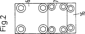
図1〜図3から見て取れるノズルビームは、ドイツ連邦共和国特許出願公開第19501738号明細書より公知である。このノズルビームは別の、但し原理的には類似したノズルビームによりここでは代用されていてよい。ノズルビームのハウジングは上側部分1から成っており、上側部分1は下側部分2に、全長にわたって幾重にもねじ(図示せず)により下方から螺設されている。上側部分1は長手方向で2つの孔4,5を有しており、そのうちの上側の孔4は圧力室4であり、下側の孔5は圧力分配室5である。両方の室は一方の端面で開いており、再度カバー6,7により液密に螺設されている。他方の端面で圧力室4は開口4′を有しており、この開口4′を通して、圧力下に置かれた液体が導入される。両方の室4,5は中間壁8により互いに隔離されている。ノズルビームの長さにわたって、中間壁8内に設けられた多数の貫流孔9が両方の室を接続しているので、圧力室4内に流入した液体は長手方向にわたって均等に分配されて圧力分配室5へと流出する。圧力分配室は下方に向かって開いており、要するに、圧力分配室5の孔の直径に比して狭幅なスリット10により開いており、このスリット10は同じくビームの全長にわたって延びている。
【0009】
上側部分1は下側部分2に固定的にかつ液密に螺設されている。シール性はOリング11により生ぜしめられ、Oリング11は上側部分1の環状溝11′内に封入されている。Oリング11の間の中央でスリット10をばね突出部23が包囲しており、このばね突出部23は、下側部分2の対応する溝25内に圧入されている。さらに、下側部分2の溝25の底部には環状溝12′が加工成形されており、この環状溝12′内に、ノズルストリップ14をシールするためのOリング12が封入されている。液体貫流孔9およびスリット10の下に一列に並んで、下側部分2内に同じくスリット13が加工成形されており、スリット13はその上側の領域で極めて狭幅であり、ノズルストリップ14の有効なノズル開口の幅よりも若干大きく開かれているに過ぎない。
【0010】
カバー6,7もしくは後方のハウジング端面壁15に面一に並んで、下側部分2は、その都度1つの別のカバー16,17により液密に螺設されている。カバー16,17には、下側部分に保持されるノズルストリップ14の高さに、溝18,19が加工成形されており、これらの溝18,19内にノズルストリップ14が突入して延びており、これによりノズルストリップ14は容易に、カバー16,17の解離後に交換のために把持されることができる。
【0011】
ねじをノズルストリップ14の交換時に螺合し、カバー16,17と共に側方で支承しなければならない、図1,2に示した螺設したいカバー16,17の代わりに、図4,5では、ノズルビームの上側部分1の端面に比して突出した閉鎖ユニット26が設けられており、閉鎖ユニット26はノズルストリップ14の迅速な交換を可能にする。閉鎖ユニット26は、ノズルビームの幅に等しいブロックから成っており、このブロックは一方の端面でノズルビームの下側部分2にねじ27,28を介して固定的に螺設されており、そこには、この面の中央に、ノズルストリップ14を挿し入れるための貫通したスリット29を有している。他方の面には同じ高さに、外方に向かって開いた、ノズルストリップ14の挿入のために設けられた差込スリットが設けられており、この差込スリットは差込栓31により再閉鎖可能である。差込開口30に向かって拡張されている差込スリットに差込栓31を固定するために、図4に示した閉鎖ユニット26は、上方から下方に貫通した孔32を有しており、この孔32に、差込栓31内に設けられた孔33が、差込開口30内に差し込まれた状態では一列に合致する。これらの、部分26,31を通る孔32,33を通して、ここに挿し入れられたピン34により、差込栓31は閉鎖ユニット26に、ひいてはノズルビームに固定されている。閉鎖ユニット26がノズルビームの端面を超えて突出していることにより、ピン34の、孔32,33内での取り扱いは容易である。
【0012】
差込栓31は丸ヒモリング(Rundschnurring)35により差込開口30内でシールされており、かつノズルビーム1,2内を延びる端部26′を備えたブロック26はリングシール36により、ノズルビームの上側部分1および下側部分2内に位置する端部26′の端面でシールされている。
【0013】
ノズルストリップ14は図4に示したように、差込栓31の端部に設けられたスリット37内で、例えばスタッド38または摩擦ばねにより固定されており、かつ差込栓31の他方の端部に設けられたグリップ39を介して容易に往復運動させることができる。ノズルストリップを交換するためには、ノズルビーム内の水圧を解消し、その後でピン34を引き抜くだけでよい。これにより、グリップ39で容易にノズルストリップ14が引き抜かれることができ、ノズルストリップ14の交換の実施後に再び新しいストリップが挿入されることができる。差込栓31を固定するためには、その後で、ピン34を改めて孔32,33を通して挿入するだけでよい。水圧は再び高められることができる。
【0014】
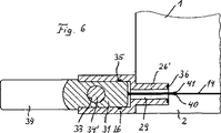
図6〜図9に示した原理的には同じ装置では、ノズルストリップ14のための迅速交換装置に変更が加えられている。迅速交換装置は本例では2つの互いに向かい合って圧接されたばね金属薄板40,41から成っており、これらのばね金属薄板40,41は差込栓31の端面に、重なり合ってかつノズルストリップ14に対して平行に固定されている。ばね金属薄板40,41の自由な端部において、ばね金属薄板40,41は図9aに示されているように曲げられて拡開している。この曲げられた領域において、下側に位置するばね金属薄板40に、短いスタッドまたは半球42が固定されており、半球42は、ばね金属薄板40,41が積層している場合、上側のばね金属薄板41に設けられた対応する孔43内に進入する。ノズルストリップ14はその端部に、これに対応する孔44を有しており、この孔44にばね金属薄板40の球42が、ストリップ14を差込栓31に取り付けるために進入する。図9eに示されているように、このような方法でノズルストリップ14は迅速に交換されている。両方のばね金属薄板40,41はノズルストリップ14の端部で曲げられて拡開されるだけでよく、交換プロセスは図9gおよび図9hに示されているような配置へと実施されることができる。
【0015】
さらに、図6〜図8に示した例では、ピン34′は鉛直ではなく水平に延びている。これにより、ピン34′はねじ27,28のための差込孔を切ってしまうけれども、ねじ27,28は深く埋設されており、しかも交換される必要は全くない。さらに、ピン34′はその自由な端部で閉鎖ユニット26から突出しており、そこでリング45を貫通しており、リング45は、規定通りに係止された閉鎖ユニット26のためのコンタクト提供器(Kontaktgeber)として働いている。さらに、閉鎖ユニットの側部に固定されたリング45は電気的に導線46を介してノズルビームの制御ユニットに接続されており、閉鎖ユニット26が規定通りにピン34′により封鎖されている場合にのみ、ノズルビームの水圧が高められることができる。
【図面の簡単な説明】
【図1】 従来慣用のノズルビームの長手方向断面図である。
【図2】 図1に示したノズルビームの端面を示す図である。
【図3】 ノズルビームの下側部分の構成を見て取ることができる、図1の線C−Cに沿った断面図である。
【図4】 図5に示した線IV−IVに沿った断面図であり、図1に示したノズルビームの両端面の一方にここではノズルストリップのための新しい迅速交換装置が追加されている。
【図5】 ノズルビームの端面の領域における装置の平面図である。
【図6】 図4に示した閉鎖ユニットに類似した、ノズルストリップの別の取付装置を備えた閉鎖ユニットの断面図である。
【図7】 差込栓が引き抜かれている閉鎖ユニットの、図6に示した断面図と同様の断面図である。
【図8】 図6に示した装置の平面図である。
【図9】 図6に示した迅速交換装置にノズルストリップを迅速に固定する方法を、順を追って概略的に示した側面図および平面図である。[0001]
The present invention is an electrode for hydrodynamic jet loading of fibers of a web guided along a beam, such as a fiber web, a fabric, a fabric, a woven fabric or a knitted fabric. A nozzle beam provided in a device for generating a fine liquid jet, the nozzle beam comprising an upper part and a lower part extending over the working width of the web, A pressure chamber that is circular when viewed in cross-section is arranged over its entire length, and a liquid under pressure is supplied to the pressure chamber, for example, on the end face side. A pressure distribution chamber is provided in the portion, and the pressure distribution chamber moves to a liquid outflow slit that is narrower than the cross section of the pressure distribution chamber, and is located above the liquid outflow slit. Nozzle strip are supported liquid-tightly in the nozzle beam, the nozzle strip, on what forms are exchangeable via a closeable opening in the end face of the nozzle beam.
[0002]
An apparatus of this kind is disclosed in German Offenlegungsschrift 19501738, the contents of which are described here as background art together with the drawings. A water pressure of up to 1000 bar is formed in the pressure chamber, and this water pressure naturally acts on the wall on the end face side of the nozzle beam. In order to make a hole in the beam, one end face must initially be open, but then it must be closed by a cover. Unique covers are provided for the pressure chambers and also for the pressure distribution chambers, and these covers are fixed to the nozzle beam wall by screws. A unique cover is also provided to close the nozzle strip exchange opening, which is also held on the nozzle beam wall by screws. In order to make a liquid-tight seal, a round string ring inserted in the wall to be sealed works each time.
[0003]
In order to replace the nozzle strip as necessary, after the water supply has been stopped, the two screws that are installed there and that secure the cover to the beam must be removed using a spanner or wrench. For reuse, the cover must be fixed on both sides with screws. Certainly only two screws need to be dissociated, but this requires a wrench, which can be regarded as a drawback.
[0004]
The object of the present invention is to improve the nozzle beam of the type described at the outset by providing a solution that allows quick replacement of the nozzle strip without mechanical disassembly, i.e. without the need for a spanner. is there.
[0005]
The above-described problem is that a closing unit is provided in the closable opening, and the closing unit is provided with an insertion slit for the nozzle strip at the height of the nozzle strip support portion. This is solved by the fact that the slit can be closed by a plug.
[0006]
The plug can be held by a pin fixed to the closure unit. This pin can be easily pulled out of the hole that secures the plug into the nozzle beam after the water supply is stopped, i.e. after the water pressure is stopped. Loss of the pin can be avoided by securing the pin to the nozzle beam, for example via a thread-like coupling means. The plug can be manually withdrawn from the closure unit, preferably with the nozzle strip, after which the nozzle strip can be inserted again with the plug after being replaced with a new strip.
[0007]
Hereinafter, embodiments of the present invention will be described in detail with reference to the drawings.
[0008]
A nozzle beam which can be seen from FIGS. 1 to 3 is known from German Offenlegungsschrift 19501738. This nozzle beam can be replaced here by another, but in principle similar nozzle beam. The housing of the nozzle beam consists of an
[0009]
The
[0010]
The
[0011]
In FIGS. 4 and 5, instead of the
[0012]
The
[0013]
As shown in FIG. 4, the
[0014]
In principle in the same apparatus as shown in FIGS. 6 to 9, the quick change device for the
[0015]
Furthermore, in the example shown in FIGS. 6 to 8, the
[Brief description of the drawings]
FIG. 1 is a longitudinal sectional view of a conventional nozzle beam.
FIG. 2 is a view showing an end face of the nozzle beam shown in FIG. 1;
3 is a cross-sectional view along the line CC in FIG. 1, where the configuration of the lower part of the nozzle beam can be seen.
4 is a cross-sectional view taken along line IV-IV shown in FIG. 5, with a new quick change device for the nozzle strip added here on one of the end faces of the nozzle beam shown in FIG. .
FIG. 5 is a plan view of the device in the region of the end face of the nozzle beam.
6 is a cross-sectional view of a closure unit with another attachment device for a nozzle strip, similar to the closure unit shown in FIG.
7 is a cross-sectional view similar to the cross-sectional view shown in FIG. 6 of the closing unit from which the plug has been pulled out.
FIG. 8 is a plan view of the apparatus shown in FIG. 6;
FIGS. 9A and 9B are a side view and a plan view schematically showing, in order, a method for quickly fixing a nozzle strip to the quick change device shown in FIG. 6;
Claims (18)
a)上側の部分にはその全長にわたって、横断面で見て円形の圧力室が配置されており、該圧力室に、圧力下にある液体が供給されており、
b)前記圧力室に対して平行に下側の部分内に圧力分配室が設けられており、
c)該圧力分配室が、圧力分配室の横断面に比して狭幅の液体流出スリットへと移行し、
d)該液体流出スリットの上部に、ノズルストリップが液密にノズルビーム内に支承されており、
e)前記ノズルストリップが、ノズルビームの端面に設けられた閉鎖可能な開口を介して交換可能である
形式のものにおいて、
f)閉鎖可能な開口に閉鎖ユニット(26)が設けられており、
g)該閉鎖ユニット(26)には、ノズルストリップ支承箇所の高さに、ノズルストリップ(14)のための差込スリット(29)が設けられており、
h)該差込スリット(29)が差込栓(31)により閉鎖可能であり、
i)該差込栓(31)が、閉鎖ユニット(26)内で固定されるピン(34,34′)によりノズルビーム(1,2)に保持されている
ことを特徴とする、ビームに沿って案内されたウェブの繊維をハイドロダイナミックに噴流負荷するための極微細な液体噴流を発生する装置に設けられたノズルビーム。It is a nozzle beam provided in a device for generating a very fine liquid jet for hydrodynamic jet loading of web fibers guided along the beam, such as textile web, thin fabric, woven fabric or knitted fabric. The nozzle beam consists of an upper part and a lower part extending over the working width of the web;
is over its entire length to the portion of a) the upper, as viewed in cross section is disposed a circular pressure chamber, the pressure chamber, the liquid under pressure are subjected fed,
b) a pressure distribution chamber is provided in the lower part parallel to the pressure chamber;
c) the pressure distribution chamber transitions to a liquid outlet slit which is narrower than the cross section of the pressure distribution chamber;
d) A nozzle strip is supported liquid-tightly in the nozzle beam above the liquid outflow slit,
e) in a form in which the nozzle strip is replaceable through a closable opening provided in the end face of the nozzle beam;
f) a closure unit (26) is provided in the closable opening;
g) The closure unit (26) is provided with an insertion slit (29) for the nozzle strip (14) at the height of the nozzle strip support location;
h)該差Komi slit (29) is Ri der closable by Sakomisen (31),
i) The plug (31) is held in the nozzle beam (1, 2) by pins (34, 34 ') fixed in the closure unit (26). A nozzle beam provided in a device for generating an extremely fine liquid jet for hydrodynamically loading the web fibers guided along the beam hydrodynamically.
Applications Claiming Priority (3)
| Application Number | Priority Date | Filing Date | Title |
|---|---|---|---|
| DE10107403 | 2001-02-14 | ||
| DE10112446A DE10112446A1 (en) | 2001-02-14 | 2001-03-13 | Closing unit for the nozzle strip on a nozzle bar for the hydrodynamic needling of fibers of a material web |
| PCT/EP2002/001275 WO2002064872A1 (en) | 2001-02-14 | 2002-02-07 | Closing unit for the nozzle strip on a nozzle beam for hydrodynamically needling fibres of a web of fabric |
Publications (2)
| Publication Number | Publication Date |
|---|---|
| JP2005502791A JP2005502791A (en) | 2005-01-27 |
| JP3977258B2 true JP3977258B2 (en) | 2007-09-19 |
Family
ID=26008526
Family Applications (1)
| Application Number | Title | Priority Date | Filing Date |
|---|---|---|---|
| JP2002564176A Expired - Lifetime JP3977258B2 (en) | 2001-02-14 | 2002-02-07 | Closure unit for nozzle strips on the nozzle beam that hydrodynamically entangles the fibers of the product web |
Country Status (9)
| Country | Link |
|---|---|
| US (1) | US6810565B2 (en) |
| EP (1) | EP1360360B1 (en) |
| JP (1) | JP3977258B2 (en) |
| AT (1) | ATE299197T1 (en) |
| BR (1) | BR0207224A (en) |
| CA (1) | CA2435922A1 (en) |
| DK (1) | DK1360360T3 (en) |
| TW (1) | TW565639B (en) |
| WO (1) | WO2002064872A1 (en) |
Families Citing this family (7)
| Publication number | Priority date | Publication date | Assignee | Title |
|---|---|---|---|---|
| JP4439854B2 (en) * | 2002-10-08 | 2010-03-24 | 三菱レイヨン・エンジニアリング株式会社 | Non-woven fabric manufacturing method using pressurized steam jet nozzle |
| FR2845934B1 (en) * | 2002-10-22 | 2004-12-24 | Rieter Perfojet | DEVICE FOR PROJECTING JETS WITH DOUBLE SHUTTERING. |
| DE102004049146A1 (en) * | 2004-10-07 | 2006-04-13 | Fleissner Gmbh | Wasservernadelungsvorrichtung |
| DE102005005463A1 (en) * | 2005-02-04 | 2006-08-10 | Fleissner Gmbh | Nozzle bar with means for adjusting the working width and method for adjusting the working width of a nozzle strip |
| DE102006004459B3 (en) * | 2006-01-30 | 2007-06-21 | Fleissner Gmbh | O-ring assembly device for nozzle beam of liquid jets producing device, has releasing device with releasing unit, which is provided with contact surface, on one side, where surface is moved against O-ring in specific position of unit |
| EP1908855B1 (en) * | 2006-10-06 | 2009-04-01 | Groz-Beckert KG | Nozzle beam for the treatment of textile |
| IT201600082924A1 (en) * | 2016-08-05 | 2018-02-05 | A C M Eng S R L | INJECTOR DEVICE FOR WATER JETS |
Family Cites Families (10)
| Publication number | Priority date | Publication date | Assignee | Title |
|---|---|---|---|---|
| US3403862A (en) * | 1967-01-06 | 1968-10-01 | Du Pont | Apparatus for preparing tanglelaced non-woven fabrics by liquid stream jets |
| US3613999A (en) * | 1970-04-29 | 1971-10-19 | Du Pont | Apparatus for jetting liquid onto fibrous material |
| US4085485A (en) * | 1976-07-26 | 1978-04-25 | International Paper Company | Process and device for forming non-woven fabrics |
| US5042722A (en) * | 1987-07-13 | 1991-08-27 | Honeycomb Systems, Inc. | Apparatus for jetting high velocity liquid streams onto fibrous materials |
| US4880168A (en) * | 1987-07-13 | 1989-11-14 | Honeycomb Systems, Inc. | Apparatus for jetting high velocity liquid streams onto fibrous materials |
| EP0725175B1 (en) * | 1995-01-23 | 1999-03-24 | FLEISSNER GmbH & Co. KG Maschinenfabrik | Manifold in an apparatus for jetting high velocity liquid streams |
| DE19501738A1 (en) * | 1995-01-23 | 1996-07-25 | Fleissner Maschf Gmbh Co | Jet beam for matting fibres in web |
| US5778501A (en) * | 1997-05-29 | 1998-07-14 | Yu-Hau Machinery Co., Ltd. | Water-jet machine for maufacturing non-woven fabric |
| DE19745661A1 (en) * | 1997-10-17 | 1999-04-22 | Fleissner Maschf Gmbh Co | Nozzle bar on a device for generating liquid jets |
| DE19828118A1 (en) * | 1998-06-24 | 1999-12-30 | Fleissner Maschf Gmbh Co | Device with a nozzle bar for generating liquid jets for the jet interlacing of fibers on a textile web |
-
2002
- 2002-02-07 BR BR0207224-6A patent/BR0207224A/en not_active Application Discontinuation
- 2002-02-07 EP EP02719780A patent/EP1360360B1/en not_active Revoked
- 2002-02-07 WO PCT/EP2002/001275 patent/WO2002064872A1/en not_active Application Discontinuation
- 2002-02-07 AT AT02719780T patent/ATE299197T1/en not_active IP Right Cessation
- 2002-02-07 DK DK02719780T patent/DK1360360T3/en active
- 2002-02-07 JP JP2002564176A patent/JP3977258B2/en not_active Expired - Lifetime
- 2002-02-07 CA CA002435922A patent/CA2435922A1/en not_active Abandoned
- 2002-02-07 US US10/467,319 patent/US6810565B2/en not_active Expired - Fee Related
- 2002-02-08 TW TW091102355A patent/TW565639B/en not_active IP Right Cessation
Also Published As
| Publication number | Publication date |
|---|---|
| JP2005502791A (en) | 2005-01-27 |
| EP1360360B1 (en) | 2005-07-06 |
| TW565639B (en) | 2003-12-11 |
| BR0207224A (en) | 2004-03-09 |
| ATE299197T1 (en) | 2005-07-15 |
| WO2002064872A1 (en) | 2002-08-22 |
| US6810565B2 (en) | 2004-11-02 |
| EP1360360A1 (en) | 2003-11-12 |
| DK1360360T3 (en) | 2005-10-31 |
| US20040103506A1 (en) | 2004-06-03 |
| CA2435922A1 (en) | 2002-08-22 |
Similar Documents
| Publication | Publication Date | Title |
|---|---|---|
| JP3977258B2 (en) | Closure unit for nozzle strips on the nozzle beam that hydrodynamically entangles the fibers of the product web | |
| US5042722A (en) | Apparatus for jetting high velocity liquid streams onto fibrous materials | |
| CA1166413A (en) | Process and apparatus for preparing uniform size polymer beads | |
| JPH08226056A (en) | Nozzle bar provided on apparatus for generating liquid flow | |
| KR200415015Y1 (en) | membrane filter of using connector and water purification system | |
| US3613999A (en) | Apparatus for jetting liquid onto fibrous material | |
| US1992938A (en) | Method of dispersion | |
| GB2208208A (en) | Apparatus for jetting high velocity liquid streams onto fibrous materials | |
| DE2637159B1 (en) | Steam iron machine | |
| JP4163872B2 (en) | Nozzle body and method for jet entanglement for generating very fine liquid jets in hydroentanglement devices | |
| US4251373A (en) | Squeeze-filter plate for use in filter press | |
| US4839664A (en) | Fluid-jet catcher with removable porous metal ingestion blade | |
| JPH09234321A (en) | Filter member attaching apparatus | |
| CN100462150C (en) | Doctor blade purge system | |
| JP5278879B2 (en) | Spot welding electrode | |
| US6012654A (en) | Nozzle beam on a device for generating liquid streams | |
| DE19614364B4 (en) | Printhead for an inkjet printer | |
| US4742642A (en) | Swabbing device for a herbicide applicator | |
| US2754084A (en) | Snatch block | |
| US2495031A (en) | Oil filter unit | |
| TW363112B (en) | Liquid forced-feed apparatus | |
| US2367873A (en) | Filter | |
| EP0108705A2 (en) | Apparatus for crimping textile fibrous materials | |
| US6945112B2 (en) | Testing device for the ultrasonic inspection of barstock | |
| EP0496394A2 (en) | Spinnerette blanketer |
Legal Events
| Date | Code | Title | Description |
|---|---|---|---|
| A621 | Written request for application examination |
Free format text: JAPANESE INTERMEDIATE CODE: A621 Effective date: 20041022 |
|
| A977 | Report on retrieval |
Free format text: JAPANESE INTERMEDIATE CODE: A971007 Effective date: 20070221 |
|
| A131 | Notification of reasons for refusal |
Free format text: JAPANESE INTERMEDIATE CODE: A131 Effective date: 20070223 |
|
| A601 | Written request for extension of time |
Free format text: JAPANESE INTERMEDIATE CODE: A601 Effective date: 20070323 |
|
| A602 | Written permission of extension of time |
Free format text: JAPANESE INTERMEDIATE CODE: A602 Effective date: 20070330 |
|
| A521 | Request for written amendment filed |
Free format text: JAPANESE INTERMEDIATE CODE: A523 Effective date: 20070525 |
|
| TRDD | Decision of grant or rejection written | ||
| A01 | Written decision to grant a patent or to grant a registration (utility model) |
Free format text: JAPANESE INTERMEDIATE CODE: A01 Effective date: 20070614 |
|
| A61 | First payment of annual fees (during grant procedure) |
Free format text: JAPANESE INTERMEDIATE CODE: A61 Effective date: 20070620 |
|
| FPAY | Renewal fee payment (event date is renewal date of database) |
Free format text: PAYMENT UNTIL: 20100629 Year of fee payment: 3 |
|
| R150 | Certificate of patent or registration of utility model |
Free format text: JAPANESE INTERMEDIATE CODE: R150 |