JP3973864B2 - Printed circuit board unit with cooling device and electronic device - Google Patents
Printed circuit board unit with cooling device and electronic device Download PDFInfo
- Publication number
- JP3973864B2 JP3973864B2 JP2001281683A JP2001281683A JP3973864B2 JP 3973864 B2 JP3973864 B2 JP 3973864B2 JP 2001281683 A JP2001281683 A JP 2001281683A JP 2001281683 A JP2001281683 A JP 2001281683A JP 3973864 B2 JP3973864 B2 JP 3973864B2
- Authority
- JP
- Japan
- Prior art keywords
- circuit board
- printed circuit
- fan
- fan case
- cooling device
- Prior art date
- Legal status (The legal status is an assumption and is not a legal conclusion. Google has not performed a legal analysis and makes no representation as to the accuracy of the status listed.)
- Expired - Fee Related
Links
Images


Classifications
-
- H—ELECTRICITY
- H05—ELECTRIC TECHNIQUES NOT OTHERWISE PROVIDED FOR
- H05K—PRINTED CIRCUITS; CASINGS OR CONSTRUCTIONAL DETAILS OF ELECTRIC APPARATUS; MANUFACTURE OF ASSEMBLAGES OF ELECTRICAL COMPONENTS
- H05K1/00—Printed circuits
- H05K1/02—Details
- H05K1/0272—Adaptations for fluid transport, e.g. channels, holes
-
- G—PHYSICS
- G06—COMPUTING; CALCULATING OR COUNTING
- G06F—ELECTRIC DIGITAL DATA PROCESSING
- G06F1/00—Details not covered by groups G06F3/00 - G06F13/00 and G06F21/00
- G06F1/16—Constructional details or arrangements
- G06F1/20—Cooling means
- G06F1/203—Cooling means for portable computers, e.g. for laptops
-
- H—ELECTRICITY
- H05—ELECTRIC TECHNIQUES NOT OTHERWISE PROVIDED FOR
- H05K—PRINTED CIRCUITS; CASINGS OR CONSTRUCTIONAL DETAILS OF ELECTRIC APPARATUS; MANUFACTURE OF ASSEMBLAGES OF ELECTRICAL COMPONENTS
- H05K1/00—Printed circuits
- H05K1/02—Details
- H05K1/0201—Thermal arrangements, e.g. for cooling, heating or preventing overheating
- H05K1/0203—Cooling of mounted components
- H05K1/0209—External configuration of printed circuit board adapted for heat dissipation, e.g. lay-out of conductors, coatings
-
- H—ELECTRICITY
- H01—ELECTRIC ELEMENTS
- H01L—SEMICONDUCTOR DEVICES NOT COVERED BY CLASS H10
- H01L2924/00—Indexing scheme for arrangements or methods for connecting or disconnecting semiconductor or solid-state bodies as covered by H01L24/00
- H01L2924/0001—Technical content checked by a classifier
- H01L2924/0002—Not covered by any one of groups H01L24/00, H01L24/00 and H01L2224/00
-
- H—ELECTRICITY
- H05—ELECTRIC TECHNIQUES NOT OTHERWISE PROVIDED FOR
- H05K—PRINTED CIRCUITS; CASINGS OR CONSTRUCTIONAL DETAILS OF ELECTRIC APPARATUS; MANUFACTURE OF ASSEMBLAGES OF ELECTRICAL COMPONENTS
- H05K2201/00—Indexing scheme relating to printed circuits covered by H05K1/00
- H05K2201/06—Thermal details
- H05K2201/064—Fluid cooling, e.g. by integral pipes
-
- H—ELECTRICITY
- H05—ELECTRIC TECHNIQUES NOT OTHERWISE PROVIDED FOR
- H05K—PRINTED CIRCUITS; CASINGS OR CONSTRUCTIONAL DETAILS OF ELECTRIC APPARATUS; MANUFACTURE OF ASSEMBLAGES OF ELECTRICAL COMPONENTS
- H05K2201/00—Indexing scheme relating to printed circuits covered by H05K1/00
- H05K2201/09—Shape and layout
- H05K2201/09009—Substrate related
- H05K2201/09072—Hole or recess under component or special relationship between hole and component
-
- H—ELECTRICITY
- H05—ELECTRIC TECHNIQUES NOT OTHERWISE PROVIDED FOR
- H05K—PRINTED CIRCUITS; CASINGS OR CONSTRUCTIONAL DETAILS OF ELECTRIC APPARATUS; MANUFACTURE OF ASSEMBLAGES OF ELECTRICAL COMPONENTS
- H05K2201/00—Indexing scheme relating to printed circuits covered by H05K1/00
- H05K2201/09—Shape and layout
- H05K2201/09209—Shape and layout details of conductors
- H05K2201/09654—Shape and layout details of conductors covering at least two types of conductors provided for in H05K2201/09218 - H05K2201/095
- H05K2201/09772—Conductors directly under a component but not electrically connected to the component
-
- H—ELECTRICITY
- H05—ELECTRIC TECHNIQUES NOT OTHERWISE PROVIDED FOR
- H05K—PRINTED CIRCUITS; CASINGS OR CONSTRUCTIONAL DETAILS OF ELECTRIC APPARATUS; MANUFACTURE OF ASSEMBLAGES OF ELECTRICAL COMPONENTS
- H05K2201/00—Indexing scheme relating to printed circuits covered by H05K1/00
- H05K2201/09—Shape and layout
- H05K2201/09209—Shape and layout details of conductors
- H05K2201/09654—Shape and layout details of conductors covering at least two types of conductors provided for in H05K2201/09218 - H05K2201/095
- H05K2201/09781—Dummy conductors, i.e. not used for normal transport of current; Dummy electrodes of components
Description
【0001】
【発明の属する技術分野】
本発明は、例えば携帯情報端末(PDA)やノートブックパーソナルコンピュータといった電子機器に組み込まれる冷却装置付きプリント基板ユニットに関し、特に、プリント基板と、プリント基板の表面で交差する回転中心回りで回転するファンと、ファンを収容するファンケースとを備えるプリント基板ユニットに関する。
【0002】
【従来の技術】
例えば特開2000−77877号公報に開示されるように、いわゆるファンユニットは、回転軸回りで回転するファンを収容するファンケースを備える。ファンが回転すると、回転中心から遠心方向に空気は吹き飛ばされる。吹き飛ばされた空気はファンケースに案内されて排気口まで導かれる。こうして排気口から空気が排出される一方で、ファンケース内には吸気口から周囲の空気が取り込まれる。こうした吸気口はプリント基板の表面に向き合わせられる。ファンケース内に空気が吸引されると、プリント基板の表面に沿って気流は生み出される。
【0003】
【発明が解決しようとする課題】
一般に、プリント基板の表面には多数の電子部品が搭載される。電子部品の出っ張りは滑らかな空気の流れを阻害する。こうした気流の乱れはファンの吸気を妨げる。吸気量は減少する。ファンの冷却効率は低下する。プリント基板ユニットの薄型化が進むほど、ファンケースとプリント基板の表面との間隔は狭められる。ファンの冷却効率は一層低下してしまう。
【0004】
本発明は、上記実状に鑑みてなされたもので、電子機器の薄型化に大いに貢献することができる冷却装置付きプリント基板ユニットを提供することを目的とする。
【0005】
上記目的を達成するために、第1発明によれば、プリント基板と、プリント基板の表面と平行な面に交差する回転中心回りで回転するファンと、ファンの周囲でプリント基板の表面から立ち上がるファンケース用壁体と、ファンケース用壁体で区画される排気口とを備えることを特徴とする冷却装置付きプリント基板ユニットが提供される。
【0006】
プリント基板およびファンケース用壁体は、協働で、ファンを収容する空間を区画することができる。ファンが回転すると、空間内には空気の移動すなわち気流が引き起こされる。プリント基板およびファンケース用壁体は排気口まで気流を誘導する。このようにプリント基板は冷却装置の一部を担う。
【0007】
特に、こういったプリント基板ユニットでは、空間内で高速な気流が生成されることができる。こういった気流は効率的にプリント基板から熱を奪うことができる。プリント基板の放熱は促進される。一般に、プリント基板の表面には金属製の導電配線パターンが張り巡らされる。こういった導電配線パターンは、プリント基板の材質に比べて優れた熱伝導特性を備えることが多い。導電配線パターンはプリント基板の放熱に大いに貢献することができる。特に、導電配線パターンがファンケース用壁体の内側で広がれば、プリント基板の放熱は大いに促進されることができる。
【0008】
冷却装置付きプリント基板ユニットは、ファンケース用壁体の上端に接続されて、プリント基板の表面に平行な基準面に沿って広がる天井壁と、この天井壁に形成される吸気口とをさらに備えてもよい。
【0009】
一般に、プリント基板の表面には多数の電子部品が搭載される。プリント基板の表面から電子部品は出っ張る。こういった電子部品の出っ張りは滑らかな空気の流れを阻害すると考えられる。プリント基板の表面から所定の高さで吸気口が開口すれば、電子部品の出っ張りにも拘わらず、比較的に良好な空気の流れは形成されることができる。吸気口にスムースに空気は流れ込むことができる。多量の空気が注入される結果、冷却装置の冷却効率は高められることができる。
【0010】
例えばこういった冷却装置付きプリント基板ユニットが電子機器に組み込まれると、吸気口は電子機器の筐体の内面に向き合わせられることができる。吸気口からファンケース用壁体の内側に向かって空気が吸入されると、筐体の内面に沿って気流は生み出される。一般に、筐体の内面はプリント基板の表面に比べて滑らかな平坦面に形成される。空気の流れを阻害する障害物はほとんど存在しない。筐体の内面に沿って滑らかな気流は生成される。こうして吸気口には滑らかに空気が流れ込むことから、吸気口と筐体の内面との間隔が狭められても、十分な冷却効率は確保されることができる。電子機器の薄型化は確実に実現されることができる。
【0011】
こういった冷却装置付きプリント基板ユニットは、ファンケース用壁体の内側でプリント基板に穿たれる吸気口をさらに備えてもよい。こうした吸気口によれば、プリント基板の表側だけでなく裏側からもファンに向かって空気は流れ込むことができる。プリント基板およびファンケース用壁体で区画される空間に大量の空気は取り込まれることができる。こうして大量の吸気量が確保される結果、冷却装置の冷却効率は一層高められることができる。しかも、プリント基板の表側および裏側は同時に冷却されることができる。ただし、冷却装置付きプリント基板ユニットでは、天井壁に区画される吸気口に代えて、プリント基板側の吸気口のみが確保されてもよい。こういった構成は電子機器の一層の薄型化に寄与することができる。
【0012】
その他、冷却装置付きプリント基板ユニットは、前記プリント基板上に実装される電子部品と、前記ファンケース用壁体の内側でプリント基板の表面に沿って延び、電子部品に接続される導電配線パターンとをさらに備えてもよい。こういった冷却装置付きプリント基板ユニットでは、前述のファンの働きで導電配線パターンから効率的に放熱は実現される。プリント基板の放熱は促進される。しかも、導電配線パターンには、電子部品から効率的に熱が伝達されることから、電子部品は効率的に冷却されることができる。
【0013】
導電配線パターンには、プリント基板に取り付けられる放熱フィンが接続されてもよい。放熱フィンは、導電配線パターンからの放熱を一層促進することができる。こういった放熱フィンは、前述の排気口内に配置されてもよく、前述の排気口に向き合わせられてもよい。
【0014】
プリント基板の表面には、ファンケース用壁体の内側で電子部品が実装されてもよい。前述のようにファンケース用壁体の内側では羽根の働きで高速な気流は生成されることができる。したがって、電子部品は効率的に冷却されることができる。こういった電子部品は例えば前述の排気口内に配置されればよい。
【0015】
【発明の実施の形態】
以下、添付図面を参照しつつ本発明の一実施形態を説明する。
【0016】
図1は電子機器の一具体例すなわちノートブックパーソナルコンピュータ(ノートパソコン)11の外観を示す。このノートパソコン11は、薄型の機器本体12と、この機器本体12に揺動自在に連結されるディスプレイ用筐体13とを備える。機器本体12の表面には、キーボード14やポインティングデバイス15といった入力装置が組み込まれる。使用者は、キーボード14やポインティングデバイス15を利用してノートパソコン11の動作を操作することができる。
【0017】
ディスプレイ用筐体13には例えばLCD(液晶ディスプレイ)パネルモジュール16が組み込まれる。LCDパネルモジュール16の表示画面は、ディスプレイ用筐体13に区画される窓孔17に臨む。使用者は、例えばLCDパネルモジュール16の表示画面に現れるテキストやグラフィックスに基づきノートパソコン11の動作を確認することができる。ディスプレイ用筐体13は、機器本体12に対する揺動を通じて機器本体12に重ね合わせられることができる。
【0018】
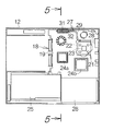
図2に示されるように、機器本体12にはプリント基板ユニット18が組み込まれる。プリント基板ユニット18は、プリント基板19と、このプリント基板19の表側表面に実装される中央演算処理ユニット(CPU)パッケージ21とを備える。CPUパッケージ21は、例えば小型のセラミック製基板22と、この基板22上に搭載されるCPUチップ23とを備えればよい。プリント基板19の表側表面には、CPUパッケージ21だけでなく様々な電子部品24a、24bが実装される。CPUパッケージ21とその他の電子部品24a、24b…との間や電子部品24a、24b…同士の間には、プリント基板19の表側表面に張り巡らされる導電配線パターン(図示されず)の働きで電気的接続が確立される。
【0019】
プリント基板ユニット18には、例えば機器本体12に着脱自在に組み込まれる蓄電池25やハードディスク駆動装置(HDD)26が接続される。蓄電池25は、例えばAC電源すなわち商用電源に代わってプリント基板ユニット18に向けて電力を供給することができる。ハードディスク駆動装置26には、CPUチップ23で処理されるアプリケーションプログラムや、アプリケーションプログラムの実行にあたって利用される様々なデータが格納される。
【0020】
CPUパッケージ21には本発明の第1実施形態に係る冷却装置27が接続される。この冷却装置27は、CPUチップ23の上面に重ね合わせられる伝熱板28を備える。この伝熱板28には、例えばヒートパイプ29といった熱伝導部材の一端が接続される。ヒートパイプ29の他端は、プリント基板19に取り付けられる放熱フィン31に接続される。CPUチップ23の熱は、伝熱板28およびヒートパイプ29を経て放熱フィン31まで伝達される。放熱フィン31は、プリント基板19に形成される切り欠き32からプリント基板19の裏側に突き出る。
【0021】
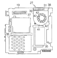
図3に示されるように、プリント基板19の裏側表面には、RAMといったメモリモジュール35やPCカードスロット36、LAN(ローカルエリアネットワーク)モジュール37といった電子部品が実装される。このように、プリント基板19の裏側には、プリント基板19の表側に比べて比較的に背の高い電子部品が実装される。
【0022】
冷却装置27には、図3に示されるように、プリント基板19の裏側表面に取り付けられるファンユニット38がさらに組み込まれる。このファンユニット38は、プリント基板19の裏側表面に固定されるファンケース39を備える。ファンケース39には、プリント基板19の裏側表面に平行な基準面に沿って広がる天井壁41が区画される。天井壁41には、ファンケース39内の空間とファンケース39外の空間とを相互に接続する吸気口42が区画される。
【0023】
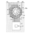
図4を併せて参照すると明らかなように、ファンケース39内には、プリント基板19の裏側表面に直交する回転中心CR回りで回転する回転体43が収容される。回転体43の周囲には、回転体43から放射状に広がる複数枚の羽根44が一体に形成される。羽根44は回転体43の周囲に例えば等間隔に配置されればよい。各羽根44は、回転中心CRを含む垂直面VPに対して所定の傾斜角αで交差する平面に沿って広がる。回転体43が回転すると、羽根44は、回転中心CRから遠心方向に空気を送り出すことができる。こうして回転体43および羽根44はいわゆるファンを構成する。
【0024】
ファンケース39には、図4から明らかなように、羽根44の周囲でプリント基板19の裏側表面から立ち上がるファンケース用壁体45が区画される。ファンケース用壁体45の内面は羽根44の外端に向き合わせられる。ファンケース用壁体45の切れ目で排気口46は区画される。排気口46は前述の放熱フィン31に向き合わせられる。ファンケース用壁体45の内側ではプリント基板19に吸気口47が穿たれる。この吸気口47は、前述の吸気口42と同様に、ファンケース39内の空間とファンケース39外の空間とを相互に接続する。プリント基板19はファンケース39の一部を構成する。
【0025】
図5から明らかなように、ファンユニット38の回転体43は、プリント基板19の裏側表面に直交する垂直方向に沿って延びる回転軸51に装着される。回転軸51は、ファンケース39の天井壁41に固定される軸受け52に支持される。回転体43と軸受け52との間には薄型電動モータ53が組み込まれる。電動モータ53は、例えば回転体43に取り付けられる永久磁石54と、軸受け52側に取り付けられて永久磁石54に向き合わせられるコイル55とで構成されればよい。こういった電動モータ53の動作は、制御基板56に実装される制御回路の働きで制御されることができる。
【0026】
いま、電動モータ53に電力が供給されると、回転中心CR回りで回転体43は回転する。羽根44は回転中心CRから遠心方向に空気を送り出す。送り出された空気はファンケース用壁体45の働きで排気口46まで誘導される。こうして排気口46から空気は吐き出される。
【0027】
機器本体12の筐体57には、ファンユニット38の排気口46に向き合わせられる開口58が形成される。排気口46から吐き出された空気は、放熱フィン31から熱を奪った後に、開口58から機器本体12の外部に逃される。こうして放熱フィン31の放熱は効率的に促進される。
【0028】
プリント基板19、ファンケース用壁体45および天井壁41で囲まれる内部空間では羽根44の回転に基づき高速な気流が生成される。こういった気流は効率的にプリント基板19の表面から熱を奪うことができる。プリント基板19の放熱は促進される。一般に、プリント基板19の表面には金属製の導電配線パターンが張り巡らされる。こういった導電配線パターンは、プリント基板19の材質に比べて優れた熱伝導特性を備えることから、プリント基板19の放熱に貢献することができる。特に、導電配線パターンがファンケース用壁体45の内側で広がれば、プリント基板19の放熱は大いに促進されることができる。
【0029】
こうして排気口46から空気が排出される一方で、ファンケース39内には吸気口42から周囲の空気は取り込まれる。ここで、天井壁41に形成された吸気口42は機器本体12の筐体57内面に向き合わせられることから、吸気口42からファンケース39内に空気が吸引されると、機器本体12の筐体57内面に沿って気流61は生み出される。一般に、プリント基板19の裏側表面には多数の電子部品が実装される。プリント基板19の裏側表面から電子部品は出っ張る。こういった電子部品の出っ張りは滑らかな空気の流れを阻害すると考えられる。その一方で、機器本体12の筐体57内面はプリント基板19の表面に比べて滑らかな平坦面に形成される。空気の流れを阻害する障害物はほとんど存在しない。機器本体12の筐体57内面に沿って滑らかな気流61は生成される。吸気口42にスムースに空気は流れ込むことができる。多量の空気が注入される結果、ファンユニット38の冷却効率は高められることができる。こうして吸気口42には滑らかに空気が流れ込むことから、ファンケース39の天井壁41と筐体57内面との間隔が狭められても、十分な冷却効率は確保されることができる。
【0030】
同時に、ファンユニット38では、プリント基板19に穿たれた吸気口47から空気は取り込まれることができる。こうして、ファンユニット38には、プリント基板19の裏側だけでなく表側からも空気が流れ込むことができる。大量の吸気量が確保される結果、ファンユニット38の冷却効率は一層高められることができる。しかも、ファンユニット38はプリント基板19の裏側に配置されるにも拘わらず、プリント基板19の表側は比較的に高い効率で冷却されることができる。
【0031】
こうしてプリント基板19に吸気口47が確保される場合には、例えば図6に示されるように、ファンケース39の天井壁41は完全に筐体57内面に重ね合わせられてもよい。こうして吸気口42が閉鎖されても、ファンケース39内には吸気口47から十分な空気の供給は確保されることができる。したがって、ファンユニット38では十分な冷却効率は維持されることができる。こういった構成によれば、機器本体12の一層の薄型化は実現されることができる。
【0032】
図7は本発明の第2実施形態に係る冷却装置62を示す。この冷却装置62は、プリント基板19の表側表面に沿って電力消費回路すなわちCPUパッケージ21から延びる導電配線パターン63と、プリント基板19の表側表面に実装されて、導電配線パターン63に接続される放熱フィン64とを備える。放熱フィン64は、例えばプリント基板19上で導電配線パターン63にはんだ付けされればよい。こういった導電配線パターン63はCPUパッケージ21の接地用配線として利用されればよい。図中、前述の第1実施形態の構成と均等な作用や機能を発揮する構成には同一の参照符号が付される。
【0033】
この冷却装置62では、プリント基板19の表側表面にファンユニット38aが取り付けられる。このファンユニット38aは前述の第1実施形態に係るファンユニット38と同様な構成を備えればよい。放熱フィン64は例えばファンユニット38aの排気口46内に配置されればよい。しかも、ファンケース用壁体46の内側には、CPUパッケージ21から放熱フィン64に至る導電配線パターン63が張り巡らされる。
【0034】
こういった冷却装置62によれば、前述と同様に、ファンユニット38aのファンケース39内で引き起こされる高速な気流の働きでプリント基板19の放熱は実現される。導電配線パターン63はプリント基板19の放熱を大いに促進する。しかも、導電配線パターン63にはCPUパッケージ21から効率的に熱が伝達されることから、CPUパッケージ21は効率的に冷却されることができる。
【0035】
排気口46から吐き出された空気は放熱フィン64から熱を奪い取る。こうして熱を奪い取った空気は、前述と同様に、筐体57の開口58から機器本体12の外部に逃される。こうして放熱フィン64では効率的な放熱は実現される。その他、こういった放熱フィン64には、電子部品24a、24b…といった他の電力消費回路から接地用の導電配線パターンが接続されてもよい。
【0036】
図8は本発明の第3実施形態に係る冷却装置を示す。この冷却装置66は前述と同様なファンユニット38を備える。このファンユニット38では、ファンケース用壁体45の内側でプリント基板19の表側表面に電子部品67が実装される。電子部品67は例えばファンユニット38の排気口46内に配置されればよい。こういった冷却装置66によれば、前述と同様に、ファンユニット38のファンケース39内で引き起こされる高速な気流の働きで電子部品67の放熱は実現されることができる。図中、前述の第1実施形態の構成と均等な作用や機能を発揮する構成には同一の参照符号が付される。
【0037】
なお、以上のような冷却装置27、62、66付きプリント基板ユニット18は、前述のノートパソコン11や携帯情報端末(PDA)といった携帯型の電子機器のほか、据え置き型の電子機器に組み込まれてもよい。前述のファンユニット38、38aでは、回転軸51の軸受け52は直接にプリント基板19に固定されてもよい。
【0038】
【発明の効果】
以上のように本発明によれば、冷却装置付きプリント基板ユニットは電子機器の薄型化に大いに貢献することができる。
【図面の簡単な説明】
【図1】 電子機器の一具体例に係るノートブックパーソナルコンピュータの外観を概略的に示す斜視図である。
【図2】 機器本体の内部構造およびプリント基板ユニットの表側表面を概略的に示す平面図である。
【図3】 プリント基板ユニットの裏側表面を概略的に示す拡大平面図である。
【図4】 本発明の第1実施形態に係る冷却装置の主要部を概略的に示すプリント基板の拡大平面図である。
【図5】 図2の5−5線に沿った拡大部分断面図である。
【図6】 図5に対応し、冷却装置の一変形例を概略的に示す拡大部分断面図である。
【図7】 図4に対応し、本発明の第2実施形態に係る冷却装置の構成を概略的に示すプリント基板の拡大平面図である。
【図8】 図4に対応し、本発明の第3実施形態に係る冷却装置の構成を概略的に示すプリント基板の拡大平面図である。
【符号の説明】
11 電子機器としてのノートブックパーソナルコンピュータ、18 冷却装置付きプリント基板ユニット、19 プリント基板、21 電子部品および電力消費回路としてのCPU(中央演算処理ユニット)パッケージ、27 冷却装置、41 天井壁、42 吸気口、43 ファンを構成する回転体、44 ファンを構成する羽根、45 ファンケース用壁体、47 吸気口、62 冷却装置、63 導電配線パターン、64 放熱フィン、66 冷却装置、67 電子部品、CR 回転中心。[0001]
BACKGROUND OF THE INVENTION
The present invention relates to a printed circuit board unit with a cooling device incorporated in an electronic device such as a personal digital assistant (PDA) or a notebook personal computer, and in particular, a fan that rotates about a rotation center intersecting the printed circuit board and the surface of the printed circuit board. And a printed circuit board unit including a fan case that houses the fan.
[0002]
[Prior art]
For example, as disclosed in Japanese Patent Application Laid-Open No. 2000-77877, a so-called fan unit includes a fan case that houses a fan that rotates about a rotation axis. When the fan rotates, air is blown away from the rotation center in the centrifugal direction. The blown air is guided to the fan case and guided to the exhaust port. Thus, while air is discharged from the exhaust port, ambient air is taken into the fan case from the intake port. These air inlets face the surface of the printed circuit board. When air is sucked into the fan case, an air flow is generated along the surface of the printed circuit board.
[0003]
[Problems to be solved by the invention]
In general, a large number of electronic components are mounted on the surface of a printed circuit board. Protrusion of electronic components obstructs smooth air flow. Such turbulence disturbs the intake of the fan. The intake air amount decreases. The cooling efficiency of the fan decreases. As the printed circuit board unit becomes thinner, the distance between the fan case and the surface of the printed circuit board is reduced. The cooling efficiency of the fan is further reduced.
[0004]
The present invention has been made in view of the above circumstances, and an object thereof is to provide a printed circuit board unit with a cooling device that can greatly contribute to a reduction in thickness of an electronic device.
[0005]
To achieve the above object, according to the first invention, a printed circuit board, a fan that rotates about a rotation center that intersects a plane parallel to the surface of the printed circuit board, and a fan that rises from the surface of the printed circuit board around the fan. There is provided a printed circuit board unit with a cooling device comprising a case wall and an exhaust port defined by a fan case wall.
[0006]
The printed circuit board and the fan case wall can cooperate to define a space for accommodating the fan. When the fan rotates, air movement, that is, airflow is caused in the space. The printed circuit board and the fan case wall induce airflow to the exhaust port. Thus, the printed circuit board serves as a part of the cooling device.
[0007]
In particular, in such a printed circuit board unit, a high-speed air current can be generated in the space. Such an air flow can efficiently remove heat from the printed circuit board. Heat dissipation of the printed circuit board is promoted. Generally, a metal conductive wiring pattern is stretched around the surface of a printed board. Such conductive wiring patterns often have excellent thermal conductivity characteristics compared to the material of the printed circuit board. The conductive wiring pattern can greatly contribute to heat dissipation of the printed circuit board. In particular, if the conductive wiring pattern spreads inside the fan case wall, heat dissipation of the printed circuit board can be greatly promoted.
[0008]
The printed circuit board unit with a cooling device further includes a ceiling wall connected to the upper end of the wall for the fan case and extending along a reference plane parallel to the surface of the printed circuit board, and an air inlet formed in the ceiling wall. May be.
[0009]
In general, a large number of electronic components are mounted on the surface of a printed circuit board. Electronic components protrude from the surface of the printed circuit board. These protrusions of electronic components are thought to hinder smooth air flow. If the intake port opens at a predetermined height from the surface of the printed circuit board, a relatively good air flow can be formed despite the protrusion of the electronic component. Air can flow smoothly into the air intake. As a result of injecting a large amount of air, the cooling efficiency of the cooling device can be increased.
[0010]
For example, when such a printed circuit board unit with a cooling device is incorporated into an electronic device, the air inlet can face the inner surface of the housing of the electronic device. When air is sucked from the air inlet to the inside of the fan case wall, an air flow is generated along the inner surface of the housing. In general, the inner surface of the housing is formed on a smooth flat surface as compared with the surface of the printed circuit board. There are few obstacles that obstruct air flow. A smooth airflow is generated along the inner surface of the housing. Since air smoothly flows into the intake port in this way, sufficient cooling efficiency can be ensured even if the interval between the intake port and the inner surface of the housing is reduced. Thinning of electronic devices can be realized with certainty.
[0011]
Such a printed circuit board unit with a cooling device may further include an air inlet that is formed in the printed circuit board inside the fan case wall. According to such an air inlet, air can flow toward the fan not only from the front side of the printed circuit board but also from the back side. A large amount of air can be taken into the space defined by the printed circuit board and the fan case wall. As a result of securing a large amount of intake air in this way, the cooling efficiency of the cooling device can be further enhanced. Moreover, the front side and the back side of the printed circuit board can be cooled simultaneously. However, in the printed circuit board unit with a cooling device, instead of the air intake port defined in the ceiling wall, only the air intake port on the printed circuit board side may be secured. Such a configuration can contribute to further thinning of the electronic device.
[0012]
In addition, the printed circuit board unit with a cooling device includes an electronic component mounted on the printed circuit board, a conductive wiring pattern extending along the surface of the printed circuit board inside the fan case wall, and connected to the electronic component. May be further provided. In such a printed circuit board unit with a cooling device, heat can be efficiently dissipated from the conductive wiring pattern by the function of the above-described fan. Heat dissipation of the printed circuit board is promoted. Moreover, since heat is efficiently transferred from the electronic component to the conductive wiring pattern, the electronic component can be efficiently cooled.
[0013]
A radiating fin attached to the printed circuit board may be connected to the conductive wiring pattern. The heat radiation fin can further promote the heat radiation from the conductive wiring pattern. Such heat radiating fins may be disposed in the above-described exhaust port, or may be opposed to the above-described exhaust port.
[0014]
An electronic component may be mounted on the surface of the printed board inside the fan case wall. As described above, a high-speed air current can be generated inside the fan case wall by the action of the blades. Therefore, the electronic component can be efficiently cooled. Such electronic components may be disposed in the above-described exhaust port, for example.
[0015]
DETAILED DESCRIPTION OF THE INVENTION
Hereinafter, an embodiment of the present invention will be described with reference to the accompanying drawings.
[0016]
FIG. 1 shows an example of an electronic device, that is, an external appearance of a notebook personal computer (notebook personal computer) 11. The
[0017]
For example, an LCD (liquid crystal display)
[0018]
As shown in FIG. 2, a printed
[0019]
For example, a
[0020]
The
[0021]
As shown in FIG. 3, electronic components such as a
[0022]
As shown in FIG. 3, the
[0023]
As is clear from FIG. 4, the
[0024]
As is apparent from FIG. 4, a
[0025]
As is clear from FIG. 5, the rotating
[0026]
Now, when electric power is supplied to the
[0027]
An
[0028]
In the internal space surrounded by the printed
[0029]
In this way, air is discharged from the
[0030]
At the same time, in the
[0031]
When the
[0032]
FIG. 7 shows a
[0033]
In the
[0034]
According to such a
[0035]
The air discharged from the
[0036]
FIG. 8 shows a cooling device according to a third embodiment of the present invention. The
[0037]
The printed
[0038]
【The invention's effect】
As described above, according to the present invention, the printed circuit board unit with a cooling device can greatly contribute to the reduction in thickness of the electronic device.
[Brief description of the drawings]
FIG. 1 is a perspective view schematically showing an appearance of a notebook personal computer according to a specific example of an electronic apparatus.
FIG. 2 is a plan view schematically showing an internal structure of a device main body and a front surface of a printed circuit board unit.
FIG. 3 is an enlarged plan view schematically showing a back surface of the printed circuit board unit.
FIG. 4 is an enlarged plan view of a printed circuit board schematically showing the main part of the cooling device according to the first embodiment of the present invention.
5 is an enlarged partial sectional view taken along line 5-5 of FIG.
FIG. 6 is an enlarged partial sectional view schematically showing a modification of the cooling device corresponding to FIG. 5;
FIG. 7 is an enlarged plan view of a printed circuit board corresponding to FIG. 4 and schematically showing the configuration of a cooling device according to a second embodiment of the present invention.
FIG. 8 is an enlarged plan view of a printed circuit board corresponding to FIG. 4 and schematically showing a configuration of a cooling device according to a third embodiment of the present invention.
[Explanation of symbols]
DESCRIPTION OF
Claims (12)
Priority Applications (6)
| Application Number | Priority Date | Filing Date | Title |
|---|---|---|---|
| JP2001281683A JP3973864B2 (en) | 2001-09-17 | 2001-09-17 | Printed circuit board unit with cooling device and electronic device |
| US10/096,509 US6665181B2 (en) | 2001-09-17 | 2002-03-13 | Cooling device capable of reducing thickness of electronic apparatus |
| US10/664,933 US6909604B2 (en) | 2001-09-17 | 2003-09-22 | Cooling device capable of reducing thickness of electronic apparatus |
| US11/120,979 US7019970B2 (en) | 2001-09-17 | 2005-05-04 | Cooling device capable of reducing thickness of electronic apparatus |
| US11/369,840 US7298616B2 (en) | 2001-09-17 | 2006-03-08 | Cooling device capable of reducing thickness of electronic apparatus |
| US11/905,895 US7474533B2 (en) | 2001-09-17 | 2007-10-05 | Cooling device capable of reducing thickness of electronic apparatus |
Applications Claiming Priority (1)
| Application Number | Priority Date | Filing Date | Title |
|---|---|---|---|
| JP2001281683A JP3973864B2 (en) | 2001-09-17 | 2001-09-17 | Printed circuit board unit with cooling device and electronic device |
Related Child Applications (2)
| Application Number | Title | Priority Date | Filing Date |
|---|---|---|---|
| JP2006201126A Division JP4588672B2 (en) | 2006-07-24 | 2006-07-24 | Printed circuit board unit with cooling device and electronic device |
| JP2007127413A Division JP4588741B2 (en) | 2007-05-11 | 2007-05-11 | Printed circuit board unit with cooling device and electronic device |
Publications (3)
| Publication Number | Publication Date |
|---|---|
| JP2003092483A JP2003092483A (en) | 2003-03-28 |
| JP2003092483A5 JP2003092483A5 (en) | 2005-10-20 |
| JP3973864B2 true JP3973864B2 (en) | 2007-09-12 |
Family
ID=19105463
Family Applications (1)
| Application Number | Title | Priority Date | Filing Date |
|---|---|---|---|
| JP2001281683A Expired - Fee Related JP3973864B2 (en) | 2001-09-17 | 2001-09-17 | Printed circuit board unit with cooling device and electronic device |
Country Status (2)
| Country | Link |
|---|---|
| US (4) | US6665181B2 (en) |
| JP (1) | JP3973864B2 (en) |
Families Citing this family (53)
| Publication number | Priority date | Publication date | Assignee | Title |
|---|---|---|---|---|
| WO2003002918A2 (en) * | 2001-06-27 | 2003-01-09 | Advanced Rotary Systems, Llc | Cooler for electronic devices |
| US7474533B2 (en) * | 2001-09-17 | 2009-01-06 | Fujitsu Limited | Cooling device capable of reducing thickness of electronic apparatus |
| JP3973864B2 (en) * | 2001-09-17 | 2007-09-12 | 富士通株式会社 | Printed circuit board unit with cooling device and electronic device |
| JP2003222098A (en) * | 2002-01-29 | 2003-08-08 | Toshiba Corp | Centrifugal fan device and electronic equipment provided therewith |
| TWM240604U (en) * | 2002-07-17 | 2004-08-11 | Quanta Comp Inc | Heat dissipating device |
| US6752201B2 (en) * | 2002-11-27 | 2004-06-22 | International Business Machines Corporation | Cooling mechanism for an electronic device |
| US20040233633A1 (en) * | 2003-05-23 | 2004-11-25 | Mei-Ying Lay | Structures for coolers with two-way air convection functionality |
| JP2004349626A (en) * | 2003-05-26 | 2004-12-09 | Toshiba Corp | Cooler and electronic apparatus with cooler packaged therein |
| JP2004353496A (en) * | 2003-05-28 | 2004-12-16 | Sony Corp | Thin-shaped fan motor |
| WO2005002297A2 (en) * | 2003-06-02 | 2005-01-06 | Infocus Corporation | Etched vent screens |
| JP4373826B2 (en) | 2004-03-16 | 2009-11-25 | 富士通株式会社 | Printed circuit board unit, fan unit and electronic device |
| JP4657022B2 (en) * | 2004-10-15 | 2011-03-23 | 三洋電機株式会社 | Projection display device |
| JP4426943B2 (en) * | 2004-10-27 | 2010-03-03 | インターナショナル・ビジネス・マシーンズ・コーポレーション | Electronic device provided with cooling device inside casing |
| TWI259522B (en) * | 2005-08-02 | 2006-08-01 | Quanta Comp Inc | Electronic device |
| US9047066B2 (en) | 2005-09-30 | 2015-06-02 | Intel Corporation | Apparatus and method to efficiently cool a computing device |
| WO2007043119A1 (en) | 2005-09-30 | 2007-04-19 | Fujitsu Limited | Fan device |
| JP2007149007A (en) * | 2005-11-30 | 2007-06-14 | Toshiba Corp | Electronic apparatus |
| US7486519B2 (en) * | 2006-02-24 | 2009-02-03 | Nvidia Corporation | System for cooling a heat-generating electronic device with increased air flow |
| US20070280818A1 (en) * | 2006-06-01 | 2007-12-06 | Chih-Heng Yang | Heat-Dissipating Fan |
| US7529085B2 (en) * | 2006-06-30 | 2009-05-05 | Lenovo (Singapore) Pte. Ltd. | Thermal docking fansink |
| US20080024985A1 (en) * | 2006-07-31 | 2008-01-31 | Zong-Jui Lee | Computer casing with high heat dissipation efficiency |
| JP2008071855A (en) | 2006-09-13 | 2008-03-27 | Fujitsu Ltd | Electronic apparatus, and printed circuit board unit |
| JP5113363B2 (en) * | 2006-09-28 | 2013-01-09 | 富士通株式会社 | Electronics |
| US7764514B2 (en) * | 2006-12-08 | 2010-07-27 | Intel Corporation | Electromagnetic interference shielding for device cooling |
| CN101338770B (en) * | 2007-07-04 | 2010-08-04 | 富准精密工业(深圳)有限公司 | Centrifugal fan |
| US7957140B2 (en) * | 2007-12-31 | 2011-06-07 | Intel Corporation | Air mover for device surface cooling |
| CN101581958B (en) * | 2008-05-14 | 2011-09-28 | 富准精密工业(深圳)有限公司 | Notebook PC with radiating device |
| WO2009144823A1 (en) * | 2008-05-30 | 2009-12-03 | 富士通株式会社 | Heat dissipation structure of electronic device and electronic device comprising the same |
| JP5071275B2 (en) * | 2008-06-27 | 2012-11-14 | 富士通株式会社 | Electronics |
| US8107239B2 (en) | 2009-02-27 | 2012-01-31 | Kabushiki Kaisha Toshiba | Electronic apparatus and cooling fan |
| TW201037495A (en) * | 2009-04-02 | 2010-10-16 | Pegatron Corp | Motherboard with fan |
| CN101968670A (en) * | 2009-07-27 | 2011-02-09 | 鸿富锦精密工业(深圳)有限公司 | All-in-one computer |
| JP4865020B2 (en) * | 2009-09-11 | 2012-02-01 | 株式会社東芝 | Electronics |
| CN102023690A (en) * | 2009-09-15 | 2011-04-20 | 鸿富锦精密工业(深圳)有限公司 | Electronic equipment |
| US8556601B2 (en) * | 2009-12-16 | 2013-10-15 | Pc-Fan Technology Inc. | Heat-dissipating fan assembly |
| JP4982590B2 (en) * | 2010-06-18 | 2012-07-25 | 株式会社東芝 | Display device and electronic device |
| JP4818452B2 (en) * | 2010-07-23 | 2011-11-16 | 株式会社東芝 | Electronics |
| TW201251592A (en) * | 2011-06-15 | 2012-12-16 | Inventec Corp | Heat dissipating device and electronic device having the same |
| JP4922467B2 (en) * | 2011-08-26 | 2012-04-25 | 株式会社東芝 | Electronics |
| US8593809B2 (en) * | 2012-03-15 | 2013-11-26 | Google Inc. | Active cooling fan |
| JP5066294B2 (en) * | 2012-04-13 | 2012-11-07 | 株式会社東芝 | Electronics |
| JP2013251721A (en) * | 2012-05-31 | 2013-12-12 | Toshiba Corp | Television receiver and electronic apparatus |
| JP5991125B2 (en) * | 2012-09-28 | 2016-09-14 | 富士通株式会社 | Electronics |
| KR101474616B1 (en) * | 2012-11-02 | 2014-12-18 | 삼성전기주식회사 | Cooling system of power semiconductor device |
| JP6204210B2 (en) * | 2014-01-28 | 2017-09-27 | 株式会社ミツバ | Motor unit, motor with reduction mechanism, and sliding door automatic opening / closing device |
| CN104007803A (en) * | 2014-06-09 | 2014-08-27 | 常州市武进翔宇电子元器件有限公司 | Power adapter |
| CN104254195A (en) * | 2014-09-17 | 2014-12-31 | 苏州合欣美电子科技有限公司 | Active cooling type PCB (printed circuit board) |
| CN107390843B (en) * | 2015-03-02 | 2020-04-10 | 吴克足 | Notebook computer heat dissipation method |
| US10034411B2 (en) | 2015-09-25 | 2018-07-24 | Apple Inc. | Thermal flow assembly including integrated fan |
| CN106211709A (en) * | 2016-06-30 | 2016-12-07 | 铜陵海源超微粉体有限公司 | Powder drying method |
| CN106102371A (en) * | 2016-06-30 | 2016-11-09 | 铜陵海源超微粉体有限公司 | Safeguard the manufacture method of electronic equipment |
| CN106028754A (en) * | 2016-06-30 | 2016-10-12 | 铜陵海源超微粉体有限公司 | Detection method for powder density |
| US20210120699A1 (en) * | 2020-12-23 | 2021-04-22 | Intel Corporation | Fan module interconnect apparatus for electronic devices |
Family Cites Families (20)
| Publication number | Priority date | Publication date | Assignee | Title |
|---|---|---|---|---|
| US573153A (en) * | 1896-12-15 | Indexer | ||
| US4885488A (en) * | 1988-05-23 | 1989-12-05 | Texas Instruments Incorporated | Miniaturized fan for printed circuit boards |
| US5288961A (en) * | 1991-04-05 | 1994-02-22 | Matsushita Electric Industrial Co., Ltd. | High frequency heating apparatus utilizing an inverter power supply |
| EP1056130B1 (en) | 1992-08-06 | 2003-10-29 | Pfu Limited | Heat-generating element cooling device |
| US6140571A (en) * | 1992-08-06 | 2000-10-31 | Pfu Limited | Heat-generating element cooling device |
| US5760333A (en) * | 1992-08-06 | 1998-06-02 | Pfu Limited | Heat-generating element cooling device |
| JPH0669613A (en) | 1992-08-20 | 1994-03-11 | Ibiden Co Ltd | Printed wiring board |
| JP3303934B2 (en) * | 1992-12-04 | 2002-07-22 | 株式会社富士通ゼネラル | Component cooling device for printed wiring boards |
| US5297929A (en) * | 1992-12-30 | 1994-03-29 | Alex Horng | Super thin small heat dispersing fan |
| US5583315A (en) * | 1994-01-19 | 1996-12-10 | Universal Propulsion Company, Inc. | Ammonium nitrate propellants |
| US5810554A (en) * | 1995-05-31 | 1998-09-22 | Sanyo Denki Co., Ltd. | Electronic component cooling apparatus |
| JPH09123732A (en) * | 1995-11-01 | 1997-05-13 | Zexel Corp | Air conditioner for automobile |
| JPH11214874A (en) * | 1998-01-22 | 1999-08-06 | Matsushita Electric Ind Co Ltd | Cooling device of electronic equipment |
| JP3014371B1 (en) | 1998-09-01 | 2000-02-28 | 三菱電機株式会社 | Electronics |
| US6437978B1 (en) * | 1998-12-04 | 2002-08-20 | Sony Corporation | Cooling device, cooling method, and electronic apparatus |
| JP2000227823A (en) | 1998-12-04 | 2000-08-15 | Sony Corp | Cooling device, cooling method and electronic equipment |
| JP3377182B2 (en) * | 1999-03-31 | 2003-02-17 | 東芝ホームテクノ株式会社 | Fan motor |
| JP2001135964A (en) | 1999-11-04 | 2001-05-18 | Nippon Densan Corp | Fan device |
| JP4386219B2 (en) | 2000-03-31 | 2009-12-16 | 富士通株式会社 | Heat dissipation mechanism and electronic device having the heat dissipation mechanism |
| JP3973864B2 (en) * | 2001-09-17 | 2007-09-12 | 富士通株式会社 | Printed circuit board unit with cooling device and electronic device |
-
2001
- 2001-09-17 JP JP2001281683A patent/JP3973864B2/en not_active Expired - Fee Related
-
2002
- 2002-03-13 US US10/096,509 patent/US6665181B2/en not_active Expired - Lifetime
-
2003
- 2003-09-22 US US10/664,933 patent/US6909604B2/en not_active Expired - Lifetime
-
2005
- 2005-05-04 US US11/120,979 patent/US7019970B2/en not_active Expired - Lifetime
-
2006
- 2006-03-08 US US11/369,840 patent/US7298616B2/en not_active Expired - Fee Related
Also Published As
| Publication number | Publication date |
|---|---|
| US7019970B2 (en) | 2006-03-28 |
| US6909604B2 (en) | 2005-06-21 |
| US6665181B2 (en) | 2003-12-16 |
| JP2003092483A (en) | 2003-03-28 |
| US7298616B2 (en) | 2007-11-20 |
| US20050207113A1 (en) | 2005-09-22 |
| US20030053296A1 (en) | 2003-03-20 |
| US20040095725A1 (en) | 2004-05-20 |
| US20060146495A1 (en) | 2006-07-06 |
Similar Documents
| Publication | Publication Date | Title |
|---|---|---|
| JP3973864B2 (en) | Printed circuit board unit with cooling device and electronic device | |
| JP3377182B2 (en) | Fan motor | |
| KR100487213B1 (en) | Cooling unit having a heat-receiving section and a cooling fan, and electronic apparatus incorporating the cooling unit | |
| JP4015754B2 (en) | Cooling device and electronic device having cooling device | |
| JP2002368467A (en) | Electronic apparatus containing heat generating body and cooler used therefor | |
| JP2003023281A (en) | Electric device incorporating heater and air-cooling type cooling device | |
| JP2005107122A (en) | Electronic equipment | |
| JP3521423B2 (en) | Fan motor | |
| JP2008186291A (en) | Portable electronic equipment | |
| KR100893560B1 (en) | Electronic component and printed circuit board unit | |
| JP3443112B2 (en) | Cooling device and electronic device equipped with the cooling device | |
| JP2005268327A (en) | Printed circuit board unit, fan unit, and electronic apparatus | |
| JPH11214874A (en) | Cooling device of electronic equipment | |
| JP2834996B2 (en) | heatsink | |
| JP4588741B2 (en) | Printed circuit board unit with cooling device and electronic device | |
| JPH10303580A (en) | Cooling device and electronic equipment using the device | |
| JP2003037383A (en) | Electronic equipment and air-cooled cooling device | |
| JP4588672B2 (en) | Printed circuit board unit with cooling device and electronic device | |
| JP4123594B2 (en) | Cooling structure for information equipment | |
| JP2000130399A (en) | Cooling fan | |
| JP2009086704A (en) | Electronic device | |
| US7474533B2 (en) | Cooling device capable of reducing thickness of electronic apparatus | |
| JP2001007580A (en) | Cooling device, and electronics with built-in cooing device | |
| JP2000099209A (en) | Pc card cooling device and portable personal computer with cooling device | |
| JP2003115570A (en) | Electronic apparatus |
Legal Events
| Date | Code | Title | Description |
|---|---|---|---|
| A521 | Written amendment |
Free format text: JAPANESE INTERMEDIATE CODE: A523 Effective date: 20050629 |
|
| A621 | Written request for application examination |
Free format text: JAPANESE INTERMEDIATE CODE: A621 Effective date: 20050629 |
|
| A977 | Report on retrieval |
Free format text: JAPANESE INTERMEDIATE CODE: A971007 Effective date: 20060512 |
|
| A131 | Notification of reasons for refusal |
Free format text: JAPANESE INTERMEDIATE CODE: A131 Effective date: 20060523 |
|
| A521 | Written amendment |
Free format text: JAPANESE INTERMEDIATE CODE: A523 Effective date: 20060724 |
|
| A131 | Notification of reasons for refusal |
Free format text: JAPANESE INTERMEDIATE CODE: A131 Effective date: 20061121 |
|
| A521 | Written amendment |
Free format text: JAPANESE INTERMEDIATE CODE: A523 Effective date: 20070122 |
|
| A131 | Notification of reasons for refusal |
Free format text: JAPANESE INTERMEDIATE CODE: A131 Effective date: 20070313 |
|
| A521 | Written amendment |
Free format text: JAPANESE INTERMEDIATE CODE: A523 Effective date: 20070511 |
|
| TRDD | Decision of grant or rejection written | ||
| A01 | Written decision to grant a patent or to grant a registration (utility model) |
Free format text: JAPANESE INTERMEDIATE CODE: A01 Effective date: 20070612 |
|
| A61 | First payment of annual fees (during grant procedure) |
Free format text: JAPANESE INTERMEDIATE CODE: A61 Effective date: 20070613 |
|
| R150 | Certificate of patent or registration of utility model |
Free format text: JAPANESE INTERMEDIATE CODE: R150 Ref document number: 3973864 Country of ref document: JP Free format text: JAPANESE INTERMEDIATE CODE: R150 |
|
| FPAY | Renewal fee payment (event date is renewal date of database) |
Free format text: PAYMENT UNTIL: 20100622 Year of fee payment: 3 |
|
| FPAY | Renewal fee payment (event date is renewal date of database) |
Free format text: PAYMENT UNTIL: 20110622 Year of fee payment: 4 |
|
| FPAY | Renewal fee payment (event date is renewal date of database) |
Free format text: PAYMENT UNTIL: 20120622 Year of fee payment: 5 |
|
| FPAY | Renewal fee payment (event date is renewal date of database) |
Free format text: PAYMENT UNTIL: 20120622 Year of fee payment: 5 |
|
| FPAY | Renewal fee payment (event date is renewal date of database) |
Free format text: PAYMENT UNTIL: 20130622 Year of fee payment: 6 |
|
| FPAY | Renewal fee payment (event date is renewal date of database) |
Free format text: PAYMENT UNTIL: 20140622 Year of fee payment: 7 |
|
| LAPS | Cancellation because of no payment of annual fees |