JP3973347B2 - Connection structure of ball joint and arm - Google Patents
Connection structure of ball joint and arm Download PDFInfo
- Publication number
- JP3973347B2 JP3973347B2 JP2000213439A JP2000213439A JP3973347B2 JP 3973347 B2 JP3973347 B2 JP 3973347B2 JP 2000213439 A JP2000213439 A JP 2000213439A JP 2000213439 A JP2000213439 A JP 2000213439A JP 3973347 B2 JP3973347 B2 JP 3973347B2
- Authority
- JP
- Japan
- Prior art keywords
- housing
- arm
- ball
- groove
- ball joint
- Prior art date
- Legal status (The legal status is an assumption and is not a legal conclusion. Google has not performed a legal analysis and makes no representation as to the accuracy of the status listed.)
- Expired - Fee Related
Links
- 230000002093 peripheral effect Effects 0.000 claims description 15
- 230000008878 coupling Effects 0.000 claims description 12
- 238000010168 coupling process Methods 0.000 claims description 12
- 238000005859 coupling reaction Methods 0.000 claims description 12
- 239000000428 dust Substances 0.000 description 6
- 238000004519 manufacturing process Methods 0.000 description 3
- 238000000034 method Methods 0.000 description 3
- 239000000725 suspension Substances 0.000 description 2
- 229920003002 synthetic resin Polymers 0.000 description 2
- 239000000057 synthetic resin Substances 0.000 description 2
- 230000004323 axial length Effects 0.000 description 1
- 230000000694 effects Effects 0.000 description 1
- 238000009751 slip forming Methods 0.000 description 1
Images


Landscapes
- Pivots And Pivotal Connections (AREA)
Description
【0001】
【産業上の利用分野】
本発明は、例えば自動車の懸架装置及び操舵装置等に使用されるボールジョイントとアームとの結合構造に関する。
【0002】
【従来の技術】
従来より自動車の懸架装置や操舵装置の連結部は、ボールジョイントとアームとの結合により連結されることが多くあった。このようなボールジョイントとアームとの結合構造には図7に示される如きものがある。このようなボールジョイント101は、球状の球頭部104と該球頭部104から延出する柄部103とを有するボールスタッド102と、ボールスタッド102の球頭部104を揺動回動自在に包持し、一端に開口106を有する合成樹脂製のベアリング105と、そのベアリング105を内包し一方にその内周からボールスタッド102の柄部103を突出させる小開口108を、他方に大開口109を有するハウジング107と、ハウジング107の大開口109端部にかしめ固定される閉止板112と、ダストカバー小開口部115をボールスタッド102の柄部103外周に、ダストカバー大開口部116をハウジング107外周に各々装着するダストカバー114とを備えていた。このようなボールジョイント101は、アーム119の穴部120にハウジング107が圧入されて、アーム119と他部品を連結していた。
【0003】
上記の如きボールジョイント101のハウジング107外径は、アーム119の穴部120内径よりやや大径に形成されている。そしてボールジョイント101のハウジング107をアーム119の穴部120内に圧入して、ボールジョイント101とアーム119とを結合していた。
【0004】
【発明が解決しようとする課題】
上記の如きボールジョイント101とアーム119との結合構造においては、ボールジョイント101のハウジング107外径をアーム119の穴部120内径よりやや大径に形成したハウジング107をアーム119の穴部120に圧入して、アーム119の穴部120からハウジング107が受ける圧力により、ボールジョイント101がアーム119の穴部120内に保持されている。しかし上記の如き結合構造においては、アーム119から受ける圧入荷重がハウジング107、更にベアリング105を介してボールスタッド102の球頭部104に付与されるため、ボールスタッド102の揺動にかかる作動トルクが所望の数値より高くなってしまうという不具合が発生していた。
【0005】
よって、本発明は上記の如き課題を解決し、ボールスタッドの揺動にかかる作動トルクを低減するボールジョイントとアームとの結合構造を提供することを目的とする。
【0006】
【課題を解決するための手段】
本発明の構成は以下の通りである。
【0007】
1. 球状の球頭部と球頭部から突出する柄部とよりなるボールスタッドと、ボールスタッドの球頭部を揺動回動自在に包持し、一方に開口を有するベアリングと、ベアリングを内包し、一方にボールスタッドの柄部を突出させる小開口を、他方に閉止板をかしめ固定する大開口を有するハウジングとよりなるボールジョイントと、ボールジョイントのハウジングが挿入される穴部を有するアームとの結合構造において、ボールジョイントのハウジング外周面には周状の溝が二つ形成され、ハウジングは二つの溝の軸線方向間に二つの溝と連続して溝間外径部が形成され、溝間外径部がアームの穴部の内径より小径であるとともに、溝間外径部は二つの溝におけるハウジングの外径より大径であり、且つ溝間外径部はボールスタッドの球頭部の球心を通る赤道線を有する。
【0008】
2. アームの穴部の内周面に周状の溝が形成され、ボールジョイントのハウジングの溝及びアームの穴部の溝が対向する位置に設けられ、溝内にハウジングの外径より小径の内径、かつ、アームの内径より大径の外径を有する抜け止めリングが配置されており、ボールジョイントとアームとが結合した状態において溝内に配置された抜け止めリングとハウジングの外周面との間に隙間が形成されている。
【0009】
【実施例】
以下、本発明の実施例を図1乃至図6を基に説明する。
【0010】
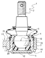
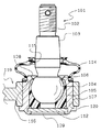
図1に示されるのは本発明の実施例によるボールジョイント1とアーム19との結合構造である。このボールジョイント1は、球状の球頭部4と球頭部4から突出する柄部3とからなるボールスタッド2と、ボールスタッド2の球頭部4を揺動回動自在に内包し一方に開口6を有する合成樹脂製のベアリング5と、ベアリング5を包持する略円筒状のハウジング7とを備える。ハウジング7には、一方にボールスタッド2の柄部3を突出させる小開口8、他方に端部内周に円盤状の閉止板12がかしめ固定される大開口9と、大開口9の外周に周状に形成されたつば部11とが形成されている。このハウジング7は、ボールスタッド2の球頭部4の球心を通る赤道線Xを挟んだ状態でハウジング7の外周面に2本の周状の溝10,10が軸線方向に間隔をおいて形成されている。また、ハウジング7の溝10,10軸線方向間には溝10,10と連続して溝間外径部72が形成され、溝間外径部72の外径はアーム19の穴部20の内径より小径に形成されている。また溝間外径部72の外径は溝10,10におけるハウジング7の外径より大径に形成されている。また14はダストカバーで、断面略L字状のL字環17が埋設されたダストカバー小開口部15がボールスタッド2の柄部3外周に、圧入環18が埋設されたダストカバー大開口部16がハウジング7の小開口8外周に各々装着される。
【0011】
また、アーム19は、ハウジング7のベアリング5の一方開口6側に形成される溝10と対向する位置に周状の溝21が形成される穴部20を有している。この穴部20にボールジョイント1のハウジング7が、穴部20の溝21とハウジング7の溝10が対向する状態で圧入固定されている。この穴部20の溝21とハウジング7の溝10とに一部が切りかかれたC状の抜け止めリング13が嵌装されている。この抜け止めリング13とハウジング7の外周面との間には隙間が形成されている。
【0012】
続いて上記ボールジョイント1とアーム19との結合方法を図2乃至図6を基に説明する。
【0013】
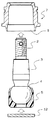
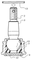
まず、ボールジョイント1の組立方法を説明する。まず図2に示す如く、ボールスタッド2の球頭部4にベアリング5の開口部6からベアリング5を嵌装する。次に図3に示す如く、ボールスタッド2の球頭部4にベアリング5を嵌装した状態でボールスタッド2の柄部3側からハウジング7の大開口9内周へ挿入してベアリング5をハウジング7内の所定の位置に配置し、続いて閉止板12をハウジング7の大開口9内周に挿入する。続いて、ハウジング7の大開口9端部を内周側にかしめ、図4に示す如く閉止板12を固定し、ボールスタッド2の柄部3側から抜け止めリング13をハウジング7の溝10に嵌装する。嵌装された抜け止めリング13は、図5に示す如く、ボールジョイント1のハウジング7の溝10から若干外周側に突出した状態で配置される。
【0014】
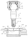
このボールジョイント1をアーム19の穴部20内に圧入する方法を図5及び図6に基づいて説明する。まず、図5に示す如く、アーム19の穴部20の一方開口側端部に治具50を当接させる。治具50はアーム19の穴部20と同径の一方開口52から他方開口53にむかって拡径するテーパー面51aが形成される治具穴部51を有しており、一方開口52側端部をアーム19の穴部20の一方開口側端部を当接させる。この治具50の治具穴部51の他方開口53からボールジョイント1をボールスタッド2の柄部3から圧入する。このとき、図6に示す如く、ボールジョイント1のハウジング7が治具50の治具穴部51に圧入されると、治具50のテーパー面51aに沿ってハウジング7の溝10に嵌装された抜け止めリング13が縮径される。この抜け止めリング13が縮径されてアーム19の穴部20内径と同径になった状態で、抜け止めリング13がアーム19の穴部20内に圧入される。ここで治具50は、ハウジング7のつば部11が治具穴部51の他方開口53側端部に当接する前に外周方向に二分割されてアーム19から離れる。続いて、ハウジング7の溝10がアーム19の穴部20の溝21と対向する位置に達すると、縮径されていた抜け止めリング13がもとの状態に拡径し、ハウジング7の穴部10とアーム19の穴部20の溝21とに渡った状態となり、図1に示される如くボールジョイント1とアーム19とが結合する。
【0015】
上記の如きボールジョイント1とアーム19との結合構造によれば、ハウジング7の外周面に形成された二つの溝10,10の軸線方向間に二つの溝10,10と連続して形成され、アーム19の穴部20の内径より小径で二つの溝10,10におけるハウジング7の外径より大径である溝間外径部72がアーム19の穴部20からの荷重を緩和するので、ボールスタッド2の球頭部4にかかる圧力が抑制される。
【0016】
また、抜け止めリング13がハウジング7の溝10と、ハウジング7の溝10と対向する位置に設けられるアーム19の穴部20の溝21に、ハウジング7の外周面との間に隙間が形成された状態で配置されているので、ハウジング7及びアーム19の抜け止めとなる。
【0017】
【発明の効果】
以上のように本発明のボールジョイントとアームとの結合構造によれば、球状の球頭部と球頭部から突出する柄部とよりなるボールスタッドと、ボールスタッドの球頭部を揺動回動自在に包持し、一方に開口を有するベアリングと、ベアリングを内包し、一方にボールスタッドの柄部を突出させる小開口を、他方に閉止板をかしめ固定する大開口を有するハウジングとよりなるボールジョイントと、ボールジョイントのハウジングが挿入される穴部を有するアームとの結合構造において、ボールジョイントのハウジング外周面には周状の溝が二つ形成され、ハウジングは二つの溝の軸線方向間に二つの溝と連続して溝間外径部が形成され、溝間外径部がアームの穴部の内径より小径であるとともに、溝間外径部は二つの溝におけるハウジングの外径より大径であり、且つ溝間外径部はボールスタッドの球頭部の球心を通る赤道線を有するため、ハウジング外周面に形成された溝及びアームの穴部の内径より小径の溝間外径部がアームの穴部からの荷重を緩和するので、ボールスタッドの球頭部にかかる圧力が抑制されるため、ボールスタッドの揺動にかかる作動トルクを低減することができる。
【0018】
また、アームの穴部の内周面に周状の溝が形成され、ボールジョイントのハウジングの溝及びアームの穴部の溝が対向する位置に設けられ、溝内にハウジングの外径より小径の内径、かつ、アームの内径より大径の外径を有する抜け止めリングが配置されており、溝内に配置された抜け止めリングとハウジングの外周面との間に隙間が形成されているので、ハウジング及びアームの抜け止めとなる。またハウジングの軸線方向長さを延ばすことなく、抜け止めリングを嵌装することができるので、ボールジョイントが大型化することを抜け止めリングが外側にある従来例と比べて防ぐことができる。
【図面の簡単な説明】
【図1】 本発明の実施例によるボールジョイントとアームとの結合構造を表す部分断面平面図である。
【図2】 本発明の実施例によるボールジョイントの製造の第一工程を表す部分断面平面図である。
【図3】 本発明の実施例によるボールジョイントの製造の第二工程を表す部分断面平面図である。
【図4】 本発明の実施例によるボールジョイントの製造の第三工程を表す部分断面平面図である。
【図5】 本発明の実施例によるボールジョイントとアームとの第一の結合工程を表す部分断面平面図である。
【図6】 本発明の実施例によるボールジョイントとアームとの第二の結合工程を表す部分断面平面図である。
【図7】 従来のボールジョイントとアームとの結合構造を表す部分断面平面図である。
【符号の説明】
2 ボールスタッド
3 柄部
4 球頭部
5 ベアリング
6 (ベアリング)開口
7 ハウジング
8 (ハウジング)小開口
9 (ハウジング)大開口
10 (ハウジング外周面の)溝
12 閉止板
13 抜け止めリング
19 アーム
20 穴部
21 (アーム内周面の)溝
72 溝間外径部
X 赤道線[0001]
[Industrial application fields]
The present invention relates to a joint structure of a ball joint and an arm used for, for example, a suspension device and a steering device of an automobile.
[0002]
[Prior art]
Conventionally, a connecting portion of a suspension device or a steering device of an automobile is often connected by coupling a ball joint and an arm. Such a joint structure between the ball joint and the arm is as shown in FIG. Such a
[0003]
The outer diameter of the
[0004]
[Problems to be solved by the invention]
In the joint structure of the
[0005]
Therefore, an object of the present invention is to solve the above-described problems and to provide a ball joint and arm coupling structure that reduces the operating torque required to swing the ball stud.
[0006]
[Means for Solving the Problems]
The configuration of the present invention is as follows.
[0007]
1. A ball stud consisting of a spherical ball head and a handle protruding from the ball head, a ball stud of the ball stud holding the ball head in a swingable manner, a bearing having an opening on one side, and a bearing included A ball joint comprising a housing having a small opening for projecting a ball stud handle on one side and a large opening for caulking and fixing a closing plate on the other; and an arm having a hole into which the ball joint housing is inserted. In the coupling structure, two circumferential grooves are formed on the outer peripheral surface of the ball joint housing, and the housing has an outer diameter portion between the grooves formed continuously between the two grooves in the axial direction of the two grooves. The outer diameter portion is smaller than the inner diameter of the hole portion of the arm, the outer diameter portion between the grooves is larger than the outer diameter of the housing in the two grooves, and the outer diameter portion between the grooves is the ball head of the ball stud. Ball Having equator line through.
[0008]
2. A circumferential groove is formed in the inner peripheral surface of the hole portion of the arm, and the groove of the ball joint housing and the groove of the arm hole portion are provided at opposing positions, and the inner diameter smaller than the outer diameter of the housing in the groove, In addition, a retaining ring having an outer diameter larger than the inner diameter of the arm is disposed, and when the ball joint and the arm are coupled, the retaining ring disposed in the groove and the outer peripheral surface of the housing. A gap is formed.
[0009]
【Example】
Embodiments of the present invention will be described below with reference to FIGS.
[0010]
FIG. 1 shows a coupling structure of a
[0011]
The
[0012]
Next, a method for connecting the
[0013]
First, a method for assembling the
[0014]
A method for press-fitting the ball joint 1 into the
[0015]
According to the coupling structure of the ball joint 1 and the
[0016]
Further , a clearance is formed between the
[0017]
【The invention's effect】
As described above, according to the coupling structure of the ball joint and the arm of the present invention, the ball stud including the spherical ball head and the handle protruding from the ball head, and the ball head of the ball stud are swung. It consists of a bearing that is movably held and has an opening on one side, a housing that encloses the bearing, a small opening that projects the ball stud handle on one side, and a large opening that crimps and fixes a closing plate on the other side. In the joint structure of the ball joint and the arm having the hole into which the ball joint housing is inserted, two circumferential grooves are formed on the outer peripheral surface of the ball joint housing, and the housing is located between the axial directions of the two grooves. intertrench outer diameter portion continuous with two grooves are formed in, together with the inter-groove outer diameter is smaller than the inner diameter of the hole in the arm, the groove between the outer diameter portion housing the two grooves A larger diameter than the outer diameter, and inter-groove outer diameter portion is to have a equatorial line through the spherical center of the spherical head of the ball stud, the smaller diameter than the inner diameter of the hole of the groove and the arm formed in the housing outer circumferential surface Since the outer diameter portion between the grooves alleviates the load from the hole portion of the arm, the pressure applied to the ball head of the ball stud is suppressed, so that the operating torque applied to the swing of the ball stud can be reduced.
[0018]
In addition, a circumferential groove is formed on the inner peripheral surface of the hole portion of the arm, and the groove of the ball joint housing and the groove of the arm hole portion are provided to face each other. The groove has a smaller diameter than the outer diameter of the housing. A retaining ring having an inner diameter and an outer diameter larger than the inner diameter of the arm is disposed, and a gap is formed between the retaining ring disposed in the groove and the outer peripheral surface of the housing . This prevents the housing and arm from coming off. In addition, since the retaining ring can be fitted without extending the axial length of the housing, it is possible to prevent the ball joint from becoming large compared to the conventional example in which the retaining ring is on the outside.
[Brief description of the drawings]
FIG. 1 is a partial cross-sectional plan view illustrating a coupling structure between a ball joint and an arm according to an embodiment of the present invention.
FIG. 2 is a partial cross-sectional plan view showing a first step of manufacturing a ball joint according to an embodiment of the present invention.
FIG. 3 is a partial sectional plan view showing a second step of manufacturing the ball joint according to the embodiment of the present invention.
FIG. 4 is a partial cross-sectional plan view showing a third step of manufacturing the ball joint according to the embodiment of the present invention.
FIG. 5 is a partial cross-sectional plan view showing a first coupling step between a ball joint and an arm according to an embodiment of the present invention.
FIG. 6 is a partial cross-sectional plan view showing a second coupling step between the ball joint and the arm according to the embodiment of the present invention.
FIG. 7 is a partial sectional plan view showing a conventional ball joint and arm coupling structure.
[Explanation of symbols]
2
Claims (2)
Priority Applications (1)
| Application Number | Priority Date | Filing Date | Title |
|---|---|---|---|
| JP2000213439A JP3973347B2 (en) | 2000-07-13 | 2000-07-13 | Connection structure of ball joint and arm |
Applications Claiming Priority (1)
| Application Number | Priority Date | Filing Date | Title |
|---|---|---|---|
| JP2000213439A JP3973347B2 (en) | 2000-07-13 | 2000-07-13 | Connection structure of ball joint and arm |
Publications (3)
| Publication Number | Publication Date |
|---|---|
| JP2002031126A JP2002031126A (en) | 2002-01-31 |
| JP2002031126A5 JP2002031126A5 (en) | 2004-10-14 |
| JP3973347B2 true JP3973347B2 (en) | 2007-09-12 |
Family
ID=18709191
Family Applications (1)
| Application Number | Title | Priority Date | Filing Date |
|---|---|---|---|
| JP2000213439A Expired - Fee Related JP3973347B2 (en) | 2000-07-13 | 2000-07-13 | Connection structure of ball joint and arm |
Country Status (1)
| Country | Link |
|---|---|
| JP (1) | JP3973347B2 (en) |
Families Citing this family (4)
| Publication number | Priority date | Publication date | Assignee | Title |
|---|---|---|---|---|
| WO2003056193A1 (en) * | 2001-12-25 | 2003-07-10 | Musashi Seimitsu Kogyo Kabushiki Kaisha | Structure for coupling ball joint and arm |
| JP4516882B2 (en) * | 2005-04-28 | 2010-08-04 | 武蔵精密工業株式会社 | Connection structure of ball joint and arm |
| CN113607256B (en) * | 2021-09-03 | 2024-12-31 | 中山佳维电子有限公司 | Portable electronic scale |
| CN115182925B (en) * | 2022-07-13 | 2024-04-05 | 十堰市盛凯汽车零部件有限公司 | Quick-insertion type flexible shaft ball connecting ball joint |
-
2000
- 2000-07-13 JP JP2000213439A patent/JP3973347B2/en not_active Expired - Fee Related
Also Published As
| Publication number | Publication date |
|---|---|
| JP2002031126A (en) | 2002-01-31 |
Similar Documents
| Publication | Publication Date | Title |
|---|---|---|
| US5836821A (en) | Elastic coupling for steering apparatus | |
| JPH01172610A (en) | Ball joint and manufacture thereof | |
| US7510344B2 (en) | Joint structure of ball joint and arm | |
| JP3973347B2 (en) | Connection structure of ball joint and arm | |
| JP2002031126A5 (en) | ||
| JP3960458B2 (en) | Ball joint | |
| JP4257731B2 (en) | Ball joint and manufacturing method thereof | |
| JP3150577B2 (en) | Ball joint | |
| JPH10318247A (en) | Ball joint | |
| JP3963374B2 (en) | Joint structure of joint member and arm | |
| JP3877265B2 (en) | Ball joint | |
| JP2004116546A (en) | Ball joint | |
| JP3812313B2 (en) | Cardan fitting | |
| JP2562330Y2 (en) | Ball joint seal structure | |
| JP2002372034A (en) | Connecting method of ball joint to arm | |
| JP2004044651A (en) | Connecting structure of ball joint and arm | |
| KR100414018B1 (en) | Ball joint structure for vehicle | |
| JP2002070831A (en) | Joint structure for ball joint and arm | |
| JPH0942268A (en) | Ball joint | |
| JP2004060839A (en) | Ball joint | |
| JP2002031125A (en) | Ball joint | |
| KR100434661B1 (en) | Ball joint structure for vehicle | |
| JPH07731Y2 (en) | Ball joint structure | |
| JPH0571433U (en) | Ball joint | |
| JPH0630521U (en) | Ball joint |
Legal Events
| Date | Code | Title | Description |
|---|---|---|---|
| A977 | Report on retrieval |
Free format text: JAPANESE INTERMEDIATE CODE: A971007 Effective date: 20060712 |
|
| A131 | Notification of reasons for refusal |
Free format text: JAPANESE INTERMEDIATE CODE: A131 Effective date: 20060721 |
|
| A521 | Written amendment |
Free format text: JAPANESE INTERMEDIATE CODE: A523 Effective date: 20060919 |
|
| A131 | Notification of reasons for refusal |
Free format text: JAPANESE INTERMEDIATE CODE: A131 Effective date: 20070119 |
|
| A521 | Written amendment |
Free format text: JAPANESE INTERMEDIATE CODE: A523 Effective date: 20070320 |
|
| TRDD | Decision of grant or rejection written | ||
| A01 | Written decision to grant a patent or to grant a registration (utility model) |
Free format text: JAPANESE INTERMEDIATE CODE: A01 Effective date: 20070612 |
|
| A61 | First payment of annual fees (during grant procedure) |
Free format text: JAPANESE INTERMEDIATE CODE: A61 Effective date: 20070612 |
|
| R150 | Certificate of patent or registration of utility model |
Free format text: JAPANESE INTERMEDIATE CODE: R150 |
|
| FPAY | Renewal fee payment (event date is renewal date of database) |
Free format text: PAYMENT UNTIL: 20100622 Year of fee payment: 3 |
|
| FPAY | Renewal fee payment (event date is renewal date of database) |
Free format text: PAYMENT UNTIL: 20110622 Year of fee payment: 4 |
|
| FPAY | Renewal fee payment (event date is renewal date of database) |
Free format text: PAYMENT UNTIL: 20130622 Year of fee payment: 6 |
|
| LAPS | Cancellation because of no payment of annual fees |