JP3972962B2 - Side-sliding maneuvering vehicle - Google Patents
Side-sliding maneuvering vehicle Download PDFInfo
- Publication number
- JP3972962B2 JP3972962B2 JP51390999A JP51390999A JP3972962B2 JP 3972962 B2 JP3972962 B2 JP 3972962B2 JP 51390999 A JP51390999 A JP 51390999A JP 51390999 A JP51390999 A JP 51390999A JP 3972962 B2 JP3972962 B2 JP 3972962B2
- Authority
- JP
- Japan
- Prior art keywords
- skid
- vehicle
- transmission case
- vehicle according
- ground
- Prior art date
- Legal status (The legal status is an assumption and is not a legal conclusion. Google has not performed a legal analysis and makes no representation as to the accuracy of the status listed.)
- Expired - Fee Related
Links
Images


Classifications
-
- E—FIXED CONSTRUCTIONS
- E02—HYDRAULIC ENGINEERING; FOUNDATIONS; SOIL SHIFTING
- E02F—DREDGING; SOIL-SHIFTING
- E02F9/00—Component parts of dredgers or soil-shifting machines, not restricted to one of the kinds covered by groups E02F3/00 - E02F7/00
- E02F9/08—Superstructures; Supports for superstructures
- E02F9/0808—Improving mounting or assembling, e.g. frame elements, disposition of all the components on the superstructures
-
- B—PERFORMING OPERATIONS; TRANSPORTING
- B60—VEHICLES IN GENERAL
- B60K—ARRANGEMENT OR MOUNTING OF PROPULSION UNITS OR OF TRANSMISSIONS IN VEHICLES; ARRANGEMENT OR MOUNTING OF PLURAL DIVERSE PRIME-MOVERS IN VEHICLES; AUXILIARY DRIVES FOR VEHICLES; INSTRUMENTATION OR DASHBOARDS FOR VEHICLES; ARRANGEMENTS IN CONNECTION WITH COOLING, AIR INTAKE, GAS EXHAUST OR FUEL SUPPLY OF PROPULSION UNITS IN VEHICLES
- B60K17/00—Arrangement or mounting of transmissions in vehicles
- B60K17/04—Arrangement or mounting of transmissions in vehicles characterised by arrangement, location, or kind of gearing
-
- B—PERFORMING OPERATIONS; TRANSPORTING
- B62—LAND VEHICLES FOR TRAVELLING OTHERWISE THAN ON RAILS
- B62D—MOTOR VEHICLES; TRAILERS
- B62D21/00—Understructures, i.e. chassis frame on which a vehicle body may be mounted
- B62D21/18—Understructures, i.e. chassis frame on which a vehicle body may be mounted characterised by the vehicle type and not provided for in groups B62D21/02 - B62D21/17
- B62D21/186—Understructures, i.e. chassis frame on which a vehicle body may be mounted characterised by the vehicle type and not provided for in groups B62D21/02 - B62D21/17 for building site vehicles or multi-purpose tractors
-
- B—PERFORMING OPERATIONS; TRANSPORTING
- B62—LAND VEHICLES FOR TRAVELLING OTHERWISE THAN ON RAILS
- B62D—MOTOR VEHICLES; TRAILERS
- B62D49/00—Tractors
- B62D49/02—Tractors modified to take lifting devices
-
- E—FIXED CONSTRUCTIONS
- E02—HYDRAULIC ENGINEERING; FOUNDATIONS; SOIL SHIFTING
- E02F—DREDGING; SOIL-SHIFTING
- E02F3/00—Dredgers; Soil-shifting machines
- E02F3/04—Dredgers; Soil-shifting machines mechanically-driven
- E02F3/28—Dredgers; Soil-shifting machines mechanically-driven with digging tools mounted on a dipper- or bucket-arm, i.e. there is either one arm or a pair of arms, e.g. dippers, buckets
- E02F3/283—Dredgers; Soil-shifting machines mechanically-driven with digging tools mounted on a dipper- or bucket-arm, i.e. there is either one arm or a pair of arms, e.g. dippers, buckets with a single arm pivoted directly on the chassis
-
- E—FIXED CONSTRUCTIONS
- E02—HYDRAULIC ENGINEERING; FOUNDATIONS; SOIL SHIFTING
- E02F—DREDGING; SOIL-SHIFTING
- E02F9/00—Component parts of dredgers or soil-shifting machines, not restricted to one of the kinds covered by groups E02F3/00 - E02F7/00
- E02F9/16—Cabins, platforms, or the like, for drivers
-
- B—PERFORMING OPERATIONS; TRANSPORTING
- B60—VEHICLES IN GENERAL
- B60K—ARRANGEMENT OR MOUNTING OF PROPULSION UNITS OR OF TRANSMISSIONS IN VEHICLES; ARRANGEMENT OR MOUNTING OF PLURAL DIVERSE PRIME-MOVERS IN VEHICLES; AUXILIARY DRIVES FOR VEHICLES; INSTRUMENTATION OR DASHBOARDS FOR VEHICLES; ARRANGEMENTS IN CONNECTION WITH COOLING, AIR INTAKE, GAS EXHAUST OR FUEL SUPPLY OF PROPULSION UNITS IN VEHICLES
- B60K17/00—Arrangement or mounting of transmissions in vehicles
- B60K17/04—Arrangement or mounting of transmissions in vehicles characterised by arrangement, location, or kind of gearing
- B60K17/10—Arrangement or mounting of transmissions in vehicles characterised by arrangement, location, or kind of gearing of fluid gearing
- B60K17/105—Units comprising at least a part of the gearing and a torque-transmitting axle, e.g. transaxles
-
- B—PERFORMING OPERATIONS; TRANSPORTING
- B60—VEHICLES IN GENERAL
- B60K—ARRANGEMENT OR MOUNTING OF PROPULSION UNITS OR OF TRANSMISSIONS IN VEHICLES; ARRANGEMENT OR MOUNTING OF PLURAL DIVERSE PRIME-MOVERS IN VEHICLES; AUXILIARY DRIVES FOR VEHICLES; INSTRUMENTATION OR DASHBOARDS FOR VEHICLES; ARRANGEMENTS IN CONNECTION WITH COOLING, AIR INTAKE, GAS EXHAUST OR FUEL SUPPLY OF PROPULSION UNITS IN VEHICLES
- B60K17/00—Arrangement or mounting of transmissions in vehicles
- B60K17/34—Arrangement or mounting of transmissions in vehicles for driving both front and rear wheels, e.g. four wheel drive vehicles
- B60K17/342—Arrangement or mounting of transmissions in vehicles for driving both front and rear wheels, e.g. four wheel drive vehicles having a longitudinal, endless element, e.g. belt or chain, for transmitting drive to wheels
-
- B—PERFORMING OPERATIONS; TRANSPORTING
- B60—VEHICLES IN GENERAL
- B60K—ARRANGEMENT OR MOUNTING OF PROPULSION UNITS OR OF TRANSMISSIONS IN VEHICLES; ARRANGEMENT OR MOUNTING OF PLURAL DIVERSE PRIME-MOVERS IN VEHICLES; AUXILIARY DRIVES FOR VEHICLES; INSTRUMENTATION OR DASHBOARDS FOR VEHICLES; ARRANGEMENTS IN CONNECTION WITH COOLING, AIR INTAKE, GAS EXHAUST OR FUEL SUPPLY OF PROPULSION UNITS IN VEHICLES
- B60K17/00—Arrangement or mounting of transmissions in vehicles
- B60K17/34—Arrangement or mounting of transmissions in vehicles for driving both front and rear wheels, e.g. four wheel drive vehicles
- B60K17/356—Arrangement or mounting of transmissions in vehicles for driving both front and rear wheels, e.g. four wheel drive vehicles having fluid or electric motor, for driving one or more wheels
Description
〔技術分野〕
本発明は、本体、オペレータ室およびブーム構体からなり、前記本体が前方端および後方端を有しかつそれぞれ車両の対向側に配置された第1および第2の地面に係合可能な推進手段を備え、かつそのさい前記第1および第2の地面に係合可能な推進手段が車両の他方の側の推進手段から独立して車両の一方の側に配設された推進手段を駆動することにより車両を推進かつ操縦するために第1および第2の伝動手段によって駆動され、前記ブーム構体が、その外方端において、前記ブーム構体に荷捌き器具を接続するための接続手段を有しており、そして前記ブーム構体の内方端が、上昇位置と、前記ブーム構体が前記オペレータ室の一方の側にのみ沿って前方に延びかつ前記荷捌き器具が本体の前方端の前方に配置される下降位置との間の運動のために、前記本体の後方端に隣接して、本体に枢着される、横滑り操縦積み込み車両(スキッド・ステアリング・ローダー)に関するものである。
〔従来の技術〕
特定された種類の横滑り操縦積み込み車両はアメリカ合衆国特許第4,055,262号に開示されている。その車両は第1および第2の伝動手段が配置されかつオペレータが車両に着座するときオペレータがトランスミッションケース(トランスミッションケース)手段に跨がる必要がある単一のトランスミッションケース手段を有している。
加えて、ブーム構体は、下降位置にあるとき車両の前方の前の間にそこで延びている荷捌き器具を備えた車両の反対側に配置された2つの間隔を置いた持ち上げアーム構体からなっている。オペレータ室へのアクセスは器具を取り扱うことによりオペレータ室の前方により得られる。
ヨーロッパ特許第0,443,830B号は、また、特定された種類の横滑り操縦積み込み車両を開示している。その車両には、2つの横方向に間隔が置かれたトランスミッションケース手段があり、各トランスミッションケース手段は、オペレータがその間に配置される車両の反対側に離して配置される単一の伝動装置手段を含んでいる。
加えて、車両はオペレータ室の一方の側にのみ沿って前方に延びる単一の持ち上げアーム構体を有している。かかる車両においては、アメリカ合衆国特許第4,055,262号の前方のアクセスが回避されるけれども、オペレータが車両の側からオペレータ室へアクセスすることができるので、オペレータはトランスミッションケース手段の1方を取り扱う必要がある。加えて、後方に対する視界は反対側で本体に枢着されるように本体の後方を横切って横方向に延びる持ち上げアーム構体用の枢動部材の存在により部分的に妨げられる。
〔発明が解決しようとする課題〕
本発明の目的は、それにより上述した問題が克服されるかまたは減少される特定された種類の横滑り操縦積み込み車両を提供することにある。
〔課題を解決するための手段〕
本発明によれば、上記した目的は、前記第1および第2伝動手段が、トランスミッションケース手段の内部に設けられており、該トランスミッションケース手段が、車両の一方の側にのみ配置されていることを特徴とする横滑り操縦積み込み車両を提供することにより達成される。
第1伝動手段はトランスミッションケース手段の一方の側から突出しかつ第1の地面に係合可能な推進手段に接続される第1駆動部材からなりそして第2の伝動手段はトランスミッションケース手段の反対側から突出しかつ第2の地面に係合可能な推進手段に駆動接続されるように車両を横切って横方向に延びる第2駆動部材からなっている。
第1伝動手段は第1前方駆動部材および第1後方駆動部材からなることができ、各駆動部材はトランスミッションケース手段の一方の側から突出しかつ第1の地面に係合可能な推進手段に駆動接続されそして第2の伝動手段がトランスミッションケース手段の反対側から突出しかつ車両を横切って横方向に延びそして第2の地面に係合可能な推進手段に駆動接続される第2前方駆動部材および第2後方駆動部材からなっている。
各駆動部材は、駆動要素により、好ましくは駆動ループによって駆動されるそれぞれの被動輪に駆動接続される。
トランスミッションケース手段は1対の間隔を置いた、好ましくは平行な、側壁からなることができ、それらの側壁の間に第1および第2の伝動手段が配置される。
側壁は頂部および底部壁によってかつ対向端壁によって接合され得る。
側壁は車両の一方の側に配置されかつその上方領域に、下降位置にあるときオペレータ室の一方の側のみに沿って前方に延びる単一の持ち上げアーム構体からなるブーム構体用の枢着手段を設けている直立体の側壁からなっている延長部分を備えている。
各地面に係合可能な推進手段は2つの地面に係合可能な車輪または1対の案内輪のまわりに引きずられる無端軌道からなることができる。
地面に係合可能な車輪からなるとき、地面に係合可能な推進手段は、第1の地面に係合可能な推進手段の各地面に係合可能な推進車輪が、本体上に取り付けられる短軸ハウジング部材内で、回転軸線のまわりに回転し得るように、収納される短軸の外方端に支持されるように配置され、前記短軸は、第1伝動手段の駆動部材を設けるか、またはそれに駆動接続されている。
第2の地面ら係合可能な推進手段の各第2の地面に係合可能な推進車輪は、本体に取り付けられる細長い軸ハウジング部材内で、回転軸線のまわりに回転し得るように、収納される細長い軸の外方端に支持され得る。
短軸ハウジング部材はトランスミッションケース手段の1壁に取り付けられてもよい。
細長い軸ハウジング部材は1端に隣接してトランスミッションケース手段の反対の壁の開口にかつ本体の反対側に設けられた開口または他の装置に取り付けられ得る。
本体は一方の側でトランスミッションケース手段をかつ本体の反対側で対向端間に配置された本体の領域にアクセスするように第2の前方および後方駆動部材の間に下方に延びる凹所を有する反対の側壁を備えることができる。
トランスミッションケース手段および本体の反対側壁は本体の前方および後方に横方向に延びる部分によって相互に接続され得る。後方に横方向に延びる部分はその後方に隣接している側部分間にエンジン室を設けるように本体の後方から前方に配置されることができる。
前記後方に横方向に延びる部分は前記後方被動部分の前方に配置され得る。
各駆動ループはローラチェーンのごときチェーンからなりそして駆動要素および被動輪はチェーンとの係合用のスプロケットからなることができる。
代替的に、各駆動ループは歯付きまたは歯を持たないベルトからなることができそして駆動要素および被動輪は協働プーリからなっても良い。
駆動要素はモータの出力軸に、またはモータの出力軸によって駆動される軸に支持されても良い。
各モータはトランスミッションケース手段の互いに同一の側に取り付けられ得る。
各モータは、トランスミッションケース手段内に配置された駆動要素を備えた箱手段から外方に配置されるようにトランスミッションケース手段の外方、または内方壁に取り付けられ得る。
本発明を実施する車両は、したがって、オペレータがトランスミッションケース手段を取り扱う必要なしに車両の他の側からのオペレータ室への容易なアクセスを設ける。車両は、トランスミッションケース手段の延長部分が伝動車へ伝達されるような積み込み機からの入力を許容するので、前述されたように単一のタワーを設けることにより改良された構造的一体性を備える。
加えて、単一のタワー直立体は車両の後方を横切って横方向に延びる枢動部材を回避することによって車両の後方に対する改善された視界を提供する。
トランスミッションケース手段の同一の内方壁上への各モータの備えは改善された保護の利点を有し、車輪のタイヤの間の侵入がないので最小にされたホイールベースが可能になり、使用が容易でかつホースランが容易である。
本発明の例を、以下で、添付図面を参照して説明する。
〔発明を実施するための最良の形態〕
次に図面を参照すると、横滑り操縦積み込み車両10は前方端12および後方端13を有している本体11からなっている。
本体11は前方の地面係合可能な車輪15および後方の地面係合可能な車輪16からなっている第1の地面係合可能な推進手段14、および本体の反対側で、同様に後輪18および前輪19からなっている第2の地面に係合可能な推進手段17を備えている。車両10は同一速度で4輪すべてを駆動することによって、または、車両を操縦するために、第2の地面に係合可能な手段19の車輪17,18より異なる速度および/または方向において第1の地面に係合可能な推進手段14の車輪15,16を駆動することによって、前方にまたは後方に向って真っ直ぐに推進することができる。かかる横滑り操縦積み込み機は高度の操縦性を有しかつ横滑り操縦を容易にし、そして、例えば、特に地面に係合可能な推進手段14及び17の中間に位置する垂直中心軸線のまわりに回転可能とするために、前後の輪間距離(ホイールベース)は、本実施例においては、所望ならば、ホイールベースは左右の車輪が成す軌道幅と同一または所望ならばそれより長くすることができるけれども、車輪軌道幅より僅かに短く作られている。
車輪15,16はベアリング22aによって短軸ハウジング部材22内に回転可能に支持されかつ第1駆動要素を構成する短軸21に相対回転不能に固定されるハブ20上に支持されている。
車輪18,19は、短軸21より長い長軸24のための管状軸ハウジング25内に回転可能に取り付けられかつ第2駆動要素を構成する長軸24に相対回転不能に固定されるハブ23上に支持されている。
次に、とくに第4図ないし第6図を参照して、本体11は、一方の側で、略平らな外方側壁31および略平らな内方側壁32からなる単一のトランスミッションケース手段30からなっている。内方及び外方側壁31,32は、底壁33および傾斜頂部壁34によってともに接続され、この傾斜頂部壁34は外方端縁で外方壁31に接続されかつ内側の上方端縁で内方壁32と一体の内方にかつ上方に傾斜されたさらに他の部分35に接続される。この例において、側壁は略平行であるが、所望ならば、それらは平行でなくてもよい。
延長部分36はさらに他の部分35と一体でありかつ上方に突出しそしてオペレータ室39の側フレーム38の後方部材用の取り付け具37aを設けられた内方に向けられたフランジ37を備えている。側フレーム38の前方部材およびオペレータ室の対向側フレーム40の前方部材は符号37bおよび40aで、その前方端12で本体を横切って横方向に延びる本体の前方壁部分42の内側に曲げられたフランジ41にそれぞれ固定される。フレーム40の後方部材は第2の横方向に延びる壁50に取り付けられる。フレーム38および40は頂部壁46を備えかつガラス窓が付けられおよび/または所望されるような通常の方法において他の部分を備えてもよい。
前方壁部分42は、オペレータの座席および持ち上げアーム構体の駆動および運転用の通常の制御盤が設けられる本体の内部キャビティ45にアクセスするように切り欠かれた部分44を備える本体の対向側壁43に接続される。
第2の横方向に延びている壁50が、トランスミッションケース手段30の内方側壁32と、本体の一方の側上のさらに他の部分35及び延長部分36と本体の前方および後方端12,13の中間に配置された位置において、対向側壁43との間に設けられる。それはオペレータ室39と車両のエンジンとの間に隔壁を形成している。トランスミッションケース手段30の内方側壁32およびさらに他の部分35及び延長部分36は、横方向壁50の後方に延びかつ側壁43の延長部分51とともに、オペレータ室の後ろにエンジン室53を設けている。延長部分51は、対向側壁43に対して平行であるが、その外方に向かって、ホイールアーチ53を形成している横方向に延びる壁52によって間隔が置かれる。前方ホイールアーチ54はさらに他の中間壁55によって形成されている。壁52と55はネジ山付き固定具によって側壁43に固定される。
トランスミッションケース手段30の外方側壁31の延長部分60は直立体またはタワー61の1つの外方部材を設ける一方、内方壁32の延長部分62はタワー61の内方側壁を設ける。延長部分60は外方側壁31に対して平行であるが、その外方に向かって、壁31および延長部分60と一体である傾斜された部分60aによって間隔が置かれている。タワー61は横方向に延びる部材60によって補強されかつさらに部材64および65によって補強されている。タワー61の上方端に隣接して設けられるのは、1対の取り付けブッシュ66であり、これらの取り付けブッシュによって単一の持ち上げアーム構体67が、内方端で、その後方端13に隣接して車両10の本体11に枢着される。持ち上げアーム構体67はオペレータ室39の一方の側68に隣接して配置される。持ち上げアーム構体67は、この持ち上げアーム構体67用の枢軸を設けるために前記ブッシュ66内に受容される枢軸ピン70用の図示してない受容手段を有している。
前方端において、持ち上げアーム構体67は器具支持部材71を有しており、この部材71は持ち上げアーム構体67の前方端72から突出しかつその前方に本体12の前方端を横切って延びそして本体11の前方端12の前方位置に支持される荷捌き器具73を有している。本例において、器具73は地ならしバケットであるが、所望ならば、他の荷捌き器具73が1組のフォークのごとく設けられ得る。
持ち上げアーム構体67は略正方形断面の管状構成として形成されそして持ち上げアーム構体の内方端69aから外方端72に向かって略直線的に延びる大きな部分74および外方端72で終端するように大きな部分71に対して略下方にかつ前方に延びそして器具支持手段71を備えた小さな部分74aからなっている。
油圧式持ち上げアーム75は、タワーの外方壁60と合流するトランスミッションケース手段30の外方壁31の補強された部分76と、部分74と75との間の接合領域において持ち上げアーム構体67に溶接されるブラケット77との間に枢動可能に接続される。各端部での持ち上げアーム75の枢動接続はそれぞれの板およびブラケットに設けられた開口に溶接されかつその反対端でラムに設けられた開口を貫通する枢動ブッシュに取り付けられる枢動ピン78からなる。加えて、押し込みラム80が持ち上げアーム構体69のカンチレバーに配置された枢動ピン81と器具支持体71の枢動ピン取り付け開口81aとの間に設けられる。
次に、第3図および第7図を参照して、トランスミッションケース手段30はそれに第1および第2伝動手段T1,T2を有しており、これらの伝動手段によって第1および第2推進手段14,17が駆動される。駆動部材を構成する短軸21はそれぞれ、それに堅固に接続された第1の前方および後方被動輪90,91を備えている。被動輪90,91は、それぞれ駆動ループ92,93によって、第1の流体静力学的駆動モータ96の出力軸に支持されるそれぞれの駆動要素94,95に接続される。
駆動部材24は同様に、モータ96の下に配置される第2の流体静力学的駆動モータ103の出力軸に支持されたそれぞれの駆動要素101,102にそれぞれの駆動ループ99,100によって接続される、第2の、前方および後方被動輪97,98を備えている。もちろん、所望ならば、モータ103はモータ96の上方に配置されてもよい。
所望ならば、駆動要素94,95,101,102はモータの出力軸から離れた軸に設けられるがそれによって駆動される得る。
第1伝動手段T1は第1駆動部材21、駆動輪90,91、駆動ループ92,93および駆動要素94,95からなっている。第2伝動手段T2は第2駆動部材24、駆動輪97,98、駆動ループ99.100および駆動要素101,102からなっている。
本実施例において、被動輪および駆動要素はスプロケットからなりそのまわりにローラチェーンを含む駆動ループが引きずられる。所望ならば、しかしながら、駆動ループは歯付きまたは歯を持たないベルトのごとき他の手段からなっても良く、その場合の手段においてそれらは適宜に形作られた協働駆動要素および被動輪のまわりに引きずられる。
複数の短軸ハウジング22は各々が箱手段30が回転され得るように箱手段30にボルトで止められるように配置されそして短軸の回転軸線は、ループ92,93の緊張が調整され得るようにヨーロッパ特許第0,443,830号に記載された方法と同様な方法においてハウジングの回転軸線に対して同中心的になっている。
ループ99,100の緊張は、ループと連係する駆動モータ103をループ箱手段の内方部材32に対して垂直に上下動することにより調整される。
所望ならば、2つの地面に係合可能な車輪からなる各地面に係合可能な推進手段に代えて、各地面に係合可能な推進手段が1対の案内輪のまわりに係合される無端軌道からなってもよい。案内輪の少なくとも1つはハブ20または23またはそれと同様な部材によって支持されかつそのまわりに引きずられる無端軌道を有することができる。この箱手段において、所望ならば、案内手段の1つのみが関連の駆動要素94,95または101,102から案内輪90,91または97,98によって駆動され得る。
さらに、代替的に、両者の場合に、所望ならば、駆動部材21,24は、駆動ループ以外の手段、例えばギヤまたは関連のモータからギヤと駆動軸の組み合わせによって駆動され得る。
第3図に符号Eで総括的に示されるエンジンは通常の方法においてエンジン室50に設けられそして通常の方法において前述されたモータ96,103を駆動するために制御手段によって作動し得る1またはそれ以上の油圧ポンプに接続されている。
上述した例において車両の構成要素は溶接によって普通に接合されるが、所望ならば、固定具のごとき他の手段によって共に接合され得る。構成要素が互いに一体であるように前述されたが、所望ならば、それらは溶接によってまたは他の適宜な方法において接合される別個の要素により作られ得る。
上述した例において、持ち上げアーム構体およびトランスミッションケース手段は車両の前方に面しているとき車両の右手側に設けられているごとく記載されたけれども、所望ならば、車両の形状は、持ち上げアーム構体およびトランスミッションケース手段が前方に面しているとき車両の左手側に設けられかつ切り欠きが車両の右手側に設けられた切り欠き44に対応しているように逆にされ得る。
前述されたトランスミッションケース手段は、第1および第2トランスミッションケース手段がその間に配置される2つの間隔を置いた平行な側壁のみを有している単一のトランスミッションケースを含んでいた。しかしながら、所望ならば、トランスミッションケース手段は、各対の間にトランスミッションケースの一方のみ配置される1対の間隔を置いた、好ましくは平行な、側壁を各々有している2つの別個のトランスミッションケースからなってもよい。別個のトランスミッションケースは所望のごとく構成されそして互いに一体にまたは所望のごとく接続されることができる。さらに代替的にトランスミッションケースは、前記第1または第2トランスミッションケース手段の1つがその各々に配置される2つの別個の室を形成するように中間壁がそれらの間に配置される2つの間隔を置いた、好ましくは平行な、側壁からなることができる。所望ならば他の形状のトランスミッションケース手段が設けられ得る。
特別な形状においてまたは開示された機能を実施するための手段、または開示された結果を達成するための方法または工程、または適切なような、物質または組成物の等級またはグループによって、前記で開示された特徴、または以下の請求の範囲、または添付図面は、かかる特徴を個々にまたはかかる特徴の組み合わせにおいて、本発明を種々の形状において実施するのに利用され得る。
【図面の簡単な説明】
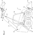
第1図は、本発明を実施する横滑り操縦積み込み車両を示す斜視図、
第2図は、第1図の車両の側面図、
第3図は、第1図の車両であるが、明瞭にするために省略された部分を有する平面図、
第4図は、第1図の車両の本体部分であるが、明瞭にするために省略された部分を有する斜視図、
第5図は、第4図の線5−5の斜視図、
第6図は、第4図と同様であるが、車両本体の反対側から取られた斜視図、
第7図は、明瞭にするために省略された部分を有する第3図の線7−7の断片的な断面図である。〔Technical field〕
The present invention comprises a propulsion means comprising a main body , an operator room, and a boom structure, wherein the main body has a front end and a rear end, and is respectively engageable with first and second grounds disposed on opposite sides of the vehicle. provided, and that engageable propulsion means to drive the other independent of the propulsion means on the side one promotion means disposed on the side of the vehicle of the vehicle thereof the first and second ground Driven by first and second transmission means for propelling and maneuvering the vehicle, wherein the boom structure has connecting means for connecting a handling device to the boom structure at its outer end. Contact is, inner end of the boom structure and its includes a raised position, the front of the forward end of the boom assembly extends forwardly I along only one side of the operator compartment and the material handling implement main body Between the lowered position For dynamic, adjacent the rearward end of the body, is pivotally attached to the main body, to a side slip maneuver loading vehicle (skid steering loader).
[Conventional technology]
A specified type of skid-loading vehicle is disclosed in U.S. Pat. No. 4,055,262. The vehicle has a single transmission case means in which the first and second transmission means are arranged and the operator needs to straddle the transmission case (transmission case) means when the operator sits on the vehicle.
In addition, the boom assembly comprises two spaced lifting arm assemblies disposed on the opposite side of the vehicle with a handling device extending there between the front front of the vehicle when in the lowered position. Yes. Access to the operator room is gained from the front of the operator room by handling the instrument.
European Patent No. 0,443,830B also discloses a specified type of skid-loading vehicle. The vehicle has two laterally spaced transmission case means, each transmission case means being a single transmission means located on the opposite side of the vehicle between which the operator is located Is included.
In addition, the vehicle has a single lifting arm structure that extends forward along only one side of the operator room. In such a vehicle, although the forward access of US Pat. No. 4,055,262 is avoided, the operator can access one of the transmission case means because the operator can access the operator room from the vehicle side. There is a need. In addition, visibility to the rear is partially hindered by the presence of a pivoting member for the lifting arm assembly that extends laterally across the rear of the body so that it is pivotally mounted on the opposite side.
[Problems to be Solved by the Invention]
It is an object of the present invention to provide a specified type of skid-loading vehicle by which the above mentioned problems are overcome or reduced.
[Means for solving the problems]
According to the present invention , the above-mentioned object is that the first and second transmission means are provided inside the transmission case means, and the transmission case means is disposed only on one side of the vehicle. It is achieved by Rukoto to provide a lateral slip maneuver loading vehicle according to claim.
And it consists of a first transmission means is a first drive member is connected to one projecting from the side and the first engageable propulsion means on the ground of the transmission case Hand stage second transmission means the opposite of the transmission case Hand stage And a second drive member extending laterally across the vehicle so as to drive-connect to a propulsion means projecting from the side and engageable with the second ground.
The first transmission means may consist of a first forward drive member and the first rear driving member, each drive member projecting from one side of the transmission case hand stages and driven in a first engageable propulsion means on the ground connected and second forward drive member second transmission means is drivingly connected to the extending and engageable propulsion means to the second ground laterally across the projecting and the vehicle from the opposite side of the transmission case hand stage and It consists of a second rear drive member.
Each drive member is drivingly connected to a respective driven wheel driven by a drive element, preferably by a drive loop.
Transmission case Hand stage spaced pair preferably parallel, can be made from the side wall, the first and second transmission means are disposed between those side walls.
The side walls may be joined by top and bottom walls and by opposing end walls.
The side wall is located on one side of the vehicle and in the upper region there is a pivoting means for the boom structure consisting of a single lifting arm structure extending forward only along one side of the operator compartment when in the lowered position. It has an extended portion consisting of a straight solid side wall.
The propulsion means engageable with each ground can consist of an endless track dragged around two ground-engageable wheels or a pair of guide wheels.
When comprised of wheels that are engageable with the ground, the propulsion means that is engageable with the ground is the short of the propulsion wheels that are engageable with each ground of the propulsion means being engageable with the first ground. In the shaft housing member, it is arranged to be supported on the outer end of the short shaft stored so that it can rotate around the rotation axis, and the short shaft is provided with a drive member for the first transmission means. Or connected to drive.
A propulsion wheel engageable with each second ground of the propulsion means engageable from the second ground is housed such that it can rotate about an axis of rotation within an elongated shaft housing member attached to the body. Can be supported on the outer end of the elongate shaft.
Minor housing member may be attached to the first wall of the transmission case hand stage.
Elongated shaft housing member may be attached to an opening or other device on the opposite side of the body and adjacent one end to the opening of the opposite wall of the transmission case hand stage.
The body has a recess extending downwardly between the second front and rear driving member to access to the region of the deployed main body between the opposite end on the opposite side of the body and a transmission case hand stage on one side Opposite sidewalls can be provided.
Transmission case Hand stage and opposite side walls of the body may be interconnected by a portion extending laterally to the front and rear of the body. The rearwardly extending portion can be disposed from the rear to the front of the main body so as to provide an engine compartment between the side portions adjacent to the rear.
The rearwardly extending portion may be disposed in front of the rear driven portion.
Each drive loop may consist of a chain, such as a roller chain, and the drive elements and driven wheels may consist of sprockets for engagement with the chain.
Alternatively, each drive loop can consist of a toothed or non-toothed belt and the drive element and driven wheel can consist of cooperating pulleys.
The drive element may be supported on the output shaft of the motor or on a shaft driven by the output shaft of the motor.
Each motor may be mounted on the same side to each other of the transmission case hand stage.
Each motor may be mounted outside or inside wall of the transmission case Hand stage so as to be disposed outwardly from the box means having a drive element disposed within the transmission case hand stage.
Vehicle for implementing the present invention, therefore, the operator is provided with easy access to the operator compartment from the other side of the vehicle without having to handle the transmission case hand stage. Vehicle, because the extension of the transmission case hand stage is allowed to enter from the palletizer as transmitted to the transmission wheel, the structural integrity of which is improved by providing a single tower as described previously Prepare.
In addition, a single tower cube provides an improved view of the rear of the vehicle by avoiding pivoting members that extend laterally across the rear of the vehicle.
Has the advantage of improved protection is provided for each motor onto the same inner wall of the transmission case hand stage, since there is no penetration between the wheel tire enables wheelbase which is minimized, using Is easy and the hose run is easy.
Examples of the present invention will be described below with reference to the accompanying drawings.
[Best Mode for Carrying Out the Invention]
Referring now to the drawings, a skid steer loading
The
Next, in particular with reference to Figure 4 through Figure 6, the
The
Extension of the
At the front end, the
Lift
Hydraulic lifting arm 75 includes a reinforcing
Next, with reference to FIGS. 3 and FIG. 7, the transmission case Hand stage 30 has a first and second transmission means T1, T2 thereto, the first and second propulsion means by these transmission means 14 and 17 are driven. Each of the
The
If desired, the
The first transmission means T1 includes a
In this embodiment, the driven wheel and the drive element are sprockets around which a drive loop including a roller chain is dragged. If desired, however, the drive loop may consist of other means, such as a toothed or toothless belt, in which case they are arranged around appropriately shaped cooperating drive elements and driven wheels. Dragged.
The plurality of
The tension of the
If desired, instead of propulsion means engageable with each ground consisting of two ground engageable wheels, propulsion means engageable with each ground are engaged around a pair of guide wheels. It may consist of endless orbits. At least one of the guide wheels may have an endless track supported by and dragged about the
Further alternatively, in both cases, if desired, the
The engine, indicated generally by the symbol E in FIG. 3, is provided in the
In the example described above, the vehicle components are commonly joined by welding, but can be joined together by other means such as a fixture if desired. While the components have been described above as being integral with each other, if desired, they can be made by separate elements joined by welding or in any other suitable manner.
In the example described above, but the arm assembly and the transmission case Hand stage lifting has been described as provided on the right hand side of the vehicle when facing the front of the vehicle, if desired, the shape of the vehicle, the lifting arm assembly and the transmission case hand stages may be reversed as to correspond to the notches 44 provided on the left hand side of the vehicle and notches are provided on the right hand side of the vehicle when facing forwardly .
Above it has been the transmission case hands stage, first and second transmission case hand stage contained the single transmission case having only parallel side walls two spaced disposed therebetween. However, if desired, the transmission case Hand stage spaced pair disposed only one of the transmission case between each pair, preferably parallel, the two separate having each a side wall Transmission it may be the case whether the lines cover. The separate transmission cases can be configured as desired and connected together or as desired. Further alternatively the transmission case, the first or second one of the transmission case Hand stage two intervals intermediate wall to form two separate chambers arranged in each of which is disposed between them It can consist of side walls, preferably parallel. If desired transmission case hand stages of other shapes may be provided.
As disclosed above, in a particular form or by means for performing the disclosed function, or method or process for achieving the disclosed results, or, as appropriate, the grade or group of substances or compositions. The features, or the following claims, or the accompanying drawings, may be used to implement the invention in various forms, either individually or in combination of such features.
[Brief description of the drawings]
FIG. 1 is a perspective view showing a skid loading vehicle for carrying out the present invention,
FIG. 2 is a side view of the vehicle of FIG.
FIG. 3 is a plan view of the vehicle of FIG. 1 but with parts omitted for clarity;
FIG. 4 is a perspective view of the vehicle body portion of FIG. 1 but with portions omitted for clarity;
FIG. 5 is a perspective view taken along line 5-5 of FIG.
FIG. 6 is the same as FIG. 4, but is a perspective view taken from the opposite side of the vehicle body,
FIG. 7 is a fragmentary cross-sectional view of line 7-7 of FIG. 3 with parts omitted for clarity.
Claims (26)
前記第1および第2伝動手段が、トランスミッションケース手段の内部に設けられており、該トランスミッションケース手段が、車両の一方の側にのみ配置されていることを特徴とする横滑り操縦積み込み車両。A main body , an operator room, and a boom structure, the main body having a front end and a rear end, and having propulsion means engageable with first and second grounds disposed on opposite sides of the vehicle, respectively propel the vehicle by driving again said first and second one promotion means disposed on the side of the vehicle independently of the propulsion means on the other side of the engageable propulsion means the vehicle on the ground and is driven by the first and second transmission means to steer, the boom assembly is in its outer end, Propelled by one connecting means for connecting the material handling implement to the boom assembly, its the inner end of the boom structure comprises a raised position, the boom structure is one of extending forwardly I along only the side and the material handling implement of the operator chamber is arranged in front of the forward end of the body and For movement between lowered positions , Adjacent the rearward end of the body, is pivotally attached to the main body, the side slip maneuver loading vehicle,
A skid loading vehicle characterized in that the first and second transmission means are provided inside a transmission case means, and the transmission case means is disposed only on one side of the vehicle.
Applications Claiming Priority (5)
| Application Number | Priority Date | Filing Date | Title |
|---|---|---|---|
| GBGB9717892.5A GB9717892D0 (en) | 1997-08-23 | 1997-08-23 | Skid steer loader vehicle |
| GB9717892.5 | 1997-08-23 | ||
| GB9802685A GB2328429B (en) | 1997-08-23 | 1998-02-10 | Skid steer loader vehicle |
| GB9802685.9 | 1998-02-10 | ||
| PCT/EP1998/005263 WO1999010606A1 (en) | 1997-08-23 | 1998-08-19 | Skid steer loader vehicle |
Publications (2)
| Publication Number | Publication Date |
|---|---|
| JP2001509225A JP2001509225A (en) | 2001-07-10 |
| JP3972962B2 true JP3972962B2 (en) | 2007-09-05 |
Family
ID=26312114
Family Applications (1)
| Application Number | Title | Priority Date | Filing Date |
|---|---|---|---|
| JP51390999A Expired - Fee Related JP3972962B2 (en) | 1997-08-23 | 1998-08-19 | Side-sliding maneuvering vehicle |
Country Status (7)
| Country | Link |
|---|---|
| EP (1) | EP0932729B1 (en) |
| JP (1) | JP3972962B2 (en) |
| CA (1) | CA2269535C (en) |
| DE (1) | DE69809877T2 (en) |
| ES (1) | ES2191338T3 (en) |
| FR (1) | FR2767507B1 (en) |
| WO (1) | WO1999010606A1 (en) |
Families Citing this family (6)
| Publication number | Priority date | Publication date | Assignee | Title |
|---|---|---|---|---|
| ATE341668T1 (en) * | 2001-03-29 | 2006-10-15 | Komatsu Utility Europe Spa | CARRYING FRAME FOR A WHEEL LOADER |
| EP1712115A1 (en) * | 2005-04-13 | 2006-10-18 | Merlo Project S.r.l. | Lifting vehicle with a support frame with closed section |
| GB2477760B (en) | 2010-02-11 | 2015-06-03 | Bamford Excavators Ltd | Working machine |
| GB2477759B (en) | 2010-02-11 | 2015-02-18 | Bamford Excavators Ltd | Working machine |
| KR20230152183A (en) * | 2017-04-19 | 2023-11-02 | 클라크 이큅먼트 컴파니 | Loader frame |
| CN109435687B (en) * | 2018-10-29 | 2021-10-15 | 苏州履坦智能科技有限公司 | Novel multistage chain transmission and steering mechanism for wheeled vehicle |
Family Cites Families (5)
| Publication number | Priority date | Publication date | Assignee | Title |
|---|---|---|---|---|
| US2257772A (en) * | 1932-04-07 | 1941-10-07 | Austin M Wolf | Motor vehicle propulsion |
| US3810517A (en) * | 1971-12-30 | 1974-05-14 | Sperry Rand Corp | Loader drive |
| US4055262A (en) | 1976-02-02 | 1977-10-25 | Clark Equipment Company | Loader main frame for skid steer loader |
| CA2036552A1 (en) | 1990-02-21 | 1991-08-22 | Joseph C. Bamford | Skid steer vehicle |
| WO1993005974A1 (en) * | 1991-09-20 | 1993-04-01 | Power Research And Development Pty. Ltd. | Removable drive system for a skid steer loader |
-
1998
- 1998-03-13 FR FR9803145A patent/FR2767507B1/en not_active Expired - Lifetime
- 1998-08-19 CA CA002269535A patent/CA2269535C/en not_active Expired - Lifetime
- 1998-08-19 ES ES98946379T patent/ES2191338T3/en not_active Expired - Lifetime
- 1998-08-19 DE DE69809877T patent/DE69809877T2/en not_active Expired - Lifetime
- 1998-08-19 JP JP51390999A patent/JP3972962B2/en not_active Expired - Fee Related
- 1998-08-19 WO PCT/EP1998/005263 patent/WO1999010606A1/en active IP Right Grant
- 1998-08-19 EP EP98946379A patent/EP0932729B1/en not_active Expired - Lifetime
Also Published As
| Publication number | Publication date |
|---|---|
| FR2767507A1 (en) | 1999-02-26 |
| CA2269535A1 (en) | 1999-03-04 |
| FR2767507B1 (en) | 1999-12-31 |
| JP2001509225A (en) | 2001-07-10 |
| EP0932729B1 (en) | 2002-12-04 |
| ES2191338T3 (en) | 2003-09-01 |
| CA2269535C (en) | 2006-11-28 |
| DE69809877T2 (en) | 2003-04-24 |
| WO1999010606A1 (en) | 1999-03-04 |
| DE69809877D1 (en) | 2003-01-16 |
| EP0932729A1 (en) | 1999-08-04 |
Similar Documents
| Publication | Publication Date | Title |
|---|---|---|
| US5964567A (en) | Skid steer loader vehicle | |
| FR2477494A1 (en) | VEHICLE ALL TERRAINS WITH TWO UNITS MU BY HYDRAULIC MOTORS | |
| JP3935793B2 (en) | Mower | |
| JP3972962B2 (en) | Side-sliding maneuvering vehicle | |
| JP3383539B2 (en) | Walking mower | |
| JP3364649B2 (en) | Traveling device for walking type management machine | |
| JP3095666B2 (en) | Gear case for work vehicle | |
| JP3767190B2 (en) | Grass mower discharging device of mower | |
| US3731757A (en) | Steering mechanisms | |
| JP2007118908A (en) | Small crawler type tractor | |
| KR101451623B1 (en) | Vehicle movement driving device for onion harvester | |
| JP3509921B2 (en) | Passenger management machine | |
| JP2781457B2 (en) | Crawler type traveling device | |
| JP3541058B2 (en) | Self-propelled root vegetable harvester | |
| EP0551404A1 (en) | Wheeled vehicle. | |
| JP3540070B2 (en) | Root cropper | |
| JP3458919B2 (en) | Operation section of self-propelled root vegetable harvester | |
| JP3652229B2 (en) | Work vehicle | |
| JPH0769228A (en) | Wheel steering device in riding-type agricultural machine | |
| JP3540069B2 (en) | Root crop harvester control device | |
| JP2001163273A (en) | Traveling device for walking type tending machine | |
| JP2002360005A (en) | Traveling apparatus of walking type tending machine | |
| JP2007118909A (en) | Agricultural tractor | |
| JPH10117546A (en) | Mower | |
| JPH0577910A (en) | Stacker crane |
Legal Events
| Date | Code | Title | Description |
|---|---|---|---|
| A621 | Written request for application examination |
Free format text: JAPANESE INTERMEDIATE CODE: A621 Effective date: 20050713 |
|
| A131 | Notification of reasons for refusal |
Free format text: JAPANESE INTERMEDIATE CODE: A131 Effective date: 20060815 |
|
| A601 | Written request for extension of time |
Free format text: JAPANESE INTERMEDIATE CODE: A601 Effective date: 20061115 |
|
| A602 | Written permission of extension of time |
Free format text: JAPANESE INTERMEDIATE CODE: A602 Effective date: 20070105 |
|
| A521 | Written amendment |
Free format text: JAPANESE INTERMEDIATE CODE: A523 Effective date: 20070215 |
|
| TRDD | Decision of grant or rejection written | ||
| A01 | Written decision to grant a patent or to grant a registration (utility model) |
Free format text: JAPANESE INTERMEDIATE CODE: A01 Effective date: 20070410 |
|
| A01 | Written decision to grant a patent or to grant a registration (utility model) |
Free format text: JAPANESE INTERMEDIATE CODE: A01 Effective date: 20070508 |
|
| A61 | First payment of annual fees (during grant procedure) |
Free format text: JAPANESE INTERMEDIATE CODE: A61 Effective date: 20070605 |
|
| R150 | Certificate of patent or registration of utility model |
Free format text: JAPANESE INTERMEDIATE CODE: R150 |
|
| FPAY | Renewal fee payment (event date is renewal date of database) |
Free format text: PAYMENT UNTIL: 20100622 Year of fee payment: 3 |
|
| FPAY | Renewal fee payment (event date is renewal date of database) |
Free format text: PAYMENT UNTIL: 20110622 Year of fee payment: 4 |
|
| FPAY | Renewal fee payment (event date is renewal date of database) |
Free format text: PAYMENT UNTIL: 20120622 Year of fee payment: 5 |
|
| FPAY | Renewal fee payment (event date is renewal date of database) |
Free format text: PAYMENT UNTIL: 20130622 Year of fee payment: 6 |
|
| R250 | Receipt of annual fees |
Free format text: JAPANESE INTERMEDIATE CODE: R250 |
|
| R250 | Receipt of annual fees |
Free format text: JAPANESE INTERMEDIATE CODE: R250 |
|
| R250 | Receipt of annual fees |
Free format text: JAPANESE INTERMEDIATE CODE: R250 |
|
| R250 | Receipt of annual fees |
Free format text: JAPANESE INTERMEDIATE CODE: R250 |
|
| R250 | Receipt of annual fees |
Free format text: JAPANESE INTERMEDIATE CODE: R250 |
|
| LAPS | Cancellation because of no payment of annual fees |