JP3971448B2 - Drawing apparatus and drawing method - Google Patents
Drawing apparatus and drawing method Download PDFInfo
- Publication number
- JP3971448B2 JP3971448B2 JP2006301059A JP2006301059A JP3971448B2 JP 3971448 B2 JP3971448 B2 JP 3971448B2 JP 2006301059 A JP2006301059 A JP 2006301059A JP 2006301059 A JP2006301059 A JP 2006301059A JP 3971448 B2 JP3971448 B2 JP 3971448B2
- Authority
- JP
- Japan
- Prior art keywords
- texture
- polygon
- unit
- data
- unit graphic
- Prior art date
- Legal status (The legal status is an assumption and is not a legal conclusion. Google has not performed a legal analysis and makes no representation as to the accuracy of the status listed.)
- Expired - Fee Related
Links
Images


Description
本発明は、コンピュータを用いた映像機器であるグラフィックコンピュータ、特殊効果
装置、ビデオゲーム機等に用いられる描画装置及び描画方法に関する。
The present invention relates to a drawing apparatus and a drawing method used for a graphic computer, a special effect device, a video game machine, and the like, which are video equipment using a computer.
従来、家庭用TVゲーム機やパーソナルコンピュータあるいはグラフィックコンピュー
タなどにおいて、テレビジョン受像機やモニタ受像機あるいは陰極線管(CRT:Cathod
e Ray Tube)ディスプレイ装置などに出力して表示する画像のデータすなわち表示出力画
像データを生成する画像生成装置では、央演算処理装置(CPU: Central Processing
Unit)とフレームバッファの間に専用の描画装置を設けることにより、高速処理を可能に
している。
2. Description of the Related Art Conventionally, television receivers, monitor receivers, or cathode ray tubes (CRT: Cathod) in home video game consoles, personal computers, graphic computers, and the like.
e Ray Tube) In an image generation device that generates image data to be output and displayed on a display device, that is, display output image data, a central processing unit (CPU)
High-speed processing is possible by providing a dedicated drawing device between the unit) and the frame buffer.
すなわち、上記画像生成装置において、CPU側では、画像を生成する際に、直接フレ
ームバッファをアクセスするのではなく、座標変換やクリッピング、光源計算等のジオメ
トリ処理を行い、3角形や4角形などの基本的な単位図形(ポリゴン)の組み合わせとし
て3次元モデルを定義して3次元画像を描画するための描画命令を作成し、その描画命令
を描画装置に送る。例えば、3次元のオブジェクトを表示する場合は、オブジェクトを複
数のポリゴンに分解して、各ポリゴン対応する描画命令をCPUから描画装置に転送する
。そして、描画装置は、CPUから送られてきた描画命令を解釈して、頂点の色データと
奥行きを示すZ値から、ポリゴンを構成する全ての画素の色とZ値を考慮して、画素デー
タをフレームバッファに書き込むレンダリング処理を行い、フレームバッファに図形を描
画する。なお、上記Z値は、視点からの奥行き方向の距離を示す情報である。
That is, in the above image generation apparatus, when generating an image, the CPU does not directly access the frame buffer, but performs geometric processing such as coordinate conversion, clipping, and light source calculation, so that a triangle, a quadrangle, etc. A three-dimensional model is defined as a combination of basic unit figures (polygons), a drawing command for drawing a three-dimensional image is created, and the drawing command is sent to the drawing device. For example, when displaying a three-dimensional object, the object is decomposed into a plurality of polygons, and a drawing command corresponding to each polygon is transferred from the CPU to the drawing apparatus. Then, the drawing apparatus interprets the drawing command sent from the CPU, and considers the color and Z value of all the pixels constituting the polygon from the color data of the vertex and the Z value indicating the depth. Is rendered in the frame buffer, and the figure is drawn in the frame buffer. The Z value is information indicating the distance in the depth direction from the viewpoint.
例えば、上記画像生成装置において、3次元のオブジェクトを表示する場合は、オブジ
ェクトを複数のポリゴンに分解して、各ポリゴンに対応する描画命令をCPUから描画装
置に転送する。この際に、オブジェクトをより実際に近く表現するために、テクスチャマ
ッピングやミップマッピングと呼ばれる手法が採用されている。さらに、色変換データを
記憶したカラールックアップテーブル(CLUT: Color Lock Up Table)を介して画像
の色データを変換することにより、表示色を変化させる手法も広く知られている。
For example, when displaying a three-dimensional object in the image generation apparatus, the object is decomposed into a plurality of polygons, and a drawing command corresponding to each polygon is transferred from the CPU to the drawing apparatus. At this time, a technique called texture mapping or mip mapping is employed in order to more closely represent the object. Furthermore, a technique for changing the display color by converting color data of an image via a color look-up table (CLUT) that stores color conversion data is also widely known.
ここで、テクスチャマッピングとは、テクスチャソース画像として別に用意された2次
元画像(絵柄)すなわちテクスチャパターンを物体を構成するポリゴンの表面に張り付け
る技術である。また、ミップマッピングは、3次元モデルに近づいたり、それから遠ざか
った場合に、ポリゴンの張り付ける絵柄が不自然にならないように画素データを補間する
ようにしたテクスチャマッピングの手法の1つである。
Here, texture mapping is a technique for pasting a two-dimensional image (picture) prepared separately as a texture source image, that is, a texture pattern, onto the surface of a polygon constituting the object. In addition, mip mapping is one of texture mapping techniques in which pixel data is interpolated so that a pattern pasted by a polygon does not become unnatural when approaching or moving away from a three-dimensional model.
ところで、画像の描画速度は、描画エンジンにおける各ポリゴンに対するテクスチャマ
ッピングやミップマッピング等の処理速度に依存する。また、画像の描画速度は、描画エ
ンジンからフレームバッファへの書き込み速度に影響され、フレームバッファのアクセス
速度が遅いと描画速度が低下することになる。従って、描画速度を高めるために高価な高
速メモリを大容量のフレームバッファに用いることはシステムの価格の高騰につながり、
安価なダイナミックランダムアクセスメモリ(DRAM:Dynamic Random Access Memory
)等のメモリを用いるとシステムの描画速度が遅くなる、という欠点がある。
Incidentally, the drawing speed of an image depends on processing speeds such as texture mapping and mip mapping for each polygon in the drawing engine. The image drawing speed is affected by the writing speed from the drawing engine to the frame buffer. If the frame buffer access speed is low, the drawing speed decreases. Therefore, using an expensive high-speed memory in a large-capacity frame buffer to increase the drawing speed leads to a system price increase.
Inexpensive Dynamic Random Access Memory (DRAM)
) And the like, there is a drawback that the drawing speed of the system becomes slow.
そこで、本発明は、上述したような実情に鑑みてなされたものであり、次のような目的
を有する。
Therefore, the present invention has been made in view of the above-described circumstances, and has the following objects.
すなわち、本発明の目的は、安価なDRAM等のメモリをフレームバッファとして用い
ても、描画速度を高速に維持できるような描画装置及び描画方法を提供することにある。
That is, an object of the present invention is to provide a drawing apparatus and a drawing method capable of maintaining a high drawing speed even when an inexpensive memory such as a DRAM is used as a frame buffer.
また、本発明に他の目的は、単位図形の組合せにより定義された画像モデルを描画する
ための描画命令に基づいて、描画手段により、単位図形の全ての画素の画素データを効率
よく生成して、画像メモリに描画することができる描画装置及び描画方法を提供すること
にある。
Another object of the present invention is to efficiently generate pixel data of all pixels of a unit graphic by a drawing means based on a drawing command for drawing an image model defined by a combination of unit graphics. Another object of the present invention is to provide a drawing apparatus and a drawing method capable of drawing in an image memory.
また、本発明に他の目的は、単位図形の組合せにより定義された画像モデルを描画する
ための描画命令に基づいて、描画手段により、テクスチャキャッシュ内のテクスチャデー
タに基づいてテクスチャマッピグ処理を確実且つ効率よく行うことができる描画装置及び
描画方法を提供することにある。
Another object of the present invention is to ensure that the texture mapping process is performed based on the texture data in the texture cache by the rendering means based on the rendering command for rendering the image model defined by the combination of unit graphics. Another object of the present invention is to provide a drawing apparatus and a drawing method that can be performed efficiently.
また、本発明に他の目的は、単位図形の組合せにより定義された画像モデルを描画する
ための描画命令に基づいて、描画手段により処理するポリゴンの大きさすなわち画素数を
均等化することができる描画装置及び描画方法を提供することにある。
Another object of the present invention is to equalize the size of polygons, that is, the number of pixels processed by the drawing means, based on a drawing command for drawing an image model defined by a combination of unit graphics. To provide a drawing apparatus and a drawing method.
また、本発明に他の目的は、単位図形の組合せにより定義された画像モデルを描画する
ための描画命令に基づいて、描画手段により、テクスチャキャッシュ内のテクスチャデー
タに基づいてテクスチャの歪みの少ない状態でテクスチャマッピグ処理を行うことができ
る描画装置及び描画方法を提供することにある。
Another object of the present invention is to provide a state in which the texture is less distorted based on the texture data in the texture cache by the rendering means based on the rendering command for rendering the image model defined by the combination of unit graphics. It is an object to provide a drawing apparatus and a drawing method capable of performing texture mapping processing.
また、本発明に他の目的は、単位図形の組合せにより定義された画像モデルを描画する
ための描画命令に基づいて、描画手段により、ミップマップテクスチャデータに基づいて
ミップマッピング処理を効率よく行うことができる描画装置及び描画方法を提供すること
にある。
Another object of the present invention is to efficiently perform mip mapping processing based on mip map texture data by a drawing unit based on a drawing command for drawing an image model defined by a combination of unit graphics. It is an object of the present invention to provide a drawing apparatus and a drawing method capable of performing the above.
また、本発明に他の目的は、前処理手段と描画手段とをパイプラインで構成して、単位
図形の組合せにより定義された画像モデルを描画するための描画命令に基づいて、上記描
画手段により、効率よく高速描画処理を行うことができる描画装置及び描画方法を提供す
ることにある。
Another object of the present invention is to construct the preprocessing means and the drawing means by a pipeline and use the drawing means based on a drawing command for drawing an image model defined by a combination of unit graphics. Another object of the present invention is to provide a drawing apparatus and a drawing method capable of efficiently performing high-speed drawing processing.
さらに、本発明に他の目的は、描画命令に基づくポリゴンをピクセルインターリーブ処
理に適した形状の複数の新たなポリゴンに分割して、描画手段いより、フレームバッファ
を効率よくアクセスして高速の描画処理を行うことができる描画装置及び描画方法を提供
することにある。
Furthermore, another object of the present invention is to divide a polygon based on a drawing command into a plurality of new polygons having a shape suitable for pixel interleaving processing, and efficiently access the frame buffer from the drawing means to perform high-speed drawing. An object is to provide a drawing apparatus and a drawing method capable of performing processing.
本発明は、単位図形の組合せにより定義された画像モデルを描画するための描画命令に
基づいて、描画手段により、単位図形の全ての画素の画素データを生成して、画像メモリ
に描画する描画装置及び描画方法であって、前処理手段によりを単位図形を複数に分割す
ることを特徴とする。
The present invention relates to a drawing apparatus for generating pixel data of all the pixels of a unit graphic by a drawing means based on a drawing command for drawing an image model defined by a combination of unit graphics, and drawing the image data in an image memory. And a drawing method, wherein the unit graphic is divided into a plurality of pieces by the preprocessing means.
本発明に係る描画装置及び描画方法では、例えば、単位図形が上記描画手段におけるテ
クスチャキャシュ内に収まるか否かを判定する判定手段による判定結果に基づいて、分割
した新たな単位図形が上記テクスチャキャシュ内に収まるように上記描画命令に基づく単
位図形を複数に分割する。
In the drawing apparatus and the drawing method according to the present invention, for example, a new divided unit graphic is added to the texture cache based on the determination result by the determination unit that determines whether the unit graphic is within the texture cache in the drawing unit. The unit graphic based on the drawing command is divided into a plurality of pieces so as to be contained within.
また、本発明に係る描画装置及び描画方法では、例えば、単位図形内の画素数が規定値
以下であるか否かを判定する判定手段による判定結果に基づいて、分割した新たな単位図
形内の画素数が上記規定値以下となるように上記描画命令に基づく単位図形を2次元空間
で複数に分割する。
In the drawing apparatus and the drawing method according to the present invention, for example, based on the determination result by the determination unit that determines whether or not the number of pixels in the unit graphic is equal to or less than a specified value, A unit graphic based on the drawing command is divided into a plurality of two-dimensional spaces so that the number of pixels is equal to or less than the specified value.
また、本発明に係る描画装置及び描画方法では、例えば、上記描画命令に基づく単位図
形を3次元空間で複数に分割する。
In the drawing apparatus and the drawing method according to the present invention, for example, the unit graphic based on the drawing command is divided into a plurality of pieces in a three-dimensional space.
また、本発明に係る描画装置及び描画方法では、例えば、単位図形が参照するミップマ
ップテクスチャの参照範囲を判定する判定手段による判定結果に基づい、分割した新たな
単位図形が参照するミップマップテクスチャの参照範囲が所定範囲となるように上記描画
命令に基づく単位図形を3次元空間で複数に分割する。
In the drawing device and the drawing method according to the present invention, for example, based on the determination result by the determining unit that determines the reference range of the mipmap texture referred to by the unit graphic, the new divided unit graphic refers to the mipmap texture. The unit graphic based on the drawing command is divided into a plurality of pieces in the three-dimensional space so that the reference range becomes a predetermined range.
また、本発明に係る描画装置及び描画方法では、例えば、単位図形内の画素数が規定値
以下であるか否かを判定する判定手段による判定結果に基づいて、分割した新たな単位図
形内の画素数が上記規定値以下となるように上記描画命令に基づく単位図形を上記判定手
段による判定結果に基づいて3次元空間で複数に分割する。
In the drawing apparatus and the drawing method according to the present invention, for example, based on the determination result by the determination unit that determines whether or not the number of pixels in the unit graphic is equal to or less than a specified value, The unit graphic based on the drawing command is divided into a plurality of parts in a three-dimensional space based on the determination result by the determination means so that the number of pixels is equal to or less than the specified value.
また、本発明に係る描画装置及び描画方法では、例えば、単位図形に対する上記描画手
段による描画処理時間を予測して判定する判定手段による判定結果に基づいて、当該前処
理手段による前処理時間と上記描画手段による描画処理時間がバランスするように上記描
画命令に基づく単位図形を複数に分割する。
In the drawing apparatus and the drawing method according to the present invention, for example, based on the determination result by the determination unit that predicts and determines the drawing processing time by the drawing unit for the unit graphic, the preprocessing time by the preprocessing unit and the above The unit graphic based on the drawing command is divided into a plurality of pieces so that the drawing processing time by the drawing means is balanced.
さらに、本発明に係る描画装置及び描画方法では、例えば、単位図形の形状を判定する
判定手段による判定結果に基づいて、分割した新たな単位図形が所定形状に近づくように
上記描画命令に基づく単位図形を複数に分割する。
Furthermore, in the drawing apparatus and the drawing method according to the present invention, for example, based on the determination result by the determination unit that determines the shape of the unit graphic, the unit based on the drawing command so that the new divided unit graphic approaches the predetermined shape. Divide the figure into multiple pieces.
以上のように、本発明に係る描画装置及び描画方法では、単位図形を複数に分割する前
処理手段を備えるので、描画手段により処理するのに適した状態に単位図形を分割するこ
とができ、単位図形の組合せにより定義された画像モデルを描画するための描画命令に基
づいて、上記描画手段により、単位図形の全ての画素の画素データを効率よく生成して、
画像メモリに描画することができる。
As described above, in the drawing apparatus and the drawing method according to the present invention, since the pre-processing unit that divides the unit graphic into a plurality of units is provided, the unit graphic can be divided into a state suitable for processing by the drawing unit, Based on a drawing command for drawing an image model defined by a combination of unit graphics, the drawing means efficiently generates pixel data of all the pixels of the unit graphic,
Can be drawn to image memory.
また、本発明に係る描画装置及び描画方法では、単位図形が描画手段におけるテクスチ
ャキャシュ内に収まるか否かを判定する判定手段による判定結果に基づいて、前処理手段
により、分割した新たな単位図形が上記テクスチャキャシュ内に収まるように描画命令に
基づく単位図形を複数に分割するので、描画手段において、テクスチャキャッシュ内のテ
クスチャデータに基づいてテクスチャマッピグ処理を確実且つ効率よく行うことができる
。
In the drawing apparatus and the drawing method according to the present invention, the new unit graphic divided by the preprocessing unit based on the determination result by the determining unit that determines whether the unit graphic is within the texture cache in the drawing unit. Since the unit graphic based on the rendering command is divided into a plurality of units so that the image is contained in the texture cache, the texture mapping process can be reliably and efficiently performed on the rendering unit based on the texture data in the texture cache.
また、本発明に係る描画装置及び描画方法では、単位図形内の画素数が規定値以下であ
るか否かを判定する判定手段による判定結果に基づいて、前処理手段により、分割した新
たな単位図形内の画素数が上記規定値以下となるように上記描画命令に基づく単位図形を
2次元空間で複数に分割するので、描画手段において処理するポリゴンの大きさすなわち
画素数を均等化することができる。
In the drawing device and the drawing method according to the present invention, the new unit divided by the preprocessing unit based on the determination result by the determining unit that determines whether or not the number of pixels in the unit graphic is equal to or less than the specified value. Since the unit graphic based on the drawing command is divided into a plurality of two-dimensional spaces so that the number of pixels in the graphic is equal to or less than the specified value, it is possible to equalize the size of the polygon processed in the drawing means, that is, the number of pixels. it can.
また、本発明に係る描画装置及び描画方法では、単位図形内の画素数が規定値以下であ
るか否かを判定する判定手段による判定結果に基づいて、前処理手段により、分割した新
たな単位図形内の画素数が上記規定値以下となるように上記描画命令に基づく単位図形を
3次元空間で複数に分割するので、例えばテクスチャキャッシュ内のテクスチャデータに
基づいてテクスチャの歪みの少ない状態でテクスチャマッピグ処理を行うことができる。
In the drawing device and the drawing method according to the present invention, the new unit divided by the preprocessing unit based on the determination result by the determining unit that determines whether or not the number of pixels in the unit graphic is equal to or less than the specified value. Since the unit graphic based on the drawing command is divided into a plurality of three-dimensional spaces so that the number of pixels in the graphic is equal to or less than the specified value, for example, the texture can be generated with less texture distortion based on the texture data in the texture cache. Mapping processing can be performed.
また、本発明に係る描画装置及び描画方法では、単位図形が参照するミップマップテク
スチャの参照範囲を判定する判定手段による判定結果に基づいて、前処理手段により、分
割した新たな単位図形が参照するミップマップテクスチャの参照範囲が所定範囲となるよ
うに描画命令に基づく単位図形を3次元空間で複数に分割するので、ミップマップテクス
チャデータに基づいてミップマッピング処理を効率よく行うことができる。
In the drawing apparatus and drawing method according to the present invention, the new divided unit graphic is referred to by the preprocessing unit based on the determination result by the determination unit that determines the reference range of the mipmap texture referred to by the unit graphic. Since the unit graphic based on the drawing command is divided into a plurality of pieces in the three-dimensional space so that the reference range of the mipmap texture becomes a predetermined range, the mipmap processing can be efficiently performed based on the mipmap texture data.
また、本発明に係る描画装置及び描画方法では、単位図形に対する描画手段による描画
処理時間を予測して判定する判定手段による判定結果に基づいて、前処理手段による前処
理時間と上記描画手段による描画処理時間がバランスするように描画命令に基づく単位図
形を複数に分割するので、上記前処理手段と描画手段の各処理時間のバランスを保つこと
ができ、上記前処理手段と描画手段とをパイプラインで構成して効率よく高速描画処理を
行うことができる。
In the drawing apparatus and drawing method according to the present invention, the preprocessing time by the preprocessing means and the drawing by the drawing means are determined based on the determination result by the determination means that predicts and determines the drawing processing time by the drawing means for the unit graphic. Since the unit graphic based on the drawing command is divided into a plurality of units so that the processing time is balanced, the processing time of the preprocessing unit and the drawing unit can be kept balanced, and the preprocessing unit and the drawing unit are connected to the pipeline. And can perform high-speed drawing processing efficiently.
さらに、本発明に係る描画装置及び描画方法では、単位図形の形状を判定する判定手段
判定結果に基づいて、前処理手段により、分割した新たな単位図形が所定形状に近づくよ
うに描画命令に基づく単位図形を複数に分割するので、上記描画命令に基づくポリゴンを
ピクセルインターリーブ処理に適した形状の複数の新たなポリゴンに分割することができ
る。これにより、描画手段で、フレームバッファを効率よくアクセスして高速の描画処理
を行うことができる。
Further, in the drawing apparatus and the drawing method according to the present invention, based on the determination unit determination result for determining the shape of the unit graphic, the preprocessing unit is based on the drawing command so that the new divided unit graphic approaches the predetermined shape. Since the unit graphic is divided into a plurality of pieces, the polygon based on the drawing command can be divided into a plurality of new polygons having a shape suitable for the pixel interleaving process. Thus, the drawing means can efficiently access the frame buffer and perform high-speed drawing processing.
以下、本発明の好ましい実施の形態について、図面を参照しながら説明する。 Hereinafter, preferred embodiments of the present invention will be described with reference to the drawings.
本発明に係る描画装置は、例えば図1に示すような構成のビデオゲーム装置に適用され
る。本発明に係る描画方法は、このビデオゲーム装置において実施される。
The drawing apparatus according to the present invention is applied to, for example, a video game apparatus configured as shown in FIG. The drawing method according to the present invention is implemented in this video game apparatus.
このビデオゲーム装置は、例えば光学ディスク等の補助記憶装置に記憶されているゲー
ムプログラムを読み出して実行することにより、使用者からの指示に応じてゲームを行う
ものであって、図1に示すような構成を有している。
This video game apparatus plays a game in accordance with an instruction from a user by reading out and executing a game program stored in an auxiliary storage device such as an optical disk, for example, as shown in FIG. It has a configuration.
すなわち、このビデオゲーム装置は、2種類のバスすなわち、メインバス1とサブバス
2を備える。
That is, this video game apparatus includes two types of buses, that is, a
上記メインバス1とサブバス2は、バスコントローラ10を介して接続されている。
The
そして、上記メインバス1には、マイクロプロセッサなどからなる主中央演算処理装置
(メインCPU:Central Processing Unit)11、ランダムアクセスメモリ(RAM:Ra
ndom Access Memory)からなる主記憶装置(メインメモリ)12、主ダイナミックメモリ
アクセスメモリコントローラ(メインDMAC: Dinamic Memory Access Controller)
13、MPEGデコーダ(MDEC:MPEG Decorder)14及び画像処理装置(GPU:
Graphic Processing Unit)15が接続されている。また、上記サブバス2には、マイク
ロプロセッサなどからなる副中央演算処理装置(サブCPU: Central Processing Unit
)21、ランダムアクセスメモリ(RAM: Random Access Memory)からなる副記憶装置
(サブメモリ)22、副ダイナミックメモリアクセスメモリコントローラ(サブDMAC
:Dinamic Memory Access Controller)23、オペレーティングシステム等のプログラム
が格納されたリードオンリーメモリ(ROM: Read Only Memory)24、音声処理装置
(SPU: Sound Processing Unit)25、通信制御部(ATM: Asynchronous Transi
mission mode)26、補助記憶装置27及び入力デバイス28が接続されている。
The
main memory device (main memory) 12 consisting of ndom access memory), main dynamic memory access memory controller (main DMAC: main memory access controller)
13. MPEG decoder (MDEC: MPEG Decorder) 14 and image processing device (GPU:
Graphic Processing Unit) 15 is connected. The
) 21, a secondary storage device (sub memory) 22 composed of a random access memory (RAM), a sub dynamic memory access memory controller (sub DMAC)
: Dinamic Memory Access Controller) 23, Read Only Memory (ROM) 24 in which a program such as an operating system is stored, Sound Processing Unit (SPU) 25, Communication Control Unit (ATM: Asynchronous Transi)
mission mode) 26,
上記バスコントローラ10は、メインバス1とサブバス2との間のスイッチングを行う
上記メインバス1上のデバイスであって、初期状態ではオープンになっている。
The
また、上記メインCPU11は、上記メインメモリ12上のプログラムで動作する上記
メインバス1上のデバイスである。このメインCPU11は、起動時には上記バスコント
ローラ10がオープンになっていることにより、上記サブバス2上のROM24からブー
トプログラムを読み込んで実行し、補助記憶装置27からアプリケーションプログラム及
び必要なデータを上記メインメモリ12や上記サブバス2上のデバイスにロードする。こ
のメインCPU11には、座標変換等の処理を行うジオミトリトランスファエンジン(G
TE: Geometry TransferEngine )17が搭載されている。上記GTE17は、例えば
複数の演算を並列に実行する並列演算機構を備え、上記メインCPU11からの演算要求
に応じて座標変換,光源計算,行列あるいはベクトルなどの演算を高速に行う。そして、
上記メインCPU11は、上記GTE17による演算結果に基づいて3角形や4角形など
の基本的な単位図形(ポリゴン)の組み合わせとして3次元モデルを定義して3次元画像
を描画するための各ポリゴンに対応する描画命令を作成し、この描画命令をパケット化し
てコマンドパケットとして上記GPU15に送る。
The main CPU 11 is a device on the
TE: Geometry TransferEngine) 17 is installed. The
The main CPU 11 defines a three-dimensional model as a combination of basic unit graphics (polygons) such as a triangle and a quadrangle based on the calculation result by the
また、上記メインDMAC13は、メインバス1上のデバイスを対象とするDMA転送
の制御等を行う上記メインバス1上のデバイスである。このメインDMAC13は、上記
バスコントローラ10がオープンになっているときにはサブバス2上のデバイスも対象と
する。
The main DMAC 13 is a device on the
また、上記GPU15は、レンダリングプロセッサとして機能する上記メインバス1上
のデバイスである。このGPU15は、メインCPU11又はメインDMAC13からコ
マンドパケットとして送られてきた描画命令を解釈して、頂点の色データと奥行きを示す
Z値から、ポリゴンを構成する全ての画素の色とZ値を考慮して、画素データをフレーム
バッファ18すなわち画像メモリに書き込むレンダリング処理を行う。
The
また、上記MDEC14は、CPUと並列に動作可能なI/O接続デバイスであって、
画像伸張エンジンとして機能する上記メインバス1上のデバイスである。このMDEC1
4は、離散コサイン変換などの直行変換により圧縮されて符号化された画像データを復号
化する。
The
It is a device on the
4 decodes image data compressed and encoded by an orthogonal transform such as a discrete cosine transform.
また、上記サブCPU21は、上記サブメモリ22上のプログラムで動作する上記サブ
バス2上のデバイスである。
The sub CPU 21 is a device on the
また、上記サブDMAC23は、サブバス2上のデバイスを対象とするDMA転送の制
御等を行う上記サブバス2上のデバイスである。このサブDMAC23は、上記バスコン
トローラ10がクローズなっているときにのみバス権利を獲得することができる。
The
また、上記SPU25は、サウンドプロセッサとして機能する上記サブバス2上のデバ
イスである。このSPU25は、上記サブCPU21又はサブDMAC23からコマンド
パケットとして送られてくるサウンドコマンドに応じて、サウンドメモリ29から音声デ
ータ読み出して出力する。
The
また、上記ATM26は、サブバス2上の通信用デバイスである。
The
また、上記補助記憶装置27は、サブバス2上のデータ入力デバイスであって、ディス
クドライブなどからなる。
The
さらに、上記入力デバイス28は、サブバス2上のコントロールパッド、マウスなどの
マンマシンインターフェースや、画像入力、音声入力などの他の機器からの入力用デバイ
スである。
Furthermore, the
すなわち、このビデオゲーム装置では、座標変換やクリッピング、光源計算等のジオメ
トリ処理を行い、3角形や4角形などの基本的な単位図形(ポリゴン)の組み合わせとし
て3次元モデルを定義して3次元画像を描画するための描画命令を作成し、各ポリゴンに
対応する描画命令をコマンドパケットとしてメインバス1に送出するジオメトリ処理系が
上記メインバス1上のメインCPU11及びGTU17などにより構成され、上記ジオメ
トリ処理系からの描画命令に基づいて各ポリゴンの画素データを生成してフレームバッフ
ァ18に書き込むレンダリング処理を行い、フレームバッファ18に図形を描画するレン
ダリング処理系が上記GPU15により構成されている。
That is, this video game apparatus performs geometric processing such as coordinate transformation, clipping, and light source calculation, defines a three-dimensional image by defining a three-dimensional model as a combination of basic unit figures (polygons) such as triangles and quadrangles. A geometry processing system for creating a rendering command for rendering the image and sending a rendering command corresponding to each polygon to the
以下、上述したGPU15について具体的に説明する。
Hereinafter, the
上記GPU15は、その具体的な構成を図2に示してあるように、上記メインバス1に
接続されたパケットエンジン31を備え、上記メインCPU11又はメインDMAC13
から上記メインバス1を介して上記パケットエンジン31にコマンドパケットとして送ら
れてくる描画命令に従って、プリプロセッサ32と描画エンジン33により各ポリゴンの
画素データを上記フレームバッファ18に書き込むレンダリング処理を行い、上記フレー
ムバッファ18に描画された画像の画素データを読み出して表示制御部(CRTC: CRT
Controler)34を介してビデオ信号として図示しないテレビジョン受像機やモニタ受像
機に供給するようになっている。
As shown in FIG. 2, the
In accordance with a rendering command sent as a command packet from the
The video signal is supplied to a television receiver and a monitor receiver (not shown) via a
上記パケットエンジン31は、上記メインCPU11又はメインDMAC13から上記
メインバス1を介して送られてくるコマンドパケットを上記パケットエンジン31により
図示しないレジスタ上に展開する。
The
また、上記プリプロセッサ32は、上記パケットエンジン31にコマンドパケットとし
て送られてきた描画命令に従ってポリゴンデータを生成して後述するポリゴンの分割処理
などの所定の前処理をポリゴンデータに施し、上記描画エンジン33が必要とする各ポリ
ゴンの頂点座標情報、テクスチャやミップマップテクスチャのアドレス情報、ピクセルイ
ンターリーブの制御情報などの各種データを生成する。
The
さらに、上記描画エンジン33は、上記プリプロセッサ32に接続されたN個のポリゴ
ンエンジン33A1,33A2・・・33ANと、各ポリゴンエンジン33A1,33A
2・・・33ANに接続されたN個のテクスチャエンジン33B1,33B2・・・33
BNと、各テクスチャエンジン33B1,33B2・・・33BNに接続された第1のバ
ススイッチャ33Cと、この第1のバススイッチャ33Cに接続されたM個のピクセルエ
ンジン33D1,33D2・・・33DMと、各ピクセルエンジン33D1,33D2・
・・33DMに接続された第2のバススイッチャ33Eと、この第2のバススイッチャ3
3Eに接続されたテクスチャキャッシュ33Fと、このテクスチャキャッシュ33Fに接
続されたCLUTキャッシュ33Gを備える。
Further, the
2 ... N texture engines 33B1, 33B2 ... 33 connected to 33AN
BN, a
..
A
この描画エンジン33において、上記N個のポリゴンエンジン33A1,33A2・・
・33ANは、上記プリプロセッサ32により前処理が施されたポリゴンデータに基づい
て、上記N個のポリゴンエンジン33A1,33A2・・・33ANは、描画命令に応じ
たポリゴンを順次生成してポリゴン毎にシェーディング処理などを並列処理により行う。
In the
33AN is based on the polygon data pre-processed by the
また、上記N個のテクスチャエンジン33B1,33B2・・・33BNは、上記ポリ
ゴンエンジン33A1,33A2・・・33ANにより生成されたポリゴン毎に、上記テ
クスチャキャッシュ33Fからカラールックアップテーブル(CLUT:Color Lock Up
Table)キャッシュ33Gを介して与えられるテクスチャデータに基づいて、テクスチャマ
ッピング処理やミップマップ処理を並列処理により行う。
In addition, the N texture engines 33B1, 33B2,... 33BN, for each polygon generated by the polygon engines 33A1, 33A2,... 33AN, are stored in the color look-up table (CLUT) from the
Table) Based on the texture data given through the
ここで、上記テクスチャキャッシュ33Fには、上記N個のテクスチャエンジン33B
1,33B2・・・33BNが処理するポリゴンに張り付けるテクスチャやミップマップ
テクスチャのアドレス情報が上記プリプロセッサ32から事前に与えられ、上記アドレス
情報に基づいて上記フレームバッファ18上のテクスチャ領域からテクスチャマッピング
処理に必要なテクスチャデータが転送されるとともに、該当するテクスチャデータからミ
ップマッピング処理に必要となる解像度のデータのみが選択されてミップマップテクスチ
ャデータとして転送される。さらに、上記CLUTキャッシュ33Gには、上記ポリゴン
の描画を行なう際に参照すべきCLUTデータが上記フレームバッファ18上のCLUT
領域から転送される。
Here, the N texture engines 33B are included in the
1,33B2... 33BN texture information and mipmap texture address information to be applied to the polygon is given in advance from the
Transferred from the area.
上記N個のテクスチャエンジン33B1,33B2・・・33BNによりテクスチャマ
ッピング処理やミップマップ処理が施されたポリゴンデータは、上記第1のバススイッチ
ャ33Cを介してM個のピクセルエンジン33D1,33D2・・・33DMに転送され
る。
The polygon data subjected to the texture mapping process and the mipmap process by the N texture engines 33B1, 33B2,... 33BN are converted into M pixel engines 33D1, 33D2,. 33DM is transferred.
上記M個のピクセルエンジン33D1,33D2・・・33DMは、Zバッファ処理や
アンチエリアシング処理等の各種画像処理を並列処理により行い、M個の画素データを生
成する。
The M pixel engines 33D1, 33D2,... 33DM perform various image processing such as Z buffer processing and anti-aliasing processing by parallel processing, and generate M pixel data.
そして、上記M個のピクセルエンジン33D1,33D2・・・33DMで生成された
M個の画素データは、この第2のバススイッチャ33Eを介して上記フレームバッファ1
8に書き込まれる。
Then, the M pixel data generated by the M pixel engines 33D1, 33D2,... 33DM are transferred to the
8 is written.
ここで、上記第2のバススイッチャ33Eは、上記プリプロセッサ32からピクセルイ
ンターリーブの制御情報が供給されており、上記M個のピクセルエンジン33D1,33
D2・・・33DMで生成されたM個の画素データのうちのL個の画素データを上記制御
情報に基づいて選択することにより、上記フレームバッファ18上に描画するポリゴンの
形状に応じたM個の記憶場所をアクセス単位として画素データをM個づつ書き込むピクセ
ルインターリーブ処理を行う機能を有している。
Here, the
D2... M pixels corresponding to the shape of the polygon drawn on the
上記描画エンジン33は、上記プリプロセッサ32により前処理が施されたポリゴンデ
ータに基づいて、各ポリゴンの全ての画素データを生成して上記フレームバッファ18に
書き込むことにより、上記描画命令によりポリゴンの組合せとして定義された画像を上記
フレームバッファ18上に描画する。そして、上記フレームバッファ18に描画された画
像の画素データを読み出してCRTC34を介してビデオ信号として図示しないテレビジ
ョン受像機やモニタ受像機に供給する。
The
このような構成のGPU15において、上記プリプロセッサ32は、例えば、ポリゴン
の頂点座標[(X0,Y0),(X1,Y1),(X2,Y2)]やテクスチャ座標[(
U0,V0),(U1,V1),(U2,V2)]に基づいて、上記N個のテクスチャエ
ンジン33B1,33B2・・・33BNが処理するポリゴンに張り付けるテクスチャの
先読みを行うためのアドレス情報を生成し、また、ポリゴンの辺の傾き[(X1−X0)
/(Y1−Y0),(X2−X0)/(Y2−Y0),(X1−X2)/(Y1−Y2)
]、テクスチャアドレスの傾き[(U1−U0)/(Y1−Y0),(U2−U0)/(
Y2−Y0),(U1−U2)/(Y1−Y2)],[(V1−V0)/(Y1−Y0)
,(V2−V0)/(Y2−Y0),(V1−V2)/(Y1−Y2)]・・・やポリゴ
ンの面積などからミップマップの選択情報を再生して、これらの情報をテクスチャキャッ
シュ33Fに供給する。また、ポリゴンの頂点座標[(X0,Y0),(X1,Y1),
(X2,Y2)]を左エッジの頂点順(X0,Y0)→(X1,Y1)→(X2,Y2)
又は右エッジの頂点順(X2,Y2)→(X1,Y1)→(X0,Y0)でソーティング
したり、両端点のスキャンやテクスチャアドレスのスキャンを行う。
In the
U0, V0), (U1, V1), (U2, V2)] address information for prefetching the texture to be pasted to the polygons processed by the N texture engines 33B1, 33B2,. And the inclination of the side of the polygon [(X1-X0)
/ (Y1-Y0), (X2-X0) / (Y2-Y0), (X1-X2) / (Y1-Y2)
], The slope of the texture address [(U1-U0) / (Y1-Y0), (U2-U0) / (
Y2-Y0), (U1-U2) / (Y1-Y2)], [(V1-V0) / (Y1-Y0)
, (V2−V0) / (Y2−Y0), (V1−V2) / (Y1−Y2)]... And polygon area, the mipmap selection information is reproduced, and the information is used as a texture cache. Supply to 33F. Further, the vertex coordinates [(X0, Y0), (X1, Y1),
(X2, Y2)] is the left edge vertex order (X0, Y0) → (X1, Y1) → (X2, Y2)
Alternatively, sorting is performed in the order of the vertices of the right edge (X2, Y2) → (X1, Y1) → (X0, Y0), scanning of both end points, and scanning of texture addresses.
そして、上記プリプロセッサ32は、ポリゴンデータを前処理した情報を図示しないワ
ークメモリに蓄えておき、描画エンジン33が次のポリゴンを処理できるようにになった
段階で、1ポリゴンを処理できる情報をワークメモリから上記N個のポリゴンエンジン3
3A1,33A2・・・33ANに転送する。これにより、上記描画エンジン33は、新
たなポリゴンの描画処理を開始する。
The
Transfer to 3A1, 33A2,... 33AN. Thereby, the
すなわち、このGPU15では、その基本的な構成を図3に示すように、上記プリプロ
セッサ32と描画エンジン33でパイプラインにより描画処理を行い、描画命令によりポ
リゴンの組合せとして定義された画像を上記フレームバッファ18上に描画する。
That is, in the
このパイプライン処理による描画処理を再度説明する。 The drawing process by this pipeline process will be described again.
上記プリプロセッサ32は、上述のようにポリゴンデータに所定前処理を施し、上記描
画エンジン33が必要とする各ポリゴンの頂点座標情報、テクスチャやミップマップテク
スチャのアドレス情報、ピクセルインターリーブの制御情報などの各種データを上記描画
エンジン33に供給する。
The
上記描画エンジン33は、上記プリプロセッサ32からデータを受け取り、必要とする
テキスチャデータをテキスチャキャッシュ33Dから読み出し、画素データを生成して上
記フレームバッファ18に書き込む。上記テキスチャキャッシュ33Dは、上記プリプロ
セッサ32における前処理により算出された必要とするテクスチャアドレスに対応するテ
クスチャ領域のテキスチャデータを上記フレームバッファ18から読み出す。テキスチャ
データの読み出しは、描画エンジン33が実際に必要とする前に完了するように行われる
。また、ミップマッッピング処理で必要とする解像度に対応するテクスチャデータのみを
上記テクスチャ領域から読み込むことにより、上記テクスチャ領域のアクセス回数を減ら
すことができる。
The
なお、上記テキスチャキャッシュ33F内のデータ構造は、その一例を図4に示してあ
るように、テクスチャアドレスからなるタグ部TAG、必要となるテクスチャデータが格
納されておいる格納部DATA、未だテクスチャデータが使用されていないことを示すフ
ラグLを有する。そして、上記テキスチャキャッシュ33は、フラグLがリセットされた
エントリを使用すべく、上記フレームバッファ18のテクスチャ領域からテクスチャデー
タを読み込み、そのフラグLをセットする。描画エンジン33は、フラグLがセットされ
ているエントリから該当するテクスチャデータを読み出して描画処理を行い、描画を終了
してそのテクスチャデータをもはや必要としなくなった段階でそのエントリのフラグlを
リセットする。
As shown in FIG. 4, for example, the data structure in the
このようにテクスチャマッピング処理を行う描画装置において、プリプロセッサ32と
描画エンジン33をパイプラインで構成し、テクスチャメモリすなわち上記フレームバッ
ファ18上のテキスチャ領域から上記描画エンジン33が必要とするテキスチャデータを
上記プリプロセッサ32による前処理の段階でキャッシュメモリ33Fに転送することに
よって、上記描画エンジン33を停止させることなく描画処理を行うことができる。また
、ミップマッッピング処理で必要とする解像度に対応するテクスチャデータのみを上記テ
クスチャ領域から読み込むことにより、上記テクスチャ領域のアクセス回数及びアクセス
時間を減らすことができ、全体の描画速度を上げることができる。
In the drawing apparatus that performs the texture mapping process in this way, the
なお、上記プリプロセッサ32におけるポリゴンの分割処理は、例えば図5に示すフロ
ーチャートに従って行われる。
The polygon dividing process in the
すなわち、ポリゴンの分割処理は、ポリゴンの数を示すポリゴンカウントCを1に初期
設定して開始される。
That is, the polygon dividing process is started by initially setting the polygon count C indicating the number of polygons to 1.
そして、第1の処理ステップS1では、ポリゴンを分割する必要があるか否かの判定処
理を行う。この処理ステップS1における判定処理では、例えば、描画エンジン33にお
いてこれから処理するポリゴンがテクスチャキャッシュ33F内に収まる否かを判定する
。この判定処理は、例えばポリゴンの頂点のテクスチャ座標[(U0,V0),(U1,
V1),(U2,V2)]を算出して、全てが1テクスチャページ内に収まっているか否
かを判定すればよい。
In the first processing step S1, it is determined whether or not the polygon needs to be divided. In the determination process in this processing step S1, for example, the
V1), (U2, V2)] may be calculated to determine whether or not all are contained in one texture page.
そして、上記処理ステップS1における判定結果が「NO」すなわちポリゴンを分割す
る必要がある場合には、次の処理ステップS2に進んで、ポリゴンのN分割処理を行う。
この処理ステップS2におけるポリゴンのN分割処理は、例えば次に示すように、ポリゴ
ンの全ての辺を中点で分割することにより行われる。
If the determination result in the processing step S1 is “NO”, that is, if it is necessary to divide the polygon, the process proceeds to the next processing step S2, where N polygon division processing is performed.
The polygon N division processing in the processing step S2 is performed by dividing all sides of the polygon at the midpoint, for example, as shown below.
X0'=(X0+X1)/2
Y0'=(Y0+Y1)/2
Z0'=(Z0+Z1)/2
X1'=(X1+X2)/2
Y1'=(Y1+Y2)/2
Z1'=(Z1+Z2)/2
X2'=(X2+X0)/2
Y2'=(Y2+Y0)/2
Z2'=(Z2+Z0)/2
U0'=(U0+U1)/2
V0'=(V0+V1)/2
Z0'=(Z0+Z1)/2
U1'=(U1+U2)/2
V1'=(V1+V2)/2
Z1'=(Z1+Z2)/2
U2'=(U2+U0)/2
V2'=(V2+V0)/2
Z2'=(Z2+Z0)/2
R0'=(R0+R1)/2
G0'=(G0+G1)/2
B0'=(B0+B1)/2
R1'=(R1+R2)/2
G1'=(G1+G2)/2
B1'=(B1+B2)/2
R2'=(R2+R0)/2
G2'=(G2+G0)/2
B2'=(B2+B0)/2
すなわち、この処理ステップS2におけるポリゴンのN分割処理では、ポリゴンの全ての
辺を中点で分割することにより、例えば三角形のポリゴンはN=4個の新たなポリゴンに
分割される。
X0 '= (X0 + X1) / 2
Y0 '= (Y0 + Y1) / 2
Z0 '= (Z0 + Z1) / 2
X1 ′ = (X1 + X2) / 2
Y1 '= (Y1 + Y2) / 2
Z1 ′ = (Z1 + Z2) / 2
X2 ′ = (X2 + X0) / 2
Y2 '= (Y2 + Y0) / 2
Z2 '= (Z2 + Z0) / 2
U0 '= (U0 + U1) / 2
V0 '= (V0 + V1) / 2
Z0 '= (Z0 + Z1) / 2
U1 ′ = (U1 + U2) / 2
V1 ′ = (V1 + V2) / 2
Z1 ′ = (Z1 + Z2) / 2
U2 '= (U2 + U0) / 2
V2 '= (V2 + V0) / 2
Z2 '= (Z2 + Z0) / 2
R0 ′ = (R0 + R1) / 2
G0 ′ = (G0 + G1) / 2
B0 '= (B0 + B1) / 2
R1 ′ = (R1 + R2) / 2
G1 ′ = (G1 + G2) / 2
B1 ′ = (B1 + B2) / 2
R2 ′ = (R2 + R0) / 2
G2 ′ = (G2 + G0) / 2
B2 ′ = (B2 + B0) / 2
That is, in the polygon N division processing in this processing step S2, for example, a triangular polygon is divided into N = 4 new polygons by dividing all sides of the polygon at the midpoint.
次の処理ステップS2では、ポリゴンカウントCをC=C+N−1としてポリゴンの数
を変更する。そして、最初の処理ステップS1に戻り、分割された新たなポリゴンをさら
に分割する必要があるか否かの判定処理を行い、分割した新たなポリゴンが上記テクスチ
ャキャシュ内に収まるようになるまで、上記各処理ステップS1〜S3を繰り返し行う。
In the next processing step S2, the polygon count C is set to C = C + N-1, and the number of polygons is changed. Then, the process returns to the first processing step S1, and it is determined whether or not the divided new polygon needs to be further divided. Until the divided new polygon fits in the texture cache, Each processing step S1 to S3 is repeated.
また、上記処理ステップS1における判定結果が「YES」すなわちポリゴンを分割す
る必要がない場合には次の処理ステップS4に進む。
If the determination result in the processing step S1 is “YES”, that is, it is not necessary to divide the polygon, the process proceeds to the next processing step S4.
この処理ステップS4では、ポリゴンエンジン33A1,33A2・・・33ANPに
1ポリゴン分の前処理情報を渡して、レンダリング処理を開始させ、レンダリング処理の
終了を待つことなく次の処理ステップS5に進む。
In this processing step S4, preprocessing information for one polygon is passed to the polygon engines 33A1, 33A2,... 33ANP, rendering processing is started, and the processing proceeds to the next processing step S5 without waiting for the end of the rendering processing.
この処理ステップS5では、ポリゴンカウントCをデクリメントする。 In this process step S5, the polygon count C is decremented.
次の処理ステップS6では、ポリゴンカウントCが「0」になったか否かの判定処理を
行う。そして、この処理ステップS6における判定結果が「NO」すなわちC≠0で処理
すべきポリゴンがある場合には最初の処理ステップS1に戻って、次のポリゴンの処理に
入る。また、この処理ステップS6における判定結果が「YES」すなわち全てのポリゴ
ンをレンダリングして分割すべきポリゴンが無くなれば、処理を終了する。
In the next processing step S6, it is determined whether or not the polygon count C has become “0”. If the determination result in this process step S6 is “NO”, that is, if there is a polygon to be processed with C ≠ 0, the process returns to the first process step S1 to start the process for the next polygon. If the determination result in this processing step S6 is “YES”, that is, if there are no more polygons to be rendered and divided, the process is terminated.
すなわち、上記プリプロセッサ32では、描画エンジン33においてこれから処理する
ポリゴンがテクスチャキャッシュ33F内に収まる否か(以下、判定条件1という)を判
定し、その判定結果に基づいて分割処理を行うことによって、分割した新たなポリゴンが
上記テクスチャキャシュ33F内に収まるように上記描画命令に基づくポリゴンを複数に
分割する。これにより、上記描画エンジン33において、テクスチャキャッシュ33Fか
らCLUTチャッシュ33Gを介して読み出されるテクスチャデータに基づいてテクスチ
ャマッピグ処理を確実且つ効率よく行うことができる。
In other words, the
ここで、上記プリプロセッサ32におけるポリゴンの分割処理では、上述の最初の処理
ステップS1においてポリゴン内の画素数が規定値以下であるか否か(以下、判定条件2
という)によりポリゴンを分割する必要があるか否かを判定し、その判定結果に基づいて
、分割した新たなポリゴン内の画素数が上記規定値以下となるように処理ステップS2で
上記描画命令に基づくポリゴンを2次元空間で複数に分割しても良い。これにより、上記
描画エンジン33において処理するポリゴンの大きさすなわち画素数を均等化することが
できる。なお、上記ポリゴン内の画素数は、例えば、そのポリゴンの頂点の外積値として
面積を求め、その値が適正な値よりも小さいか否かにより判定することができる。
Here, in the polygon dividing process in the
And determine whether or not the polygon needs to be divided, and based on the determination result, in the processing step S2, the drawing command is set so that the number of pixels in the new divided polygon is equal to or less than the specified value. The base polygon may be divided into a plurality of two-dimensional spaces. This makes it possible to equalize the size of the polygons processed by the
また、上記プリプロセッサ32におけるポリゴンの分割処理では、上述の処理ステップ
S2において上記描画命令に基づくポリゴンを3次元空間で複数に分割するようにしても
良い。
Further, in the polygon dividing process in the
この場合、上述の処理ステップS1において、ポリゴンの頂点のZ値の最小値と最大値
との差が適正な範囲内に収まっているか否か(以下、判定条件3という)により、ポリゴ
ンを分割する必要があるか否かを判定し、その判定結果に基づいて、分割した新たなポリ
ゴン内の画素数が上記規定範囲内に収まるように上記処理ステップS2で上記描画命令に
基づくポリゴンを3次元空間で複数に分割して、1ポリゴンの大きさを制限することによ
って、テクスチャキャッシュ33FからCLUTチャッシュ33Gを介して読み出される
テクスチャデータに基づいてテクスチャの歪みの少ない状態でテクスチャマッピグ処理を
行うことができる。
In this case, in the above-described processing step S1, the polygon is divided depending on whether or not the difference between the minimum and maximum Z values of the vertices of the polygon is within an appropriate range (hereinafter referred to as determination condition 3). It is determined whether or not it is necessary, and on the basis of the determination result, the polygon based on the drawing command is placed in the three-dimensional space in the processing step S2 so that the number of pixels in the new divided polygon falls within the specified range. The texture mapping process can be performed with less texture distortion based on the texture data read out from the
また、この場合、上述の処理ステップS1において、ポリゴンの頂点のZ値の最小値と
最大値で参照するミップマップテキスチャを跨いでいるか否か(以下、判定条件4という
)によりポリゴンを分割する必要があるか否かを判定し、その判定結果に基づいて、分割
した新たなポリゴンがミップマップテキスチャを跨がないように、上記処理ステップS2
で上記描画命令に基づくポリゴンを3次元空間で複数に分割して、1ポリゴンの参照する
ミップマップテキスチャの参照範囲を制限を制限することによって、テクスチャキャッシ
ュ33FからCLUTチャッシュ33Gを介して読み出されるミップマップテクスチャデ
ータに基づいてミップマッピング処理を効率よく行うことができる。
In this case, in the above-described processing step S1, it is necessary to divide the polygon depending on whether or not it straddles the mipmap texture referred to by the minimum and maximum Z values of the vertexes of the polygon (hereinafter referred to as determination condition 4). The above-described processing step S2 is performed so that the divided new polygon does not straddle the mipmap texture based on the determination result.
By dividing the polygon based on the drawing command into a plurality of parts in a three-dimensional space and limiting the reference range of the mipmap texture referenced by one polygon, the mip read from the
さらに、この場合、上述の処理ステップS1において、ポリゴン内の画素数が規定値以
下であるか否かにより、ポリゴンを分割する必要があるか否かを判定し、その判定結果に
基づいて、分割した新たなポリゴン内の画素数が上記規定値以下となるように上記描画命
令に基づくポリゴンを上記処理ステップS2により3次元空間で複数に分割するようにし
ても良い。
Further, in this case, in the above-described processing step S1, it is determined whether or not the polygon needs to be divided based on whether or not the number of pixels in the polygon is equal to or less than a specified value, and based on the determination result, The polygon based on the drawing command may be divided into a plurality of pieces in the three-dimensional space by the processing step S2 so that the number of pixels in the new polygon is equal to or less than the specified value.
また、上述の処理ステップS1において、ポリゴンに対する描画エンジン33に描画処
理時間を例えばポリゴン内の画素数に基づいて予測し、当該プリプロセッサ32による前
処理時間と上記描画エンジン33による描画処理時間がバランスいるか否か(以下、判定
条件5という)により、ポリゴンを分割する必要があるか否かを判定し、その判定結果に
基づいて、当該プリプロセッサ32による前処理時間と上記描画エンジン33による描画
処理時間がバランスするように上記描画命令に基づくポリゴンを上記処理ステップS2で
複数に分割するようにしても良い。これにより、上記プリプロセッサ32と描画エンジン
33の各処理時間のバランスを保ち、上記プリプロセッサ32と描画エンジン33とパイ
プラインで構成して効率よく高速描画処理を行うことができる。
In the above-described processing step S1, the
また、上述の処理ステップS1において、描画エンジン33で処理するポリゴンがピク
セルインターリーブ処理に適した形状であるか否か(以下、判定条件6という)により、
ポリゴンを分割する必要があるか否かを判定し、その判定結果に基づいて、上記処理ステ
ップS2により上記描画命令に基づくポリゴンをピクセルインターリーブ処理に適した形
状の複数の新たなポリゴンに分割するようにしても良い。これにより、描画エンジン33
でフレームバッファ18を効率よくアクセスして高速の描画処理を行うことができる。
Further, in the above processing step S1, whether or not the polygon processed by the
It is determined whether it is necessary to divide the polygon, and based on the determination result, the polygon based on the drawing command is divided into a plurality of new polygons having a shape suitable for pixel interleaving processing in the processing step S2. Anyway. Thus, the
Thus, the
さらに、上述の処理ステップS1において、上述の各種判定条件を組み合わせてポリゴ
ンを分割する必要があるか否かを判定して、その判定結果に基づいて、分割した新たなポ
リゴンが各種判定条件を満たすように上記描画命令に基づくポリゴンを上記処理ステップ
S2により複数に分割するようにしても良い。
Further, in the above-described processing step S1, it is determined whether or not it is necessary to divide the polygon by combining the various determination conditions described above. Based on the determination result, the new divided polygon satisfies the various determination conditions. As described above, the polygon based on the drawing command may be divided into a plurality of pieces in the processing step S2.
上述の各種判定条件を組み合わせとしては、例えば、描画エンジン33においてテキス
チャマッピングを行う場合には、上記判定条件1と他の判定条件2〜判定条件6との組み
合わせが採用される。
As a combination of the above-described various determination conditions, for example, when texture mapping is performed in the
すなわち、上述の処理ステップS1において、上記判定条件1と判定条件2を組み合わ
せてポリゴンを分割する必要があるか否かを判定して、その判定結果に基づいて、分割し
た新たなポリゴンが上記判定条件1と判定条件2を満たすように上記描画命令に基づくポ
リゴンを上記処理ステップS2により複数に分割することにより、上記描画エンジン33
において処理するポリゴンの大きさすなわち画素数を均等化し、上記テクスチャキャッシ
ュ33FからCLUTチャッシュ33Gを介して読み出されるテクスチャデータに基づい
てテクスチャマッピグ処理を確実且つ効率よく行うことができる。
That is, in the above-described processing step S1, it is determined whether or not it is necessary to divide the polygon by combining the
The size of the polygons to be processed, i.e., the number of pixels, can be equalized, and texture mapping processing can be reliably and efficiently performed based on the texture data read from the
また、上述の処理ステップS1において、上記判定条件1と判定条件3を組み合わせて
ポリゴンを分割する必要があるか否かを判定して、その判定結果に基づいて、分割した新
たなポリゴンが上記判定条件1と判定条件3を満たすように上記描画命令に基づくポリゴ
ンを上記処理ステップS2により複数に分割することにより、上記テクスチャキャッシュ
33FからCLUTチャッシュ33Gを介して読み出されるテクスチャデータに基づいて
テクスチャの歪みの少ない状態でテクスチャマッピグ処理を確実且つ効率よく行うことが
できる。さらに、上記判定条件2を組み合わせるようにすれば、上記描画エンジン33に
おいて処理するポリゴンの大きさすなわち画素数を均等化して、テクスチャマッピグ処理
を行うことができる。
Further, in the above-described processing step S1, it is determined whether or not it is necessary to divide the polygon by combining the
また、上述の処理ステップS1において、上記判定条件1と判定条件4を組み合わせて
ポリゴンを分割する必要があるか否かを判定して、その判定結果に基づいて、分割した新
たなポリゴンが上記判定条件1と判定条件4を満たすように上記描画命令に基づくポリゴ
ンを上記処理ステップS2により複数に分割することにより、上記テクスチャキャッシュ
33FからCLUTチャッシュ33Gを介して読み出されるテクスチャデータに基づいて
、ミップマッピング処理を確実且つ効率よく行うことができる。さらに、上記判定条件2
や判定条件3を組み合わせて、上記描画エンジン33において処理するポリゴンの大きさ
すなわち画素数を均等化したり、テクスチャの歪みを軽減するようにしても良い。
Further, in the above-described processing step S1, it is determined whether or not it is necessary to divide the polygon by combining the
Or the
また、上述の処理ステップS1において、上記判定条件1と判定条件5を組み合わせて
ポリゴンを分割する必要があるか否かを判定して、その判定結果に基づいて、分割した新
たなポリゴンが上記判定条件1と判定条件5を満たすように上記描画命令に基づくポリゴ
ンを上記処理ステップS2により複数に分割することにより、上記プリプロセッサ32と
描画エンジン33の各処理時間のバランスを保ちパイプラインで効率よく高速のテクスチ
ャマッピグ処理を行うことができる。さらに、上記判定条件2や判定条件3を組み合わせ
て、上記描画エンジン33において処理するポリゴンの大きさすなわち画素数を均等化し
たり、テクスチャの歪みを軽減するようにしても良い。上記判定条件4を組み合わせて、
ミップマッピング処理を行うようにしても良い。
Further, in the above-described processing step S1, it is determined whether or not it is necessary to divide the polygon by combining the
You may make it perform a mip mapping process.
さらに、上述の処理ステップS1において、上記判定条件1と判定条件6を組み合わせ
てポリゴンを分割する必要があるか否かを判定して、その判定結果に基づいて、分割した
新たなポリゴンが上記判定条件1と判定条件6を満たすように上記描画命令に基づくポリ
ゴンを上記処理ステップS2により複数に分割することにより、描画エンジン33でテク
スチャマッピグ処理を確実且つ効率よく行UTOともに、フレームバッファ18を効率よ
くアクセスして高速の描画処理を行うことができる。さらに、上記判定条件2や判定条件
3を組み合わせて、上記描画エンジン33において処理するポリゴンの大きさすなわち画
素数を均等化したり、テクスチャの歪みを軽減するようにしても良い。上記判定条件4を
組み合わせてミップマッピング処理を行うようにしたり、上記判定条件5を組み合わせて
パイプラインによる高速化を図るようにしても良い。
Further, in the above-described processing step S1, it is determined whether or not it is necessary to divide the polygon by combining the
また、描画エンジン33においてテキスチャマッピングを行わない場合には、上記判定
条件2、判定条件5、判定条件6の組み合わせが上述の各種判定条件を組み合わせとして
採用される。
When texture mapping is not performed in the
すなわち、上述の処理ステップS1において、上記判定条件2と判定条件5を組み合わ
せてポリゴンを分割する必要があるか否かを判定して、その判定結果に基づいて、分割し
た新たなポリゴンが上記判定条件2と判定条件5を満たすように上記描画命令に基づくポ
リゴンを上記処理ステップS2により複数に分割することにより、上記描画エンジン33
において処理するポリゴンの大きさすなわち画素数を均等化して、上記プリプロセッサ3
2と描画エンジン33の各処理時間のバランスを保ちパイプラインで効率よく高速の描画
処理を行うことができる。
That is, in the above-described processing step S1, it is determined whether or not it is necessary to divide the polygon by combining the
The
2 and the processing time of the
また、上述の処理ステップS1において、上記判定条件2と判定条件6を組み合わせて
ポリゴンを分割する必要があるか否かを判定して、その判定結果に基づいて、分割した新
たなポリゴンが上記判定条件2と判定条件6を満たすように上記描画命令に基づくポリゴ
ンを上記処理ステップS2により複数に分割することにより、上記描画エンジン33にお
いて処理するポリゴンの大きさすなわち画素数を均等化し、フレームバッファ18を効率
よくアクセスして高速の描画処理を行うことができる。さらに、上記判定条件5を組み合
わせてパイプラインによる高速化を図るようにしても良い。
Further, in the above-described processing step S1, it is determined whether or not it is necessary to divide the polygon by combining the
さらに、上述した第2のバススイッチャ33Eにおけるピクセルインターリーブ処理は
、次のようにして行われる。
Further, the pixel interleaving process in the
すなわち、第2のバススイッチャ33Eは、図6に示すように、上記図2に示したプリ
プロセッサ32の出力が供給される制御回路101と、制御回路101の出力が供給され
るセレクタ102と、セレクタ102の出力が各々供給される複数のマルチプレクサ/デ
マルチプレクサ(MUX: Multiplexer/DMUX:Demultiplexer)103a,103
b,103c,103d,・・・とを備えている。
That is, as shown in FIG. 6, the
b, 103c, 103d,...
そして、MUX/DMUX103a,103b,103c,103d,・・・は、各々
、上記図2に示したフレームバッファ18と描画エンジン33に接続されている。
MUX /
ここで、フレームバッファ18は、複数のメモリバンク[1],[2],・・・,[X
],・・・,[L]からなり、複数のメモリバンク[1],[2],・・・,[X],・
・・,[L]は、各々、16個のアドレスで現される短形(以下、インターリーブパター
ンと言う。)の各アドレスを同時にアクセスすることができるようになされている。
Here, the
], [L], and a plurality of memory banks [1], [2], ..., [X],.
.., [L] are configured so that each address of a short form (hereinafter referred to as an interleave pattern) represented by 16 addresses can be accessed simultaneously.
したがって、フレームバッファ18の、例えば、メモリバンク[X]は、アドレスA0
〜A15をアクセスするための16個の入出力ポートP0 〜P15を備えており、複数のMU
X/DMUX103a,103b,103c,103d,・・・のうちの4個のMUX/
DMUX103a,103b,103c,103dは、各々、16個の入出力ポートP0
〜P15と接続されている。
Therefore, for example, the memory bank [X] of the
16 input / output ports P0 to P15 for accessing A15, and a plurality of MUs
Four MUX / s of X /
Each of the
To P15.
また、4個のMUX/DMUX103a,103b,103c,103dは、描画エン
ジン33の4個のピクセルエンジン33DX1,33DX2,33DX3,33DX4と対応して
接続されている。
The four MUX /
なお、メモリバンク[X]以外の他の各メモリバンクは、上述したメモリバンク[X]
と同様の構成をしているため、その詳細な説明は省略する。また、第2のバススイッチャ
33Eが行う上記他の各メモリバンクに対するアクセス処理についても、後述する第2の
バススイッチャ33Eが行うメモリバンク[X]に対するアクセス処理と同様であるため
、以下の説明では、第2のバススイッチャ33Eが行うメモリバンク[X]に対するアク
セス処理についてのみ説明する。
Note that each memory bank other than the memory bank [X] is the memory bank [X] described above.
Since the configuration is the same as that in FIG. Further, the access processing for each of the other memory banks performed by the
まず、第2のバススイッチャ33Eの一連の動作について説明する。
First, a series of operations of the
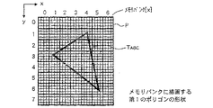
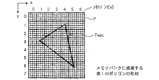
例えば、メモリバンク[X]上に描画するポリゴンの形状が図7に示すような三角形T
ABC (第1のポリゴンの形状)であった場合、先ず、プリプロセッサ32から制御回路1
01には、ピクセルインターリーブの制御情報が供給される。
For example, the shape of the polygon drawn on the memory bank [X] is a triangle T as shown in FIG.
In the case of ABC (the shape of the first polygon), first, the
01 is supplied with pixel interleaving control information.
制御回路101は、プリプロセッサ32からのピクセルインターリーブの制御情報に基
いて、三角形TABC 内部をアクセスする際に用いるインターリーブパターンを、例えば、
(4×4)のインターリーブパターンPに切り換える。
Based on the pixel interleaving control information from the
Switch to the (4 × 4) interleave pattern P.
なお、制御回路101におけるインターリーブパターンの切換方法についての詳細は後
述する。
The details of the interleave pattern switching method in the control circuit 101 will be described later.
そして、制御回路101は、(4×4)のインターリーブパターンPを用いて、メモリ
バンク[X]上に形成される複数のインターリーブパターンのうち、アクセスすべきイン
ターリーブパターン、すなわち三角形TABC 内部を全てアクセスすることができるような
インターリーブパターンを検出する。
The control circuit 101 uses the (4 × 4) interleave pattern P to access all of the interleave patterns to be accessed among the plurality of interleave patterns formed on the memory bank [X], that is, the inside of the triangle TABC. An interleave pattern that can be detected is detected.
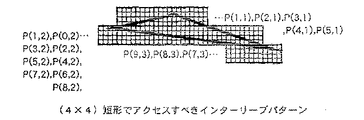
したがって、三角形TABC では、メモリバンク[X]上の各インターリーブパターンを
P(x方向のパターンインデックス,y方向のパターンインデックス)で示した場合、図
8に示すように、
P(x,y)=P(3,1),P(4,1),P(1,2),P(2,2),
P(3,2),P(4,2),P(1,3),P(2,3),
P(3,3),P(4,3),P(5,3),P(2,4),
P(3,4),P(4,4),P(5,4),P(3,5),
P(4,5),P(5,5),P(4,6),P(5,6)
で示される合計20個のインターリーブパターンが検出される。
Therefore, in the triangle TABC, when each interleave pattern on the memory bank [X] is indicated by P (pattern index in the x direction, pattern index in the y direction), as shown in FIG.
P (x, y) = P (3,1), P (4,1), P (1,2), P (2,2),
P (3,2), P (4,2), P (1,3), P (2,3),
P (3,3), P (4,3), P (5,3), P (2,4),
P (3,4), P (4,4), P (5,4), P (3,5),
P (4,5), P (5,5), P (4,6), P (5,6)
A total of 20 interleave patterns indicated by are detected.
そして、制御回路101は、上述のようにして検出した20個のインターリーブパター
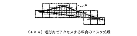
ンを示すパターン情報をインターリーブパターン単位でセレクタ102に供給する。また
、1アドレス単位でメモリアクセスを行う場合には、制御回路101は、三角形TABC の
形状に基いたマスク情報をセレクタ102に供給する。
Then, the control circuit 101 supplies pattern information indicating the 20 interleave patterns detected as described above to the selector 102 in units of interleave patterns. When performing memory access in units of one address, the control circuit 101 supplies mask information based on the shape of the triangle TABC to the selector 102.
セレクタ102は、制御回路101からインターリーブパターン単位で供給されたパタ
ーン情報に基いて、アクセスすべき(4×4)のインターリーブパターンPに対応したア
ドレスをMUX/DMUX103a,103b,103c,103dに指定する。
Based on the pattern information supplied in units of interleave patterns from the control circuit 101, the selector 102 designates the addresses corresponding to the (4 × 4) interleave pattern P to be accessed in the MUX /
また、セレクタ102は、制御回路101からマスク情報が供給された場合には、その
マスク情報に基いて、図9に示すように、(4×4)のインターリーブパターンPのなか
でマスクを行った結果得られるアクセスすべきアドレスをMUX/DMUX103a,1
03b,103c,103dに指定する。したがって、例えば、図10に示すように、上
記図9に示したP(4,1)で示されるインターリーブパターン内のアドレスA0 〜A15
において、マスクを行った結果得られるアクセスすべきアドレスは、A4,A5,A6,
A8,A9,A10,A13,A14,A15(斜線部分)となる。
Further, when the mask information is supplied from the control circuit 101, the selector 102 performs masking in the (4 × 4) interleave pattern P based on the mask information as shown in FIG. The resulting address to be accessed is MUX /
Specify 03b, 103c, 103d. Therefore, for example, as shown in FIG. 10, addresses A0 to A15 in the interleave pattern indicated by P (4,1) shown in FIG.
The addresses to be accessed obtained as a result of masking are A4, A5, A6,
A8, A9, A10, A13, A14, and A15 (shaded portions).
MUX/DMUX103a,103b,103c,103dは、各々、メモリバンク[
X]のアドレスA0 〜A15のうち、セレクタ102により指定されたアドレスをアクセス
する。
The MUX /
X] of the addresses A0 to A15, the address designated by the selector 102 is accessed.
ここで、上述したように、ピクセルエンジン33DX1,33DX2,33DX3,33DX4
からMUX/DMUX103a,103b,103c,103dには、各々、画素データ
が供給されるようになされている。
Here, as described above, the pixel engines 33DX1, 33DX2, 33DX3, 33DX4.
To MUX /
そこで、例えば、MUX/DMUX103aは、セレクタ102により指定されたアド
レスをアクセスすることにより、入出力ポートP0 〜P15のうち上記アドレスに対応した
入出力ポートを介して、ピクセルエンジンXaからの画素データをメモリバンク[X]の
上記アドレスにより示される領域に書き込む。
Therefore, for example, the MUX / DMUX 103a accesses the address designated by the selector 102, and receives the pixel data from the pixel engine Xa through the input / output port corresponding to the address among the input / output ports P0 to P15. Write to the area indicated by the address in the memory bank [X].
また、MUX/DMUX103aは、セレクタ102により指定されたアドレスをアク
セスすることにより、入出力ポートP0 〜P15のうち上記アドレスに対応した入出力ポー
トを介して、メモリバンク[X]の上記アドレスにより示される領域に書き込まれている
データを読み出す。そして、MUX/DMUX103aは、メモリバンク[X]から読み
出したデータに対して所定の処理を行う。
Further, the MUX / DMUX 103a accesses the address designated by the selector 102, thereby indicating the address of the memory bank [X] through the input / output port corresponding to the address among the input / output ports P0 to P15. Read the data written in the read area. Then, the MUX / DMUX 103a performs predetermined processing on the data read from the memory bank [X].
なお、MUX/DMUX103b〜103dの動作については、上述したMUX/DM
UX103aの動作と同様であるため、その詳細な説明は省略する。
In addition, about operation | movement of MUX / DMUX103b-103d, MUX / DM mentioned above is mentioned.
Since the operation is the same as that of the UX 103a, detailed description thereof is omitted.
つぎに、上述した制御回路101におけるインターリーブパターンの切換方法について
具体的に説明する。
Next, a method for switching the interleave pattern in the control circuit 101 described above will be specifically described.
まず、メモリバンク[X]上に描画するポリゴンの形状が、例えば、図11に示すよう
にな横長の三角形TDEF (第2のポリゴンの形状)であり、三角形TDEF を(4×4)の
インターリーブパターンPでアクセスする場合のアクセス回数について説明する。
First, the polygon shape drawn on the memory bank [X] is, for example, a horizontally long triangle TDEF (the shape of the second polygon) as shown in FIG. 11, and the triangle TDEF is interleaved with (4 × 4). The number of accesses when accessing with the pattern P will be described.
この場合、アクセスすべきインターリーブパターンの個数は、図12に示すように、
P(x,y)=P(1,1),P(2,1),P(3,1),
P(4,1),P(5,1),P(0,2),
P(1,2),P(2,2),P(3,2),
P(4,2),P(5,2),P(6,2),
P(7,2),P(8,2),P(7,3),
P(8,3),P(9,3)
の合計17個となる。
In this case, the number of interleave patterns to be accessed is as shown in FIG.
P (x, y) = P (1,1), P (2,1), P (3,1),
P (4,1), P (5,1), P (0,2),
P (1,2), P (2,2), P (3,2),
P (4,2), P (5,2), P (6,2),
P (7,2), P (8,2), P (7,3),
P (8,3), P (9,3)
The total is 17.
すなわち、(4×4)のインターリーブパターンPで三角形TDEF をアクセスする場合
、三角形TDEF 内部を全てアクセスするためのアクセス回数は、17回となる。
That is, when the triangle TDEF is accessed with the (4 × 4) interleave pattern P, the access count for accessing all the inside of the triangle TDEF is 17 times.
また、1アドレス単位でアクセスする場合には、上述した三角形TABC のアクセス時と
同様に、図13に示すように、(4×4)のインターリーブパターンPのなかでマスクを
行うことにより、必要なメモリアドレスのみをアクセスすることとなる。
Also, when accessing in units of one address, as in the case of accessing the triangle TABC described above, as shown in FIG. 13, by masking within the (4 × 4) interleave pattern P, it is necessary to Only the memory address is accessed.
つぎに、図14に示すように、三角形TDEF を(8×2)のインターリーブパターンP
1 でアクセスする場合、アクセスすべきインターリーブパターンの個数は、図15に示す
ように、
P1(x,y)=P1(1,2),P1(2,2),P1(0,3),
P1(1,3),P1(2,3),P1(0,4),
P1(1,4),P1(2,4),P1(3,4),
P1(1,5),P1(2,5),P1(3,5),
P1(4,5),P1(3,6),P1(4,6)
の合計15個となる。
Next, as shown in FIG. 14, the triangle TDEF is changed to an (8 × 2) interleave pattern P.
When accessing with 1, the number of interleave patterns to be accessed is as shown in FIG.
P1 (x, y) = P1 (1,2), P1 (2,2), P1 (0,3),
P1 (1,3), P1 (2,3), P1 (0,4),
P1 (1,4), P1 (2,4), P1 (3,4),
P1 (1,5), P1 (2,5), P1 (3,5),
P1 (4,5), P1 (3,6), P1 (4,6)
The total is 15.
すなわち、(8×2)のインターリーブパターンP1 で三角形TDEF をアクセスする場
合、三角形TDEF 内部を全てアクセスするためのアクセス回数は、15回となる。
That is, when the triangle TDEF is accessed with the (8 × 2) interleave pattern P1, the number of accesses for accessing the entire inside of the triangle TDEF is 15.
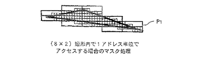
また、1アドレス単位でアクセスする場合には、上述した三角形TABC のアクセス時と
同様に、図16に示すように、(8×2)のインターリーブパターンP1 のなかでマスク
を行うことにより、必要なメモリアドレスのみをアクセスすることとなる。
Further, when accessing in units of one address, as in the case of accessing the triangle TABC described above, as shown in FIG. Only the memory address is accessed.
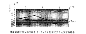
つぎに、図17に示すように、三角形TDEF を(16×1)のインターリーブパターン
P2 でアクセスする場合、アクセスすべきインターリーブパターンの個数は、図18に示
すように、
P2(x,y)=P2(0,5),P2(1,5),P2(0,6),
P2(1,6),P2(0,7),P2(1,7),
P2(0,8),P2(1,8),P2(0,9),
P2(1,9),P2(0,10),P2(1,10),
P2(2,10),P2(1,11),P2(2,11),
P2(1,12),P2(2,12),P2(2,13)
の合計18個となる。
Next, as shown in FIG. 17, when the triangle TDEF is accessed with the (16 × 1) interleave pattern P2, the number of interleave patterns to be accessed is as shown in FIG.
P2 (x, y) = P2 (0,5), P2 (1,5), P2 (0,6),
P2 (1,6), P2 (0,7), P2 (1,7),
P2 (0,8), P2 (1,8), P2 (0,9),
P2 (1,9), P2 (0,10), P2 (1,10),
P2 (2, 10), P2 (1, 11), P2 (2, 11),
P2 (1,12), P2 (2,12), P2 (2,13)
18 in total.
すなわち、(16×1)のインターリーブパターンP2 で三角形TDEF をアクセスする
場合、三角形TDEF 内部を全てアクセスするためのアクセス回数は、18回となる。
That is, when the triangle TDEF is accessed with the (16 × 1) interleave pattern P2, the number of accesses for accessing all the inside of the triangle TDEF is 18.
また、1アドレス単位でアクセスする場合には、上述した三角形TABC のアクセス時と
同様に、図19に示すように、(8×2)のインターリーブパターンP2 のなかでマスク
を行うことにより、必要なメモリアドレスのみをアクセスすることとなる。
Also, when accessing in units of one address, as in the case of accessing the triangle TABC described above, as shown in FIG. 19, by masking in the (8 × 2) interleave pattern P2, it is necessary to Only the memory address is accessed.
上述のように、(4×4)のインターリーブパターンPで三角形TDEF をアクセスする
場合のアクセス回数は17回、(8×2)のインターリーブパターンP1で三角形TDEF
をアクセスする場合のアクセス回数は15回、(16×1)のインターリーブパターンP
2 で三角形TDEF をアクセスする場合のアクセス回数は18回となり、この結果、(8×
2)のインターリーブパターンP1 で三角形TDEF をアクセスする場合のアクセス回数が
最少のアクセス回数となる。したがって、三角形TDEF に対する適切なインターリーブパ
ターンは、(8×2)のインターリーブパターンP1ということがわかる。
As described above, when the triangle TDEF is accessed with the (4 × 4) interleave pattern P, the access count is 17 times, and the triangle TDEF is accessed with the (8 × 2) interleave pattern P1.
Is accessed 15 times, and the (16 × 1) interleave pattern P
When the triangle TDEF is accessed with 2, the number of accesses is 18 times. As a result, (8 ×
In the case of accessing the triangle TDEF with the interleave pattern P1 of 2), the access count becomes the minimum access count. Therefore, it can be seen that an appropriate interleave pattern for the triangle TDEF is an (8 × 2) interleave pattern P1.
そこで、制御回路101は、メモリバンク[X]をアクセスする際に用いるインターリ
ーブパターンを、アクセスするポリゴンの形状に応じた適切なインターリーブパターンに
切り換えるために、以下のような処理を行う。
Therefore, the control circuit 101 performs the following processing to switch the interleave pattern used when accessing the memory bank [X] to an appropriate interleave pattern according to the shape of the polygon to be accessed.
例えば、メモリバンク[X]上に描画するポリゴンの形状が図20に示すような三角形
THIJ であった場合、先ず、制御回路101には、上述したように、プリプロセッサ32
からピクセルインターリーブの制御情報が供給される。このピクセルインターリーブの制
御情報は、例えば、三角形THIJの3つの頂点H,I,Jのxy座標H(Xh,Yh),
I(Xi,Yi),J(Xj,Yj)等の情報である。
For example, when the shape of the polygon drawn on the memory bank [X] is a triangle THIJ as shown in FIG. 20, first, as described above, the control circuit 101 includes the
To provide pixel interleave control information. The pixel interleaving control information is, for example, the xy coordinates H (Xh, Yh) of the three vertices H, I, and J of the triangle THIJ.
Information such as I (Xi, Yi), J (Xj, Yj).
次に、制御回路101は、上記図20に示すように、プリプロセッサ32からのピクセ
ルインターリーブの制御情報を用いて、三角形THIJ の縦横比Rを、X方向の最大値MA
Xx及び最少値MINx、Y方向の最大値MAXy及び最少値MINyを持って、
R=dy/dx
=(MAXx−MINx)/(MAXy−MINy)
なる演算により求める。
Next, as shown in FIG. 20, the control circuit 101 uses the pixel interleaving control information from the
Xx and minimum value MINx, maximum value MAXy in Y direction and minimum value MINy,
R = dy / dx
= (MAXx-MINx) / (MAXy-MINy)
Is obtained by the following calculation.
なお、三角形THIJ では、
MAXx=Xj
MINx=Xi
MAXy=Yh
MINy=Yi
となる。
In triangle THIJ,
MAXx = Xj
MINx = Xi
MAXy = Yh
MINy = Yi
It becomes.
そして、制御回路101は、上述のようにして求めた縦横比Rに応じて、図21に示す
ような、(1×16)、(2×8)、(4×4)、(8×2)、(16×1)の5種類の
インターリーブパターンPa〜Peのうち適切なインターリーブパターンを選出し、三角
形THIJ をアクセスする際に用いるインターリーブパターンを、選出したインターリーブ
パターンに切り換える。
Then, according to the aspect ratio R obtained as described above, the control circuit 101 (1 × 16), (2 × 8), (4 × 4), (8 × 2) as shown in FIG. ) And (16 × 1) of the five types of interleave patterns Pa to Pe, an appropriate interleave pattern is selected, and the interleave pattern used when accessing the triangle THIJ is switched to the selected interleave pattern.
ここで、制御回路101は、表1に示すような、縦横比Rとインターリーブパターンと
対応表からなるテーブルを有している。このテーブルには、縦横比Rに応じた適切なイン
ターリーブパターン、すなわちアクセス回数が最小となるようなインターリーブパターン
が予め設定されている。したがって、制御回路101は、上記テーブルを用いることによ
り、上述のようにして得られた縦横比Rに基いた適切なインターリーブパターンを選出す
ることとなる。
Here, the control circuit 101 has a table including an aspect ratio R, an interleave pattern, and a correspondence table as shown in Table 1. In this table, an appropriate interleave pattern corresponding to the aspect ratio R, that is, an interleave pattern that minimizes the number of accesses is set in advance. Therefore, the control circuit 101 selects an appropriate interleave pattern based on the aspect ratio R obtained as described above by using the table.
上述のように、第2のバススイッチャ33Eでは、メモリバンク[X]上に描画するポ
リゴンの形状に応じて、上記図21に示したような5種類のインターリーブパターンPa
〜Peから適切なインターリーブパターンを選出し、選出したインターリーブパターンで
メモリバンク[X]をアクセスするため、最小のアクセス回数でメモリバンク[X]上に
上記ポリゴンを描画することができる。したがって、第2のバススイッチャ33Eは、メ
モリアクセスを効率良く行うことができる。
As described above, in the
Since an appropriate interleave pattern is selected from ~ Pe and the memory bank [X] is accessed using the selected interleave pattern, the polygon can be drawn on the memory bank [X] with the minimum number of accesses. Therefore, the
また、GPU15は、上述のような、メモリアクセスの効率化を図った第2のバススイ
ッチャ33Eにより、フレームバッファ18をアクセスしてデータ処理を行うため、その
データ処理を効率良く行うことができる。
Further, since the
1 メインバス、11 メインCPU、12 メインメモリ、13 メインDMAC、 1
5 GPU、17 GTE、18 フレームバッファ、31 パケットエンジン、32 プリ
プロセッサ、33 描画エンジン、33A1,33A2・・・33AN ポリゴンエンジン
、33B1,33B2・・・33BN テクスチャエンジン、33C 第1のバススイッチ
ャ、33D1,33D2・・・33DM、33E 第2のバススイッチャ、33F テクス
チャキャッシュ
1 main bus, 11 main CPU, 12 main memory, 13 main DMAC, 1
5 GPU, 17 GTE, 18 frame buffer, 31 packet engine, 32 preprocessor, 33 rendering engine, 33A1, 33A2 ... 33AN polygon engine, 33B1,33B2, ... 33BN texture engine, 33C first bus switcher, 33D1, 33D2 ... 33DM, 33E Second bus switcher, 33F Texture cache
Claims (2)
上記画像メモリには、テクスチャデータが格納されていて、
上記描画命令に基づいて、
単位図形を3次元空間で複数に分割する手段と、
上記分割手段により分割された各単位図形に貼り付ける必要なテクスチャのアドレスを、該単位図形毎に順次、生成する前処理手段と、
上記前処理手段が生成した上記テクスチャのアドレスに基づいて、上記画像メモリから、該テクスチャのアドレスに対応するテクスチャデータを読み出す手段と、を有し、
上記描画手段は、上記読み出したテクスチャデータを用いて上記単位図形毎にテクスチャマッピングを行い、
上記分割する手段は、
単位図形の頂点の奥行きを示すZ値の最小値と最大値との差が所定の範囲内に収まっているか否かにより、上記単位図形の分割を行うか否かを判定する判定手段を備え、
上記分割を行なう判定をした場合、上記描画命令に基づく単位図形を3次元空間で複数に分割し、
上記読み出す手段は、上記テクスチャデータの読み出しを、上記描画手段が行なう単位図形毎のテクスチャマッピングに先立って完了するように行なうこと
を特徴とする描画装置。 A drawing device that generates pixel data of all pixels of a unit graphic by a drawing unit based on a drawing command for drawing an image model defined by a combination of unit graphics, and draws the image data in an image memory,
The image memory stores texture data,
Based on the above drawing command,
Means for dividing the unit figure into a plurality of three-dimensional spaces;
Pre-processing means for sequentially generating, for each unit graphic, an address of a texture necessary to be pasted on each unit graphic divided by the dividing means ;
Means for reading texture data corresponding to the texture address from the image memory based on the texture address generated by the preprocessing means;
The drawing means performs texture mapping for each unit graphic using the read texture data,
The means for dividing is as follows:
Determining means for determining whether to divide the unit graphic depending on whether the difference between the minimum value and the maximum value of the Z value indicating the depth of the vertex of the unit graphic is within a predetermined range;
When it is determined to perform the division, the unit graphic based on the drawing command is divided into a plurality of pieces in a three-dimensional space,
The drawing device, wherein the reading means performs reading of the texture data prior to texture mapping for each unit graphic performed by the drawing means.
上記描画命令に基づいて、
単位図形を3次元空間で複数に分割するステップと、
上記分割するステップにより分割された各単位図形に貼り付ける必要なテクスチャのアドレスを、該単位図形毎に順次、生成するステップと、
上記生成した上記テクスチャのアドレスに基づいて、上記画像メモリに予め格納されているテクスチャデータの中から対応するテクスチャデータを読み出すステップと、
上記読み出したテクスチャデータを用いて上記単位図形毎にテクスチャマッピングを行なうステップと、を有し、
上記分割するステップは、単位図形の頂点の奥行きを示すZ値の最小値と最大値との差が所定の範囲内に収まっているか否かにより、上記単位図形の分割を行うか否かを判定し、
上記分割を行なう判定をした場合、上記描画命令に基づく単位図形を3次元空間で複数に分割し、
上記読み出すステップは、上記テクスチャデータの読み出しを、上記テクスチャマッピングを行なうステップに先立って完了するように行なうこと
を特徴とする描画方法。 A drawing method for generating pixel data of all pixels of a unit graphic based on a drawing command for drawing an image model defined by a combination of unit graphics, and drawing the image data in an image memory,
Based on the above drawing command,
Dividing the unit figure into a plurality of three-dimensional spaces;
A step of sequentially generating, for each unit graphic, an address of a texture necessary to be pasted on each unit graphic divided by the dividing step;
Reading the corresponding texture data from the texture data stored in advance in the image memory based on the generated texture address;
Performing texture mapping for each unit graphic using the read texture data,
The step of dividing determines whether or not to divide the unit graphic depending on whether or not the difference between the minimum value and the maximum value of the Z value indicating the depth of the vertex of the unit graphic is within a predetermined range. And
When it is determined to perform the division, the unit graphic based on the drawing command is divided into a plurality of pieces in a three-dimensional space,
The drawing method, wherein the reading step is performed so that reading of the texture data is completed prior to the step of performing the texture mapping.
Priority Applications (1)
| Application Number | Priority Date | Filing Date | Title |
|---|---|---|---|
| JP2006301059A JP3971448B2 (en) | 2006-11-07 | 2006-11-07 | Drawing apparatus and drawing method |
Applications Claiming Priority (1)
| Application Number | Priority Date | Filing Date | Title |
|---|---|---|---|
| JP2006301059A JP3971448B2 (en) | 2006-11-07 | 2006-11-07 | Drawing apparatus and drawing method |
Related Parent Applications (1)
| Application Number | Title | Priority Date | Filing Date |
|---|---|---|---|
| JP2004027663A Division JP3934111B2 (en) | 2004-02-04 | 2004-02-04 | Drawing apparatus and drawing method |
Publications (2)
| Publication Number | Publication Date |
|---|---|
| JP2007026473A JP2007026473A (en) | 2007-02-01 |
| JP3971448B2 true JP3971448B2 (en) | 2007-09-05 |
Family
ID=37787073
Family Applications (1)
| Application Number | Title | Priority Date | Filing Date |
|---|---|---|---|
| JP2006301059A Expired - Fee Related JP3971448B2 (en) | 2006-11-07 | 2006-11-07 | Drawing apparatus and drawing method |
Country Status (1)
| Country | Link |
|---|---|
| JP (1) | JP3971448B2 (en) |
Families Citing this family (1)
| Publication number | Priority date | Publication date | Assignee | Title |
|---|---|---|---|---|
| KR100901273B1 (en) | 2007-12-15 | 2009-06-09 | 한국전자통신연구원 | Rendering system and data processing method using by it |
-
2006
- 2006-11-07 JP JP2006301059A patent/JP3971448B2/en not_active Expired - Fee Related
Also Published As
| Publication number | Publication date |
|---|---|
| JP2007026473A (en) | 2007-02-01 |
Similar Documents
| Publication | Publication Date | Title |
|---|---|---|
| JP3645024B2 (en) | Drawing apparatus and drawing method | |
| TW200933523A (en) | Graphics processing units and execution units | |
| JPH09212661A (en) | Picture generator | |
| US7170512B2 (en) | Index processor | |
| WO2006028093A1 (en) | Video generation device and video generation method | |
| JPH09212146A (en) | Address generation device and picture display device | |
| JP2882465B2 (en) | Image generation method and apparatus | |
| EP1312047B1 (en) | Apparatus and method for rendering antialiased image | |
| KR100471905B1 (en) | Memory access method and data processing device | |
| US6992673B2 (en) | Memory access device, semiconductor device, memory access method, computer program and recording medium | |
| US6466219B1 (en) | Storage device and image data processing apparatus | |
| JP2005332195A (en) | Texture unit, image drawing apparatus, and texel transfer method | |
| JP3971448B2 (en) | Drawing apparatus and drawing method | |
| JP3548648B2 (en) | Drawing apparatus and drawing method | |
| US7372461B2 (en) | Image processing apparatus and method of same | |
| JP3934111B2 (en) | Drawing apparatus and drawing method | |
| JP3910259B2 (en) | Image processing apparatus and method, and rendering apparatus and method | |
| JP3468985B2 (en) | Graphic drawing apparatus and graphic drawing method | |
| JP2003263650A (en) | Image processor and image processing method | |
| JPH11316856A (en) | Picture processor | |
| JP2003296748A (en) | Image processor and method thereof | |
| JP4482996B2 (en) | Data storage apparatus and method and image processing apparatus | |
| JP4271270B2 (en) | DATA STORAGE DEVICE, DATA STORAGE DEVICE CONTROL DEVICE AND METHOD, AND IMAGE GENERATION DEVICE | |
| JP4194605B2 (en) | Image processing apparatus and method, and rendering apparatus and method | |
| JP2003022696A (en) | Test circuit and image processor |
Legal Events
| Date | Code | Title | Description |
|---|---|---|---|
| A521 | Written amendment |
Free format text: JAPANESE INTERMEDIATE CODE: A523 Effective date: 20061107 |
|
| A621 | Written request for application examination |
Free format text: JAPANESE INTERMEDIATE CODE: A621 Effective date: 20061107 |
|
| A131 | Notification of reasons for refusal |
Free format text: JAPANESE INTERMEDIATE CODE: A131 Effective date: 20070220 |
|
| A521 | Written amendment |
Free format text: JAPANESE INTERMEDIATE CODE: A523 Effective date: 20070412 |
|
| TRDD | Decision of grant or rejection written | ||
| A01 | Written decision to grant a patent or to grant a registration (utility model) |
Free format text: JAPANESE INTERMEDIATE CODE: A01 Effective date: 20070515 |
|
| A61 | First payment of annual fees (during grant procedure) |
Free format text: JAPANESE INTERMEDIATE CODE: A61 Effective date: 20070607 |
|
| R150 | Certificate of patent or registration of utility model |
Free format text: JAPANESE INTERMEDIATE CODE: R150 |
|
| FPAY | Renewal fee payment (event date is renewal date of database) |
Free format text: PAYMENT UNTIL: 20100615 Year of fee payment: 3 |
|
| FPAY | Renewal fee payment (event date is renewal date of database) |
Free format text: PAYMENT UNTIL: 20110615 Year of fee payment: 4 |
|
| FPAY | Renewal fee payment (event date is renewal date of database) |
Free format text: PAYMENT UNTIL: 20110615 Year of fee payment: 4 |
|
| FPAY | Renewal fee payment (event date is renewal date of database) |
Free format text: PAYMENT UNTIL: 20120615 Year of fee payment: 5 |
|
| FPAY | Renewal fee payment (event date is renewal date of database) |
Free format text: PAYMENT UNTIL: 20120615 Year of fee payment: 5 |
|
| FPAY | Renewal fee payment (event date is renewal date of database) |
Free format text: PAYMENT UNTIL: 20130615 Year of fee payment: 6 |
|
| R250 | Receipt of annual fees |
Free format text: JAPANESE INTERMEDIATE CODE: R250 |
|
| R250 | Receipt of annual fees |
Free format text: JAPANESE INTERMEDIATE CODE: R250 |
|
| LAPS | Cancellation because of no payment of annual fees |