JP3971237B2 - Engine mount bracket - Google Patents
Engine mount bracket Download PDFInfo
- Publication number
- JP3971237B2 JP3971237B2 JP2002135920A JP2002135920A JP3971237B2 JP 3971237 B2 JP3971237 B2 JP 3971237B2 JP 2002135920 A JP2002135920 A JP 2002135920A JP 2002135920 A JP2002135920 A JP 2002135920A JP 3971237 B2 JP3971237 B2 JP 3971237B2
- Authority
- JP
- Japan
- Prior art keywords
- engine mount
- base plate
- plate
- divided
- side rail
- Prior art date
- Legal status (The legal status is an assumption and is not a legal conclusion. Google has not performed a legal analysis and makes no representation as to the accuracy of the status listed.)
- Expired - Fee Related
Links
Images
Landscapes
- Arrangement Or Mounting Of Propulsion Units For Vehicles (AREA)
Description
【0001】
【発明の属する技術分野】
本発明は、エンジンマウントブラケットに関するものである。
【0002】
【従来の技術】
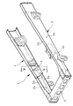
図4は従来の大型トラックにおけるフレーム構造の前方部分を示すもので、ここに図示されている通り、シャシフレーム1は、左右のサイドレール2,2の長手方向複数箇所をクロスメンバ3(図4にはフロントクロスメンバのみが図示されている)により車幅方向に連結されて構成されており、一般的に、前記両サイドレール2,2は、車幅方向内側に向け溝形を成すチャンネル材により構成されている。
【0003】
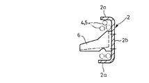
そして、図5に示す如く、サイドレール2,2の上下のフランジ2aとウェブ2bとにより囲まれた空間には、シャシフレーム1の後方に搭載される各種の機器類からのハーネス4や配管5が配索されて、キャブが搭載されるシャシフレーム1の前方側へ導かれるようになっている。
【0004】
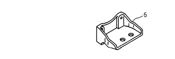
ただし、左右のサイドレール2,2の前方寄りの部分には、図示しないエンジンマウントを受けてエンジン荷重を支えるためのエンジンマウントブラケット6(図6参照)が両サイドレール2,2のウェブ2bの内側面に基端部を締結して装備されるようになっているので、このエンジンマウントブラケット6を避けてハーネス4や配管5を配索する必要がある。
【0005】
【発明が解決しようとする課題】
しかしながら、近年においては、キャブ内に電子機器類等が増えてきたこと等を要因として、両サイドレール2,2に沿わせて配索しなければならないハーネス4や配管5の本数が増えてきており、また、その太さも大きくなる傾向にあるので、サイドレール2,2の内側におけるエンジンマウントブラケット6の占有スペースを除いた余剰空間だけでは、ハーネス4や配管5を配索するに足る十分な空間を確保することが困難になってきている。
【0006】
本発明は上述の実情に鑑みてなしたもので、ハーネスや配管を配索するための配索空間を従来より大きく確保し得るエンジンマウントブラケットを提供することを目的とする。
【0007】
【課題を解決するための手段】
本発明は、車幅方向内側に向け溝形を成すサイドレールの前方部分に装備されるエンジンマウントブラケットであって、サイドレールの車幅方向内側に溝形の開口部を塞ぐように装着されて該サイドレールと共に閉断面の配索空間を画成するベースプレートと、該ベースプレートの車幅方向内側面に装着されてエンジンマウントを受けるブラケット本体とを備え、しかも、ベースプレートが上下に分割され、その分割された何れか一方の分割プレートによりブラケット本体が支持されるように構成されており、更には、上側の分割プレートの上端部がサイドレールの上側のフランジ下面に重ねて締結され且つその下端部が下方向きに屈曲して下側の分割プレートとの連結部を成すように形成されていると共に、下側の分割プレートの上端部が前記上側の分割プレートの下端部と連結されて下方向きに延び且つその下端部が車幅方向外側に屈曲してサイドレールの下側のフランジの上面に重ねて締結されるように形成されていることを特徴とするものである。
【0008】
而して、このようにすれば、エンジンマウントを受けるブラケット本体が、サイドレールとベースプレートとにより画成された配索空間の外に配置されることになるので、このブラケット本体の占有スペースを考慮せずに配索空間の全てをハーネスや配管の配索に使用することが可能となる。
【0009】
また、本発明においては、ベースプレートが上下に分割され、その分割された何れか一方の分割プレートによりブラケット本体が支持されるように構成されているので、上下の分割プレートの連結位置を適宜に調整することでベースプレートの高さ寸法を調整することが可能となり、サイドレール側に対し高い精度でベースプレートを製作しなくてもエンジンマウントブラケットを装着することが可能となる。
【0012】
【発明の実施の形態】
以下本発明の実施の形態を図面を参照しつつ説明する。
【0013】
図1〜図3は本発明を実施する形態の一例を示すもので、図4及び図5と同一の符号を付した部分は同一物を表わしている。
【0014】
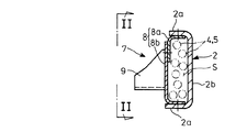
本形態例においては、車幅方向内側に向け溝形を成すサイドレール2,2(図1〜図3には片側のサイドレールについてだけ図示している)の前方部分に装備されるエンジンマウントブラケット7を、以下に詳述する如きベースプレート8とブラケット本体9とにより構成するようにしている。
【0015】
即ち、ここに図示しているエンジンマウントブラケット7は、サイドレール2の車幅方向内側に溝形の開口部を塞ぐように装着されて該サイドレール2と共に閉断面の配索空間Sを画成するベースプレート8と、該ベースプレート8の車幅方向内側面に装着されて図示しないエンジンマウントを受けるブラケット本体9とを備えて構成されており、しかも、前記ベースプレート8が、比較的高い位置で上側の分割プレート8aと下側の分割プレート8bとに二分割されている。
【0016】
そして、上側の分割プレート8aの上端部をサイドレール2の上部のフランジ2a下面に重ねて締結し且つその下端部を下方向きに屈曲させて下側の分割プレート8bとの連結部を成すように形成しており、下側の分割プレート8bの上端部を前記上側の分割プレート8aの下端部と連結して下方向きに延ばし且つその下端部を車幅方向外側に屈曲させてサイドレール2の下部のフランジ2aの上面に重ねて締結させるようにしている。
【0017】
而して、このようにすれば、エンジンマウントを受けるブラケット本体9が、サイドレール2とベースプレート8とにより画成された配索空間Sの外に配置されることになるので、このブラケット本体9の占有スペースを考慮せずに配索空間Sの全てをハーネス4や配管5の配索に使用することが可能となる。
【0018】
しかも、本形態例においては、ベースプレート8を上側の分割プレート8aと下側の分割プレート8bとに二分割し、その下側の分割プレート8bによりブラケット本体9が装着されるようにしているので、これらの上下の分割プレート8a,8bを締結する際に、例えば、その締結孔を上下方向に延びる長孔等としておけば、上側の分割プレート8aの下端部と下側の分割プレート8bの上端部との上下の重なり量を適宜に調整して相互の締結を図ることが可能となり、サイドレール2側に対し高い精度でベースプレート8を製作しなくてもエンジンマウントブラケット7を容易に装着することが可能となる。
【0019】
即ち、配索空間Sをできるだけ広く確保しようとすれば、自ずから図1の如きサイドレール2の溝形に対峙するような溝形を成すベースプレート8を前記サイドレール2の上下のフランジ2aに対し締結して装着することになるが、このようにした場合に、ベースプレート8を一体成型品として製作してしまうと、サイドレール2の上下のフランジ2a相互間の間隔とベースプレート8の高さ寸法が高い精度で等しくならない限り良好な装着が実現されなくなって、エンジンマウントブラケット7の製作コストの高騰や組付け作業性の低下を招くことが懸念されるので、ベースプレート8を上下に分割して高さ寸法を調整し得るようにしているのである。
【0020】
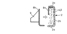
尚、配索空間Sにハーネス4や配管5を配索するにあたっては、閉断面の配索空間Sを完成させた後から多数のハーネス4や配管5をカプラと共に配索空間Sに通すことが困難であるので、図3に示す如く、少なくとも分割プレート8bを装着する前に、未だ完全に塞がれていないサイドレール2の溝形の開口部の隙間からハーネス4や配管5を収容させるようにすると良い。
【0021】
従って、上記形態例によれば、ブラケット本体9の占有スペースを考慮せずに配索空間Sの全てをハーネス4や配管5の配索に使用することができるので、ハーネス4や配管5を配索するための配索空間Sを従来より大きく確保することができ、しかも、ベースプレート8を上下に分割して高さ寸法を調整し得るようにしているので、サイドレール2側に対し高い精度でベースプレート8を製作しなくてもエンジンマウントブラケット7を容易に装着することができ、該エンジンマウントブラケット7の製作コストの高騰や組付け作業性の低下を回避することもできる。
【0022】
尚、本発明のエンジンマウントブラケットは、上述の形態例にのみ限定されるものではなく、図示例よりもベースプレートの上下分割位置を下げて上側の分割プレートにブラケット本体を装着させることも可能であること、その他、本発明の要旨を逸脱しない範囲内において種々変更を加え得ることは勿論である。
【0023】
【発明の効果】
上記した本発明のエンジンマウントブラケットによれば、下記の如き種々の優れた効果を奏し得る。
【0024】
(I)本発明の請求項1に記載の発明によれば、ブラケット本体の占有スペースを考慮せずに配索空間の全てをハーネスや配管の配索に使用することができて、ハーネスや配管を配索するための配索空間を従来より大きく確保することがことができる。
【0025】
(II)本発明の請求項1に記載の発明によれば、ベースプレートを上下に分割して高さ寸法を調整し得るようにしているので、サイドレール側に対し高い精度でベースプレートを製作しなくてもエンジンマウントブラケットを容易に装着することができ、該エンジンマウントブラケットの製作コストの高騰や組付け作業性の低下を回避することができる。
【図面の簡単な説明】
【図1】本発明を実施する形態の一例を示す断面図である。
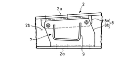
【図2】図1のII−II方向の矢視図である。
【図3】図1の上側の分割プレートを先行して装着した状態を示す断面図である。
【図4】従来例を示す斜視図である。
【図5】図4のV−V矢視の断面図である。
【図6】図4のエンジンマウントブラケットの拡大図である。
【符号の説明】
2 サイドレール
2a フランジ
4 ハーネス
5 配管
7 エンジンマウントブラケット
8 ベースプレート
8a 分割プレート
8b 分割プレート
9 ブラケット本体
S 配索空間[0001]
BACKGROUND OF THE INVENTION
The present invention relates to an engine mount bracket.
[0002]
[Prior art]
FIG. 4 shows a front portion of a frame structure in a conventional large truck. As shown in FIG. 4, the
[0003]
As shown in FIG. 5, in a space surrounded by the upper and
[0004]
However, an engine mount bracket 6 (see FIG. 6) for receiving an engine mount (not shown) and supporting an engine load is provided on the front side of the left and
[0005]
[Problems to be solved by the invention]
However, in recent years, the number of harnesses 4 and pipes 5 that have to be routed along both
[0006]
The present invention has been made in view of the above circumstances, and an object of the present invention is to provide an engine mount bracket that can secure a wiring space for wiring a harness or a pipe larger than the conventional one.
[0007]
[Means for Solving the Problems]
The present invention is an engine mount bracket that is mounted on a front portion of a side rail that forms a groove shape toward the inner side in the vehicle width direction, and is mounted to close the groove-shaped opening on the inner side in the vehicle width direction of the side rail. A base plate that defines a closed cross-section routing space together with the side rails, and a bracket body that is mounted on an inner side in the vehicle width direction of the base plate and receives an engine mount , and the base plate is divided into upper and lower parts. The bracket main body is configured to be supported by any one of the divided plates, and the upper end of the upper divided plate is fastened to overlap the lower surface of the upper flange of the side rail, and the lower end is It is formed to bend downward and form a connecting portion with the lower divided plate, and the upper end of the lower divided plate is Serial is connected to the lower end of the upper division plate is formed so and its lower end extends downward direction is fastened to overlap the upper surface of the lower flange of the side rail is bent outward in the vehicle width direction It is characterized by this.
[0008]
Thus, in this way, the bracket body that receives the engine mount is disposed outside the routing space defined by the side rails and the base plate, so the space occupied by the bracket body is taken into consideration. It is possible to use the entire wiring space for wiring of harnesses and pipes without doing so.
[0009]
In the present invention, the base plate is divided into upper and lower parts, and the bracket main body is supported by one of the divided parts. Therefore, the connecting position of the upper and lower divided plates is adjusted appropriately. Thus, the height dimension of the base plate can be adjusted, and the engine mount bracket can be mounted without manufacturing the base plate with high accuracy on the side rail side.
[0012]
DETAILED DESCRIPTION OF THE INVENTION
Embodiments of the present invention will be described below with reference to the drawings.
[0013]
1 to 3 show an example of an embodiment for carrying out the present invention, and the same reference numerals as those in FIGS. 4 and 5 denote the same components.
[0014]
In this embodiment, an engine mount bracket mounted on the front portion of
[0015]
That is, the
[0016]
Then, the upper end of the upper divided
[0017]
Thus, the bracket
[0018]
Moreover, in this embodiment, the
[0019]
That is, in order to secure the wiring space S as wide as possible, the
[0020]
In wiring the harness 4 and the pipe 5 in the wiring space S, it is possible to pass a large number of the harness 4 and the pipe 5 through the wiring space S together with the coupler after the wiring space S having a closed section is completed. Since it is difficult, as shown in FIG. 3, at least before mounting the divided
[0021]
Therefore, according to the above embodiment, the entire wiring space S can be used for the wiring of the harness 4 and the piping 5 without considering the occupied space of the
[0022]
The engine mount bracket according to the present invention is not limited to the above-described embodiment, and the bracket body can be attached to the upper divided plate by lowering the vertical division position of the base plate as compared to the illustrated example. Of course, various changes can be made without departing from the scope of the present invention.
[0023]
【The invention's effect】
According to the engine mount bracket of the present invention described above, various excellent effects as described below can be obtained.
[0024]
(I) According to the invention described in
[0025]
(II) According to the invention described in
[Brief description of the drawings]
FIG. 1 is a cross-sectional view showing an example of an embodiment of the present invention.
FIG. 2 is a view taken in the direction of arrows II-II in FIG.
3 is a cross-sectional view showing a state in which the upper divided plate of FIG. 1 is mounted in advance. FIG.
FIG. 4 is a perspective view showing a conventional example.
5 is a cross-sectional view taken along arrows VV in FIG. 4;
6 is an enlarged view of the engine mount bracket of FIG. 4. FIG.
[Explanation of symbols]
2
Claims (1)
Priority Applications (1)
| Application Number | Priority Date | Filing Date | Title |
|---|---|---|---|
| JP2002135920A JP3971237B2 (en) | 2002-05-10 | 2002-05-10 | Engine mount bracket |
Applications Claiming Priority (1)
| Application Number | Priority Date | Filing Date | Title |
|---|---|---|---|
| JP2002135920A JP3971237B2 (en) | 2002-05-10 | 2002-05-10 | Engine mount bracket |
Publications (2)
| Publication Number | Publication Date |
|---|---|
| JP2003326982A JP2003326982A (en) | 2003-11-19 |
| JP3971237B2 true JP3971237B2 (en) | 2007-09-05 |
Family
ID=29698118
Family Applications (1)
| Application Number | Title | Priority Date | Filing Date |
|---|---|---|---|
| JP2002135920A Expired - Fee Related JP3971237B2 (en) | 2002-05-10 | 2002-05-10 | Engine mount bracket |
Country Status (1)
| Country | Link |
|---|---|
| JP (1) | JP3971237B2 (en) |
Families Citing this family (2)
| Publication number | Priority date | Publication date | Assignee | Title |
|---|---|---|---|---|
| JP4808008B2 (en) * | 2005-11-10 | 2011-11-02 | 日野自動車株式会社 | Vehicle engine mounting structure |
| CN116198304A (en) * | 2023-03-30 | 2023-06-02 | 哈尔滨东安汽车动力股份有限公司 | Multifunctional support structure |
-
2002
- 2002-05-10 JP JP2002135920A patent/JP3971237B2/en not_active Expired - Fee Related
Also Published As
| Publication number | Publication date |
|---|---|
| JP2003326982A (en) | 2003-11-19 |
Similar Documents
| Publication | Publication Date | Title |
|---|---|---|
| JP5492167B2 (en) | Bumper structure for vehicles | |
| JP5853811B2 (en) | Wire harness wiring device for slide sheet | |
| CN101077689B (en) | Conduit installation structure in sliding-out sunroof device | |
| JP3971237B2 (en) | Engine mount bracket | |
| CN105793117B (en) | Structure of the underrun protection | |
| JPH092323A (en) | Cross-member structure | |
| JP4591434B2 (en) | Wire harness routing direction regulating material | |
| JP6870059B2 (en) | Slide rail assembly | |
| KR100872671B1 (en) | Body guide bracket assembly for cowl cross bar side mounting | |
| JP5351643B2 (en) | Slide sheet feeding structure | |
| JP2026028328A (en) | Bracket for wiring inside the frame | |
| JP4206806B2 (en) | Rear body structure of car with frame | |
| CN216215675U (en) | Branching box and have its rail vehicle | |
| JP6510355B2 (en) | Body bottom structure | |
| CN222040571U (en) | Frame assembly and vehicle thereof | |
| CN218536888U (en) | Supporting component, fender mounting structure and vehicle | |
| JP7460956B2 (en) | Vehicle rear structure | |
| CN115425596B (en) | A bogie multi-sensor integrated wiring system and rail vehicle | |
| JP2009262765A (en) | Under-run protector of vehicle | |
| CN217656372U (en) | Wiring mechanism and rail vehicle | |
| JP3788701B2 (en) | Cross member structure | |
| CN211641828U (en) | wind guide structure of the vehicle | |
| CN217347408U (en) | Air conditioning duct for vehicle | |
| JP4736959B2 (en) | Front bumper | |
| CN115493060A (en) | Be suitable for multi-functional many sizes of sensor mounting bracket and sensor module |
Legal Events
| Date | Code | Title | Description |
|---|---|---|---|
| A621 | Written request for application examination |
Free format text: JAPANESE INTERMEDIATE CODE: A621 Effective date: 20041004 |
|
| A977 | Report on retrieval |
Free format text: JAPANESE INTERMEDIATE CODE: A971007 Effective date: 20061113 |
|
| A131 | Notification of reasons for refusal |
Free format text: JAPANESE INTERMEDIATE CODE: A131 Effective date: 20061121 |
|
| A521 | Written amendment |
Free format text: JAPANESE INTERMEDIATE CODE: A523 Effective date: 20070112 |
|
| TRDD | Decision of grant or rejection written | ||
| A01 | Written decision to grant a patent or to grant a registration (utility model) |
Free format text: JAPANESE INTERMEDIATE CODE: A01 Effective date: 20070605 |
|
| A61 | First payment of annual fees (during grant procedure) |
Free format text: JAPANESE INTERMEDIATE CODE: A61 Effective date: 20070607 |
|
| R150 | Certificate of patent or registration of utility model |
Free format text: JAPANESE INTERMEDIATE CODE: R150 |
|
| FPAY | Renewal fee payment (event date is renewal date of database) |
Free format text: PAYMENT UNTIL: 20110615 Year of fee payment: 4 |
|
| FPAY | Renewal fee payment (event date is renewal date of database) |
Free format text: PAYMENT UNTIL: 20110615 Year of fee payment: 4 |
|
| FPAY | Renewal fee payment (event date is renewal date of database) |
Free format text: PAYMENT UNTIL: 20120615 Year of fee payment: 5 |
|
| FPAY | Renewal fee payment (event date is renewal date of database) |
Free format text: PAYMENT UNTIL: 20120615 Year of fee payment: 5 |
|
| FPAY | Renewal fee payment (event date is renewal date of database) |
Free format text: PAYMENT UNTIL: 20130615 Year of fee payment: 6 |
|
| FPAY | Renewal fee payment (event date is renewal date of database) |
Free format text: PAYMENT UNTIL: 20140615 Year of fee payment: 7 |
|
| LAPS | Cancellation because of no payment of annual fees |