JP3969976B2 - Fuel reforming system and fuel cell system - Google Patents
Fuel reforming system and fuel cell system Download PDFInfo
- Publication number
- JP3969976B2 JP3969976B2 JP2001219258A JP2001219258A JP3969976B2 JP 3969976 B2 JP3969976 B2 JP 3969976B2 JP 2001219258 A JP2001219258 A JP 2001219258A JP 2001219258 A JP2001219258 A JP 2001219258A JP 3969976 B2 JP3969976 B2 JP 3969976B2
- Authority
- JP
- Japan
- Prior art keywords
- fuel
- gas
- reformer
- solid electrolyte
- temperature
- Prior art date
- Legal status (The legal status is an assumption and is not a legal conclusion. Google has not performed a legal analysis and makes no representation as to the accuracy of the status listed.)
- Expired - Fee Related
Links
Images


Classifications
-
- Y—GENERAL TAGGING OF NEW TECHNOLOGICAL DEVELOPMENTS; GENERAL TAGGING OF CROSS-SECTIONAL TECHNOLOGIES SPANNING OVER SEVERAL SECTIONS OF THE IPC; TECHNICAL SUBJECTS COVERED BY FORMER USPC CROSS-REFERENCE ART COLLECTIONS [XRACs] AND DIGESTS
- Y02—TECHNOLOGIES OR APPLICATIONS FOR MITIGATION OR ADAPTATION AGAINST CLIMATE CHANGE
- Y02E—REDUCTION OF GREENHOUSE GAS [GHG] EMISSIONS, RELATED TO ENERGY GENERATION, TRANSMISSION OR DISTRIBUTION
- Y02E60/00—Enabling technologies; Technologies with a potential or indirect contribution to GHG emissions mitigation
- Y02E60/30—Hydrogen technology
- Y02E60/50—Fuel cells
Description
【0001】
【発明の属する技術分野】
本発明は、固体電解質膜を用いた燃料改質システムに関し、特に、燃料電池システムの前段の改質システムとして好適に用いられ、メタン等の燃料から高効率に水素を製造するとともに、同時に発電することが可能な燃料改質システムに関するものである。
【0002】
【従来の技術】
燃料電池システムにおいては、燃料電池本体へ送る主要燃料である水素をどのような方法によって供給するかは、重要な問題である。燃料電池システムの原料として、水素ガスをそのまま用いることは、システムの運転上コストが膨大にかかってしまうので現実的でなく、炭化水素から改質ガスを製造して用いる方式が実用的である。
そして現在は、メタンやメタノール等を原料として、改質器によって水素を製造・供給する方法が最も有望である。これまで知られている改質用の化学反応装置の具体例を、図6に示す。
【0003】
燃料から水素を製造するには、図6(a)のように部分酸化方式によって改質を行う方法がある。この方法では、メタンと空気を改質触媒21に流通させて燃焼させることによって、部分酸化反応を進行させて、水素H2と一酸化炭素COを得る。しかしながら、この方法では、空気中の窒素N2も触媒上を流通することになり、そのまま後流に流れるので、改質ガス中には主に窒素ガスが含まれることとなる。よって、この方法では改質効率が悪化してしまう一方、製造された改質ガスの水素含有率は通常34〜39%程度と低いので、燃料電池の燃料ガスとして好ましいものとは言えない。
【0004】
また、図6(b)のように水蒸気改質法によって改質を行う方法がある。この方法では、メタンと水を、Ni等の改質触媒21に流通させて高温で燃焼させることによって、水蒸気改質反応を進行させて、水素と一酸化炭素を得る。
しかしながら、この改質法を行うには燃料を約1000℃付近にまで高温にする必要があり、温度制御などに伴って装置が大型化してしまうとともに、触媒および耐蝕金属が必要になるという問題点があった。また、製造された改質ガスの水素含有率は通常50〜60%程度であり、燃料電池の燃料ガスとして未だ十分なレベルではない。さらに、熱ヒーター等を用いて燃料を高温にするシステムでは、運転費が嵩み現実的ではなく、システム中で発生する熱エネルギーの有効利用が難しく、効率的な方法ではない。
【0005】
【発明が解決しようとする課題】
本発明者らは、上記問題点に鑑み、水蒸気改質法や部分酸化法における改質触媒装置に比べて、改質システムのエネルギーロスが少なく、燃料電池の燃料となる高濃度の改質ガスを生成すると同時に、発電効率を向上することができる燃料改質方法を開発すべく、鋭意検討した。
その結果、本発明者らは、固体電解質膜を有する改質器を用いるとともに、システム中で発生する熱エネルギーを効果的に利用して、導入する燃料ガスを高温にするシステムによって、上記問題点が解決されることを見い出した。本発明では、改質器によって生成した改質ガスの一部を、燃料の温度上昇のための燃焼用に利用することによって、発生する熱エネルギーを有効に利用して、極めて効率的かつ連続的に改質ガスを生成できる。また、本システムを用いて燃料改質を行えば、水素と酸素を電池本体に供給して電気を取り出す燃料電池システムにおいて、その前段部で発電も行えるので、発電効率を大きく向上させることができる。本発明は、かかる見地より完成されたものである。
【0006】
【課題を解決するための手段】
すなわち、本発明は、固体電解質膜の一方の側に燃料ガス、他方の側に酸素含有ガス、をそれぞれ流通させて、固体電解質膜の燃料側にて改質ガスを発生させる、固体電解質型改質器と、改質ガスの一部を燃焼させて高温ガスを発生させる、燃焼器と、燃焼器で発生した高温ガスから、固体電解質型改質器に導入前の燃料ガスへ熱移動させる、燃料高温熱交換器と、固体電解質型改質器より排出される高温の酸素含有ガスから、改質器に導入前の酸素含有ガスへ熱移動させる、空気高温熱交換器と、固体電解質型改質器から発生した改質ガスの一部を燃焼器へ送り、他の改質ガスを外部から導入する燃料ガスと共に流通させて、再び固体電解質型改質器に供給させる、燃料改質ガス循環ラインと、を含むことを特徴とする燃料改質システムを提供するものである。
燃焼器においては、改質ガスの一部を導入するとともに、酸素含有ガスを導入して燃料させる。この際、空気高温熱交換器により冷却された改質器から排出された酸素含有ガスを用いることが、システム全体の効率の上からは好ましい。
【0007】
ここで改質ガスを水素含有製品として得る場合には、上記システム内にさらに加えて、燃料高温熱交換器の前段にて、固体電解質型改質器から排出される改質ガスから燃料ガスへ熱エネルギーを移動する、燃料再生熱交換器を含むことが好ましい。これによって、燃料改質ガス循環ラインから改質ガスを製品として取り出す場合、取り出される改質ガスの温度は十分に冷却することが可能であり、また、その際の熱エネルギーを燃料ガスを新たに加えて温度低下した燃料改質ガスの温度上昇に利用できる。なお、高温の改質ガスをそのまま利用する場合、例えば燃料電池システムと接続して上記燃料改質システムを用いる際には、このような燃料再生熱交換器をシステム内に組み込む必要はなく、高温の改質ガスをそのまま後段の燃料電池本体に流下させるのがよい。
本発明では、上記システムにさらに加えて、燃料高温熱交換器から排出される高温ガスから、空気高温熱交換器にて高温になる前流の空気含有ガスへ熱移動させる、空気低温熱交換器を含むことができる。また、同様にさらに加えて、燃料改質ガス循環ラインから改質ガスを取り出す前段に、改質ガス中の水分を凝縮除去する、凝縮器を含むことができる。
【0008】
また、本発明は、燃料ガスを水素含有ガスに改質してから燃料電池本体に供給する燃料電池システムであって、上記いずれかの燃料改質システムを用いて、燃料ガスを改質して水素含有ガスとした後、固体高分子膜型燃料電池本体の水素ガス供給部より該水素含有ガスを導入して発電を行うことを特徴とする燃料電池システムをも提供するものである。
上記固体電解質型改質器では、燃料ガスの改質に伴い発電を行うことが可能であるため、燃料電池本体での発電による電力とは別に、改質段階で発電することができる。よって、燃料電池本体の前段に、上記燃料改質システムを設けることにより、燃料電池本体での発電と合わせた2段階の発電が可能であり、燃料電池システム全体としての発電効率を著しく向上させることができる。
【0009】
このように本発明のシステムによれば、水素を含有する改質ガスとして燃料電池の燃料ガスを製造可能であり、かつ、電気も発電できる。
対象とする燃料としては、メタン、プロパン、ブタン等の炭化水素、あるいは、メタノール、エタノール等のアルコール、などを含むガスが好適に挙げられる。これらを固体電解質型改質器で改質して、燃料電池本体の発電原料となる水素ガスを生成する。
【0010】
本発明では、図5に示すように、固体電解質隔膜20を用いて、一方の側にメタン等の燃料ガスを流通させ、他方の側に空気等の酸素含有ガスを流通させることにより、燃料ガスと酸素が反応して水素ガスを得る。
すなわち本発明の固体電解質改質器1内には、固体電解質隔膜20が備えられており、この膜20はイオンが移動しやすいような導電性が必要である。
固体電解質膜20としては、例えばイットリアを3〜10モル%添加して結晶を安定化したジルコニア膜が挙げられる。その特徴は、酸素イオン(O2 -)のみを透過させることである。つまり、導入される空気は約80%の窒素および約20%の酸素からなっているが、図5に示すように、窒素については膜20を全く透過せずに、酸素だけイオンとなって透過する。透過する酸素の割合は固定電解質膜20の導電性で決定され、運転中はその膜の有効面積と温度条件によって決定される。温度が低下すると、酸素イオンの透過速度が減少してしまうので好ましくなく、通常約800℃以上1300℃以下、好ましくは約900〜1100℃の範囲であることがよい。その透過した活性化状態にある酸素が、燃料側から供給されたメタンCH4等の燃料と反応して、目的とする水素H2が生成する。得られる燃料側の改質ガス中の水素量は通常60%以上であり、約66%程度の高濃度の水素含有ガスが得られる。
【0011】
酸素含有ガスとして空気を用いる場合には、窒素ガスが大部分であるため、電解質膜20を用いずに反応させてしまうと、窒素ガスが主成分となる改質ガスしか製造できない。そこで本発明では、固体電解質型改質器1内において電解質膜20を用いることによって、メタン等を流通させる燃料側に、選択的に酸素のみを透過させる。そして、膜20の燃料側にて、膜を透過してきた酸素と燃料とを燃焼反応させることによって、窒素ガスが含まれない水素リッチな改質ガスを得ることができる。
【0012】
また、燃料であるメタンCH4と酸素O2との燃焼反応には、以下のように部分酸化反応(不完全燃焼反応)と完全燃焼反応が併存する。
2CH4+O2→2CO+4H2(部分酸化反応)
CH4+2O2→CO2+2H2O〔2CH4+2H2O→2CO+6H2〕(完全燃焼反応)
本発明では固体電解質膜20を用いるので、上記したように透過する酸素量は限られており、この限られた酸素量から出来るだけ多量の水素ガスを発生させる反応が好ましい。例えば、限られた酸素量に合わせてメタンの量を減少させると、完全燃焼反応が生じるが、同じ水素量を得るのに部分酸化反応に比べて多量の酸素が必要となるので好ましくない。よって、透過する酸素量に合わせて、メタンの流量を常に多めに制御することによって、選択的に部分酸化反応が進行するようにする。
【0013】
このようなことから固体電解質改質器1内では、膜20の一方の側が燃料側となり、他方の側が空気(酸素含有ガス)側となるが、空気側では反応は起こらず、空気中の酸素分が一定割合、燃料側へ透過する作用を有するのみである。通常、改質器1中における電解質膜20の両側には電極が接続されており、酸素が乖離して酸素イオンとなって透過する。この燃料側に透過した酸素イオンは、酸素分子に戻った活性状態の酸素分子として燃料と反応する。
それと同時に、固体電解質膜20内ではイオンの移動が生じているので、外部を線で導通させてあることによって、発電を行うことができる。電流制御を行う場合には、透過する酸素イオンの量を増減させることによって行う。
【0014】
【発明の実施の形態】
以下、本発明を添付図面等を参考にしながら、実施の形態に基づいて詳細に説明する。
実施の形態(その1)
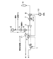
図1に、本実施の形態に係る電解質膜を有する固体電解質型改質器を備えた燃料改質システムの構成の一例を示す。ここでは先ず、燃料改質ガス循環ラインへの燃料導入段階から説明する。
都市ガス13A等の燃料は、通常室温にてシステムラインに導入されると、燃料再循環用ファン6に送られてから、燃料再生熱交換器4に送られて温度上昇する。そこから更に、図中の※1から燃料高温熱交換器7に送られて約900〜1200℃程度に温度上昇する。この高温になった燃料が、図1中の※2から固体電解質型改質器1に導入される。低温の燃料を固体電解質改質器1に導入すると、改質器1は動作しなくなるため、このように2段階の熱交換器を介すことによって高温にして流通させる方式が有効である。本発明では、システム中で発生する熱エネルギーを効果的に利用して、固体電解質膜を有する改質器1に導入される燃料ガス(メタン等)を高温(約1000℃)にする。
【0015】
固体電解質改質器1によって発生した水素および一酸化炭素を含有する改質ガスは、その一部が後流に設けられた燃焼器2に投入され、その他の改質ガスは、燃料再生熱交換器4に送られる。ここで燃焼器2に送られる改質ガスの割合は特に限定されず、燃焼に必要な分だけのガス量であればよいが、例えば発生した改質ガスの通常1〜10容量%好ましくは4〜8容量%である。
燃料再生熱交換器4における熱交換によって冷却されたガスは、さらに後流の凝縮器5によって水分除去される。このように冷却された水素を含有する改質ガスの一部が、製品としてラインから取り出される。その他の改質ガスは、再び燃料改質ガス循環ラインに流されて、新たに投入された燃料とともに、燃料再循環用エジェクタ駆動ファン6に送られる。これは固体電解質型改質器1では、電解質膜20を透過した酸素と反応する燃料の量に一定の限界があるので、一旦改質器1を流通したガスについても、再度流通させることにより、一定以上の割合で改質が行われた高濃度の水素含有ガスとして取り出すためである。
ここで、システムを流通するガスラインから生成品として取り出される改質ガスの割合は、燃料の種類や運転条件等によって任意に定められるものであり特に限定されるものではない。具体的には、メタン燃料で連続運転を行う場合、取り出される改質ガスの割合は流通する改質ガスの通常5〜30容量%程度である。
【0016】
次に、燃料改質ガス循環ラインから分岐して、燃焼器2へ導入される改質ガスについて説明する。
固体電解質改質器1によって発生した改質ガスの一部は、後流に設けられた燃焼器2に投入して燃焼されて、この燃焼器2で生じる熱エネルギーがシステム全体の熱源として利用される。燃焼器2に投入される改質ガスの一部は、空気側の排気されたガスと共に燃焼して高温になった後、燃料高温熱交換器7に送られて燃料ガスを温度上昇するために利用される。よって、燃焼器2に送られる改質ガスの割合は、改質器1から生成したガスの通常1〜10容量%程度、好ましくは4〜8容量%程度である。燃焼器2から排出されるガスは、さらに空気低温熱交換器8に送られて、常温の空気を温度上昇するために利用されてから、排気設備9から大気中に放出される。
【0017】
次に、固体電解質型改質器1に送られる空気等の酸素含有ガスの供給について説明する。
本実施の形態では上記燃料ガスと同様に、固体電解質膜20を有する改質器1へ、通常約800℃以上1300℃以下、好ましくは900〜1100℃の高温にした空気を導入する。そのため、システム中で発生する熱エネルギーを効果的に利用して、固体電解質膜を有する改質器1に導入される空気へ熱移動させる。具体的には、空気ファン10からシステム中の空気ラインに導入された空気は、空気低温熱交換器8にて廃熱を利用して温められる。次いで、空気高温熱交換器3へ導入されて、約800℃以上1300℃以下の高温ガスとした後、改質器1に導入される。改質器1において、膜を酸素分の一部、例えば0.01〜50容量%が透過して改質反応に用いられ、窒素分の全部と残りの酸素分とが改質器1から排気される。これらは、空気高温熱交換器3にて冷却された後、燃焼器2に導入される。
【0018】
なお、上述したように本発明の改質システムでは、部分酸化反応を起こさせることが好ましいが、燃料ガスの流量調整や装置内の温度等との関係によって、水が生成すると燃料改質ガス循環ラインに流通して、改質器1では、生成した水がメタンと反応して水蒸気改質反応が生じる。
CH4+3H2O→CO+3H2+2H2O
このような反応が併発することは、製品として取り出される改質ガスの水素含有量を不安低下させる要因になるとともに、効率的な改質ができないこととなるので好ましくない。このため、必要に応じて本実施の形態のように、燃料改質ガス循環ラインから改質ガスを取り出す前段に、改質ガス中の水分を凝縮除去する、凝縮器5を備えることが好ましい。
【0019】
また、固体電解質型改質器1としては固体電解質膜20を1以上有する装置であれば、種々の形態の装置を用いることができ、特に限定されるものではないが、例えば平板を積層したもの、あるいは円筒状のもの、など燃料電池の分野で一般的な装置を使用することができる。このような改質器1においては、膜上あるいは膜近傍での改質反応によって水素を製造するとともに、空気側から酸素のみを選択的に透過させる。さらに、改質器1においても発電効率を向上させるために、2枚以上の固体電解質膜20を積層させた構造、あるいは、固体電解質膜20を並列に連結させた構造、等によって一定以上の電力を得るようにした態様も可能である。
【0020】
実施の形態(その2)
図2に、本実施の形態に係る燃料改質システムの構成の他の一例を示す。
本実施の形態では、燃料改質ガス循環ラインに燃料再循環エジェクタ11を設けて、固体電解質型改質器1にて発生した直後の改質ガスの一部を、燃料高温熱交換器7に送る。本形態は、燃料再循環エジェクタ11を用いて、改質ガスを高温ガスの状態のまま循環させることにより、改質反応を促進する態様である。これによって、固体電解質型改質器1が一層高温状態を維持し易くなり、改質反応が進行しやすくなる。
【0021】
実施の形態(その3)
図3に、本実施の形態に係る燃料改質システムの構成の他の一例を示す。
本実施の形態では、酸素含有ガスの供給ラインに空気再循環エジェクタ12を設けて、固体電解質型改質器1より排出された直後の酸素含有ガスの一部を、再び固体電解質型改質器1に送る。本形態では、上記燃料再循環エジェクタ11に加えて、さらに空気も高温ガスとして再循環させることにより、熱損失を低減するとともに、酸素の利用効率を高めたものである。
【0022】
実施の形態(その4)
図4に、本実施の形態に係る燃料改質システムの構成の他の一例を示す。実施の形態(その3)のシステムに加えて、排ガス系統に排熱蒸気発生器13を追加し、発生蒸気を燃料循環系に添加して改質効率を増加させた態様である。
本実施の形態では、燃焼器2の後流にて高温ガスから、外部から導入する水へ熱移動する、排熱蒸気発生器13を設け、発生した蒸気を燃料ガスと共に燃料改質ガス循環ラインに供給する。蒸気の循環ラインへの投入時期は特に限定されないが、燃料再生熱交換器4の前段にて燃料ガスと混合して、共に2段の熱交換器にて温度上昇させる態様が好適である。
以上、本発明の実施の形態につき述べたが、本発明は既述の実施の形態に限定されるものではなく、本発明の要旨を逸脱しない範囲内において種々の変形及び変更を加え得るものである。
【0023】
【発明の効果】
本発明によれば、改質触媒に燃料を流通させる水蒸気改質法や部分酸化法に比べて、本発明の固体電解質膜を用いる方法によれば、生成する改質ガスの水素濃度を高く維持することができる。
水蒸気改質法を用いた改質装置等に比べて、装置をコンパクトにできる。
さらに、燃料電池システムの一部として用いた場合には、本改質システムからも電気を取り出して発電することができるので、同量の燃料ガスを用いた際の発電効率が向上する。
【図面の簡単な説明】
【図1】 実施の形態(その1)に係るシステムの概略構成を示した図である。
【図2】 実施の形態(その2)に係るシステムの概略構成を示した図である。
【図3】 実施の形態(その3)に係るシステムの概略構成を示した図である。
【図4】 実施の形態(その4)に係るシステムの概略構成を示した図である。
【図5】 固体電解質膜を用いた場合の水素発生の原理を模式的に示した図である。
【図6】 改質触媒を用いた改質反応を模式的に示した図である。
【符号の説明】
1 固体電解質型改質器
2 燃焼器
3 空気高温熱交換器
4 燃料再生熱交換器
5 凝縮器
6 燃料再循環用ファン
7 燃料高温熱交換器
8 空気低温熱交換器
9 煙突
10 空気ファン
11 燃料再循環エジェクタ
12 空気再循環エジェクタ
13 排熱蒸気発生器
20 固体電解質膜
21 改質触媒[0001]
BACKGROUND OF THE INVENTION
The present invention relates to a fuel reforming system using a solid electrolyte membrane, and is particularly suitable for use as a reforming system in the previous stage of a fuel cell system, which produces hydrogen from fuel such as methane with high efficiency and simultaneously generates power. The present invention relates to a fuel reforming system that is capable of operating.
[0002]
[Prior art]
In a fuel cell system, how to supply hydrogen, which is a main fuel to be sent to the fuel cell body, is an important problem. It is not practical to use hydrogen gas as a raw material for a fuel cell system as it is because the operation cost of the system is enormous, and it is practical to use a reformed gas produced from hydrocarbons.
At present, the most promising method is to produce and supply hydrogen by a reformer using methane, methanol or the like as a raw material. A specific example of a chemical reaction apparatus for reforming known so far is shown in FIG.
[0003]
In order to produce hydrogen from fuel, there is a method of reforming by a partial oxidation method as shown in FIG. In this method, methane and air are circulated through the reforming
[0004]
Further, there is a method of reforming by a steam reforming method as shown in FIG. In this method, methane and water are passed through the reforming
However, in order to perform this reforming method, it is necessary to raise the temperature of the fuel to about 1000 ° C., and the size of the apparatus increases with temperature control, and a catalyst and a corrosion-resistant metal are required. was there. Further, the hydrogen content of the produced reformed gas is usually about 50 to 60%, which is not yet a sufficient level as the fuel gas for the fuel cell. Furthermore, in a system in which the fuel is heated to a high temperature using a heat heater or the like, the operation cost is high and it is not realistic, and it is difficult to effectively use the heat energy generated in the system, which is not an efficient method.
[0005]
[Problems to be solved by the invention]
In view of the above problems, the present inventors have a high concentration reformed gas that is a fuel for fuel cells with less energy loss of the reforming system compared to reforming catalyst devices in the steam reforming method and the partial oxidation method. At the same time, we have intensively studied to develop a fuel reforming method that can improve power generation efficiency.
As a result, the present inventors use the reformer having a solid electrolyte membrane and effectively utilize the heat energy generated in the system to increase the temperature of the introduced fuel gas. Has been found to be resolved. In the present invention, a part of the reformed gas generated by the reformer is used for combustion for increasing the temperature of the fuel, so that the generated thermal energy is effectively used to achieve extremely efficient and continuous. The reformed gas can be generated. In addition, when fuel reforming is performed using this system, power generation efficiency can be greatly improved because power can be generated at the front stage of the fuel cell system in which hydrogen and oxygen are supplied to the battery body to extract electricity. . The present invention has been completed from such a viewpoint.
[0006]
[Means for Solving the Problems]
That is, the present invention is a solid electrolyte type modified type in which a reformed gas is generated on the fuel side of a solid electrolyte membrane by flowing a fuel gas on one side of the solid electrolyte membrane and an oxygen-containing gas on the other side. The combustor and a part of the reformed gas are burned to generate a high-temperature gas, and the heat is transferred from the combustor and the high-temperature gas generated in the combustor to the fuel gas before being introduced into the solid electrolyte reformer. Fuel high temperature heat exchanger and air high temperature heat exchanger that transfers heat from the high temperature oxygen-containing gas discharged from the solid electrolyte reformer to the oxygen-containing gas before introduction into the reformer , and the solid electrolyte type reformer Fuel reformed gas circulation in which part of the reformed gas generated from the gasifier is sent to the combustor and other reformed gas is circulated together with the fuel gas introduced from the outside and supplied to the solid oxide reformer again. And a fuel reforming system characterized by comprising: It is intended to provide.
In the combustor, a part of the reformed gas is introduced and an oxygen-containing gas is introduced and fueled. At this time, it is preferable from the viewpoint of the efficiency of the entire system to use the oxygen-containing gas discharged from the reformer cooled by the high-temperature air heat exchanger .
[0007]
Here, when the reformed gas is obtained as a hydrogen-containing product, the reformed gas discharged from the solid oxide reformer is further converted into fuel gas in the preceding stage of the fuel high-temperature heat exchanger in addition to the above system. It is preferable to include a fuel regeneration heat exchanger that transfers thermal energy. As a result, when the reformed gas is taken out from the fuel reformed gas circulation line as a product, the temperature of the taken out reformed gas can be sufficiently cooled, and the thermal energy at that time can be replaced with new fuel gas. In addition, it can be used to increase the temperature of the fuel reformed gas whose temperature has decreased. When using the high-temperature reformed gas as it is, for example, when using the fuel reforming system connected to the fuel cell system, it is not necessary to incorporate such a fuel regeneration heat exchanger in the system. It is preferable that the reformed gas is allowed to flow down to the subsequent fuel cell main body.
In the present invention, further addition to the system, from the hot gas discharged from the fuel high-temperature heat exchanger, to heat transfer to the air-containing gas before stream comprising a high temperature in high-temperature air heat exchanger, an air low-temperature heat exchanger Can be included. Similarly, in addition, a condenser for condensing and removing moisture in the reformed gas may be included in a stage before taking out the reformed gas from the fuel reformed gas circulation line.
[0008]
The present invention also provides a fuel cell system for supplying a fuel cell main body after reforming the fuel gas into a hydrogen-containing gas, wherein the fuel gas is reformed using any one of the fuel reforming systems described above. It is another object of the present invention to provide a fuel cell system characterized in that after the hydrogen-containing gas is used, the hydrogen-containing gas is introduced from the hydrogen gas supply unit of the solid polymer membrane fuel cell main body to generate power.
Since the solid electrolyte reformer can generate electric power as the fuel gas is reformed, it can generate electric power in the reforming stage separately from the electric power generated by the fuel cell main body. Therefore, by providing the fuel reforming system in the front stage of the fuel cell main body, two-stage power generation combined with power generation in the fuel cell main body is possible, and the power generation efficiency of the entire fuel cell system is remarkably improved. Can do.
[0009]
Thus, according to the system of the present invention, the fuel gas of the fuel cell can be produced as the reformed gas containing hydrogen, and electricity can also be generated.
Suitable fuels include gases containing hydrocarbons such as methane, propane and butane, or alcohols such as methanol and ethanol. These are reformed by a solid electrolyte reformer to generate hydrogen gas that serves as a power generation raw material for the fuel cell body.
[0010]
In the present invention, as shown in FIG. 5, by using a
That is, the
Examples of the
[0011]
When air is used as the oxygen-containing gas, most of the nitrogen gas is used. Therefore, if the reaction is performed without using the
[0012]
In addition, a partial oxidation reaction (incomplete combustion reaction) and a complete combustion reaction coexist in the combustion reaction between methane CH 4 as a fuel and oxygen O 2 as follows.
2CH 4 + O 2 → 2CO + 4H 2 (partial oxidation reaction)
CH 4 + 2O 2 → CO 2 + 2H 2 O [2CH 4 + 2H 2 O → 2CO + 6H 2 ] (complete combustion reaction)
Since the
[0013]
For this reason, in the
At the same time, the movement of ions occurs in the
[0014]
DETAILED DESCRIPTION OF THE INVENTION
Hereinafter, the present invention will be described in detail based on embodiments with reference to the accompanying drawings.
Embodiment (Part 1)
FIG. 1 shows an example of a configuration of a fuel reforming system including a solid electrolyte reformer having an electrolyte membrane according to the present embodiment. First, the fuel introduction stage to the fuel reformed gas circulation line will be described.
When fuel such as city gas 13A is introduced into the system line at normal room temperature, it is sent to the
[0015]
A part of the reformed gas containing hydrogen and carbon monoxide generated by the
The gas cooled by the heat exchange in the fuel
Here, the ratio of the reformed gas taken out as a product from the gas line flowing through the system is arbitrarily determined depending on the type of fuel, operating conditions, etc., and is not particularly limited. Specifically, when continuous operation is performed with methane fuel, the ratio of the reformed gas taken out is usually about 5 to 30% by volume of the reformed gas flowing.
[0016]
Next, the reformed gas branched from the fuel reformed gas circulation line and introduced into the
A part of the reformed gas generated by the
[0017]
Next, supply of oxygen-containing gas such as air sent to the
In the present embodiment, similarly to the fuel gas, air having a high temperature of about 800 ° C. to 1300 ° C., preferably 900 to 1100 ° C. is introduced into the
[0018]
As described above, in the reforming system of the present invention, it is preferable to cause a partial oxidation reaction. However, if water is generated due to the flow rate adjustment of the fuel gas, the temperature in the apparatus, or the like, the fuel reforming gas circulation In the
CH 4 + 3H 2 O → CO + 3H 2 + 2H 2 O
It is not preferable that such reactions occur at the same time because it causes anxiety reduction in the hydrogen content of the reformed gas taken out as a product, and efficient reforming cannot be performed. For this reason, it is preferable to provide a
[0019]
Further, as the
[0020]
Embodiment (2)
FIG. 2 shows another example of the configuration of the fuel reforming system according to the present embodiment.
In the present embodiment, a
[0021]
Embodiment (Part 3)
FIG. 3 shows another example of the configuration of the fuel reforming system according to the present embodiment.
In the present embodiment, an
[0022]
Embodiment (part 4)
FIG. 4 shows another example of the configuration of the fuel reforming system according to the present embodiment. In addition to the system of the third embodiment (No. 3), an exhaust heat steam generator 13 is added to the exhaust gas system, and the generated steam is added to the fuel circulation system to increase the reforming efficiency.
In the present embodiment, an exhaust heat steam generator 13 is provided which heat-transfers from a high-temperature gas to water introduced from the outside in the downstream of the
Although the embodiments of the present invention have been described above, the present invention is not limited to the above-described embodiments, and various modifications and changes can be made without departing from the scope of the present invention. is there.
[0023]
【The invention's effect】
According to the present invention, compared with the steam reforming method and the partial oxidation method in which fuel is circulated through the reforming catalyst, the method using the solid electrolyte membrane of the present invention maintains the hydrogen concentration of the reformed gas to be generated high. can do.
The apparatus can be made more compact than a reformer using a steam reforming method.
Furthermore, when used as part of the fuel cell system, electricity can be generated by taking out electricity from the reforming system, so that the power generation efficiency when the same amount of fuel gas is used is improved.
[Brief description of the drawings]
FIG. 1 is a diagram showing a schematic configuration of a system according to an embodiment (part 1);
FIG. 2 is a diagram showing a schematic configuration of a system according to an embodiment (part 2);
FIG. 3 is a diagram showing a schematic configuration of a system according to an embodiment (part 3);
FIG. 4 is a diagram showing a schematic configuration of a system according to an embodiment (part 4);
FIG. 5 is a diagram schematically showing the principle of hydrogen generation when a solid electrolyte membrane is used.
FIG. 6 is a diagram schematically showing a reforming reaction using a reforming catalyst.
[Explanation of symbols]
DESCRIPTION OF
Claims (8)
前記改質ガスの一部を燃焼させて高温ガスを発生させる、燃焼器と、
前記燃焼器で発生した高温ガスから、前記固体電解質型改質器に導入前の燃料ガスへ熱移動させる、燃料高温熱交換器と、
前記固体電解質型改質器より排出される高温の酸素含有ガスから、前記改質器に導入前の酸素含有ガスへ熱移動させる、空気高温熱交換器と、
前記固体電解質型改質器から発生した改質ガスの一部を前記燃焼器へ送り、他の改質ガスを外部から導入する燃料ガスと共に流通させて、再び固体電解質型改質器に供給させる、燃料改質ガス循環ラインと、
を含むことを特徴とする燃料改質システム。A solid electrolyte reformer for generating a reformed gas on the fuel side of the solid electrolyte membrane by flowing a fuel gas on one side of the solid electrolyte membrane and an oxygen-containing gas on the other side;
A combustor for burning a part of the reformed gas to generate a high-temperature gas;
A fuel high-temperature heat exchanger for transferring heat from the high-temperature gas generated in the combustor to the fuel gas before being introduced into the solid electrolyte reformer;
An air high-temperature heat exchanger for transferring heat from a high-temperature oxygen-containing gas discharged from the solid electrolyte reformer to an oxygen-containing gas before being introduced into the reformer;
A part of the reformed gas generated from the solid electrolyte reformer is sent to the combustor, and other reformed gases are circulated together with the fuel gas introduced from the outside, and supplied to the solid electrolyte reformer again. , Fuel reforming gas circulation line,
A fuel reforming system comprising:
請求項1〜7のいずれかに記載の燃料改質システムを用いて、燃料ガスを改質して水素含有ガスとした後、固体高分子膜型燃料電池本体の水素ガス供給部より該水素含有ガスを導入して発電を行うことを特徴とする燃料電池システム。A fuel cell system for reforming a fuel gas into a hydrogen-containing gas and supplying the fuel gas to a fuel cell body,
The fuel reforming system according to any one of claims 1 to 7, wherein the fuel gas is reformed to form a hydrogen-containing gas, and then the hydrogen-containing gas is supplied from a hydrogen gas supply unit of the solid polymer membrane fuel cell main body. A fuel cell system for generating power by introducing gas.
Priority Applications (1)
| Application Number | Priority Date | Filing Date | Title |
|---|---|---|---|
| JP2001219258A JP3969976B2 (en) | 2001-07-19 | 2001-07-19 | Fuel reforming system and fuel cell system |
Applications Claiming Priority (1)
| Application Number | Priority Date | Filing Date | Title |
|---|---|---|---|
| JP2001219258A JP3969976B2 (en) | 2001-07-19 | 2001-07-19 | Fuel reforming system and fuel cell system |
Publications (2)
| Publication Number | Publication Date |
|---|---|
| JP2003034501A JP2003034501A (en) | 2003-02-07 |
| JP3969976B2 true JP3969976B2 (en) | 2007-09-05 |
Family
ID=19053292
Family Applications (1)
| Application Number | Title | Priority Date | Filing Date |
|---|---|---|---|
| JP2001219258A Expired - Fee Related JP3969976B2 (en) | 2001-07-19 | 2001-07-19 | Fuel reforming system and fuel cell system |
Country Status (1)
| Country | Link |
|---|---|
| JP (1) | JP3969976B2 (en) |
-
2001
- 2001-07-19 JP JP2001219258A patent/JP3969976B2/en not_active Expired - Fee Related
Also Published As
| Publication number | Publication date |
|---|---|
| JP2003034501A (en) | 2003-02-07 |
Similar Documents
| Publication | Publication Date | Title |
|---|---|---|
| JP5405486B2 (en) | Fuel cell system | |
| US20080241638A1 (en) | SOFC system producing reduced atmospheric carbon dioxide using a molten carbonated carbon dioxide pump | |
| JP2011508949A5 (en) | ||
| JP4450623B2 (en) | Fuel cell system | |
| JP3530413B2 (en) | Fuel cell power generation system and operation method thereof | |
| JPH07230816A (en) | Internally modified solid electrolyte fuel cell system | |
| JP3943405B2 (en) | Fuel cell power generation system | |
| JP3960002B2 (en) | Fuel cell system | |
| JPH07230819A (en) | Internally modified solid electrolyte fuel cell system having self-heat exchange type heat insulating prereformer | |
| JP2001313053A (en) | Fuel cell system | |
| JP2008282599A (en) | Fuel-cell electric power generation system using methanol/dimethyl ether as material | |
| JP3969976B2 (en) | Fuel reforming system and fuel cell system | |
| JP2004199997A (en) | Hydrogen utilizing system that uses solid oxide fuel cell | |
| JP4590872B2 (en) | Operation method of fuel cell power generator | |
| JPH065298A (en) | Fuel cell power generating apparatus | |
| JP2009176659A (en) | Fuel cell generation system and its control method | |
| JP4176130B2 (en) | Fuel cell power generation system | |
| JP3837662B2 (en) | FUEL CELL POWER GENERATOR AND METHOD OF OPERATING FUEL CELL POWER GENERATOR | |
| JP2004189510A (en) | Reforming system, operation method of the same and fuel cell system and operation method of the same | |
| JP2003272677A (en) | Solid oxide type fuel cell and cogeneration system using the same | |
| JP6677458B2 (en) | System and method for power generation using series fuel cells | |
| JP2004119214A (en) | Fuel cell system | |
| JP4166561B2 (en) | Fuel cell power generation system | |
| KR101295237B1 (en) | Fuel cell system | |
| CN113471492B (en) | Fuel cell power generation system and power generation method using solid waste synthesis gas |
Legal Events
| Date | Code | Title | Description |
|---|---|---|---|
| A621 | Written request for application examination |
Free format text: JAPANESE INTERMEDIATE CODE: A621 Effective date: 20040510 |
|
| A977 | Report on retrieval |
Free format text: JAPANESE INTERMEDIATE CODE: A971007 Effective date: 20061220 |
|
| A131 | Notification of reasons for refusal |
Free format text: JAPANESE INTERMEDIATE CODE: A131 Effective date: 20061222 |
|
| A521 | Written amendment |
Free format text: JAPANESE INTERMEDIATE CODE: A523 Effective date: 20070216 |
|
| A131 | Notification of reasons for refusal |
Free format text: JAPANESE INTERMEDIATE CODE: A131 Effective date: 20070316 |
|
| A521 | Written amendment |
Free format text: JAPANESE INTERMEDIATE CODE: A523 Effective date: 20070418 |
|
| TRDD | Decision of grant or rejection written | ||
| A01 | Written decision to grant a patent or to grant a registration (utility model) |
Free format text: JAPANESE INTERMEDIATE CODE: A01 Effective date: 20070515 |
|
| A61 | First payment of annual fees (during grant procedure) |
Free format text: JAPANESE INTERMEDIATE CODE: A61 Effective date: 20070605 |
|
| R151 | Written notification of patent or utility model registration |
Ref document number: 3969976 Country of ref document: JP Free format text: JAPANESE INTERMEDIATE CODE: R151 |
|
| FPAY | Renewal fee payment (event date is renewal date of database) |
Free format text: PAYMENT UNTIL: 20100615 Year of fee payment: 3 |
|
| FPAY | Renewal fee payment (event date is renewal date of database) |
Free format text: PAYMENT UNTIL: 20100615 Year of fee payment: 3 |
|
| FPAY | Renewal fee payment (event date is renewal date of database) |
Free format text: PAYMENT UNTIL: 20110615 Year of fee payment: 4 |
|
| FPAY | Renewal fee payment (event date is renewal date of database) |
Free format text: PAYMENT UNTIL: 20110615 Year of fee payment: 4 |
|
| FPAY | Renewal fee payment (event date is renewal date of database) |
Free format text: PAYMENT UNTIL: 20120615 Year of fee payment: 5 |
|
| FPAY | Renewal fee payment (event date is renewal date of database) |
Free format text: PAYMENT UNTIL: 20130615 Year of fee payment: 6 |
|
| R250 | Receipt of annual fees |
Free format text: JAPANESE INTERMEDIATE CODE: R250 |
|
| LAPS | Cancellation because of no payment of annual fees |