JP3967971B2 - Car seat recliner - Google Patents
Car seat recliner Download PDFInfo
- Publication number
- JP3967971B2 JP3967971B2 JP2002193151A JP2002193151A JP3967971B2 JP 3967971 B2 JP3967971 B2 JP 3967971B2 JP 2002193151 A JP2002193151 A JP 2002193151A JP 2002193151 A JP2002193151 A JP 2002193151A JP 3967971 B2 JP3967971 B2 JP 3967971B2
- Authority
- JP
- Japan
- Prior art keywords
- wedge
- arc
- gear
- peripheral surface
- wedge plate
- Prior art date
- Legal status (The legal status is an assumption and is not a legal conclusion. Google has not performed a legal analysis and makes no representation as to the accuracy of the status listed.)
- Expired - Fee Related
Links
- 230000002093 peripheral effect Effects 0.000 claims description 34
- 230000005540 biological transmission Effects 0.000 claims description 14
- 238000005516 engineering process Methods 0.000 description 4
- 230000000669 biting effect Effects 0.000 description 3
- 230000000694 effects Effects 0.000 description 3
- 238000004519 manufacturing process Methods 0.000 description 3
- 238000000034 method Methods 0.000 description 2
- 240000000220 Panda oleosa Species 0.000 description 1
- 235000016496 Panda oleosa Nutrition 0.000 description 1
- 230000007423 decrease Effects 0.000 description 1
- 230000003247 decreasing effect Effects 0.000 description 1
- 238000006073 displacement reaction Methods 0.000 description 1
- 230000008030 elimination Effects 0.000 description 1
- 238000003379 elimination reaction Methods 0.000 description 1
- 238000003825 pressing Methods 0.000 description 1
- 238000000926 separation method Methods 0.000 description 1
Images


Classifications
-
- B—PERFORMING OPERATIONS; TRANSPORTING
- B60—VEHICLES IN GENERAL
- B60N—SEATS SPECIALLY ADAPTED FOR VEHICLES; VEHICLE PASSENGER ACCOMMODATION NOT OTHERWISE PROVIDED FOR
- B60N2/00—Seats specially adapted for vehicles; Arrangement or mounting of seats in vehicles
- B60N2/02—Seats specially adapted for vehicles; Arrangement or mounting of seats in vehicles the seat or part thereof being movable, e.g. adjustable
- B60N2/22—Seats specially adapted for vehicles; Arrangement or mounting of seats in vehicles the seat or part thereof being movable, e.g. adjustable the back-rest being adjustable
- B60N2/225—Seats specially adapted for vehicles; Arrangement or mounting of seats in vehicles the seat or part thereof being movable, e.g. adjustable the back-rest being adjustable by cycloidal or planetary mechanisms
- B60N2/2252—Seats specially adapted for vehicles; Arrangement or mounting of seats in vehicles the seat or part thereof being movable, e.g. adjustable the back-rest being adjustable by cycloidal or planetary mechanisms in which the central axis of the gearing lies inside the periphery of an orbital gear, e.g. one gear without sun gear
Landscapes
- Engineering & Computer Science (AREA)
- Aviation & Aerospace Engineering (AREA)
- Transportation (AREA)
- Mechanical Engineering (AREA)
- Chairs For Special Purposes, Such As Reclining Chairs (AREA)
Description
【0001】
【発明の属する技術分野】
本発明は、自動車シートのリクライニング装置に係り、詳しくは、一部で噛合された内歯車と、この内歯車より歯数の少ない外歯車が、噛合部位の移動により相対的に揺動回転するいわゆる差動伝動機構によりシートバックの傾倒角度を調節するリクライニング装置において、傾倒位置固定時におけるシートバックのがたつきの解消と、位置調節時における内歯車と外歯車の円滑な噛合伝動の改良に関するものである。
【0002】
【従来の技術】
自動車シートのリクライニング装置におけるバックシートの傾倒角度調節手段として、いわゆる差動伝動機構を採用している例としては、特公昭63−47443号公報に記載のものがある。
この技術は、内歯車と外歯車を軸支する回転軸(旋回軸)と偏心軸部(偏心輪)のうちの一方の歯車を軸支する偏心軸部が、この歯車の内孔と回転軸との間の空域において、回転軸と一体状の円板(連行円板)と、互いの先細り端部が反対向きに配置された2つのくさび片と、この2つのくさび片の対向幅広端部間に介設され、この両くさび片を押し離す方向に付勢するばねで構成され、しかもこれらが回転軸と直交する同一平面上に配置されているものである。
【0003】
そしてシートバックが所望傾倒角度位置で固定されている状態においては、反対向きのくさび片のそれぞれが、ばねによって円板の円周範囲(回転軸周り)と歯車の内孔の円周範囲との間に挟入して食込む方向に付勢されることにより、回転軸の中心と偏心軸部の中心が離反する方向に作用されて(偏心量が増える)、内歯車と外歯車の噛合部位における歯相互が圧接されるもので、これによりいわゆる噛合遊びによるシートバックのがたつきを解消しており、またシートバックの傾倒調節時にあっては、回転軸と共に回動する円板の突起(連行突起)がくさび片の先細り端に当接して、このくさび片をばねの付勢に抗して押動すると、これにより前記位置固定状態におけるくさび片の挟入食込みが外れて噛合部位における圧接状態が解除されて、円滑な噛合伝動状態となり、回転軸と偏心軸部の回動による内歯車と外歯車の相対的揺動回転による傾倒調節がなされる。
また、この技術に関連するものとして、特許第2756516号公報に記載の技術がある。
【0004】
【発明が解決しようとする課題】
差動伝動機構による車両用シートの傾倒角度調節手段は、シートバックの傾倒調節にあたって内歯車と外歯車の円滑な回転伝動が望まれるから、この内歯車と外歯車がバックラッシ(互いに噛み合う歯車の歯面間の遊び、以下噛合遊び)をもって噛合されている。
しかしこれは、調節後の所望傾倒位置(位置固定時)において、この噛合遊びによりシートバックが振動することとなり、更に各歯車の軸支部位の製作公差(以下軸受間隙)ともあいまって大きくがたつくこととなって着座者に不快感を与えると共に、このがたつきがシートへの衝撃荷重時に増幅されて多大な影響を与える。
【0005】
上記従来技術(特公昭63−47443号公報)はこれを解決しようとするものであり、その主要部である偏心軸部を構成する円板と、2つのくさび片及びばねを、回転軸と直交する同一平面上に配置している。
しかし円板は、回転軸と共に回動する過程においてくさび片の挟入食込み作用を解除すると共に、このくさび片を押圧しつつ回動させるものであり、これにより偏心軸部が回動状態となり軸支された歯車が回動することとなるから相応の強度を要するもので、そのためこの円板が前記回転軸に直交する同一平面上において広角な円弧角度範囲を占めることから、ばねの配設分を考慮すると1つのくさび片は、狭角な円弧角度範囲となり、従って一方端が先細り状で他方端はやや幅広となるゆるやかな円弧内側面と円弧外側面による短片状となる。
【0006】
これは、シートバックの位置固定時におけるくさび片の挟入食込み状態において、くさび片の円弧外側面部全面が歯車の内孔円周面に接しており、円弧内側面部は、1点が円板外周面(回転軸周り)に接している状態であることからすると、シートバックからの荷重が円弧内側面部の1点を介して狭い円弧角の円弧外側面部に集中することとなるために、ゆるやかな円弧短片状であるがゆえに懸念される軸方向への逃げすなわち、くさび片が収まっている前記平面から抜けようとする作用が働いて外れる恐れがある。
【0007】
またシートバックの位置調節時においては、前記くさび片の挟入食込み作用が解除され、円板の回動に伴ないくさび片も回動することによりこの偏心軸部に軸支された歯車を回動するものであるが、狭い円弧角のくさび片の円弧外側面部と歯車の内孔円周面の摺接によって回転軸と偏心軸部の偏心量を維持して回動するものであって、前記負荷重による逃げ作用ともあいまって不安定であるばかりか、2つのくさび片間に介設されたばねの伸縮度による両くさび片の接近離反によって偏心量が変動することとなり、外歯車と内歯車の適正な噛合(バックラッシ)が得られず位置調節に支障を来すもので、このことから、このくさび片は前記位置固定時及び位置調節時における狭円弧角範囲にかかる負荷と摺接とによる高面圧と摩耗増をまねくもので、動特性や耐久性が問題となり、これを解決して高強度の調整機構にするためには、くさび片を含む各部材の精度を高めると共に、装置全体を大きくする必要があるもので、生産工程や経費の増大につながる。
【0008】
そこでこの問題点の解決策として上記特許第2756516号公報に記載のものがある。
これは、前記における偏心軸部(偏心部分)が、回転軸(揺動軸)と一体状の円板(係合体)と、ばね(蓄勢器)及び2つのくさび片(楔形部分)の他に、このくさび片のそばに配置された三日月形の心合せ部分から構成されており、この偏心軸部が外歯車(一方の継手部分、外歯付き平歯車)の内孔(支持孔)により包囲されているものである。
そしてシートバックの位置固定時(不作動位置)においては、前記と同様に2つのくさび片の挟入食込み作用によりがたつき(半径方向遊び)を解消するものであるが、シートバックの位置調節時(調整運動中)は、心合せ部分によって外歯車の内孔を支持するごとく、それぞれに作用(機能)を分担させるもので、この心合せ部分の広円弧角範囲にわたる外周が内孔の内周に摺接することにより低面圧、耐摩耗をはかろうとするものである。
【0009】
しかしながらこの技術は、心合わせ部分の部材が増えることとなるために、コスト及び組付け工数などの増加を招くだけでなく、前記のごとく、くさび片と心合せ部分のそれぞれが分担する作用を良好に行ない、その機能を果すためには、回転軸回りと外歯車の内孔とに広角範囲にわたって摺接して、この外歯車を保持することとなる心合せ部分に高精度が求められるほか、実用上はこの心合せ部分とくさび片の寸法関係の僅かな誤差により所期の効果が得られないこととなるから、これら部品の精度管理が困難となり、加工、組立などにおいても不都合が生じることとなる。
【0010】
本発明は前記内歯車と外歯車とによる差動伝動機構を採用した自動車シートのリクライニング装置における課題を考慮して、偏心軸部を構成するくさび片の挟入食込みとその解除作用による、位置固定時におけるシートバックのがたつきの解消と、位置調節時における外歯車と内歯車の円滑な回転伝動と、耐荷重、耐摩耗性を備えた新たな手段を提供するものである。
【0011】
【課題を解決するための手段】
前記目的を達成する自動車シートのリクライニング装置は、内歯車と、この内歯車よりわずかに歯数の少ない外歯車が一部で噛合された状態で、回転軸と、この回転軸に対する偏心軸部により軸支された構成の差動伝動機構により、シートクッションに対してシートバックの傾倒角度を調節するリクライニング装置において、前記偏心軸部は、シートバックの位置固定時において、前記外歯車の中央孔に相当する軸受輪内周面と回転軸周りとなる前記内歯車の軸受筒外周面との間に挟入される2枚のくさび板と、この2枚のくさび板のそれぞれを、前記挟入方向である反対周方向に付勢するばね杆と、シートバックの位置調節時において、前記回転軸と共に回動して、前記位置固定時におけるくさび板の挟入状態を解除すると共に、このくさび板を伴なって回動する作動片部とを備え、しかも前記くさび板のそれぞれは、前記位置調節時において、前記軸受輪内周面に摺接する円弧外側面部と、軸受筒外周面に摺接する円弧内側面部を有する略三日月板状であって、この2枚が前記回転軸の軸線方向に重ね合わせて配設されているもので、前記くさび板は、円弧外側面部と円弧内側面部による円弧角度が、略180°又は180°以上であることを特徴とするものである。
【0012】
【発明の実施の形態】
図は本発明に係る自動車シートのリクライニング装置の一実施形態を示すもので、以下各図に基づき説明する。
【0013】
この実施形態におけるリクライニング装置は、シートクッション側のブラケットとシートバック側のブラケットとの間に介設された、いわゆる差動伝動機構により、シートクッションに対するシートバックの傾倒角度を調節するもので、この差動伝動機構は、内歯車と、この内歯車よりわずかに歯数の少ない外歯車が、回転軸と、この回転軸に対する偏心軸部により、一部で噛合された状態で回転可能に軸支され、回転軸の回転に伴なう噛合部位の旋回移動により、内歯車と外歯車を相対的に揺動回転させるものである。
【0014】
この実施形態にあっては、シートクッションC側のブラケットAに内歯車1が形成され、シートバックD側のブラケットBに内歯車1よりわずかに歯数の少ない外歯車2が形成されており、内歯車1は、回転軸3周りとなる中央部位の軸受筒1aが回転軸3に回転可能に嵌装され、外歯車2は、中央孔2aに嵌合された軸受輪2bが内歯車1の軸受筒1aを包囲する偏心軸部4に回転可能に嵌装された態様で、この内歯車1と外歯車2が一部で噛合された状態に配設されているものである。
【0015】
そして外歯車2を軸支している偏心軸部4は、内歯車1と外歯車2の歯数差に相当して偏心する内歯車1の軸受筒外周面1bと、外歯車2の軸受輪内周面2cとの間の偏心空域4aにあって、シートバックDの傾倒角度調節操作時(以下位置調節時)には内歯車1と外歯車2を、バックラッシを有する適正噛合状態とし、シートバックDの所望傾倒角度位置(以下位置固定時)では噛合部位における歯相互を圧接噛合状態にするための、作動片部3aと、2枚のくさび板5,5´及び、欠円状ばね杆6を備えているものである。
【0016】
これを位置固定状態時を示す図1、4において説明すると、前記偏心軸部4における作動片部3aは、回転軸3と一体状に形成され、軸受輪内周面2cに沿う外周側面部3bと軸受筒外周面1bに沿う内周側面部3cによる円弧角度が略150°を有する円弧鍔状であって、偏心空域4a(偏心軸部4)における偏心方向とは反対部位に配置されている。
【0017】
2枚のくさび板5,5´は同形状で、その1枚(図3)は、軸受輪内周面2c径と同径円弧状であって、この内周面2cに摺接する円弧外側面部5aと、軸受筒外周面1b径より僅かに大径な円弧状であって、この外周面1bに摺接する円弧内側面部5bを有する円弧角略180°の略三日月板状で、その略中央部位には、欠円状ばね杆6の係止孔5cと円弧孔5dが同心円上に列設されているもので、この同形のくさび板5,5´の2枚が、偏心空域4a(偏心軸部4)における偏心方向部位において、一方のくさび板5´を裏返しにした互いに逆向きの態様で、回転軸3の軸線3d方向に重ね合わせて配設されている。
【0018】
欠円状ばね杆6は、欠円部位の各端から欠円形面に対して略直角に折曲形成された脚杆部6a,6´aを有し、その一方の脚杆部6aが前記重ね合わされたくさび板5,5´のうちの手前側のくさび板5の係止孔5cに係止されていると共に奥側のくさび板5´の円弧孔5´dに挿通され、他方の脚杆部6´aは、手前側のくさび板5の円弧孔5dに挿通されていると共に奥側のくさび板5´の係止孔5´cに係止された状態で軸受輪2bの前面に沿って配置されている。
【0019】
これにより2枚のくさび板5,5´のそれぞれは、欠円状ばね杆bの拡径弾力により、係止孔5c,5´cに係止された脚杆部6a,6´aを介して互いに反対周方向に付勢されているもので、この図1,4に示す位置固定状態において、手前側のくさび板5が反時計回り方向に、奥側のくさび板5´は時計回り方向に付勢されて軸受筒外周面1bと軸受輪内周面2c間における次第に間隔が狭くなる左右両方向位のそれぞれに挟入され、各くさび板5,5´の円弧外側面部5a,5´a全面が同径である軸受輪内周面2cに接し、円弧内側面部5b,5´bは、挟入方向の略4分の3部位E,E´(接点)が軸受筒外周面1bに接した状態で食込んでおり、各くさび板5,5´の付勢方向端面部5e,5´eと作動片部3aの各端面部3eが、わずかな間隔をもって対向する状態で配装されている。
【0020】
そしてこの図1、4に示す位置固定時の状態にあっては、回転軸3周りとなる軸受筒外周面1bと外歯車2の中央孔2aに相当する軸受輪内周面2c間へのくさび板5,5´の挟入食込みによって、この両周面1b,2cすなわち、回転軸3の中心3fと偏心軸部4の中心4bが偏心方向線上において互いに離反する方向に押圧されており(偏心量増F)、これにより軸受筒1aの内周面が回転軸3の外周面に圧接されていると共に、軸受輪2b、中央孔2aを介して外歯車2と内歯車1の噛合部位における歯相互が圧接された状態になっているもので、内歯車1を軸支する回転軸3周りと、外歯車2を軸支する偏心軸部4における各軸支部位の軸受間隙(製作公差)及び回転伝動に要する適正な噛合のための噛合遊び(バックラッシ)によるシートバックDのがたつきを解消している。
【0021】
なお、前記位置固定時の状態において、くさび板5,5´の各円弧内側面部5b,5´bと軸受筒外周面1bとの接点E,E´位置は、軸受筒1a中心(回転軸3中心3f)からの伏角αが狭角の位置であると、くさび板5,5´の挟入食込み力が弱くなり、広角の位置であると僅少移動で挟入食込み及びその解除作動をすることとなるので高精度が要されることとなるから、伏角αが35°〜50°の範囲位置が適当であり、そのためには、くさび板5が径方向寸法Xにおいて、僅少ではあるが接点E部位が最大で、両端部位方向が次第に小さくなる円弧形が好適である。
【0022】
また、この実施形態においては、2枚のくさび板5,5´が同形であり、一方を裏返して使用する態様であるが、勿論これが必須ではなく、円弧角度も限定するものではない。
【0023】
前記位置固定時における状態からの傾倒位置調節は、シートバックDの所望傾倒方向(前倒、後倒)に応じて回転方向操作されたモータ(図示せず)からギヤ7を介して回転軸3を回転することによる。
例えば図4、5のごとく回転軸3が時計回り方向に回転されると、これに伴ない一体状の作動片部3aも同方向に回転して、回転方向の端面部3eが対向する一方のくさび板5の端面部5eに当接して押圧し、この押圧により欠円状ばね杆6によって挟入食込み方向に付勢されていたくさび板5が、この付勢に抗して周方向(時計回り方向)に押動されて挟入食込みが外されると共に、更に作動片部3aは他方のくさび板5´の端面部にも当接して、2枚のくさび板5,5´を重ねた状態で押動する。
【0024】
この一方のくさび板5の移動、すなわち接点Eの変位動により前記位置固定時における軸受間隙の圧接と、噛合部位の圧接噛合状態が解除され、重なったくさび板5,5´は、軸受筒1bに接する両円弧内側面部5b,5´bを介して両円弧外側面部5a,5´a全面が軸受輪内周面2cに摺接した状態となり、偏心軸部4は、内歯車1と外歯車2の円滑な回転伝動における適正な噛合遊び(バックラッシ)に要する偏心量Gを維持しつつ、作動片部3a及び欠円状ばね杆6と共に回転軸3を中心としてその回転に伴ない回転する。
【0025】
これにより、偏心軸部4に軸支された外歯車2が回転され、これに伴なう内歯車1との噛合部位の旋回移動により外歯車2が形成されたシートバックD側のブラケットBは、内歯車1が形成されたシートクッションC側ブラケットAに対して傾倒角度調節される。
【0026】
前記実施形態による自動車シートのリクライニング装置は、偏心軸部4におけるくさび板5が円弧角略180°の大きさであって、しかもこれが回転軸3の軸線3d方向に2枚(5,5´)重ね合せて配設され、シートバックDの位置固定時におけるくさび板5,5´の挟入食込み状態において、両円弧外側面部5a,5´a全面が、2枚分の厚みをもって軸受輪内周面2cに接してこれを押圧していると共にシートバックDを支持しているものであるから、内歯車1と外歯車2との噛合遊びによるがたつきの解消はもとより、シートバックDに対する衝撃荷重においても、このくさび板5,5´が、軸方向に逃げて抜ける恐れがなく安定状態で受け、しかもこの荷重が広範囲に分散されるので面圧も低くなる。また位置調節時においても前記のごとくくさび板5,5´が円弧外側面部5a,5´aの全面にわたって外歯車2の中央孔2aに相当する軸受輪内周面2cに摺接するものであるから、この調節時における荷重も分散されて摺動抵抗も少なくなり、内歯車1と外歯車2との適正な噛合遊び(バックラッシ)に要する偏心量Gを維持することができるので、シートバックDの傾倒位置調節が円滑に行なわれるもので、耐荷重、耐摩耗すなわち、動特性及び耐久性に優れた装置である。
【0027】
【発明の効果】
本発明に係る自動車シートのリクライニング装置は、偏心軸部におけるくさび板が円弧角略180°又は180°以上の大きさであって、しかもこれが回転軸の軸線方向に2枚重ね合せて配設されているものであるから、シートバックの位置固定時におけるくさび板の挟入食込み状態において、両円弧外側面部全面が、2枚分の厚みをもって軸受輪内周面に接してこれを押圧していると共にシートバックを支持していることとなるので、内歯車と外歯車との噛合遊びによるがたつきの解消はもとより、シートバックに対する衝撃荷重においても、この2枚のくさび板が、軸方向に逃げて抜ける恐れがなく安定状態で受け、しかもこの荷重が広範囲に分散されるので面圧も低くなる。また位置調節時においても前記のごとく2枚のくさび板が円弧外側面部の全面にわたって外歯車の中央孔に相当する軸受輪内周面に摺接するものであるから、この調節時における荷重も分散されて摺動抵抗も少なくなり、内歯車と外歯車との適正な噛合遊び(バックラッシ)に要する偏心量を維持することができるので、シートバックの傾倒位置調節が円滑に行なわれるもので、耐荷重、耐摩耗すなわち、動特性及び耐久性に優れたものである。
【図面の簡単な説明】
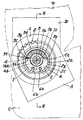
【図1】一部を切欠したリクライニング装置の正面図。
【図2】図1のZ−Z線断面図。
【図3】くさび板の正面図。
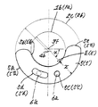
【図4】位置固定時における偏心軸部の簡略正面図。
【図5】位置調節時における偏心軸部の簡略正面図。
【符号の説明】
1 内歯車
1a 軸受筒
1b 軸受筒外周面
2 外歯車
2a 中央孔
2b 軸受輪
2c 軸受輪内周面
3 回転軸
3a 作動片部
3d 軸線
3e 端面部
3f 中心
4 偏心軸部
4a 偏心空域
4b 中心
5,5´ くさび板
5a,5´a 円弧外側面部
5b,5´b 円弧内側面部
5e,5´e 端面部
6 欠円状ばね杆
7 ギヤ
A シートクッション側ブラケット
B シートクッション側ブラケット
C シートクッション
D シートバック
E,E´ 接点
F 偏心量増
G 適正な偏心量[0001]
BACKGROUND OF THE INVENTION
The present invention relates to a reclining device for an automobile seat, and more specifically, a so-called partly engaged internal gear and an external gear having a smaller number of teeth than the internal gear are relatively oscillated and rotated by the movement of the meshing part. In a reclining device that adjusts the tilt angle of the seat back by a differential transmission mechanism, it relates to the elimination of the backlash of the seat back when the tilt position is fixed and the improvement of the smooth meshing transmission of the internal gear and the external gear at the time of position adjustment. is there.
[0002]
[Prior art]
As an example of adopting a so-called differential transmission mechanism as means for adjusting a tilt angle of a back seat in a reclining device for an automobile seat, there is one disclosed in Japanese Patent Publication No. 63-47443.
In this technology, an eccentric shaft portion that supports one of a rotation shaft (swivel shaft) and an eccentric shaft portion (eccentric ring) that supports an internal gear and an external gear is provided with an inner hole and a rotation shaft of the gear. In the airspace between the two, the rotating shaft and the integrated disk (entrained disk), the two wedge pieces with the tapered ends opposite to each other, and the opposite wide end portions of the two wedge pieces The spring is interposed between the two wedge pieces and urges the wedge pieces in the direction to push them apart, and these are arranged on the same plane perpendicular to the rotation axis.
[0003]
In the state where the seat back is fixed at the desired tilt angle position, each of the opposite wedge pieces is caused by the spring between the circumferential range of the disk (around the rotation axis) and the circumferential range of the inner hole of the gear. By being urged in the direction of sandwiching and biting, the center of the rotating shaft and the center of the eccentric shaft part are acted away from each other (the amount of eccentricity increases), and the meshing part of the internal gear and the external gear The teeth are pressed against each other, so that the backlash of the seat back due to so-called meshing play is eliminated, and when the tilt of the seat back is adjusted, the protrusion of the disk that rotates with the rotating shaft ( When the entraining protrusions abut against the tapered end of the wedge piece and push the wedge piece against the bias of the spring, this prevents the wedge piece from being caught in the fixed position and press-contacting at the meshing portion. The state is released Te becomes a smooth meshing transmission state, tilting adjustment by the relative swinging rotation of the internal gear and the external gear by the rotation of the eccentric shaft portion and the rotary shaft is made.
Further, as a technology related to this technology, there is a technology described in Japanese Patent No. 2756516.
[0004]
[Problems to be solved by the invention]
The vehicle seat tilt angle adjusting means using the differential transmission mechanism requires smooth rotation transmission of the internal gear and the external gear when adjusting the tilt of the seat back. Therefore, the internal gear and the external gear are backlashed (the gear teeth meshing with each other). It is meshed with play between faces (hereinafter referred to as mesh play).
However, at the desired tilted position after adjustment (when the position is fixed), the seat back vibrates due to this meshing play, and the manufacturing tolerance (hereinafter referred to as “bearing gap”) of the shaft support part of each gear greatly increases. This causes discomfort to the seated person, and this rattling is amplified during impact loading on the seat and has a great influence.
[0005]
The above prior art (Japanese Examined Patent Publication No. 63-47443) is intended to solve this problem, and a disc constituting the eccentric shaft portion, which is the main portion, two wedge pieces and a spring are orthogonal to the rotation axis. Are arranged on the same plane.
However, the disc releases the wedge biting action of the wedge piece in the process of rotating together with the rotating shaft, and rotates the wedge piece while pressing it. Since the supported gear rotates, it requires a certain strength. Therefore, since this disk occupies a wide arc angle range on the same plane orthogonal to the rotation axis, Therefore, one wedge piece has a narrow arc angle range, and accordingly, one end is tapered, and the other end is slightly widened by a gentle arc inner surface and an arc outer surface that are slightly wider.
[0006]
This is because, when the wedge piece is caught in the seatback position, the entire outer surface of the arc of the wedge is in contact with the circumferential surface of the inner hole of the gear. Since it is in contact with the surface (around the rotation axis), the load from the seat back is concentrated on the arc outer surface portion with a narrow arc angle via one point on the inner surface portion of the arc. There is a risk of escaping in the axial direction, which is a concern due to the short arc shape, that is, the action of trying to escape from the plane in which the wedge pieces are accommodated.
[0007]
Further, when adjusting the position of the seat back, the wedge biting action of the wedge piece is released, and the wedge piece also rotates along with the rotation of the disk, thereby rotating the gear supported on the eccentric shaft portion. Although it moves, it rotates while maintaining the eccentric amount of the rotating shaft and the eccentric shaft portion by sliding contact between the arc outer surface portion of the wedge piece with a narrow arc angle and the inner hole circumferential surface of the gear, Not only is it unstable due to the escaping action due to the load weight, but also the eccentric amount fluctuates due to the approach and separation of both wedge pieces due to the elasticity of the spring interposed between the two wedge pieces. In this case, the wedge piece is caused by the load and sliding contact applied to the narrow arc angle range when the position is fixed and when the position is adjusted. High surface pressure and increased wear So, dynamic characteristics and durability become a problem, and in order to solve this and make a high-strength adjustment mechanism, it is necessary to increase the accuracy of each member including the wedge piece and enlarge the entire device, This leads to an increase in production processes and expenses.
[0008]
Therefore, as a solution to this problem, there is one described in the above-mentioned Japanese Patent No. 2756516.
This is because the eccentric shaft portion (eccentric portion) is a disc (engagement body) integrated with the rotating shaft (oscillating shaft), a spring (accumulator), and two wedge pieces (wedge-shaped portion). In addition, it is composed of a crescent-shaped centering part arranged beside this wedge piece, and this eccentric shaft part is formed by the inner hole (support hole) of the external gear (one joint part, spur gear with external teeth) It is what is surrounded.
When the position of the seat back is fixed (non-operating position), the ratchet (radial play) is eliminated by the pinching action of the two wedge pieces in the same manner as described above. When adjusting (during the adjustment movement), the centering part shares the action (function) as if the inner hole of the external gear is supported, and the outer periphery of the centering part over the wide arc angle range is inside the inner hole. It is intended to achieve low surface pressure and wear resistance by sliding in contact with the circumference.
[0009]
However, this technique increases the number of members in the centering portion, which not only increases the cost and assembly man-hours, but also has a good effect that the wedge piece and the centering portion share as described above. In order to perform this function, high precision is required for the centering part that holds the external gear by sliding in contact with the rotation shaft and the inner hole of the external gear over a wide angle range. Above, the desired effect cannot be obtained due to a slight error in the dimensional relationship between the centering portion and the wedge piece. Therefore, it is difficult to control the accuracy of these parts, and inconveniences occur in processing and assembly. Become.
[0010]
In consideration of the problems in the reclining device for an automobile seat that employs the differential transmission mechanism using the internal gear and the external gear, the present invention fixes the position by sandwiching the wedge pieces constituting the eccentric shaft portion and releasing the wedge pieces. The present invention provides a new means that eliminates backlash of the seat back at the time, smooth rotation transmission of the external gear and the internal gear at the time of position adjustment, load resistance, and wear resistance.
[0011]
[Means for Solving the Problems]
A reclining device for an automobile seat that achieves the above-described object includes a rotating shaft and an eccentric shaft portion with respect to the rotating shaft in a state in which an internal gear and an external gear having slightly fewer teeth than the internal gear are partially engaged. In a reclining device that adjusts the tilt angle of the seat back with respect to the seat cushion by a differential transmission mechanism that is pivotally supported, the eccentric shaft portion is formed in the central hole of the external gear when the position of the seat back is fixed. Two wedge plates sandwiched between the corresponding inner peripheral surface of the bearing ring and the outer peripheral surface of the bearing cylinder of the internal gear around the rotation shaft, and the two wedge plates are respectively inserted in the inserting direction. When the position of the seat back is adjusted, the spring rod that is biased in the opposite circumferential direction is rotated together with the rotating shaft to release the wedge plate from being clamped when the position is fixed. Each of the wedge plates is in sliding contact with the outer peripheral surface of the bearing ring and the outer peripheral surface of the bearing cylinder during the position adjustment. It is a substantially crescent plate shape having an arc inner side surface portion, and these two sheets are arranged so as to overlap each other in the axial direction of the rotating shaft, and the wedge plate has an arc angle formed by the arc outer surface portion and the arc inner side surface portion. Is approximately 180 ° or 180 ° or more.
[0012]
DETAILED DESCRIPTION OF THE INVENTION
FIG. 1 shows an embodiment of an automobile seat reclining device according to the present invention, which will be described below with reference to the drawings.
[0013]
The reclining device in this embodiment adjusts the tilt angle of the seat back with respect to the seat cushion by a so-called differential transmission mechanism interposed between the bracket on the seat cushion side and the bracket on the seat back side. The differential transmission mechanism is rotatably supported in a state in which an internal gear and an external gear having a slightly smaller number of teeth than the internal gear are partially engaged by a rotating shaft and an eccentric shaft portion with respect to the rotating shaft. In addition, the internal gear and the external gear are relatively swung and rotated by the turning movement of the meshing portion accompanying the rotation of the rotation shaft.
[0014]
In this embodiment, the internal gear 1 is formed on the bracket A on the seat cushion C side, and the external gear 2 having slightly fewer teeth than the internal gear 1 is formed on the bracket B on the seat back D side, The internal gear 1 is rotatably fitted to the rotary shaft 3 with a bearing cylinder 1a at the central portion around the rotary shaft 3, and the external gear 2 has a bearing ring 2b fitted into the central hole 2a. The internal gear 1 and the external gear 2 are arranged so as to be partially engaged with each other in a manner rotatably fitted to the
[0015]
The
[0016]
1 and 4 showing the position fixed state, the operating piece portion 3a of the
[0017]
The two
[0018]
The notched
[0019]
As a result, each of the two
[0020]
1 and 4, when the position is fixed, a wedge is formed between the outer peripheral surface 1b of the bearing cylinder and the inner peripheral surface 2c of the bearing ring corresponding to the central hole 2a of the outer gear 2. By sandwiching the
[0021]
In the state at the time of fixing the position, the positions of the contacts E and E ′ between the arc
[0022]
In this embodiment, the two
[0023]
The tilt position adjustment from the state at the time of fixing the position is performed by a rotating shaft 3 via a gear 7 from a motor (not shown) operated in a rotational direction in accordance with a desired tilt direction (forward or backward) of the seat back D. By rotating.
For example, when the rotary shaft 3 is rotated in the clockwise direction as shown in FIGS. 4 and 5, the integral operating piece portion 3a is also rotated in the same direction, and one
[0024]
The movement of the one
[0025]
As a result, the external gear 2 pivotally supported by the
[0026]
In the reclining device for an automobile seat according to the above embodiment, the
[0027]
【The invention's effect】
In the reclining device for an automobile seat according to the present invention, the wedge plate in the eccentric shaft portion has a circular arc angle of approximately 180 ° or 180 ° or more, and is disposed so as to overlap two in the axial direction of the rotating shaft. Therefore, in the state where the wedge plate is sandwiched when the position of the seat back is fixed, the entire outer surfaces of both arcs are in contact with the inner peripheral surface of the bearing ring and press it with a thickness of two sheets. Since the seat back is supported at the same time, the two wedge plates escape in the axial direction not only from the backlash caused by the meshing play between the internal gear and the external gear, but also from the impact load on the seat back. The load is distributed in a wide range and the contact pressure is lowered. Even during position adjustment, the two wedge plates are in sliding contact with the inner peripheral surface of the bearing ring corresponding to the central hole of the external gear over the entire surface of the arc outer surface as described above, so that the load during this adjustment is also dispersed. The sliding resistance is also reduced, and the eccentric amount required for proper engagement play (backlash) between the internal gear and external gear can be maintained, so that the tilt position of the seat back can be adjusted smoothly and the load resistance It is excellent in wear resistance, that is, dynamic characteristics and durability.
[Brief description of the drawings]
FIG. 1 is a front view of a reclining device with a part cut away.
2 is a cross-sectional view taken along the line ZZ in FIG.
FIG. 3 is a front view of a wedge plate.
FIG. 4 is a simplified front view of an eccentric shaft portion when the position is fixed.
FIG. 5 is a simplified front view of an eccentric shaft portion during position adjustment.
[Explanation of symbols]
DESCRIPTION OF SYMBOLS 1 Internal gear 1a Bearing cylinder 1b Bearing cylinder outer peripheral surface 2 External gear 2a Center hole 2b Bearing wheel 2c Bearing wheel inner peripheral surface 3 Rotating shaft
Claims (1)
前記偏心軸部は、シートバックの位置固定時において、前記外歯車の中央孔に相当する軸受輪内周面と回転軸周りとなる前記内歯車の軸受筒外周面との間に挟入される2枚のくさび板と、
前記2枚のくさび板の一方に係止させた脚杆部と他方に係止させた脚杆部とを有するばね杆と、
シートバックの位置調節時において、前記回転軸と共に回動して、前記位置固定時におけるくさび板の挟入状態を解除すると共に、このくさび板を伴なって回動する作動片部とを備え、
しかも前記くさび板のそれぞれは、前記位置調節時において、前記軸受輪内周面に摺接する円弧外側面部と、軸受筒外周面に摺接する円弧内側面部を有する略三日月板状であって、この2枚が前記回転軸の軸線方向において手前側と奥側に重ね合わせて配設され、
ばね杆は脚杆部の一方を回転軸の軸線方向に重ね合わせた2枚のくさび板の手前側のくさび板の係止孔に係止させると共に奥側のくさび板の円弧孔に挿通させ、他方を手前側のくさび板の円弧孔に挿通させると共に奥側のくさび板の係止孔に係止させた状態で軸受輪の前面に欠円形状に配置させて2枚のくさび板を互いに反対周方向に付勢する欠円状ばね杆から構成され、
更にくさび板は、円弧外側面部と円弧内側面部による円弧角度が、少なくとも180°であることを特徴とする自動車用シートのリクライニング装置。In a state where the internal gear and the external gear having a slightly smaller number of teeth than the internal gear are partially engaged, the rotary shaft and the differential transmission mechanism supported by the eccentric shaft portion with respect to the rotary shaft, In the reclining device that adjusts the tilt angle of the seat back with respect to the seat cushion,
The eccentric shaft portion is sandwiched between the inner peripheral surface of the bearing ring corresponding to the central hole of the outer gear and the outer peripheral surface of the bearing cylinder of the inner gear around the rotation shaft when the position of the seat back is fixed. Two wedge plates,
A spring rod which chromatic and a leg rod portion which has engaged with the engaged thereby leg rod section and the other one of the two wedge plates,
When adjusting the position of the seat back, it rotates together with the rotating shaft to release the wedged state of the wedge plate at the time of fixing the position, and has an operating piece that rotates with the wedge plate,
Moreover, each of the wedge plates has a substantially crescent plate shape having an arc outer surface portion slidably contacting the bearing ring inner peripheral surface and an arc inner surface portion slidably contacting the bearing cylinder outer peripheral surface at the time of position adjustment. The sheets are arranged so as to overlap the front side and the back side in the axial direction of the rotating shaft,
The spring rod is engaged with the wedge hole on the front side of the two wedge plates, one of the leg collars overlapped in the axial direction of the rotating shaft, and inserted into the arc hole of the wedge plate on the back side, The other wedge plate is inserted into the arc hole of the wedge plate on the front side and locked in the engagement hole of the wedge plate on the back side, so that the two wedge plates are opposed to each other in the shape of a circle on the front surface of the bearing ring. Consists of a non-circular spring rod energized in the circumferential direction,
Furthermore, the wedge plate has an arc angle formed by the arc outer side surface portion and the arc inner side surface portion of at least 180 ° .
Priority Applications (6)
| Application Number | Priority Date | Filing Date | Title |
|---|---|---|---|
| JP2002193151A JP3967971B2 (en) | 2002-07-02 | 2002-07-02 | Car seat recliner |
| US10/354,976 US6755470B2 (en) | 2002-07-02 | 2003-01-31 | Seat reclining apparatus for automotive vehicle |
| GB0302466A GB2390298B (en) | 2002-07-02 | 2003-02-03 | Seat reclining apparatus for automotive vehicle |
| CN03106703.4A CN1289336C (en) | 2002-07-02 | 2003-02-27 | Seat reclining apparatus for automotive vehicle |
| FR0303393A FR2841837B1 (en) | 2002-07-02 | 2003-03-20 | SEAT INCLINATION APPARATUS FOR MOTOR VEHICLE |
| DE10321712A DE10321712B4 (en) | 2002-07-02 | 2003-05-14 | Seat adjustment device for a motor vehicle seat |
Applications Claiming Priority (1)
| Application Number | Priority Date | Filing Date | Title |
|---|---|---|---|
| JP2002193151A JP3967971B2 (en) | 2002-07-02 | 2002-07-02 | Car seat recliner |
Publications (2)
| Publication Number | Publication Date |
|---|---|
| JP2004033401A JP2004033401A (en) | 2004-02-05 |
| JP3967971B2 true JP3967971B2 (en) | 2007-08-29 |
Family
ID=19195556
Family Applications (1)
| Application Number | Title | Priority Date | Filing Date |
|---|---|---|---|
| JP2002193151A Expired - Fee Related JP3967971B2 (en) | 2002-07-02 | 2002-07-02 | Car seat recliner |
Country Status (6)
| Country | Link |
|---|---|
| US (1) | US6755470B2 (en) |
| JP (1) | JP3967971B2 (en) |
| CN (1) | CN1289336C (en) |
| DE (1) | DE10321712B4 (en) |
| FR (1) | FR2841837B1 (en) |
| GB (1) | GB2390298B (en) |
Families Citing this family (52)
| Publication number | Priority date | Publication date | Assignee | Title |
|---|---|---|---|---|
| DE10328300B4 (en) * | 2003-06-23 | 2006-09-21 | Faurecia Autositze Gmbh & Co. Kg | Adjustment fitting for motor vehicle seat |
| KR100549199B1 (en) * | 2003-11-26 | 2006-02-02 | 주식회사다스 | Reclining device for seat assembly of vehicle |
| JP2005211142A (en) * | 2004-01-27 | 2005-08-11 | Aisin Seiki Co Ltd | Angle adjustor |
| DE102004007043B3 (en) * | 2004-02-12 | 2005-06-23 | Keiper Gmbh & Co. Kg | Mounting for backrest of automobile passenger seat adjusted via driven eccentric provided by ring enclosing 2 wedge segments which are biased together |
| DE102004013272B3 (en) * | 2004-03-18 | 2006-01-26 | Faurecia Autositze Gmbh & Co. Kg | Tilt adjustment fitting for the backrest of a motor vehicle seat |
| DE102004019463A1 (en) | 2004-04-15 | 2005-11-10 | Keiper Gmbh & Co.Kg | Drive unit for a vehicle seat |
| DE102004019466B4 (en) | 2004-04-15 | 2006-07-13 | Keiper Gmbh & Co.Kg | Adjustment device for a vehicle seat |
| DE102004019465B4 (en) * | 2004-04-15 | 2014-01-23 | Keiper Gmbh & Co. Kg | Drive unit for a vehicle seat |
| DE102004019469A1 (en) * | 2004-04-15 | 2005-11-10 | Keiper Gmbh & Co.Kg | Drive unit in a vehicle |
| DE102004019471B4 (en) * | 2004-04-15 | 2014-01-02 | Keiper Gmbh & Co. Kg | Drive unit for a vehicle seat |
| JP4545523B2 (en) * | 2004-08-23 | 2010-09-15 | 株式会社今仙電機製作所 | Reclining device |
| JP4538289B2 (en) * | 2004-09-29 | 2010-09-08 | 富士機工株式会社 | Car seat recliner |
| US7086699B1 (en) | 2004-12-21 | 2006-08-08 | Dura Global Technologies, Inc. | Recliner assembly for vehicle seats |
| JP4928767B2 (en) * | 2004-12-28 | 2012-05-09 | デルタ工業株式会社 | Bracket angle adjustment device |
| CN100484802C (en) * | 2004-12-28 | 2009-05-06 | 德鱼塔工业股份有限公司 | Bracket angle adjustment mechanism |
| JP4676756B2 (en) * | 2004-12-28 | 2011-04-27 | デルタ工業株式会社 | Bracket angle adjustment device |
| WO2006088896A1 (en) * | 2005-02-16 | 2006-08-24 | Johnson Controls Technology Company | Seat recliner |
| DE102005026658B3 (en) * | 2005-06-09 | 2006-11-02 | Faurecia Autositze Gmbh & Co. Kg | Inclination adjustment fitting for vehicle seat, has contact cam serving for load transmission, over larger contact surface of cam, from fitting part connected with backrest onto another fitting part connected with seat part |
| JP4667167B2 (en) * | 2005-08-23 | 2011-04-06 | 株式会社今仙電機製作所 | Smooth tilting actuator in the reclining mechanism of an automobile seat |
| JP4684807B2 (en) * | 2005-08-29 | 2011-05-18 | 株式会社今仙電機製作所 | Reclining unit for automobile seat |
| JP4895084B2 (en) * | 2005-09-15 | 2012-03-14 | アイシン精機株式会社 | Seat reclining device |
| JP2007117233A (en) * | 2005-10-26 | 2007-05-17 | Delta Kogyo Co Ltd | Bracket angle adjuster |
| GB2449383B (en) * | 2006-02-16 | 2010-07-14 | Imasen Electric Ind | Reclining device |
| JP2007268251A (en) * | 2006-03-10 | 2007-10-18 | Ntn Corp | Reclining device for seat |
| JP2008006265A (en) * | 2006-05-30 | 2008-01-17 | Ntn Corp | Reclining device for seat |
| US7878594B2 (en) | 2006-03-10 | 2011-02-01 | Ntn Corporation | Seat reclining device |
| JP5023532B2 (en) * | 2006-03-27 | 2012-09-12 | アイシン精機株式会社 | Sheet adjustment device |
| CN101070055B (en) | 2006-05-11 | 2011-06-08 | 湖北中航精机科技股份有限公司 | Gear-type chair angle stepless regulation structure |
| US7513573B2 (en) * | 2006-09-12 | 2009-04-07 | Lear Corporation | Continuous recliner |
| US7517021B2 (en) * | 2006-09-12 | 2009-04-14 | Lear Corporation | Reclining mechanism for vehicle seats |
| US8460145B2 (en) * | 2007-06-11 | 2013-06-11 | Toyota Boshoku Kabushiki Kaisha | Rotation mechanism |
| JP2009207702A (en) | 2008-03-05 | 2009-09-17 | Fuji Kiko Co Ltd | Automotive seat reclining device |
| JP5393990B2 (en) * | 2008-04-01 | 2014-01-22 | デルタ工業株式会社 | Seat reclining device |
| JP5514445B2 (en) | 2009-01-07 | 2014-06-04 | Ntn株式会社 | Bearing bush for seat reclining device and seat reclining device |
| BRPI0920491B1 (en) * | 2009-03-05 | 2019-09-17 | Lear Corporation | RECLINING MECHANISM FOR A VEHICLE SEAT THAT IS CONNECTED TO A SECOND AXLE RECLINING MECHANISM, RECLINING SYSTEM FOR USE IN A VEHICLE AND SEAT ASSEMBLY FOR USE IN A VEHICLE |
| JP5532690B2 (en) * | 2009-06-09 | 2014-06-25 | アイシン精機株式会社 | Vehicle seat reclining device |
| CN101941389B (en) * | 2009-07-04 | 2012-06-20 | 湖北中航精机科技股份有限公司 | Seat angle adjuster and seat with angle adjuster |
| DE102009053250B4 (en) * | 2009-11-10 | 2013-04-04 | Keiper Gmbh & Co. Kg | Fitting for a vehicle seat and vehicle seat |
| DE102009060344A1 (en) * | 2009-12-24 | 2011-06-30 | Sitech Sitztechnik GmbH, 38442 | Adjustment fitting for adjusting inclination of backrest of motor vehicle seat relative to seat part, has wedge segments in direct or indirect connection by damping element to damp relative movements of segments relative to each other |
| DE102011115706B4 (en) | 2010-10-20 | 2022-08-11 | Sitech Sitztechnik Gmbh | adjustable fitting |
| DE102011051990A1 (en) * | 2011-07-20 | 2013-01-24 | C. Rob. Hammerstein Gmbh & Co. Kg | Seat fitting for a motor vehicle seat |
| JP2013112063A (en) * | 2011-11-25 | 2013-06-10 | Delta Kogyo Co Ltd | Reclining device |
| JP2013170649A (en) * | 2012-02-22 | 2013-09-02 | Shiroki Corp | Reduction gear mechanism |
| US9167898B2 (en) | 2012-10-04 | 2015-10-27 | Lear Corporation | Recliner mechanism having a brake |
| US9475409B2 (en) * | 2013-06-17 | 2016-10-25 | Hubei Aviation Precision Machinery Technology Co., Ltd. | Seat recliner and oil collecting element |
| DE102014208076A1 (en) * | 2013-10-23 | 2015-05-07 | Johnson Controls Components Gmbh & Co. Kg | Electrically operated backrest adjuster and vehicle seat with such a backrest adjuster |
| US10421375B2 (en) * | 2016-11-17 | 2019-09-24 | Shiroki Corporation | Reclining device |
| US10640010B2 (en) * | 2016-12-29 | 2020-05-05 | Lear Corporation | Adjustable seat assembly |
| CN112469915B (en) | 2018-07-10 | 2022-06-14 | 圣戈班性能塑料万科有限公司 | Torque assembly and methods of making and using same |
| CN110464562A (en) * | 2019-08-30 | 2019-11-19 | 南京康尼机电股份有限公司 | A kind of rotary positioning mechanism of wheel-chair |
| CN110497825A (en) * | 2019-09-27 | 2019-11-26 | 湖北航嘉麦格纳座椅系统有限公司 | Transmission angle adjustor and automotive seat with one heart |
| CN115289353B (en) * | 2022-10-08 | 2022-12-23 | 常州纺兴精密机械有限公司 | Fiber spinneret plate detection equipment with synchronous rotation driving mechanism |
Family Cites Families (14)
| Publication number | Priority date | Publication date | Assignee | Title |
|---|---|---|---|---|
| DE3013304C2 (en) * | 1980-04-05 | 1983-05-11 | Keiper Automobiltechnik Gmbh & Co Kg, 5630 Remscheid | Adjusting device for seats and windows, in particular for motor vehicles |
| DE3419492A1 (en) * | 1984-05-25 | 1985-11-28 | No-Sag Drahtfedern Gmbh, 4835 Rietberg | Adjusting joint for the backrest of a seat |
| JP2587816B2 (en) | 1985-09-12 | 1997-03-05 | ナショナル住宅産業株式会社 | Underfloor ant control method |
| DE3941215C2 (en) * | 1989-12-14 | 1995-07-20 | Keiper Recaro Gmbh Co | Backrest adjustment fitting for seats, in particular motor vehicle seats |
| FR2706380B1 (en) * | 1993-06-11 | 1995-08-04 | Bfa | Backlash articulation used in car seats. |
| DE4436101C5 (en) * | 1993-11-30 | 2008-12-11 | Keiper Gmbh & Co.Kg | Lehneneinstellbeschlag for seats with adjustable backrest, in particular motor vehicle seats |
| DE4340696C1 (en) * | 1993-11-30 | 1995-06-29 | Keiper Recaro Gmbh Co | Back rest adjusting device for vehicle seats |
| DE19517441C1 (en) * | 1995-05-12 | 1996-10-02 | Keiper Recaro Gmbh Co | Hinged fitment for especially vehicle seat with adjustable backrest |
| JP3540952B2 (en) * | 1998-12-21 | 2004-07-07 | 富士機工株式会社 | Adjustment and fixing devices for vehicle seat devices |
| DE19938666C5 (en) * | 1999-08-14 | 2008-01-03 | Keiper Gmbh & Co.Kg | Adjustable fitting for seats with reclining backrest, in particular for motor vehicle seats |
| DE10033666C2 (en) * | 2000-07-11 | 2003-02-20 | Faurecia Autositze Gmbh & Co | Adjustment fitting for a motor vehicle seat, in particular inclination adjustment fitting for its backrest |
| JP4736170B2 (en) * | 2000-10-13 | 2011-07-27 | アイシン精機株式会社 | Reclining device |
| TW505118U (en) * | 2001-09-26 | 2002-10-01 | Hornling Ind Inc | Improved backlash eliminating device |
| KR100446127B1 (en) * | 2002-03-14 | 2004-08-30 | 주식회사다스 | Reclining device of seat for vehicle |
-
2002
- 2002-07-02 JP JP2002193151A patent/JP3967971B2/en not_active Expired - Fee Related
-
2003
- 2003-01-31 US US10/354,976 patent/US6755470B2/en not_active Expired - Fee Related
- 2003-02-03 GB GB0302466A patent/GB2390298B/en not_active Expired - Fee Related
- 2003-02-27 CN CN03106703.4A patent/CN1289336C/en not_active Expired - Fee Related
- 2003-03-20 FR FR0303393A patent/FR2841837B1/en not_active Expired - Fee Related
- 2003-05-14 DE DE10321712A patent/DE10321712B4/en not_active Expired - Fee Related
Also Published As
| Publication number | Publication date |
|---|---|
| CN1467109A (en) | 2004-01-14 |
| GB2390298A (en) | 2004-01-07 |
| US6755470B2 (en) | 2004-06-29 |
| JP2004033401A (en) | 2004-02-05 |
| FR2841837B1 (en) | 2008-12-26 |
| CN1289336C (en) | 2006-12-13 |
| DE10321712A1 (en) | 2004-01-22 |
| FR2841837A1 (en) | 2004-01-09 |
| GB2390298B (en) | 2005-07-13 |
| US20040004384A1 (en) | 2004-01-08 |
| DE10321712B4 (en) | 2007-04-19 |
| GB0302466D0 (en) | 2003-03-05 |
Similar Documents
| Publication | Publication Date | Title |
|---|---|---|
| JP3967971B2 (en) | Car seat recliner | |
| JP3540952B2 (en) | Adjustment and fixing devices for vehicle seat devices | |
| US6854802B2 (en) | Seat recliner for vehicle | |
| JP4054001B2 (en) | Adjustable bracket for car seat | |
| JP4825565B2 (en) | Reclining device for automobile | |
| US20060202539A1 (en) | Seat reclining apparatus for automotive vehicle | |
| US7588294B2 (en) | Seat reclining device for vehicle | |
| JP3647398B2 (en) | Adjustment fittings for automobile seats, especially inclination adjustment fittings for backrests of automobile seats | |
| KR20020090324A (en) | Seat recliner | |
| JP2002119352A (en) | Reclining device | |
| JP5318484B2 (en) | Vehicle seat reclining device | |
| JP2000342371A (en) | Backlash reducing structure for reclining adjuster | |
| KR101799760B1 (en) | recliner of seat for car | |
| JP4185819B2 (en) | Vehicle seat reclining device | |
| US10493870B2 (en) | Vehicle seat recliner | |
| JP3774447B2 (en) | Tilt adjustment bracket for car seat backrest | |
| JP3990872B2 (en) | Vehicle seat reclining device | |
| JP7479305B2 (en) | Reclining device | |
| JP7479306B2 (en) | Reclining device | |
| JP6781374B2 (en) | Reclining device | |
| JP4667167B2 (en) | Smooth tilting actuator in the reclining mechanism of an automobile seat | |
| JP2023005276A (en) | reclining device | |
| JP7562432B2 (en) | Reclining device | |
| JP2022172593A (en) | reclining device | |
| JP2024076706A (en) | Reclining device |
Legal Events
| Date | Code | Title | Description |
|---|---|---|---|
| A621 | Written request for application examination |
Free format text: JAPANESE INTERMEDIATE CODE: A621 Effective date: 20040602 |
|
| A977 | Report on retrieval |
Free format text: JAPANESE INTERMEDIATE CODE: A971007 Effective date: 20061107 |
|
| A131 | Notification of reasons for refusal |
Free format text: JAPANESE INTERMEDIATE CODE: A131 Effective date: 20070206 |
|
| A521 | Request for written amendment filed |
Free format text: JAPANESE INTERMEDIATE CODE: A523 Effective date: 20070306 |
|
| TRDD | Decision of grant or rejection written | ||
| A01 | Written decision to grant a patent or to grant a registration (utility model) |
Free format text: JAPANESE INTERMEDIATE CODE: A01 Effective date: 20070515 |
|
| A61 | First payment of annual fees (during grant procedure) |
Free format text: JAPANESE INTERMEDIATE CODE: A61 Effective date: 20070601 |
|
| R150 | Certificate of patent or registration of utility model |
Free format text: JAPANESE INTERMEDIATE CODE: R150 Ref document number: 3967971 Country of ref document: JP Free format text: JAPANESE INTERMEDIATE CODE: R150 |
|
| FPAY | Renewal fee payment (event date is renewal date of database) |
Free format text: PAYMENT UNTIL: 20110608 Year of fee payment: 4 |
|
| R250 | Receipt of annual fees |
Free format text: JAPANESE INTERMEDIATE CODE: R250 |
|
| FPAY | Renewal fee payment (event date is renewal date of database) |
Free format text: PAYMENT UNTIL: 20120608 Year of fee payment: 5 |
|
| R250 | Receipt of annual fees |
Free format text: JAPANESE INTERMEDIATE CODE: R250 |
|
| FPAY | Renewal fee payment (event date is renewal date of database) |
Free format text: PAYMENT UNTIL: 20130608 Year of fee payment: 6 |
|
| R250 | Receipt of annual fees |
Free format text: JAPANESE INTERMEDIATE CODE: R250 |
|
| R250 | Receipt of annual fees |
Free format text: JAPANESE INTERMEDIATE CODE: R250 |
|
| R250 | Receipt of annual fees |
Free format text: JAPANESE INTERMEDIATE CODE: R250 |
|
| R250 | Receipt of annual fees |
Free format text: JAPANESE INTERMEDIATE CODE: R250 |
|
| R250 | Receipt of annual fees |
Free format text: JAPANESE INTERMEDIATE CODE: R250 |
|
| R250 | Receipt of annual fees |
Free format text: JAPANESE INTERMEDIATE CODE: R250 |
|
| R250 | Receipt of annual fees |
Free format text: JAPANESE INTERMEDIATE CODE: R250 |
|
| R250 | Receipt of annual fees |
Free format text: JAPANESE INTERMEDIATE CODE: R250 |
|
| LAPS | Cancellation because of no payment of annual fees |