JP3961731B2 - Clutch device - Google Patents
Clutch device Download PDFInfo
- Publication number
- JP3961731B2 JP3961731B2 JP32460999A JP32460999A JP3961731B2 JP 3961731 B2 JP3961731 B2 JP 3961731B2 JP 32460999 A JP32460999 A JP 32460999A JP 32460999 A JP32460999 A JP 32460999A JP 3961731 B2 JP3961731 B2 JP 3961731B2
- Authority
- JP
- Japan
- Prior art keywords
- crankshaft
- clutch
- plate
- axial
- clutch device
- Prior art date
- Legal status (The legal status is an assumption and is not a legal conclusion. Google has not performed a legal analysis and makes no representation as to the accuracy of the status listed.)
- Expired - Fee Related
Links
Images


Description
【0001】
【発明の属する技術分野】
本発明は、クラッチ装置、特に、弾性部材を介してクランクシャフトに取り付けられたクラッチ装置に関する。
【0002】
【従来の技術】
クラッチ装置は、エンジンからの動力をトランスミッションの入力シャフトに伝達すると共に、必要に応じてその動力を遮断するための装置である。クラッチ装置は、主に、トランスミッションのクランクシャフトから動力が入力される摩擦駆動板と、摩擦駆動板に近接して配置されたクラッチディスクと、クラッチディスクを摩擦駆動板に付勢すると共に必要に応じてその付勢を解除するためのクラッチカバー組立体とから構成されている。クラッチカバー組立体は、摩擦駆動板と一体回転するように設けられたクラッチカバーと、クラッチカバー内に配置されクラッチディスクに近接して配置されたプレッシャープレートと、クラッチカバーに支持されプレッシャープレートをクラッチディスク及び摩擦駆動板側に付勢するための付勢部材とを有している。
【0003】
エンジンからのトルク変動を吸収・減衰するためのダンパー機構は、例えば摩擦駆動板とエンジン側の部材との間に配置されている。ダンパー機構は、一般に、エンジン側の部材に固定された入力側部材と、クラッチカバー組立体側に固定された出力側部材と、両部材を回転方向に弾性的に連結するための弾性部材とを有している。
【0004】
【発明が解決しようとする課題】
前記従来のクラッチ装置の組み付け時に、ダンパー機構はあらかじめクラッチ装置及びエンジン側の部材の一方に取り付けられている。この状態でトランスミッションに対してエンジンを組付ける際には、ダンパー機構をクラッチ装置及びエンジン側の部材の他方にボルトやリベットによって固定する。
【0005】
このように、クラッチ装置の組み付け時にボルトやリベット等の締結部材を用いる必要があるため、組み付け作業性が低下している。
【0006】
本発明の目的は、クラッチ装置の組み付け性を向上させることにある。
【0007】
【課題を解決するための手段】
請求項1に記載のクラッチ装置は、クラッチディスクを連結・解除することで、エンジンのクランクシャフトからの動力をトランスミッションの入力シャフトに伝達・遮断するための装置である。クラッチ装置は、クラッチディスクを連結・解除するためのクラッチカバー組立体と、クラッチカバー組立体をクランクシャフトに回転方向に弾性的に連結するためのダンパー機構とを備えている。ダンパー機構の一部は、クランクシャフトと入力シャフトとの半径方向間に配置されており、クランクシャフトに回転自在に支持されるとともに、入力シャフトを半径方向に支持している。
【0008】
このクラッチ装置では、クラッチカバーがダンパー機構を介してクランクシャフトに連結されているため、構造が簡単になっている。
【0009】
請求項2に記載のクラッチ装置では、請求項1において、ダンパー機構は、クランクシャフト及びクラッチカバー組立体の一方に保持され、他方に対して軸方向に着脱可能に係合している弾性部材を有する。
【0010】
このクラッチ装置では、ダンパー機構はクランクシャフトとフライホイールとを互いに軸方向に接近させることで組み付けることができる。すなわち、従来に比べて組み付け性が向上している。
【0011】
請求項3に記載のクラッチ装置では、請求項2において、ダンパー機構は、クランクシャフト先端の軸方向エンジン側に配置された円板状のプレート部材と、プレート部材によって円周方向両端及び軸方向トランスミッション側を保持された弾性部材と、弾性部材の円周方向両端に軸方向から着脱自在な当接部を有しクランクシャフトに固定されたドライブ部材とを有する。
【0012】
このクラッチ装置では、弾性部材は予めプレート部材によって保持されており、組み付け時にはドライブ部材の当接部が弾性部材の円周方向両端に対して軸方向から係合させられる。このように、組み付け性が向上している。
【0013】
請求項4に記載のクラッチ装置では、請求項3において、プレート部材は弾性部材の軸方向エンジン側を保持するための保持部を有している。
【0014】
このクラッチ装置では、保持部によって弾性部材はプレート部材から脱落不能となっている。
【0015】
請求項5記載のクラッチ装置は、請求項1〜4のいずれかにおいて、クラッチディスクの軸方向トランスミッション側に配置された摩擦駆動板さらに備えている。プレート部材はクラッチディスクの軸方向エンジン側に配置され摩擦駆動板に固定されている。
【0016】
請求項6に記載のクラッチ装置では、請求項5において、クラッチカバー組立体は、クラッチディスクの軸方向エンジン側に配置されたプレッシャープレートと、プレート部材に支持されプレッシャープレートをクラッチディスク側に付勢するための付勢部材を有している。
【0017】
このクラッチ装置では、プレート部材は弾性部材を保持する役割と付勢部材を支持する役割とを有しているため、全体の部品点数が少なくなる。
【0018】
請求項7に記載のクラッチ装置では、請求項6において、弾性部材はプレッシャープレートの内周側に配置されている。
【0019】
このクラッチ装置では、弾性部材がプレッシャープレートの内周側に配置されることで、全体の軸方向寸法を抑えつつ半径方向寸法を小さくできる。
【0020】
請求項8に記載のクラッチ装置では、請求項5〜7のいずれかにおいて、プレート部材は、外周端が摩擦駆動板に固定され、内周端がクランクシャフトに回転自在に支持されている。
【0021】
請求項9に記載のクラッチ装置は、請求項8において、プレート部材の内周端と入力シャフトの間に配置された軸受をさらに備えている。
【0022】
このクラッチ装置では、入力シャフトは軸受を介してプレート部材の内周端に支持されている。
【0023】
請求項10に記載のクラッチ装置は、クラッチディスクを連結・解除することで、エンジンのクランクシャフトからの動力をトランスミッションの入力シャフトに伝達・遮断するための装置である。クラッチ装置は、摩擦駆動板とクラッチカバー組立体とを備えている。摩擦駆動板は、クラッチディスクの軸方向トランスミッション側に配置されている。クラッチカバー組立体は、摩擦駆動板の軸方向エンジン側に配置されたクラッチカバーと、クラッチディスクの軸方向エンジン側に近接して配置されたプレッシャープレートと、クラッチカバーに支持されプレッシャープレートを摩擦駆動板側に付勢するための付勢部材と、クラッチカバーの軸方向エンジン側に保持されクランクシャフトから動力が入力される弾性部材とを有する。クラッチカバーの内周部は、クランクシャフトと入力シャフトとの半径方向間に配置されており、クランクシャフトに回転自在に支持されるとともに、入力シャフトを半径方向に支持している。
【0024】
請求項11に記載のクラッチ装置では、請求項10において、弾性部材は、プレッシャープレートの内周側に位置している。
【0025】
このクラッチ装置では、弾性部材がプレッシャープレートの内周側に配置されることで、全体の軸方向寸法を抑えつつ半径方向寸法を小さくできる。
【0026】
請求項12に記載のクラッチ装置は、請求項1〜11のいずれかにおいて、クランクシャフトに固定された質量体をさらに備えている。
【0027】
このクラッチ装置では、質量体はクランクシャフトに直接固定されており、フライホイール組立体やダンパー機構に係合していない。このため、構造が簡単になり全体の寸法を小さくできる。
【0028】
請求項13に記載のクラッチ装置では、請求項12において、質量体は、内周端がクランクシャフトに固定された円板状部材と、円板状部材の外周端に固定された環状部材とを有している。このクラッチ装置では、環状部材は円板状部材の外周端に固定されているため、十分なイナーシャを保持しつつ装置全体の軸方向寸法を短くできる。
【0029】
請求項14に記載のフライホイール組立体は、エンジンのクランクシャフトからの動力をトランスミッションの入力シャフトに伝達・遮断するためのものであって、フライホイールとダンパー機構とを備えている。ダンパー機構は、フライホイールをクランクシャフトに回転方向に弾性的に連結するための機構であり、クランクシャフトに直接固定されたドライブ部材と、ドライブ部材によって駆動される弾性部材とを有する。フライホイールの一部は、クランクシャフトと入力シャフトとの半径方向間に配置されており、クランクシャフトに回転自在に支持されるとともに、入力シャフトを半径方向に支持している。
【0030】
このフライホイール組立体では、ダンパー機構のドライブ部材がクランクシャフトに直接固定されているため、構造が簡単である。
【0031】
請求項15に記載のフライホイール組立体は、請求項14において、クランクシャフトに固定された、ドライブ部材とは別体の質量体をさらに備えている。
【0032】
このフライホイール組立体では、ダンパー機構のドライブ部材が質量体を介さずにクランクシャフトに固定されているため、構造が簡単である。
【0033】
請求項16に記載のフライホイール組立体は、請求項15において、ドライブ部材と質量体をともにクランクシャフトに固定するボルトをさらに備えている。
【0034】
請求項17に記載のフライホイール組立体では、請求項15又は16において、質量体は、内周部が前記クランクシャフトに固定された円板状部材と、円板状部材の外周部に設けられた環状部材とを有している。
【0035】
請求項18に記載のフライホイール組立体は、エンジンのクランクシャフトからの動力をトランスミッションの入力シャフトに伝達・遮断するためのものであって、フライホイール本体と、プレート部材と、ダンパー機構とを備えている。プレート部材はフライホイール本体に固定されている。ダンパー機構は、フライホイール本体をクランクシャフトに回転方向に弾性的に連結するための機構であり、プレート部材に脱落不能に保持された弾性部材を有する。プレート部材の内周部は、クランクシャフトと入力シャフトとの半径方向間に配置されており、クランクシャフトに回転自在に支持されるとともに、入力シャフトを半径方向に支持している。
【0036】
このフライホイール組立体では、ダンパー機構の弾性部材がプレート部材に脱落不能に保持されているため、フライホイール組立体の管理や運搬が容易になる。
【0037】
請求項19に記載のフライホイール組立体では、請求項18において、プレート部材は、クランクシャフト側に開いた弾性部材保持部を有している。
【0038】
このフライホイール組立体では、弾性部材に対してはクランクシャフト側からアクセス可能となっている。
【0039】
請求項20に記載のフライホイール組立体は、請求項18又は19において、クランクシャフトに固定され、ダンパー機構の弾性部材の回転方向端に対して軸方向に着脱可能に係合しているドライブ部材をさらに備えている。
【0040】
このフライホイール組立体では、ドライブ部材が弾性部材に対して軸方向に着脱自在となっているため、ドライブ部材に対してフライホイール、プレート部材及びダンパー機構を軸方向に移動させるだけで組み付けを行うことができる。
【0041】
請求項21に記載のフライホイール組立体では、請求項18〜20において、ドライブ部材はプレートである。
【0042】
このフライホイール組立体では、ドライブ部材がプレートであるため、構造が簡単である。
【0043】
請求項22に記載のフライホイール組立体では、請求項20又は21において、ドライブ部材は、軸方向に延び弾性部材の回転方向端に係合する複数の当接部を有している。
【0044】
請求項23に記載のフライホイール組立体は、請求項20〜22のいずれかにおいて、クランクシャフトに固定された、ドライブ部材とは別体の質量体をさらに備えている。
【0045】
【発明の実施の形態】
第1実施形態
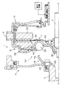
図1に本発明の第1実施形態としてのクラッチ装置1の縦断面概略図を示す。クラッチ装置1は、エンジンのクランクシャフト2からトランスミッションの入力シャフト3にトルクを伝達及び遮断するための装置である。図1の左側にエンジン(図示せず)が配置され、図1の右側にトランスミッション(図示せず)が配置されている。
【0046】
クラッチ装置1は、主に、質量体5と、クラッチディスク組立体7と、クラッチカバー組立体8(フライホイール)と、レリーズ機構10とを備えている。なお、クラッチカバー組立体8はフライホイールの一例である。また、クラッチカバー組立体8のクラッチカバー28以外の部分はフライホイール本体の一例である。
【0047】
質量体5はクランクシャフト2の先端に固定されている。質量体5はクランクシャフト2側に大きな慣性モーメントを確保するための部材である。質量体5は円板状部材12と環状部材13とから構成されている。円板状部材12は内周端が複数のボルト15によってクランクシャフト2の先端に固定されている。ボルト15は軸方向トランスミッション側から取り付けられている。円板状部材12の内周縁は、クランクシャフト2の先端面に形成された環状突出部2aの外周面に当接している。環状部材13は円板状部材12の外周端軸方向トランスミッション側に固定されている。環状部材13は軸方向厚みの大きいイナーシャ部材である。環状部材13は円周方向に並んだ複数のボルト16によって円板状部材12に固定されている。ボルト16は軸方向エンジン側から取り付けられている。さらに、円板状部材12の外周縁にはエンジン始動用リングギア17が固定されている。なお、質量体は一体の部材から構成されていてもよい。
【0048】
摩擦駆動板23は質量体5の軸方向トランスミッション側に間隔をあけて配置された円板状かつ環状の部材である。摩擦駆動板23の外径は環状部材13の外径とほぼ等しい。但し、摩擦駆動板23の内径は環状部材13の内径より小さくかつ円板状部材12の内径より大きい。摩擦駆動板23は軸方向エンジン側に環状かつ平坦な摩擦面25を有している。さらに、摩擦駆動板23の摩擦面25より外周側の部分には、円周方向に並んで複数の軸方向貫通孔26が形成されている。
【0049】
クラッチディスク組立体7は、クラッチディスク82と、連結プレート83と、ハブ85とから主に構成されている。クラッチディスク82はプレートとそのプレートの両面に設けられた1対の摩擦フェーシングとから構成されている。クラッチディスク82は摩擦駆動板23の摩擦面25に近接して配置されている。連結プレート83は環状かつ円板状のプレート部材であり、後述するクラッチカバー28の内周側部分33の軸方向トランスミッション側に近接して配置されている。連結プレート83の外周部は図示しないリベット等によりクラッチディスク82のプレートに固定されている。また、連結プレート83の内周部複数のリベット84によってハブ85のフランジに固定されている。ハブ85の内周面には入力シャフト3と係合するスプライン孔が形成されている。
【0050】
次に、クラッチカバー組立体8について説明する。クラッチカバー組立体8は、摩擦駆動板23に対して軸方向エンジン側に取り付けられた主にクラッチカバー28の外周側部分32と、プレッシャープレート51と、コーンスプリング52とから構成されている。
【0051】
クラッチカバー28(プレート部材)は、質量体5の軸方向トランスミッション側に近接して配置された円板状かつ環状のプレート部材である。クラッチカバー28の外径は環状部材13の外径とほぼ等しいが、内径は円板状部材12の内径よりさらに小さい。クラッチカバー28はその半径方向中間で外周側部分32と内周側部分33とに分かれている。外周側部分32は概ね軸方向エンジン側に突出するように曲げられており、摩擦駆動板23との軸方向間に空間を確保している。また、内周側部分33は軸方向トランスミッション側に突出するように曲げられており、円板状部材12との軸方向間に空間を確保している。外周側部分32の最外周縁部分34は図示しないボルト等により摩擦駆動板23の外周部に固定されている。また、内周側部分33の内周端は筒状部37とその先端から内周側に延びるフランジ38とから構成されている。筒状部37の外周面はクランクシャフト2の環状突出部2aの内周面に当接し、フランジ38はクランクシャフト2において環状突出部2aより内周側の軸方向端面2bに軸方向トランスミッション側から当接している。このように、クラッチカバー28の内周端はクランクシャフト2に対して半径方向及び軸方向の位置決めがされている。さらに、筒状部37と入力シャフト3と間に軸受39が配置されている。軸受39はインナーレースとアウターレースと複数の転動体とからなるラジアル軸受であり、クラッチカバー28に対して入力シャフト3を回転自在に支持している。
【0052】
プレッシャープレート51はクラッチディスク82の軸方向エンジン側に配置された環状の部材である。プレッシャープレート51はクラッチディスク82に対向する環状かつ平坦な押圧面51aを有している。
【0053】
コーンスプリング52(付勢部材)は、外周側部分32とプレッシャープレート51との軸方向間に配置されている。コーンスプリング52の外周端はプレッシャープレート51の環状突出部51bに支持され、その内周端はクラッチカバー28に形成された環状突出部35に支持されている。この状態でコーンスプリング52は軸方向に弾性変形させられており、それによりプレッシャープレート51に対して軸方向トランスミッション側に付勢する力を与えている。また、コーンスプリング52の内周面はクラッチカバー28に形成された筒状部分の外周面に支持され、半径方向の位置決めがされている。付勢部材の種類はコーンスプリングに限定されない。
【0054】
ダンパー機構24はクラッチカバー組立体8をクランクシャフト2に対して回転方向に弾性的に連結するための機構である。ダンパー機構24は、ドライブ部材29と、クラッチカバー28の内周側部分33と、複数の弾性部材30とから構成されている。
【0055】
ドライブ部材29は、環状のプレート部材であり、前述の複数のボルト15によってクランクシャフト2の先端に固定されている。ドライブ部材29は、円板状部材12の内周端の軸方向トランスミッション側に当接する環状部分と、その外周縁から軸方向トランスミッション側に延びる複数の当接部46とを有している。
【0056】
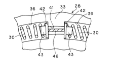
クラッチカバー28の内周側部分33には、円周方向に延びる複数のばね保持部36が形成されている。ばね保持部36は他の部分に比べて軸方向トランスミッション側に突出するように絞り加工で形成された突出部分であり、軸方向エンジン側に凹んでいる。各ばね保持部36の円周方向間にはばね保持部36に比べて半径方向が短い凹部41が形成されている。
【0057】
各弾性部材30は、円周方向に長く延びるコイルスプリングであり、ばね保持部36内に収容されている。弾性部材30の円周方向両端にはスプリングシート43が配置されており、スプリングシート43は各弾性部材30の円周方向両端を支持すると共に凹部41の半径方向両側に形成された支持面42に当接している。スプリングシート43は、弾性部材30を支持する支持部と、その支持部から弾性部材30のコイル内に延びる突出部とを有している。ここで、前述のドライブ部材29の当接部46は凹部41内に延びてその円周方向両端がスプリングシート43の支持部背面に当接又は近接している。このようにして、ドライブ部材29のトルクは弾性部材30を介してクラッチカバー28に伝達されるようになっている。さらに、ばね保持部36の外周側部分には、弧状又は環状の保持プレート48が複数のリベット49によって固定されている。保持プレート48は弾性部材30の半径方向外側においてその軸方向エンジン側を支持するようになっている。これにより、弾性部材30はクラッチカバー28に保持され、軸方向に脱落しないようになっている。また、ドライブ部材29の当接部46はこの保持された弾性部材30に対して軸方向からの移動のみによって係合又は係合解除することができる。なお、弾性部材の種類はコイルスプリングに限定されず、板状部材を折り曲げて複数のばね要素を形成した曲がり板ばねであってもよい。
【0058】
以上に述べたように、クラッチカバー28は、内周側部分33によってダンパー機構24の出力側部材を構成し、外周側部分32によってクラッチカバー組立体8のばね支持部を構成している。このように1つの部材に複数の機能を持たせることで全体の部品点数が少なくなっている。さらに、外周側部分32に形成された軸方向トランスミッション側を向く凹部内にプレッシャープレート51及びコーンスプリング52を収容し、さらに内周側部分33に形成された軸方向エンジン側を向く凹部内に弾性部材30、ドライブ部材29さらにはボルト15の頭部を収容しているため、半径方向及び軸方向にコンパクトな構造になっている。特に弾性部材30がプレッシャープレート51の内周側に配置されている構造が効果的である。ここで、例えばダンパー機構24の弾性部材30をプレッシャープレート51の軸方向エンジン側に配置すれば装置全体の軸方向寸法が大きくなり、又は弾性部材30をプレッシャープレート51の半径方向外側に配置すれば装置全体の半径方向寸法が大きくなってしまう。
【0059】
さらに、前述の環状部材13はクラッチカバー28の外周側部分32のさらに外周側に配置されており、クラッチ装置1の軸方向及び半径方向寸法を大きくすることなく十分な慣性モーメントを確保している。
【0060】
以上に述べたように、クラッチカバー組立体8はダンパー機構24を介して直接クランクシャフト2に連結されている。このため、ダンパー機構24の構造が簡単かつコンパクトにな、組み付け作業性が向上している。
【0061】
次にレリーズ機構10について説明する。レリーズ機構10は主にカバー組立体54と駆動機構55とから構成されている。カバー組立体54は摩擦駆動板23の軸方向トランスミッション側に取り付けられている。すなわちカバー組立体54は摩擦駆動板23に対してクラッチカバー組立体8と反対側に配置されている。カバー組立体54は、後述する駆動機構55からの荷重をプレッシャープレート51に伝えることでクラッチ連結を解除するための機構である。カバー組立体54は、カバー部材57と、レリーズ部材58と、レバー部材59とから構成されている。
【0062】
カバー部材57は環状のプレート部材であり、摩擦駆動板23の外周側面に当接する外周部57aと、外周部57aの内周縁から軸方向トランスミッション側に延びる筒状部57bと、筒状部57bの先端から内周側に延びる内周部57cとを有している。内周部57cは摩擦駆動板23の軸方向トランスミッション側面から軸方向に離れて配置されている。外周部57aは図示しないボルト等によって摩擦駆動板23の外周部に固定されている。内周側部57cには軸方向エンジン側に延びる環状突出部68が形成されている。
【0063】
レリーズ部材58は軸方向に延びる駆動部材60と支持部形成部材61とから構成されている。駆動部材60は、図2に示すように概ね筒状の部材であり、環状の着座部62と、着座部62から軸方向トランスミッション側に延びる複数の軸方向延長部63とから構成されている。着座部62の軸方向エンジン側端はプレッシャープレート51の軸方向トランスミッション側の外周縁に形成された溝51cに当接している。また、着座部62の先端側内周面は溝51cの外周面に当接して半径方向の位置決めがされている。このように環状の着座部62によって、駆動部材60のプレッシャープレート51に対する姿勢が安定している。軸方向延長部63は、図1及び図2に示すように、摩擦駆動板23の軸方向貫通孔26内を軸方向に貫通しており、先端は摩擦駆動板23の軸方向トランスミッション側面よりさらに突出している。軸方向延長部63の先端は、半径方向内側に折り曲げられてさらに軸方向に延びる折り曲げ部64となっている。
【0064】
支持部形成部材61は、駆動部材60に環状の支持部を形成するための部材であり、駆動部材60に対して軸方向トランスミッション側から容易に着脱可能である。支持部形成部材61は、概ね環状のプレート部材であり、円板状部93とその外周端から軸方向トランスミッション側に延びる筒状部94とから構成されている。円板状部93には軸方向トランスミッション側に突出する環状突出部67が形成されている。環状突出部67は環状突出部の外周側に配置している。筒状部94の先端は折り曲げ部64の外周側に当接している。また、筒状部94には切り曲げられて折り曲げ部64の内周側に当接する屈曲部66とを有している。屈曲部66は折り曲げ部64の円周方向中間に位置している。このようにして、筒状部94と屈曲部66との半径方向間に折り曲げ部64が挟まれており、支持部形成部材61は各軸方向延長部63の先端に対して軸方向及び半径方向に移動不能に係合している。
【0065】
レバー部材59は環状かつ円板状のプレート部材である。レバー部材59の外周部はカバー部材57の内周側部57cの軸方向エンジン側に近接して配置されている。レバー部材59の外周端は支持部形成部材61の環状突出部67に軸方向トランスミッション側から当接し、さらにその内周側の部分はカバー部材57の環状突出部68に軸方向エンジン側から当接している。レバー部材59は例えば円板状プレートに内周縁及び外周縁から交互に形成されたスリットによって弾性機能をほとんど有さず単にレバーとしてのみ機能するようになっていてもよい。以上に述べた構造において、レバー部材59の内周端が軸方向トランスミッション側に移動すると、カバー部材57の環状突出部68を支点としてレバー部材59の外周端が軸方向エンジン側に回動し、レリーズ部材58を軸方向エンジン側に移動させる。これにより、プレッシャープレート51はコーンスプリング52からの付勢力に打ち勝ってクラッチディスク82から離れていく。
【0066】
駆動機構55はレバー部材59を駆動することでクラッチレリーズ動作を行うための機構である。駆動機構55は主にレリーズベアリング69と油圧シリンダ70と油圧回路71とから構成されている。レリーズベアリング69は主にインナーレースとアウターレースとその間に配置された複数の転動体からなり、ラジアル荷重及びスラスト荷重を受けることが可能となっている。レリーズベアリング69のアウターレースには、筒状部材72が装着されている。筒状部材72はアウターレースの外周面に当接する筒状部73と、筒状部73の軸方向エンジン側端から半径方向外側に延びる第1フランジ74と、筒状部73の軸方向トランスミッション側端から半径方向内側に延びアウターレースの軸方向トランスミッション側面に当接する第2フランジ75とを有している。第1フランジ74はレバー部材59の半径方向内側端に軸方向エンジン側から当接している。
【0067】
油圧シリンダ70は、油圧室構成部材76と、ピストン77とから主に構成されている。油圧室構成部材76はその内周側に配置されたピストン77との間に油圧室79を構成している。油圧室79内には油圧回路71から油圧が供給可能となっている。ピストン77は筒状の部材であり、その内周面はトランスミッション側から延びる筒状シャフト80の外周面に支持されている。さらに、ピストン77はレリーズベアリング69のインナーレースに対して軸方向エンジン側から当接するフランジ78を有している。この状態で油圧回路71から油圧室79内に油圧が供給されると、ピストン77は軸方向トランスミッション側に移動しレリーズベアリング69を移動させる。
【0068】
次に、クラッチ装置1の組み付け動作について説明する。図4に示すように、エンジン側の構成としては、ボルト15によってクランクシャフト2の先端に質量体5とドライブ部材29とが予め固定されている。また、クラッチカバー28には、弾性部材30が予め取り付けられている。これは組み付け動作前にダンパー機構24を主に構成する弾性部材30があらかじめクラッチカバー組立体8の一部すなわちクラッチカバー28に装着されていることを意味する。このため、組付け前のクラッチカバー組立体8及び弾性部材30の運搬や保管が便利になっている。
【0069】
この状態から例えばエンジン及びクランクシャフトを軸方向トランスミッション側に移動させて行く。すると、ドライブ部材29の当接部46は軸方向トランスミッション側から各弾性部材30の円周方向間に、より具体的にはスプリングシート43の間に挿入される。クランクシャフト2の軸方向端面2bがクラッチカバー28のフランジ38に当接すると、両者の軸方向相対移動が停止する。以上に述べたように、クランクシャフト2とクラッチカバー組立体8との組み付け動作は、両側の部材を軸方向に移動させるだけで完了し、ボルトやリベット等の締結部材等を必要としない。このようにクラッチ装置1の組み付け時の作業が簡単になり、組み付け作業が短時間で行える。一言で言うと、クラッチ装置1の組み付け性が向上している。
第2実施形態
図5及び図6に本発明の第2実施形態としてのクラッチ装置1の縦断面概略図を示す。このクラッチ装置1の基本的構造は前記実施形態と同様であるので、ここでは異なる点についてのみ説明する。
【0070】
筒状部材72の筒状部73には、軸方向トランスミッション側に延びる延長部87がさらに形成されている。これにより、筒状部材72には軸方向に長い外周面91が形成されている。
【0071】
カバー部材57の内周側部57cは、前記実施形態よりさらに内周側に延びており、内周側延長部88を形成している。これにより、内周側部57cの内径は、レバー部材59の内径とほぼ等しくなっており、レリーズベアリング69の近傍に位置している。内周側部57cに形成された内周側延長部88には複数の孔88aが形成されている。さらに、内周側延長部88の内周縁には軸方向エンジン側に延びる筒状部89が形成されている。この筒状部89の内周側には筒状部材90が固定されている。筒状部材90の内周面は延長部87の外周面91に支持されている。ここで、カバー部材57はクラッチカバー組立体8、摩擦駆動板23及びカバー組立体54からなる一体の構成において最もトランスミッション側に配置された部材であり、その部材がトランスミッション側の他の部材によって支持されていることになる。この結果、エンジンンからの曲げ振動によってクラッチ装置1全体が傾きにくくなっており、エンジンの曲げ振動によって発生する共振現象を抑えることができる。これにより、クラッチカバー28の板厚を小さくできる。
【0072】
また、クラッチカバー28はクラッチカバー組立体8、摩擦駆動板23及びカバー組立体54からなる一体の構成において最も軸方向エンジン側に配置された部材であり、その内周端がクランクシャフト2に支持されているため、結果として軸方向両側でそれぞれクラッチ装置1の支持が行われている。そのため、さらに、エンジン側からの曲げ振動に対して共振現象を生じにくなっている。
【0073】
また、カバー部材57の内周端を支持するための部材としてレリーズベアリング69を用いているため、特別な部品やそのためのスペースが不要である。別の表現を用いると、筒状部材72は、レバー部材59を駆動するための第1フランジ74と、カバー部材57を支持するための延長部87とを有している。さらに、内周側延長部88側に軸方向に長い筒状部材90を用いることで、カバー部材57の内周面と他の部材との軸方向接触長さを長くすることができ、カバー部材57がより傾きにくくなっている。さらに、筒状部材90に低摩擦係数の材料を用いるなどして、レリーズベアリング69が軸方向に移動する際に当接部分間での摺動抵抗を小さくできる。
第3実施形態
図7及び図8に本発明の第3実施形態としてのクラッチ装置の縦断面概略図を示す。本実施形態のクラッチ装置1は基本構造が第1実施形態のものと同様であるので、ここでは異なる点についてのみ説明する。
【0074】
カバー部材57’における環状突出部68’は、第1実施形態の環状突出部68に比べて外周側に位置している。また、支持部形成部材61’の環状突出部67’は第1実施形態の環状突出部67に比べて内周側に位置している。これにより、レバー部材59’の外周端は環状突出部68’に対して軸方向エンジン側から当接し、さらにその内周側部分は環状突出部67’に対して軸方向トランスミッション側から当接している。レリーズベアリング69’のアウターレースに設けられた筒状部材72’は、アウターレース外周面に当接する筒状部73’と、筒状部73’の軸方向エンジン側端から内周側に突出しアウターレースの軸方向エンジン側面に当接する第2フランジ75’と、筒状部73’の軸方向トランスミッション端から外周側に延びる第1フランジ74’とを有している。第1フランジ74’はレバー部材59’の内周端に軸方向トランスミッション側から当接している。
【0075】
クラッチカバー28は、軸方向に薄い板金製であり、軸方向に弾性変形可能である。さらに、クラッチカバー28の外周側部分32において平坦な環状部分32aの軸方向エンジン側には摩擦フェーシング99が接着されている。摩擦フェーシング99は円板状部材12の平坦な面に対して軸方向に対向している。図7に示すクラッチ連結状態では、摩擦フェーシング99と円板状部材12との軸方向間には隙間が確保されている。
【0076】
図7に示す状態から、油圧回路71によって油圧室79内の作動油がドレンされると、ピストン77は軸方向エンジン側に移動する。これにより、レリーズベアリング69’はレバー部材59’の内周端を軸方向エンジン側に移動させる。レバー部材59’はカバー部材57’の環状突出部68’を支点として回動し、レリーズ部材58を軸方向エンジン側に移動させる。これによりプレッシャープレート51はコーンスプリング52の付勢力に打ち勝ってクラッチディスク82から離れる。このとき、レリーズベアリング69’からクラッチカバー組立体8に対して軸方向エンジン側に作用する荷重によって、クラッチカバー28の特に外周側部分32が軸方向エンジン側に弾性変形する。これより、摩擦フェーシング99が円板状部材12に当接して摩擦係合する。すなわち、ダンパー機構24の出力側部材であるクラッチカバー28がクランクシャフト2と一体回転する円板状部材12と摩擦係合して一体回転するようになる。さらに言い換えると、クラッチカバー28や摩擦駆動板23がクランクシャフト2に対してロックされた状態となり、ダンパー機構24が作動しない。したがって、エンジン始動時の低回転数領域(例えば回転数0〜500rpm)での共振点通過時には、クラッチをレリーズすることで、共振によるダンパー機構24の破損や音/振動を生じにくくしている。
【0077】
以上に述べた構造及び動作をまとめて説明すると、このクラッチ装置1では、レリーズ機構10がクラッチカバー組立体8に対して荷重を付与することでクラッチをレリーズすると、その荷重を利用してクラッチカバー28の摩擦フェーシング99が円板状部材12に摩擦係合させられる。ここでは、ダンパー機構24のロックがクラッチレリーズ時におけるレリーズ機構10からの荷重を利用しているため、構造が簡単になる。特に、ロック機構が円板状部材12やクラッチカバー28といった従来部材からなるため、特別な構造を設ける必要がない。
【0078】
ここで本実施形態と第1実施形態とを比べてみると、本実施形態のクラッチ装置はレバー部材59’の内周端を軸方向エンジン側に押すことでクラッチをレリーズするプッシュタイプであり、第1実施形態のクラッチ装置はレバー部材59の内周端を軸方向トランスミッション側に引くことでクラッチをレリーズするプルタイプである。ここで両者の違いはカバー組立体54や駆動機構55などのレリーズ機構10のみに存在し、クラッチカバー組立体8のプレッシャープレート51やコーンスプリング52は共通していることが分かる。言い換えると、共通部分に対してカバー部材、支持部形成部材等を変えるだけでプルタイプのクラッチ装置とプッシュタイプのクラッチ装置とを製造できる。ここで、レリーズ部材58において駆動部材60は共通部品であり交換する必要がないため、異なる部材はすべて軸方向トランスミッション側から取付可能であり、作業性がよい。
第4実施形態
図9及び図10に本発明の第4実施形態としてのクラッチ装置1の縦断面概略図を示す。この実施形態のクラッチ装置1は前記第3実施形態と基本構造が同様であるため、異なる点についてのみ詳細に説明する。
【0079】
筒状部材72’の筒状部73’には、軸方向トランスミッション側に延びる延長部87’がさらに形成されている。これにより、筒状部材72’には軸方向に長い外周面91’が形成されている。
【0080】
カバー部材57’の内周側部57c’は、前記実施形態よりさらに内周側に延びており、内周側延長部88’を形成している。これにより、内周側部57c’の内径はレバー部材59’の内径とほぼ等しくなっており、レリーズベアリング69の近傍に位置している。内周側延長部88’には複数の孔88a’が形成されている。さらに、内周側延長部88’の内周縁には軸方向トランスミッション側に延びる筒状部89’が形成されている。この筒状部89’の内周側には筒状部材90’が固定されている。筒状部材90’の内周面は延長部87’の外周面91’に支持されている。ここで、カバー部材57’はクラッチカバー組立体8、摩擦駆動板23及びカバー組立体54からなる一体の構成において最もトランスミッション側に配置された部材であり、その部材がトランスミッション側の他の部材によって支持されていることになる。この結果、エンジンンからの曲げ振動によってクラッチ装置1全体が傾きにくくなっており、エンジンの曲げ振動によって発生する共振現象を抑えることができる。これにより、クラッチカバー28の板厚を小さくできる。
【0081】
また、クラッチカバー28はクラッチカバー組立体8、摩擦駆動板23及びカバー組立体54からなる一体の構成において最も軸方向エンジン側に配置された部材であり、その内周端がクランクシャフト2に支持されているため、結果として軸方向両側でそれぞれクラッチ装置1の支持が行われている。そのため、さらに、エンジン側からの曲げ振動に対して共振現象を生じにくくなっている。
【0082】
また、カバー部材57’の内周端を支持するための部材としてレリーズベアリング69を用いているため、特別な部品やそのためのスペースが不要である。別の表現を用いると、筒状部材72’は、レバー部材59’を駆動するための第1フランジ74’とカバー部材57’を支持するための延長部87’とを有している。さらに、内周側延長部88側に軸方向に長い筒状部材90’を用いることで、カバー部材57’の内周面と他の部材との軸方向接触長さを長くすることができ、カバー部材57’がより傾きにくくなっている。さらに、筒状部材90’に低摩擦係数の材料を用いるなどして、レリーズベアリング69が軸方向に移動する際に当接部分間での摺動抵抗を小さくできる。
〔変形例〕
本発明は前記実施形態に限定されない。本発明は、他の種類のクラッチ装置、例えば、クラッチカバー組立体が摩擦板の軸方向トランスミッション側に配置されたクラッチ装置や、摩擦駆動板の軸方向両側に別のクラッチカバー組立体を設け2出力を可能とするクラッチ装置にも採用できる。
【0083】
【発明の効果】
本発明に係るクラッチ装置では、ダンパー機構はクランクシャフトとフライホイールとを互いに軸方向に接近させることで組み付けることができる。すなわち、従来に比べて組み付け性が向上している。
【図面の簡単な説明】
【図1】 本発明の第1実施形態としてのクラッチ装置の縦断面概略図。
【図2】 レリーズ部材を説明するための部分側面図。
【図3】 ダンパー機構を説明するための部分平面図。
【図4】 フライホイールの組み付け動作を説明するための縦断面概略図。
【図5】 本発明の第2実施形態としてのクラッチ装置の縦断面概略図。
【図6】 フライホイールの組み付け動作を説明するための縦断面概略図。
【図7】 本発明の第3実施形態としてのクラッチ装置の縦断面概略図。
【図8】 フライホイールの組み付け動作を説明するための縦断面概略図。
【図9】 本発明の第4実施形態としてのクラッチ装置の縦断面概略図。
【図10】 フライホイールの組み付け動作を説明するための縦断面概略図。
【符号の説明】
1 クラッチ装置
2 クランクシャフト
3 入力シャフト
5 質量体
7 クラッチディスク組立体
8 クラッチカバー組立体
10 レリーズ機構
23 摩擦駆動板
28 クラッチカバー
29 ドライブ部材
30 弾性部材
51 プレッシャープレート
52 コーンスプリング[0001]
BACKGROUND OF THE INVENTION
The present invention relates to a clutch device, and more particularly to a clutch device attached to a crankshaft via an elastic member.
[0002]
[Prior art]
The clutch device is a device for transmitting the power from the engine to the input shaft of the transmission and interrupting the power as necessary. The clutch device mainly includes a friction drive plate to which power is input from a transmission crankshaft, a clutch disk disposed in the vicinity of the friction drive plate, and urges the clutch disk to the friction drive plate as needed. And a clutch cover assembly for releasing the bias of the lever. The clutch cover assembly includes a clutch cover provided to rotate integrally with the friction drive plate, a pressure plate disposed in the clutch cover and disposed close to the clutch disk, and supported by the clutch cover to clutch the pressure plate. And an urging member for urging the disc and the friction drive plate.
[0003]
A damper mechanism for absorbing and attenuating torque fluctuations from the engine is disposed, for example, between the friction drive plate and the engine-side member. The damper mechanism generally includes an input side member fixed to the engine side member, an output side member fixed to the clutch cover assembly side, and an elastic member for elastically connecting the two members in the rotational direction. is doing.
[0004]
[Problems to be solved by the invention]
When the conventional clutch device is assembled, the damper mechanism is previously attached to one of the clutch device and the engine side member. When the engine is assembled to the transmission in this state, the damper mechanism is fixed to the other of the clutch device and the engine-side member with bolts or rivets.
[0005]
Thus, since it is necessary to use fastening members, such as a volt | bolt and a rivet, at the time of the assembly | attachment of a clutch apparatus, the assembly workability | operativity falls.
[0006]
An object of the present invention is to improve the assembly of the clutch device.
[0007]
[Means for Solving the Problems]
The clutch device according to claim 1 is a device for transmitting / cutting off the power from the crankshaft of the engine to the input shaft of the transmission by connecting / disconnecting the clutch disk. The clutch device includes a clutch cover assembly for connecting and releasing the clutch disk, and a damper mechanism for elastically connecting the clutch cover assembly to the crankshaft in the rotational direction. A part of the damper mechanism is disposed between the crankshaft and the input shaft in the radial direction, is rotatably supported by the crankshaft, and supports the input shaft in the radial direction.
[0008]
In this clutch device, the structure is simplified because the clutch cover is connected to the crankshaft via a damper mechanism.
[0009]
According to a second aspect of the present invention, in the clutch device according to the first aspect, the damper mechanism includes an elastic member that is held by one of the crankshaft and the clutch cover assembly and is detachably engaged with the other in the axial direction. Have.
[0010]
In this clutch device, the damper mechanism can be assembled by causing the crankshaft and the flywheel to approach each other in the axial direction. That is, the assembling property is improved as compared with the conventional case.
[0011]
According to a third aspect of the present invention, in the clutch device according to the second aspect, the damper mechanism includes a disk-shaped plate member disposed on the axial engine side at the tip of the crankshaft, both circumferential ends and the axial transmission by the plate member. And a drive member fixed to the crankshaft having contact portions that are detachable from the axial direction at both ends in the circumferential direction of the elastic member.
[0012]
In this clutch device, the elastic member is held in advance by the plate member, and when assembled, the contact portion of the drive member is engaged with both ends in the circumferential direction of the elastic member from the axial direction. Thus, the assembling property is improved.
[0013]
According to a fourth aspect of the present invention, in the clutch device according to the third aspect, the plate member has a holding portion for holding the elastic member in the axial direction engine side.
[0014]
In this clutch device, the elastic member cannot be detached from the plate member by the holding portion.
[0015]
According to a fifth aspect of the present invention, the clutch device according to any one of the first to fourth aspects further includes a friction drive plate disposed on the axial transmission side of the clutch disk. The plate member is disposed on the engine side of the clutch disk in the axial direction and is fixed to the friction drive plate.
[0016]
According to a sixth aspect of the present invention, in the clutch device according to the fifth aspect, the clutch cover assembly includes a pressure plate disposed on the axial engine side of the clutch disk, and a plate member that urges the pressure plate toward the clutch disk. It has an urging member to do.
[0017]
In this clutch device, since the plate member has a role of holding the elastic member and a role of supporting the urging member, the total number of parts is reduced.
[0018]
In the clutch device according to a seventh aspect, in the sixth aspect, the elastic member is disposed on the inner peripheral side of the pressure plate.
[0019]
In this clutch device, since the elastic member is disposed on the inner peripheral side of the pressure plate, the radial dimension can be reduced while suppressing the overall axial dimension.
[0020]
In the clutch device according to an eighth aspect, in any one of the fifth to seventh aspects, the plate member has an outer peripheral end fixed to the friction drive plate and an inner peripheral end rotatably supported by the crankshaft.
[0021]
According to a ninth aspect of the present invention, the clutch device according to the eighth aspect further includes a bearing disposed between the inner peripheral end of the plate member and the input shaft.
[0022]
In this clutch device, the input shaft is supported on the inner peripheral end of the plate member via a bearing.
[0023]
The clutch device according to
[0024]
In the clutch device according to an eleventh aspect, in the tenth aspect, the elastic member is located on the inner peripheral side of the pressure plate.
[0025]
In this clutch device, since the elastic member is disposed on the inner peripheral side of the pressure plate, the radial dimension can be reduced while suppressing the overall axial dimension.
[0026]
According to a twelfth aspect of the present invention, the clutch device according to any one of the first to eleventh aspects further includes a mass body fixed to the crankshaft.
[0027]
In this clutch device, the mass body is directly fixed to the crankshaft, and is not engaged with the flywheel assembly or the damper mechanism. For this reason, the structure is simplified and the overall dimensions can be reduced.
[0028]
In the clutch device according to a thirteenth aspect, in the twelfth aspect, the mass body includes a disk-shaped member whose inner peripheral end is fixed to the crankshaft, and an annular member fixed to the outer peripheral end of the disk-shaped member. Have. In this clutch device, since the annular member is fixed to the outer peripheral end of the disk-shaped member, the axial dimension of the entire device can be shortened while maintaining a sufficient inertia.
[0029]
According to a fourteenth aspect of the present invention, there is provided a flywheel assembly for transmitting and blocking power from an engine crankshaft to an input shaft of a transmission, and includes a flywheel and a damper mechanism. The damper mechanism is a mechanism for elastically connecting the flywheel to the crankshaft in the rotational direction, and includes a drive member directly fixed to the crankshaft and an elastic member driven by the drive member . A part of the flywheel is disposed between the crankshaft and the input shaft in the radial direction, is rotatably supported by the crankshaft, and supports the input shaft in the radial direction.
[0030]
The flywheel assembly has a simple structure because the drive member of the damper mechanism is directly fixed to the crankshaft.
[0031]
According to a fifteenth aspect of the present invention, the flywheel assembly according to the fourteenth aspect further includes a mass body that is fixed to the crankshaft and is separate from the drive member .
[0032]
This flywheel assembly has a simple structure because the drive member of the damper mechanism is fixed to the crankshaft without passing through the mass body.
[0033]
A flywheel assembly according to a sixteenth aspect of the present invention is the flywheel assembly according to the fifteenth aspect, further comprising a bolt for fixing the drive member and the mass body to the crankshaft.
[0034]
The flywheel assembly according to
[0035]
The flywheel assembly according to claim 18 is for transmitting / blocking power from an engine crankshaft to an input shaft of a transmission, and includes a flywheel body , a plate member, and a damper mechanism. ing. The plate member is fixed to the flywheel body . The damper mechanism is a mechanism for elastically connecting the flywheel body to the crankshaft in the rotational direction, and has an elastic member that is held on the plate member so as not to fall off. The inner peripheral portion of the plate member is disposed between the crankshaft and the input shaft in the radial direction, is rotatably supported by the crankshaft, and supports the input shaft in the radial direction.
[0036]
In this flywheel assembly, since the elastic member of the damper mechanism is held on the plate member so as not to fall off, the flywheel assembly can be easily managed and transported.
[0037]
According to a nineteenth aspect of the present invention, in the flywheel assembly according to the eighteenth aspect, the plate member has an elastic member holding portion opened on the crankshaft side.
[0038]
In this flywheel assembly, the elastic member is accessible from the crankshaft side.
[0039]
A flywheel assembly according to claim 20 is the drive member according to claim 18 or 19, which is fixed to the crankshaft and is detachably engaged in the axial direction with respect to the rotational direction end of the elastic member of the damper mechanism. Is further provided.
[0040]
In this flywheel assembly, since the drive member is detachable in the axial direction with respect to the elastic member, the flywheel assembly, the plate member, and the damper mechanism are assembled only by moving in the axial direction with respect to the drive member. be able to.
[0041]
The flywheel assembly according to claim 21 is the flywheel assembly according to claims 18 to 20, wherein the drive member is a plate.
[0042]
This flywheel assembly has a simple structure because the drive member is a plate.
[0043]
In a flywheel assembly according to a twenty-second aspect, in the twentieth or twenty-first aspect, the drive member has a plurality of abutting portions that extend in the axial direction and engage with rotation direction ends of the elastic member.
[0044]
A flywheel assembly according to a twenty-third aspect of the present invention is the flywheel assembly according to any one of the twenty-second to twenty-second aspects, further including a mass body that is fixed to the crankshaft and separate from the drive member.
[0045]
DETAILED DESCRIPTION OF THE INVENTION
First Embodiment FIG. 1 is a schematic longitudinal sectional view of a clutch device 1 as a first embodiment of the present invention. The clutch device 1 is a device for transmitting and interrupting torque from the
[0046]
The clutch device 1 mainly includes a mass body 5, a
[0047]
The mass body 5 is fixed to the tip of the
[0048]
The
[0049]
The
[0050]
Next, the
[0051]
The clutch cover 28 (plate member) is a disk-like and annular plate member that is disposed close to the mass body 5 on the axial transmission side. The outer diameter of the
[0052]
The
[0053]
The cone spring 52 (biasing member) is disposed between the outer
[0054]
The
[0055]
The
[0056]
A plurality of
[0057]
Each
[0058]
As described above, the
[0059]
Further, the above-described
[0060]
As described above, the
[0061]
Next, the
[0062]
The
[0063]
The
[0064]
The support portion forming member 61 is a member for forming an annular support portion on the
[0065]
The
[0066]
The
[0067]
The
[0068]
Next, the assembly operation of the clutch device 1 will be described. As shown in FIG. 4, as a configuration on the engine side, the mass body 5 and the
[0069]
From this state, for example, the engine and the crankshaft are moved to the axial transmission side. Then, the
Second Embodiment FIGS. 5 and 6 show schematic longitudinal sectional views of a clutch device 1 according to a second embodiment of the present invention. Since the basic structure of the clutch device 1 is the same as that of the above embodiment, only different points will be described here.
[0070]
The
[0071]
The inner
[0072]
The
[0073]
Further, since the release bearing 69 is used as a member for supporting the inner peripheral end of the
Third Embodiment FIGS. 7 and 8 show schematic longitudinal sectional views of a clutch device according to a third embodiment of the present invention. Since the basic structure of the clutch device 1 of this embodiment is the same as that of the first embodiment, only different points will be described here.
[0074]
The
[0075]
The
[0076]
When the hydraulic fluid in the
[0077]
The structure and operation described above will be described together. In the clutch device 1, when the
[0078]
Here, comparing this embodiment with the first embodiment, the clutch device of this embodiment is a push type that releases the clutch by pushing the inner peripheral end of the
Fourth Embodiment FIGS. 9 and 10 are schematic longitudinal sectional views of a clutch device 1 as a fourth embodiment of the present invention. Since the basic structure of the clutch device 1 of this embodiment is the same as that of the third embodiment, only different points will be described in detail.
[0079]
The
[0080]
An inner
[0081]
The
[0082]
Further, since the release bearing 69 is used as a member for supporting the inner peripheral end of the
[Modification]
The present invention is not limited to the embodiment. The present invention provides another type of clutch device, for example, a clutch device in which the clutch cover assembly is disposed on the axial transmission side of the friction plate, or another clutch cover assembly provided on both axial sides of the friction drive plate. It can also be used in clutch devices that enable output.
[0083]
【The invention's effect】
In the clutch device according to the present invention, the damper mechanism can be assembled by causing the crankshaft and the flywheel to approach each other in the axial direction. That is, the assembling property is improved as compared with the conventional case.
[Brief description of the drawings]
FIG. 1 is a schematic longitudinal sectional view of a clutch device according to a first embodiment of the present invention.
FIG. 2 is a partial side view for explaining a release member.
FIG. 3 is a partial plan view for explaining a damper mechanism.
FIG. 4 is a schematic vertical cross-sectional view for explaining a flywheel assembling operation.
FIG. 5 is a schematic longitudinal sectional view of a clutch device according to a second embodiment of the present invention.
FIG. 6 is a schematic longitudinal sectional view for explaining the flywheel assembling operation.
FIG. 7 is a schematic longitudinal sectional view of a clutch device according to a third embodiment of the present invention.
FIG. 8 is a schematic vertical sectional view for explaining the flywheel assembling operation.
FIG. 9 is a schematic longitudinal sectional view of a clutch device according to a fourth embodiment of the present invention.
FIG. 10 is a schematic longitudinal sectional view for explaining the flywheel assembling operation.
[Explanation of symbols]
DESCRIPTION OF SYMBOLS 1
Claims (23)
前記クラッチディスクを連結・解除するためのクラッチカバー組立体と、
前記クラッチカバー組立体を前記クランクシャフトに回転方向に弾性的に連結するためのダンパー機構と、を備え、
前記ダンパー機構の一部は、前記クランクシャフトと前記入力シャフトとの半径方向間に配置されており、前記クランクシャフトに回転自在に支持されるとともに、前記入力シャフトを半径方向に支持している、
クラッチ装置。A clutch device for transmitting / cutting power from an engine crankshaft to an input shaft of a transmission by connecting / disconnecting a clutch disc,
A clutch cover assembly for connecting and releasing the clutch disk;
A damper mechanism for elastically connecting the clutch cover assembly to the crankshaft in a rotational direction,
A part of the damper mechanism is disposed between the crankshaft and the input shaft in the radial direction, is rotatably supported by the crankshaft, and supports the input shaft in the radial direction.
Clutch device.
前記プレート部材は前記クラッチディスクの軸方向エンジン側に配置され前記摩擦駆動板に固定されている、請求項1〜4のいずれかに記載のクラッチ装置。A friction drive plate disposed on the axial transmission side of the clutch disc;
The clutch device according to any one of claims 1 to 4, wherein the plate member is disposed on an axial engine side of the clutch disk and is fixed to the friction drive plate.
前記クラッチディスクの軸方向トランスミッション側に配置された摩擦駆動板と、
前記摩擦駆動板の軸方向エンジン側に固定されたクラッチカバーと、
前記クラッチディスクの軸方向エンジン側に近接して配置されたプレッシャープレートと、前記クラッチカバーに支持され前記プレッシャープレートを前記摩擦駆動板側に付勢するための付勢部材と、前記クラッチカバーの軸方向エンジン側に保持され前記クランクシャフトから動力が入力される弾性部材とを有するクラッチカバー組立体と、備え、
前記クラッチカバーの内周部は、前記クランクシャフトと前記入力シャフトとの半径方向間に配置されており、前記クランクシャフトに回転自在に支持されるとともに、前記入力シャフトを半径方向に支持している、
クラッチ装置。A clutch device for transmitting / cutting power from an engine crankshaft to an input shaft of a transmission by connecting / disconnecting a clutch disc,
A friction drive plate disposed on the axial transmission side of the clutch disk;
A clutch cover fixed to the axial engine side of the friction drive plate;
A pressure plate disposed close to the engine side of the clutch disk in the axial direction; a biasing member supported by the clutch cover for biasing the pressure plate toward the friction drive plate; and a shaft of the clutch cover A clutch cover assembly having an elastic member that is held on the direction engine side and receives power from the crankshaft,
An inner peripheral portion of the clutch cover is disposed between the crankshaft and the input shaft in the radial direction, is rotatably supported by the crankshaft, and supports the input shaft in the radial direction. ,
Clutch device.
フライホイールと、
前記フライホイールを前記クランクシャフトに回転方向に弾性的に連結するための機構であり、前記クランクシャフトに直接固定されたドライブ部材と、前記ドライブ部材によって駆動される弾性部材とを有するダンパー機構と、を備え、
前記フライホイールの一部は、前記クランクシャフトと前記入力シャフトとの半径方向間に配置されており、前記クランクシャフトに回転自在に支持されるとともに、前記入力シャフトを半径方向に支持している、
フライホイール組立体。A flywheel assembly for transmitting / blocking power from an engine crankshaft to an input shaft of a transmission,
With flywheel,
A damper mechanism for elastically connecting the flywheel to the crankshaft in a rotational direction, and a damper mechanism having a drive member directly fixed to the crankshaft and an elastic member driven by the drive member ; With
A part of the flywheel is disposed between the crankshaft and the input shaft in the radial direction, is rotatably supported by the crankshaft, and supports the input shaft in the radial direction.
Flywheel assembly.
フライホイール本体と、
前記フライホイール本体に固定されたプレート部材と、
前記フライホイール本体を前記クランクシャフトに回転方向に弾性的に連結するための機構であり、前記プレート部材に脱落不能に保持された弾性部材を有するダンパー機構と、を備え、
前記プレート部材の内周部は、前記クランクシャフトと前記入力シャフトとの半径方向間に配置されており、前記クランクシャフトに回転自在に支持されるとともに、前記入力シャフトを半径方向に支持している、
フライホイール組立体。A flywheel assembly for transmitting / blocking power from an engine crankshaft to an input shaft of a transmission,
The flywheel body ,
A plate member fixed to the flywheel body ;
A mechanism for elastically connecting the flywheel main body to the crankshaft in a rotational direction, and a damper mechanism having an elastic member that is held on the plate member so as not to fall off,
An inner peripheral portion of the plate member is disposed between the crankshaft and the input shaft in the radial direction, is rotatably supported by the crankshaft, and supports the input shaft in the radial direction. ,
Flywheel assembly.
Priority Applications (3)
| Application Number | Priority Date | Filing Date | Title |
|---|---|---|---|
| JP32460999A JP3961731B2 (en) | 1999-11-15 | 1999-11-15 | Clutch device |
| US09/695,082 US6481552B1 (en) | 1999-11-15 | 2000-10-25 | Clutch apparatus |
| DE10056733A DE10056733B4 (en) | 1999-11-15 | 2000-11-15 | coupling device |
Applications Claiming Priority (1)
| Application Number | Priority Date | Filing Date | Title |
|---|---|---|---|
| JP32460999A JP3961731B2 (en) | 1999-11-15 | 1999-11-15 | Clutch device |
Publications (2)
| Publication Number | Publication Date |
|---|---|
| JP2001140927A JP2001140927A (en) | 2001-05-22 |
| JP3961731B2 true JP3961731B2 (en) | 2007-08-22 |
Family
ID=18167739
Family Applications (1)
| Application Number | Title | Priority Date | Filing Date |
|---|---|---|---|
| JP32460999A Expired - Fee Related JP3961731B2 (en) | 1999-11-15 | 1999-11-15 | Clutch device |
Country Status (1)
| Country | Link |
|---|---|
| JP (1) | JP3961731B2 (en) |
Families Citing this family (1)
| Publication number | Priority date | Publication date | Assignee | Title |
|---|---|---|---|---|
| KR101542944B1 (en) | 2013-12-18 | 2015-08-12 | 씨스톤 테크놀로지스(주) | Dual mass torsion flywheel |
-
1999
- 1999-11-15 JP JP32460999A patent/JP3961731B2/en not_active Expired - Fee Related
Also Published As
| Publication number | Publication date |
|---|---|
| JP2001140927A (en) | 2001-05-22 |
Similar Documents
| Publication | Publication Date | Title |
|---|---|---|
| JP2009115262A (en) | Flywheel | |
| JP4054712B2 (en) | Clutch device | |
| JP3907372B2 (en) | Clutch device | |
| JP3961731B2 (en) | Clutch device | |
| JP2006162054A (en) | Damper disc assembly | |
| JP3940246B2 (en) | Clutch device | |
| JP2006162054A5 (en) | ||
| US6481552B1 (en) | Clutch apparatus | |
| JP3907371B2 (en) | Clutch device | |
| JP4022358B2 (en) | Clutch device | |
| JP3612156B2 (en) | Torque converter lockup damper and damper mechanism | |
| US20040206201A1 (en) | Flywheel assembly | |
| KR100582645B1 (en) | Flywheel assembly | |
| JP4434660B2 (en) | 2 mass flywheel | |
| JP4028947B2 (en) | Clutch device | |
| JP4110031B2 (en) | Flywheel assembly | |
| JPH10213204A (en) | Rock-up damper for torque converter | |
| JPH11325113A (en) | Clutch cover assembly | |
| JP3905056B2 (en) | Flywheel assembly | |
| JPS60260765A (en) | Fluid coupling having direct coupled clutch with vibration absorbing damper device | |
| JP2005061488A5 (en) | ||
| JP3977211B2 (en) | Clutch device | |
| JP4054504B2 (en) | Clutch device | |
| JP4045179B2 (en) | Flywheel assembly | |
| JP3977210B2 (en) | Flywheel assembly |
Legal Events
| Date | Code | Title | Description |
|---|---|---|---|
| A977 | Report on retrieval |
Free format text: JAPANESE INTERMEDIATE CODE: A971007 Effective date: 20051228 |
|
| A131 | Notification of reasons for refusal |
Free format text: JAPANESE INTERMEDIATE CODE: A131 Effective date: 20060613 |
|
| A521 | Written amendment |
Free format text: JAPANESE INTERMEDIATE CODE: A523 Effective date: 20060807 |
|
| A131 | Notification of reasons for refusal |
Free format text: JAPANESE INTERMEDIATE CODE: A131 Effective date: 20061114 |
|
| A521 | Written amendment |
Free format text: JAPANESE INTERMEDIATE CODE: A523 Effective date: 20070115 |
|
| TRDD | Decision of grant or rejection written | ||
| A01 | Written decision to grant a patent or to grant a registration (utility model) |
Free format text: JAPANESE INTERMEDIATE CODE: A01 Effective date: 20070515 |
|
| A61 | First payment of annual fees (during grant procedure) |
Free format text: JAPANESE INTERMEDIATE CODE: A61 Effective date: 20070517 |
|
| R150 | Certificate of patent or registration of utility model |
Free format text: JAPANESE INTERMEDIATE CODE: R150 |
|
| LAPS | Cancellation because of no payment of annual fees |