JP3960915B2 - Assembled storage device for vehicle luggage compartment - Google Patents
Assembled storage device for vehicle luggage compartment Download PDFInfo
- Publication number
- JP3960915B2 JP3960915B2 JP2002507646A JP2002507646A JP3960915B2 JP 3960915 B2 JP3960915 B2 JP 3960915B2 JP 2002507646 A JP2002507646 A JP 2002507646A JP 2002507646 A JP2002507646 A JP 2002507646A JP 3960915 B2 JP3960915 B2 JP 3960915B2
- Authority
- JP
- Japan
- Prior art keywords
- panel
- rear panel
- base
- floor
- panels
- Prior art date
- Legal status (The legal status is an assumption and is not a legal conclusion. Google has not performed a legal analysis and makes no representation as to the accuracy of the status listed.)
- Expired - Fee Related
Links
Images


Classifications
-
- B—PERFORMING OPERATIONS; TRANSPORTING
- B60—VEHICLES IN GENERAL
- B60R—VEHICLES, VEHICLE FITTINGS, OR VEHICLE PARTS, NOT OTHERWISE PROVIDED FOR
- B60R7/00—Stowing or holding appliances inside vehicle primarily intended for personal property smaller than suit-cases, e.g. travelling articles, or maps
- B60R7/02—Stowing or holding appliances inside vehicle primarily intended for personal property smaller than suit-cases, e.g. travelling articles, or maps in separate luggage compartment
Abstract
Description
【0001】
[発明の分野]
本発明は、総括的には車両に関し、特に、車両内で使用するための荷物管理装置に関するものである。
【0002】
[関連出願]
本出願は、西暦2000年6月29日出願の米国仮出願第60/214,947号の特典を主張するものであり、その全内容は、参照により、本明細書に完全に記載されているかのように本明細書に組み込まれる。
【0003】[発明の背景] 自動車は、一般に、何らかの形式の荷物収納室を備えている。例えば、セダン型自動車はトランクを慣行的に備えている。2列かそれ以上の座席があるスポーツ・ユーティリティ・ビークル及びミニバン車両は、最終列の座席の後方に荷物収納区域を慣行的に備えている。
【0004】
車両の荷物収納区域内に入り運ばれる物品は、車両運転中に自由に動き回ることがしばしばあり、これは望ましいことではない。荷物用ネットを使用して車両の荷物収納室内での物品の移動を抑制することができる。かかるネットは物品が移動するのを適切に抑制するが、物品をネット内に入れながらネットを引き上げておくために2本の腕が必要であり、これは面倒なことである。
【0005】
車両収納室に収納された物品の移動を防止するために、同車両収納室を分割す
る種々の装置が既知である。例えば、ウィスニースキー(Wisniewski)等に付与された米国特許第6,027,155号に開示されている車両荷物室用の収納システムは、荷物室のフロアに取外し自在に装着されていると共に、開位置及び閉位置間に回転するように構成されたカバーを有している。セリーム(Saleem)等に付与された米国特許第5,669,537号は、車両収納区域の車両パネル間に延びて同パネルに結合する収納ユニットについて記載している。ウィスニースキー等に付与された米国特許第5,501,384号は、成形箱と該成形箱に枢着されたカバーとを含む車両用の収納システムについて記載している。
【0006】
残念ながら、これらの装置は、幾分複雑であると共に嵩張り、車両の荷物収納区域内にコンパクトに格納するのには適応していない。更に、スポーツ・ユーティリティ・ビークル及びミニバンのような自動車において、荷物収納スペースはいくらか限られていることがある。従って、荷物収納装置には、車両の運転中、物品を荷物収納区域内に確実に保持し得ること、また、必要なときには、収納装置を荷物収納区域から取り出すことなく、邪魔にならないところに容易に保管できること、という必要性が存在している。加えて、乗員スペースに割り込むことなく、既存の荷物収納区域を最大限に有効に活用する必要性が存在している。
【0007】
[発明の概要]
上述の説明に鑑みて、車両室(例えば、自動車のトランク、ミニバン及びSUV等の荷物区域)内で用いるための組立式収納装置が提供されている。本発明の参考例によると、収納装置は、車両室のフロア(又はフロア上の敷物)上に配置されるベースを含んでいる。このベースは、装置が使用位置にあるときに、車両室に少なくとも部分的に露出する表面を含んでいる。ベースは、ほぼ平らな構造でよく、或いはその1つ以上の部分が水平に対して傾斜した方向性を有することが可能である。後部パネルは、ベース上に枢着されており、後部パネルがベースの表面に関して覆い被さる対面関係にある閉位置と、後部パネルがベースの表面に対して実質的に垂直に配置される開位置との間で移動可能となっている。開位置において、後部パネル及びベースの表面は、内部に物品を受け入れるための収納室を画成している。
【0008】
本発明の参考例によると、ベースは、部分的に前記フロアの直下に配置されており、後部パネルは、閉位置にあるときにフロアと実質的に同一平面にあるようになっている。本発明の参考例によると、ベースは、後部パネルが閉位置にあるときフロア敷物の上にあるように、フロア敷物上に配置されるようになっている。
【0009】
本発明の参考例は、ベースとして別個の要素を必要としない。車両室内のフロア又はフロア敷物は、"ベース"としての役割を果たし得る。更に、本発明の参考例では、本明細書に記載されているように、後部パネルが閉位置にあるとき車両のフロア(又はフロア敷物)と実質的に同一平面にあることを必要としない。
【0010】
本発明の参考例によると、フロア敷物の材料は、車両室のフロア上及び後部パネルの後側面上に配置してもよく、また、蝶番としての役目も果たしている。ベースは、後部パネルが閉位置にあるとき、後部パネル及びその上に置かれたフロア敷物が車両室のフロア及びフロア敷物を実質的に同一平面にあるように、車両室のフロアの十分下方に配置されるようになっている。
【0011】
本発明の参考例によると、エンドパネルが後部パネルの各端部に移動可能に取り付けられている。エンドパネルは、後部パネルと対面関係にある格納位置と、ベースの表面及び後部パネルと実質的に垂直に配置した使用位置との間を移動可能である。これらのエンドパネルは、閉位置から開位置への後部パネルの移動に対応してそれぞれの格納位置から使用位置に移動するようになっている。或いは、エンドパネルは、ベースの表面に枢着されており、ベースの表面と対面関係にある格納位置と、ベースの表面及び後部パネルと実質的に垂直に配置した使用位置との間を移動可能である。
【0012】
本発明の参考例によると、後部パネル又はベースの表面のどちらかに移動可能に取り付けられる1つ以上の仕切パネルを設けることができる。各仕切パネルは、使用位置にあるとき、収納室を複数の室部分に分けられるようになっている。各仕切パネルは、後部パネル(又はベースの表面)と対面関係にある格納位置と、ベースの表面及び後部パネルと実質的に垂直に配置した使用位置との間を移動可能である。各仕切パネルは、後部パネルがその閉位置から開位置へ移動するのに対応して、閉位置から開位置へ移動するようになっている。或いは、仕切パネルの移動は後部パネルの移動と独立していてもよい。本発明の他の参考例によると、1つ以上の仕切パネルは、取り外し可能であってもよく、また、種々の異なる位置で後部パネルに対して取り付けられるように構成されていてもよい。
【0013】
本発明の参考例によると、取扱部を仕切パネル(又は後部パネル)に取り付けることができ、該取扱部は、ユーザーにより把持されて前記後部パネルを前記閉位置から前記開位置に移動するのに使用されるように構成されており、それにより仕切パネル及び/又はエンドパネルがそれぞれの使用位置に移動され、内部に物品を受け入れるための収納室を画成している。
【0014】
本発明の更なる参考例によると、1つ以上の突起部(例えば、フック)を設けることができ、該突起部は後部パネルから延びている。このような突起部の各々は、そこから懸架される食料雑貨品の入ったバッグ等のような品物を支持するように構成されている。
【0015】
本発明の別の参考例によると、収納室と該収納室内に収納された物品とを囲むように構成された荷物用ネットは、後部パネルに取り付けられるようになっている。
【0016】
本発明の参考例によると、1つ以上のロック部材及び/又はばねが、後部パネルを開位置に維持するために設けられている。また、付勢装置を使用することにより、後部パネルは開くことが助成可能となっており、該付勢装置には、限定はされないが、ばね、伸縮式緩衝装置、ダンパー等が含まれている。
【0017】
本発明の実施例によると、収納装置は、車両室内に隣接した離間関係で枢着される複数の細長いパネルを含んでおり、該パネルは、複数の収納室を画成している。該パネルは、閉位置及び開位置の間に一括して移動可能である。閉位置において、各パネルの前側面は、車両のフロア(又はベース又はフロア敷物)と覆い被さる対面関係にある。開位置において、該パネルは、車両のフロア(又はベース又はフロア敷物)に対して実質的に交差するよう集合的に配置されており、内部に物品を受け入れるための複数の収納室を画成している。
【0018】
本発明の更なる参考例によると、車両室内に物品を収納するための装置は、脚部材を介して車両室のフロア(又はフロア敷物又はベース)に枢着される細長いパネルを含んでいる。このパネルは、フロア(又はベース又はフロア敷物)に対して接触対面関係にある格納位置と、パネルがフロア(又はベース又はフロア敷物)に対して離間した対面関係にある使用位置との間を移動可能である。使用位置において、パネルは、テーブル及び/又は棚の機能を果たすことができる。
【0019】
本発明による組立式装置は、折り畳んだ(即ち、閉じた)位置から広げた(即ち、開いた)位置及びその逆の位置に、片手だけを使った操作が可能に構成されている。本発明による装置は、ハンドルもしくは取扱部を持ち上げて回すことにより、簡単な一動作で格納位置から移動されて開位置へカチッと入るようになっている。後部パネル、エンドパネル及び仕切パネルは、カチッとロックされた向きとなるように構成されているので、装置を閉じる必要がくるまで確実に所定位置に留まることになる。本発明の参考例による装置をその内部への物品の収納にもはや使用したくない場合は、上述の手順を逆に行うことが可能である。従って、本発明の参考例による装置は、格納される閉位置から開いた使用位置へと迅速に且つ容易に移動することができる。
【0020】
本発明の更なる参考例によると、車両室内に物品を収納するための組立式装置は、ベース、第1及び第2の伸張式壁体及びパネルを含んでいる。該パネルは、ベースに枢着されると共に、第1及び第2の伸張式壁体に接続されている。パネルは、ベースに対して覆い被さる対面関係にある閉位置と、ベースに対して実質的に交差するように構成された開位置との間を移動可能である。本発明の参考例によると、パネルはそこに貫通形成された開口を含んでおり、この開口に荷物用ネットが覆い被さっている。
【0021】
本発明による車両収納装置は、フロア敷物と一体とすることができ、また、少なくとも部分的に車両室内のフロア敷物と同一の材料から製作することができるので、該装置は、フロア敷物の外観を殆ど変えずにフロア敷物上に折り畳むことが可能である。
【0022】
更に、本発明の参考例による収納装置は、平らな状態に迅速に折り畳むことができるので、本収納装置は、使用されないとき及び/又はもっと大型の装置を荷物収納区域内に格納する必要があるときに、邪魔にならないように片付けておくことが可能である。
【0023】
[発明の詳細な説明]
次に、本発明の好適な実施例を示す添付図面を参照して、本発明について以下に詳細に説明する。しかし、本発明は、種々の形態で実施し得るものであって、本明細書に記載された実施例に限定されると解釈すべきではなく、むしろ、実施例は、その開示が全く完全であり、開示によって本発明の範囲が当業者に十分に伝えられるように提供されている。
【0024】
図において、種々の線の太さ、各層の厚さ及び諸区域の密集度を明瞭にするため、誇張して示すことがある。当然のことながら層、区域、基材又はパネルのような要素が別の要素に対して"上にある"もしくは"接している"と言及されている場合、同要素は別の要素に直接に接していてよいし、或いは介在する要素が存在していてもよい。対照的に、ある要素が別の要素に"直接に接している"として言及されている場合、介在する要素は何ら存在しない。言うまでもなく、ある要素が別の要素に"結合もしくは接続"或いは"取り付けもしくは装着"されているとして言及される場合、同要素は別の要素に直接に接続されるか或いは取り付けられていてもよく、或いは介在要素が存在していてもよい。対照的に、ある要素が別の要素に"直接に結合もしくは接続"或いは"直接に取り付けもしくは装着"されているとして言及されている場合、介在する要素は何ら存在しない。この明細書において、用語"上方"、"下方"、"垂直"、"水平"等は単に説明の目的だけに使用されている。
【0025】
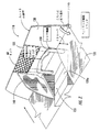
図1を参照すると、車両室12内に物品を収納するための本発明の参考例による組立式収納装置10が示されている。図示の車両室12は自動車のトランクである。しかし、当然のことながら、本発明の参考例は、ミニバン、トラック及び/又はスポーツ・ユーティリティ・ビークルの後部収納区域のような種々の車両の車室において制限なく使用することが可能である。図示の車両室12は、フロア敷物(例えば、カーペット、マット等)16を有する積載フロア(以後、"フロア"という)14と、このフロア14から実質的に垂直に延びる少なくとも1つの側壁18とを含んでいる。図示の車両室12は、フロア14及び側壁18により部分的に画成されている。しかし、他の壁体、背もたれ及びパッケージトレー(図示せず)が車両室12を更に画成していてもよい。
【0026】
図示の装置10は、フロア14の上に、或いは、少なくとも部分的にフロア14の下に配置されるベース20を含んでおり、このベース20は、装置10が使用位置(即ち、開位置)にあるときに車両室12に少なくとも部分的にさらされる表面22を有している。ベース20は、フロア敷物16のところに配置しても、或いはその下に配置してもよい。図示のベース20は、ほぼ矩形の形状を有し、フロア敷物16の全体よりも実質的に狭い範囲を占めており、側壁18に隣接して配置されている。しかし、ベース20は、円形、楕円形又は正方形のような任意の形状及び大きさを有していると共に、車両室12内のどこにでも配置することができる。ベース20がフロア敷物16の下方に配置されている場合、フロア敷物16は、装置10が使用位置(即ち、開位置)にあるときに表面22の少なくとも一部が車両室12に露出するように開口24を含んでいる。
【0027】
ベース20は、ほぼ平らな構造を有しており、及び/又は水平に対して傾斜した方向を有することができる。ある取り付けの場合、ベース20は、車両室内における金属薄板の形状に一致させてもよい。図2及び図3は、ベース110,210が傾斜構造の部分120a,220aを含む別の参考例による収納装置110,210を示している。
【0028】
本発明の参考例によると、車室内のフロア敷物は、"ベース"の役目を果たしている。そのようにしてあるので、後部パネルはフロア敷物に旋回式に取り付けられている。従って、ベース20は、別個の要素でもよいし、或いはフロア敷物でもよいし、或いはフロア自体とすることも可能である。
【0029】
図1に戻り参照すると、図示の装置10は、1つ以上の蝶番38を介してヒンジ式に取り付けられており、対峙する前側面32及び後側面34と、対峙する第1端部33a及び第2端部33bとを有する後部パネル30を含んでいる。この後部パネル30は、前側面32がベース表面22に対し覆い被さる対面関係にある閉位置と、後部パネル30がベース表面22に対して実質的に垂直に配置される開位置との間で移動可能となっている。開位置において、後部パネル30及びベース表面22は(以下に述べるエンドパネル39a,39bと一緒に)、内部に物品を受け入れるための収納室35を画成している。
【0030】
ベース20は、後部パネル30が閉位置にあるときにフロア14と実質的に同一平面にあるように、少なくとも部分的にフロア14の直下に配置されている。本発明の参考例によると、ベース20は、後部パネル30が閉位置にあるときにフロア敷物16の上に乗るように、フロア敷物16上に配置されている。
【0031】
後部パネル30をベース20に(又はフロア14に、又はベース20に隣接する他の車両要素に)旋回式に取り付けるため、殆どどんな形式の蝶番でも使用可能である。本発明の参考例によると、フロア敷物16(例えば、カーペット)は、フロア14の上に配置され、かつ後部パネル30の後側面34の上に配置されていると共に、蝶番としての機能を果たせるようになっている。ベース20は、後部パネル30が閉位置にあるときに、同後部パネル30とその上に配置されたフロア敷物16とがフロア14と同一平面にあるように、フロア14の実質的に直下に配置されている。従って、装置10は、後部パネル30が閉位置にあるときに、車両室のフロア14と一体であるように見えることになる。
【0032】
しかし、当然のことながら、本発明の参考例は、車両室のフロア又はフロア敷物と同一平面にある必要はない。更に、本発明の参考例は、フロア又はフロア敷物の上に直接に置くように構成されてもよい。
【0033】
図1に示した参考例を更に参照すると、第1のエンドパネル39a及び第2のエンドパネル39bは、後部パネル30の第1端部33a及び第2端部33bに移動可能に取り付けられている。第1のエンドパネル39a及び第2のエンドパネル39bは、後部パネルの前側面32に対して対面関係にある格納位置と、ベース表面22及び後部パネル30に対して実質的に垂直に配置される使用位置との間で移動可能となっている。第1のエンドパネル39a及び第2のエンドパネル39bは、後部パネル30がその閉位置から開位置へと移動するのに対応して、それぞれの格納位置から使用位置へ移動するものである。第1のエンドパネル39a及び第2のエンドパネル39bは、ベース表面22及び後部パネル30と一緒になって、内部に物品を受け入れるための収納室35を画成している。
【0034】
本発明の参考例によると、第1のエンドパネル39a及び第2のエンドパネル39bは、ベース表面22に旋回式に取り付けられていると共に、ベース表面22に対して対面関係にある格納位置と、ベース表面22及び後部パネル30に対して実質的に垂直に配置される使用位置との間で移動可能となっている。第1のエンドパネル39a及び第2のエンドパネル39bは、ベース表面22に直接に取り付けられていても(或いはその近くに取り付けられていても)、後部パネル30がその閉位置から開位置へ移動するのに対応して、それぞれの格納位置から使用位置へと移動するものである。
【0035】
更に図1を参照すると、図示の装置10は、後部パネル30の前側面32に移動可能に取り付けられた仕切パネル40も含んでいる。この仕切パネル40は、後部パネルの前側面32に対して対面関係にある格納位置と、ベース表面22及び後部パネル30に対して実質的に垂直に配置される使用位置との間で移動可能となっている。仕切パネル40は、後部パネル30がその閉位置から開位置へと移動するのに対応して、その閉位置から開位置へと移動するものである。或いは、仕切パネル40の移動は、後部パネル30の移動とは独立していてもよい。仕切パネル40は、使用位置にあるとき、収納室35を複数の室部分35a,35bに分割している。
【0036】
図示の参考例において、仕切パネル40は、装置10が開位置にあるときに第1のエンドパネル39a及び第2のエンドパネル39bとほぼ平行になっている。単一の仕切パネル40のみが図示されているが、言うまでもなく、複数の仕切パネルを本発明の参考例に従って利用することができる。
【0037】
仕切パネル40は、1つ以上の蝶番42aにより後部パネル30の前側面32に移動可能に取り付けられている。或いは、仕切パネル40は、1つ以上の蝶番42bによりベース表面22に移動可能に取り付けることができる。殆どどんな形式の蝶番でも仕切パネル40を後部パネルの前側面32又はベース表面22に移動可能に取り付けるのに使用できる。本発明の参考例は、蝶番の特別な形式に限定されるものではない。
【0038】
図1を更に参照すると、ハンドルもしくは取扱部70が仕切パネル40に付設されている。この取扱部70は、ユーザーにより把持されるように形成されており、後部パネル30を閉位置から開位置へと移動させ、それによりエンドパネル39a,39bをそれぞれの使用位置に移動させて内部に物品を受け入れるための収納室35を形成するのに使用されている。そして、取扱部70は、仕切パネル40をその使用位置に移動させて収納室35a,35bを形成するのに使用可能である。本発明の別の参考例によれば、取扱部70は後部パネル30に付設させることができる。種々の形状及び構成を有する取扱部が本発明の参考例に従って使用可能である。更に、取扱部は、種々の位置で仕切パネル40及び/又は後部パネル30に設置することが可能である。言うまでもなく、本発明の参考例は取扱部を必要としない(即ち、取扱部は任意である)。
【0039】
本発明の更なる参考例によると、図1に示すように、1つ以上の突起部50(例えば、フック)を設けることができ、これは後部パネルの前側面32から延びている。各突起部50は、そこから懸架される食料雑貨品の入ったバッグのような物品を支持するように構成されている。
【0040】
本発明の更なる参考例によると、図1に示すように、収納室35及び/又は収納室35a,35bとその内部に収納された物品とを囲むように構成された荷物用ネット60は、後部パネル30に取り付けることが可能である。
【0041】
使用中、図1の組立式装置10が内部に取り付けられた車両の車両室12に物品を積載し運搬したい場合、装置10は、取扱部70の簡単な動作により、格納位置から移動されて開位置にカチッと入る。本発明の参考例によると、後部パネル40、エンドパネル39a,39b及び仕切パネル40は、ロックされた方向にカチッと入って、装置10を閉じる必要が生じるまで、確実に所定位置に留められることになる。
【0042】
格納位置から使用位置への仕切パネル40の移動により、後部パネル30を閉位置から開位置へ移動させることができ、これにより第1のエンドパネル39a及び第2のエンドパネル39bがそれぞれの格納位置から使用位置へと移動することになる。或いは、格納位置から使用位置への後部パネル30の移動により、第1のエンドパネル39a及び第2のエンドパネル39bをそれぞれの格納位置から使用位置へと移動させてもよい。仕切パネル40の作動は、後部パネル30の移動とは独立していてもよい。
【0043】
装置10がその内部に物品を収納しておくのに使用する必要がもはやないときには、上述した手順を逆に行えばよい。例えば、どの追加の仕切パネルも旋回させて、ベース表面22又は後部パネルの前側面32のどちらかに当接配置させ、次いで後部パネル30を閉位置に移動させることにより、エンドパネル39a,39bをそれぞれの閉位置に移動させることができる。従って、本発明の参考例による装置は、格納位置、閉位置から開位置、使用位置に迅速且つ容易に移動することができる。
【0044】
図2を参照すると、車両室内に物品を収納するための本発明の別の参考例による組立式収納装置110が示されている。図示の装置110は、傾斜構造の部分120aを有するベース120を含んでいる。後部パネル130は、ベース120に移動可能に取り付けられていると共に、図示のように、その一部に形成された開口131を有している。荷物用ネット60は、後部パネルの開口131を横断して広がり、後部パネル130とベースの傾斜した部分120aとにより画成された収納室135内にユーザーが物品を置くことを可能にしている。また、後部パネル130又はベース120のどちらかに移動可能に取り付けられる仕切パネル140も設けられている。上述したように、仕切パネル140は、格納位置と使用位置との間を移動可能である。
【0045】
また、装置110の後部パネル130を開位置に保持するためにロック部材150が設けられている。図示のロック部材150は、ベース120に対して上下動するように構成されている。後部パネル130が開位置に移動されるときに、ロック部材150が下方に移動し、後部パネル130を開位置に保持している。後部パネル130を閉位置へと下降させるためには、ロック部材150を上方に移動させると、後部パネル130が旋回可能になる。種々の構成を有する種々のロック部材が本発明の参考例に従い利用し得るものである。本発明の参考例は、図示のロック部材150に限定されるものでない。
【0046】
図4を参照すると、車両室内に物品を収納するための本発明の代替参考例による組立式収納装置310が示されている。図示の装置310は、隣接してはいるが離間した関係でベース表面322に(或いはその近くに)移動可能に取り付けられた一対の仕切パネル340a,340bを含んでいる。各仕切パネル340a,340bは、ベース表面322に対して対面関係にある格納位置と、収納室335を複数の部分に分けるようにベース表面322及び後部パネル340に対して実質的に垂直に配置される使用位置との間で移動可能となっている。対の仕切パネル340a,340bには、部材350を介してハンドルもしくは取扱部370が回転自在に接続されている。この取扱部370は、ユーザーにより把持されて仕切パネル340a,340bを格納位置から使用位置に動かすように構成されている。
【0047】
仕切パネル340a,340bを格納位置から使用位置に動かすために、ユーザーは、ベース表面322に対して対面関係で置かれた取扱部370を掴み、矢印A1で示されたように取扱部370を回転させ、矢印A2で示されたように引き上げる。仕切パネル340a,340bは、矢印A2で示された運動に追従し、それぞれ矢印A3,A4により示されたように使用位置へと移動することになる。
【0048】
必要のない場合には、仕切パネル340a,340bは、上述の操作を逆に行うことにより、格納位置へ戻すことができる。本願発明の参考例によると、仕切パネル340a,340b及び取扱部370は、格納時に、ベース322の内側に水平装着の形態で保持し得るようになっている。しかし、仕切パネル340a,340b及び取扱部370を、格納時に、ベース322の内側に水平装着の形態で保持することが要求されるものではない。
【0049】
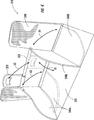
次に、図5A及び図5Bを参照すると、車両室12内に物品を収納するための本発明の他の参考例による組立式収納装置410が示されている。この装置410は、車両室12のフロア14上に配置されたベース420を含んでいる。ベース420は、向かい合う第1の端部421a及び第2の端部421bと、向かい合う第1の縁部421c及び第2の縁部421dと、車両室12に露出する表面422とを含んでいる。第1及び第2の伸張式壁体425a,425bは、それぞれ第1の端部421a及び第2の端部421bから延びると共に、パネル430に取り付けられている。
【0050】
パネル430は、ベース420に枢着されると共に、第1の端部430a及び第2の端部430bを含んでいる。これら第1の端部430a及び第2の端部430bはそれぞれ第1の伸張式壁体425a及び第2の伸張式壁体425bに接続されている。図示のパネル430は、貫通形成された開口431を含んでおり、この開口431の上側には荷物用ネット60が掛かっている。
【0051】
パネル430は、ベース表面422に対して覆い被さる対面関係にある閉位置(図5A)と、ベース表面422に対し実質的に交差配置される開位置(図5B)との間で移動可能となっている。ベース422、第1の伸張式壁体425a及び第2の伸張式壁体425bとパネル430は、内部に物品を受け入れるための1つ以上の収納室を画成している。
【0052】
図示の伸張式壁体425a,425bの各々は、第1端部426aで一緒にピン留めされていると共に、反対側に自由端426bを有する複数の部材426を含んでいる。各伸張式壁体425a,425bの部材426は、パネル430が閉位置(図5A)から開位置(図5B)へと移動するときに、積み重なった積重関係(図5A)から扇形に広がった関係(図5B)に移動するように構成されている。
【0053】
本発明の参考例は図示の伸張式壁体425a,425bに限定されない。種々の形式及び構成の伸張式及び組立式壁体を使用することが可能である(例えば、入れ子式壁体、アコーディオン式のベローズを有する壁体等)。
【0054】
図6A及び図6Bに示すように、解除可能にパネル430を開位置に固定するためにロック部材450が設けられている。ロック部材450は、各伸張式壁体425a,425bについて設けてもよく、或いは一つの伸張式壁体(即ち、425a又は425b)についてだけ設けてもよい。図示のロック部材450は、第1及び第2の細長いアーム451,452を含み、各アームが両端に第1端部451a,451b及び第2端部452a,452bを有している。第1のアームの第1端部451aは、ベース420又はその近くに枢着される。第2のアームの第1端部452aはパネル430に枢着されている。第1及び第2のアーム451,452の第2端部451b,452bは、互いに枢着されている。
【0055】
パネル430を開位置にロックするために、第1及び第2のアーム451,452の第2端部451b,452bが引き上げられると、ロック部材450の構成によりベース420に向かうパネル430の移動が阻止されるようになっている(図6A)。パネル430を開位置からアンロック(もしくは解除)してパネル430が閉位置に移動するのを許容するため、図6Bに示すように、下向きの力Fが第1及び第2のアーム451,452の第2端部451b,452bに加えられることになる。そして、各伸張式壁体425a,425bの部材426は、パネル430が閉位置へ移動するにつれて、扇形に広がった関係から積重関係に移動することが可能になる。
【0056】
図7A及び図7Bを参照すると、車両室内に物品を収納するための本発明の他の参考例による組立式収納装置510が示されている。この装置510は、車両室12のフロア14上に配置されるベース520を含んでいる。ベース520は、向かい合う第1端部521a及び第2端部521bと、向かい合う第1縁部521c及び第2縁部521dと、車両室12に露出する表面522とを含んでいる。荷物用弾性ネット525a,525bは、それぞれ第1端部521a及び第2端部521bに隣接してベース表面522から延びると共に、パネル530に取り付けられている。
【0057】
パネル530は、ベース520に枢着されていると共に、対向する第1端部530a及び第2端部530bを含んでいる。これら第1端部530a及び第2端部530bは、荷物用弾性ネット525a,525bに連結されている。パネル530は、ベース表面522に対して覆い被さる対面関係にある閉位置(図7A)と、ベース表面522に対し実質的に交差配置される開位置(図7B)との間で移動可能となっている。ベース522、荷物用弾性ネット525a,525b及びパネル530は、内部に物品を受け入れるための1つ以上の収納室を画成している。
【0058】
本発明の参考例は荷物用弾性ネットに限定されない。種々の形式の弾性部材を利用することが可能である。
【0059】
次に図8A及び図8Bを参照すると、車両室12内に物品を収納するための本発明の他の参考例による組立式収納装置610が示されている。この装置610は、物品を収納できる2つの収納室635a,635bを含んでいる。第1収納室635aは、車両フロア14、一対の伸張式壁体625a,625b及びパネル630により画成されている。収納室635aの上側にあるパネル630の部分は、貫通形成された開口631を含んでおり、荷物用ネット60がこの開口631に覆い被さっている。第2収納室635bは、ベース620、一対の伸張式壁体625b,625c及びパネル630により画成されている。
【0060】
図示の伸張式壁体625a,625b,625cの各々は、第1端部626aで一緒にピン留めされていると共に、反対側にある自由端626bを有する複数の部材626を含んでいる。各伸張式壁体625a,625bの部材626は、前述したように、パネル630が閉位置(図8A)から開位置(図8B)へと移動するときに、積重関係(図8A)から扇形に広がった関係(図8B)に移動するように構成されている。
【0061】
本発明の参考例は、図示の伸張式壁体625a,625b,625cに限定されない。種々の形式及び構成の伸張式及び組立式壁体を使用することが可能である(例えば、入れ子式壁体、アコーディオン式のベローズを有する壁体等)。
【0062】
図9を参照すると、車両室12'内に物品を収納するための本発明の他の参考例による組立式収納装置710が示されている。図9において開位置に示されている装置710は、車両室12'内に枢着されている(例えば、ベース又はフロア敷物又はフロアに取り付けられている)後部パネル730を含んでおり、この後部パネル730は、フロア(又はベース又はフロア敷物)と協働して収納室735を画成している。付勢装置713は、後部パネル730と車両フロア(又は車両室12'の他の部分)とに取り付けられており、後部パネル730を開位置に付勢するように構成されている。図示の付勢装置713は、自動車産業分野でハッチバックドア、ボンネット等を支持するのに使用されている形式の伸縮式緩衝装置もしくは支柱(例えば、ガス、ハイドロリック)である。この伸縮式緩衝装置は当業者に良く知られており、ここで更に説明する必要はない。また、図示の付勢装置713は、後部パネル730を開位置に解除可能に保持するように構成されたロック部材の機能も果たすことができる。或いは、付勢装置713は、後部パネル730を開位置から閉位置に付勢すると共に、後部パネル730を閉位置に維持するのに役立つように構成されていてもよい。
【0063】
言うまでもなく、同一又は異なる機能を奏する追加の付勢装置を使用することができる。例えば、1つ以上の付勢装置を設けて後部パネル730を開位置に付勢してもよいし、また、1つ以上の付勢装置を設けて後部パネル730を閉位置に付勢してもよい。
【0064】
本発明の参考例に従って種々の形式の付勢装置を使用することが可能である。本発明の参考例は、伸縮式緩衝装置に限定されない。ばね、ダンパー及びその他既知の付勢装置も制限なしに使用することが可能である。
【0065】
また、図9の装置710は、車両のフロア(又はベースもしくはフロア敷物)と後部パネル730の前側面732とに取り付けられた可撓性材料715も含んでおり、この可撓性材料715は、後部パネル730が開位置に移動するときに収納室735を複数の室部分735a,735b,735cに分割するものである。具体例としての可撓性材料715は荷物用ネットでもよい。しかし、本発明の参考例は荷物用ネットに限定されない。種々の材料を制限なしに使用することができる。
【0066】
図10A及び図10Bを参照すると、車両室12'内に物品を収納するための本発明の更なる実施例による組立式収納装置810が開位置で示されている。図10A及び図10Bにおいて、開位置で示されている装置810は、車両室12'内に隣接離間した関係で枢着されている(例えば、ベースもしくはフロア敷物又はフロアに取り付けられている)複数の細長いパネル830を含んでおり、該パネル830は、フロア(又はベースもしくはフロア敷物)と協働して複数の収納室835を画成している。図示のパネル830は、ほぼ平行に離間された関係にある。
【0067】
各パネル830は、対向する前側面832及び後側面834を含んでいる。これらパネル830は、閉位置及び開位置間で一括して移動可能となっている。閉位置において、各パネル830の前側面832は、車両のフロア(又はベースもしくはフロア敷物)に覆い被さる対面関係にある。開位置において、パネル830は、車両フロア(又はベースもしくはフロア敷物)に対して実質的に交差するように集合的に配置され、内部に物品を受け入れるための複数の収納室835を画成している。
【0068】
図示の実施例において、これらパネル830は、各パネル830に移動可能に装着された部材831を介して閉位置及び開位置間を一括して移動できるようになっている。図示実施例において、部材831は、その各端部近くで各パネル830に移動可能に装着されている。しかし、言うまでもなく、該部材831は各パネル830に種々の個所で移動可能に取り付けられる。更に、部材831は、種々の構成をもつことができる。ハンドルもしくは取扱部833は、部材831に取り付けられていると共に、該部材831を動かすことによりパネル830を閉位置及び開位置間で一括して移動させるため、ユーザーにより把持されるように構成されている。
【0069】
本発明の更なる実施例によると、パネル830を開位置に付勢するように構成された少なくとも1つの付勢装置(図示せず)を1つ以上のパネル830に取り付けてもよい。また、フロア敷物を車両室のフロアに設けることができる。パネル830が一括して閉位置にあるとき、装置810が車両室12'と一体的な外観を有するように、同じフロア敷物を1つ以上のパネル830の後側面834に設けることができる。
【0070】
図11A及び図11Bを参照すると、車両室12'内に物品を収納するための本発明の更なる参考例による組立式収納装置910が示されている。この装置910は、車両室のフロア(又はフロア敷物もしくはベース)に脚部材941を介して枢着される細長いパネル930を含んでいる。パネル930は、フロア(又はフロア敷物もしくはベース)と実質的に接触する対面関係にある格納位置と、パネル930がフロア(又はフロア敷物又はベース)と離間した対面関係にある使用位置との間で移動可能となっている。使用位置において、パネル930はテーブル及び/又は棚の機能を果たすことができる。図示の参考例において、ハンドルもしくは取扱部933は、パネル930に接続されていると共に、ユーザーにより把持されてパネル930を格納位置及び使用位置間で動かせるように構成されている。
【0071】
図12A,図12B,図13A,図13B,図14A,図14B及び図15を参照すると、車両室内に物品を収納するための組立式収納装置1010の諸参考例が示されている。図示の各参考例において、各装置1010は、車両のフロア(又はベースもしくはフロア敷物)に枢着される複数の壁体1030を含んでいる。壁体1030は、折畳まれた平らな配置ではフロア(又はベース又はフロア敷物)に覆い被さり、広げると内部に物品を受け入れるための1つ以上の収納室1035になるように構成されている。図示の各参考例において、ハンドルもしくは取扱部1033が壁体1030の1つに接続されており、この取扱部1033は、ユーザーにより把持されるように構成されていると共に、種々の壁体1030の1つ以上を広げて1つ以上の収納室1035にするのに使用されている。
【0072】
この明細書において例示し説明した収納装置の各参考例は、車両室内に容易に設置できると共に、そこから容易に除去可能であるように可搬式にすることができる。本発明の実施例及び諸参考例は自動車のトランク内への設置に関連して例示し説明されているが、本発明の実施例及び参考例による装置が種々の形式の車両のその他種々の収納室及び区域に設置可能であることは言うまでもない。
【0073】
以上は、本発明を説明するためであって、本発明を限定するものと解釈すべきではない。本発明の典型的な実施例について説明してきたが、当業者なら容易に分かるように、本発明の新規な教示内容及び利点から実質的に逸脱することなく、典型的な実施例には多くの改変が可能である。従って、このような改変の全ては、特許請求の範囲に記載された本発明の範囲に含まれるものと考えられる。それ故、当然のことながら、以上は、本発明を説明するためであって、開示された特定の実施例に限定されるものと解釈すべきではなく、また、言うまでもなく、開示された実施例だけでなく、その他の実施例に対する改変も特許請求の範囲に含まれると解釈されるべきである。本発明の範囲は冒頭の特許請求の範囲により画定されており、同特許請求の範囲の相当語句も本発明の範囲に含まれている。
【図面の簡単な説明】
【図1】 車両室内に物品を収納するための本発明の参考例による組立式収納装置の斜視図である。
【図2】 車両室内に物品を収納するための本発明の他の参考例による組立式収納装置の斜視図である。
【図3】 車両室内に物品を収納するための本発明の他の参考例による組立式収納装置の斜視図である。
【図4】 車両室内に物品を収納するための本発明の他の参考例による組立式収納装置の斜視図である。
【図5A】 車両室内に物品を収納するための本発明の他の参考例による組立式収納装置の斜視図であり、閉位置にある収納装置を示している。
【図5B】 車両室内に物品を収納するための本発明の他の参考例による組立式収納装置の斜視図であり、開位置にある収納装置を示している。
【図6A】 可動のパネルを開位置に解除可能に固定するように構成されたロック部材を示す図5A及び図5Bの装置の側面図であり、ベースに向かうパネルの移動を阻止するようにロック位置にあるロック部材を示している。
【図6B】 可動のパネルを開位置に解除可能に固定するように構成されたロック部材を示す図5A及び図5Bの装置の側面図であり、パネルがベースに向かい閉位置へと移動するのをロック部材が許容するように第1及び第2のアームの第2端部に力が加えられている状態を示している。
【図7A】 車両室内に物品を収納するための本発明の他の参考例による組立式収納装置の斜視図であり、閉位置にある収納装置を示している。
【図7B】 車両室内に物品を収納するための本発明の他の参考例による組立式収納装置の斜視図であり、開位置にある収納装置を示している。
【図8A】 車両室内に物品を収納するための本発明の他の参考例による組立式収納装置の
斜視図であり、閉位置にある収納装置を示している。
【図8B】 車両室内に物品を収納するための本発明の他の参考例による組立式収納装置の斜視図であり、開位置にある収納装置を示している。
【図9】 車両室内に物品を収納するための本発明の更なる参考例による組立式収納装置の斜視図である。
【図10A】 車両室内に物品を収納するための本発明の付加的な実施例による組立式収納装置の斜視図である。
【図10B】 図10Aの組立式収納装置の側面図である。
【図11A】 車両室内に物品を収納するための本発明の更なる参考例による組立式収納装置の斜視図である。
【図11B】 図11Aの組立式収納装置の側面図である。
【図12A】 本発明の他の参考例による組立式収納装置を示している。
【図12B】 本発明の他の参考例による組立式収納装置を示している。
【図13A】 本発明の他の参考例による組立式収納装置を示している。
【図13B】 本発明の他の参考例による組立式収納装置を示している。
【図14A】 本発明の他の参考例による組立式収納装置を示している。
【図14B】 本発明の他の参考例による組立式収納装置を示している。
【図15】 本発明の他の参考例による組立式収納装置を示している。[0001]
[Field of the Invention]
The present invention relates generally to vehicles, and more particularly to a luggage management device for use within a vehicle.
[0002]
[Related applications]
This application claims the benefit of US Provisional Application No. 60 / 214,947, filed Jun. 29, 2000, the entire contents of which are hereby fully incorporated by reference. Are incorporated herein.
BACKGROUND OF THE INVENTION Automobiles generally have some form of luggage storage room. For example, sedan-type automobiles are conventionally equipped with a trunk. Sport utility vehicles and minivan vehicles with two or more rows conventionally have a luggage storage area behind the last row of seats.
[0004]
Articles that are carried into the luggage storage area of the vehicle often move freely during vehicle operation, which is undesirable. The luggage net can be used to suppress the movement of the article in the luggage storage room of the vehicle. Such a net appropriately suppresses the movement of the article, but two arms are necessary to pull the net while the article is in the net, which is troublesome.
[0005]
The vehicle storage room is divided to prevent movement of articles stored in the vehicle storage room.
Various devices are known. For example, a storage system for a vehicle luggage compartment disclosed in U.S. Pat. A cover configured to rotate between an open position and a closed position; U.S. Pat. No. 5,669,537, issued to Saleem et al., Describes a storage unit that extends between and couples to vehicle panels in a vehicle storage area. U.S. Pat. No. 5,501,384 to Wisnysky et al. Describes a vehicle storage system that includes a molded box and a cover pivotally attached to the molded box.
[0006]
Unfortunately, these devices are somewhat complex and bulky and are not adapted for compact storage in the luggage storage area of a vehicle. In addition, luggage storage space may be somewhat limited in automobiles such as sports utility vehicles and minivans. Accordingly, the luggage storage device can reliably hold the article in the luggage storage area while the vehicle is in operation, and can easily be removed from the baggage storage area without being disturbed when necessary. There is a need for storage. In addition, there is a need to make the best use of existing luggage storage areas without interrupting passenger space.
[0007]
[Summary of Invention]
In view of the above description, a prefabricated storage device is provided for use in a vehicle compartment (eg, a luggage compartment such as a car trunk, minivan, and SUV). Of the present invention reference According to an example, the storage device includes a base arranged on the floor (or rug on the floor) of the vehicle compartment. The base includes a surface that is at least partially exposed to the vehicle compartment when the device is in the use position. The base may be a generally flat structure, or one or more portions thereof may have an orientation that is inclined relative to the horizontal. The rear panel is pivotally mounted on the base and has a closed position in which the rear panel covers over the surface of the base and an open position in which the rear panel is disposed substantially perpendicular to the surface of the base. It is possible to move between. In the open position, the rear panel and base surfaces define a storage chamber for receiving articles therein.
[0008]
Of the present invention reference According to an example, the base is partially located directly below the floor, and the rear panel is substantially flush with the floor when in the closed position. Of the present invention reference According to an example, the base is arranged on the floor covering so that it is on the floor covering when the rear panel is in the closed position.
[0009]
Of the present invention reference The example does not require a separate element as a base. The floor or floor covering in the vehicle compartment can serve as a “base”. Furthermore, the present invention reference By way of example, as described herein, the rear panel need not be substantially flush with the vehicle floor (or floor covering) when in the closed position.
[0010]
Of the present invention reference According to an example, the floor covering material may be placed on the floor of the vehicle compartment and on the rear side of the rear panel, and also serves as a hinge. The base is sufficiently below the floor of the vehicle compartment so that when the rear panel is in the closed position, the rear panel and the floor covering placed thereon are substantially flush with the floor of the vehicle compartment and the floor covering. It is arranged.
[0011]
Of the present invention reference According to an example, an end panel is movably attached to each end of the rear panel. The end panel is movable between a retracted position facing the rear panel and a use position positioned substantially perpendicular to the surface of the base and the rear panel. These end panels are adapted to move from their respective storage positions to use positions in response to the movement of the rear panel from the closed position to the open position. Alternatively, the end panel is pivotally attached to the surface of the base and is movable between a retracted position facing the surface of the base and a use position positioned substantially perpendicular to the surface of the base and the rear panel. It is.
[0012]
Of the present invention reference By way of example, one or more divider panels can be provided that are movably attached to either the rear panel or the surface of the base. When each partition panel is in the use position, the storage chamber can be divided into a plurality of chamber portions. Each partition panel is movable between a storage position facing the rear panel (or surface of the base) and a use position disposed substantially perpendicular to the surface of the base and the rear panel. Each partition panel moves from the closed position to the open position in response to the rear panel moving from the closed position to the open position. Alternatively, the movement of the partition panel may be independent of the movement of the rear panel. Other of the present invention reference By way of example, the one or more divider panels may be removable and may be configured to be attached to the rear panel at a variety of different locations.
[0013]
Of the present invention reference According to an example, the handling part can be attached to a partition panel (or rear panel), which is handled by a user and used to move the rear panel from the closed position to the open position. Accordingly, the partition panel and / or the end panel are moved to the respective use positions, and a storage chamber for receiving articles is defined therein.
[0014]
Further of the present invention reference According to an example, one or more protrusions (eg, hooks) can be provided that extend from the rear panel. Each such protrusion is configured to support an item such as a bag of grocery items suspended therefrom.
[0015]
Another of the present invention reference According to an example, a luggage net configured to surround a storage room and an article stored in the storage room is attached to a rear panel.
[0016]
Of the present invention reference According to an example, one or more locking members and / or springs are provided to maintain the rear panel in the open position. In addition, the use of a biasing device can assist in opening the rear panel, and the biasing device includes, but is not limited to, a spring, a telescopic shock absorber, a damper, and the like. .
[0017]
Of the present invention Fruit According to an embodiment, the storage device includes a plurality of elongated panels that are pivotally mounted adjacent to each other in the vehicle compartment, the panels defining a plurality of storage chambers. The panel is collectively movable between a closed position and an open position. In the closed position, the front side of each panel is in a facing relationship over the vehicle floor (or base or floor covering). In the open position, the panels are collectively arranged to substantially intersect the vehicle floor (or base or floor covering) and define a plurality of storage chambers for receiving articles therein. ing.
[0018]
Further of the present invention reference According to an example, an apparatus for storing articles in a vehicle compartment includes an elongated panel that is pivotally attached to the floor (or floor covering or base) of the vehicle compartment via leg members. The panel moves between a retracted position that is in contact with the floor (or base or floor covering) and a working position in which the panel is spaced apart from the floor (or base or floor covering). Is possible. In the use position, the panel can serve as a table and / or shelf.
[0019]
The assembly-type device according to the present invention is configured to be able to be operated using only one hand from a folded (ie, closed) position to an extended (ie, open) position and vice versa. The device according to the present invention is adapted to be moved from the storage position and clicked into the open position by a simple operation by lifting and turning the handle or the handling portion. The rear panel, end panel, and partition panel are configured to snap into a locked orientation, so that they will reliably remain in place until it is necessary to close the device. Of the present invention reference If the apparatus according to the example is no longer to be used for storing articles therein, the above procedure can be reversed. Therefore, the present invention reference The device according to the example can be moved quickly and easily from the stored closed position to the open use position.
[0020]
Further of the present invention reference According to an example, a prefabricated device for storing articles in a vehicle compartment includes a base, first and second extendable walls and panels. The panel is pivotally attached to the base and connected to the first and second extendable walls. The panel is movable between a closed position covering the base and an open position configured to substantially intersect the base. Of the present invention reference According to an example, the panel includes an opening formed therethrough, which is covered with a luggage net.
[0021]
The vehicle storage device according to the present invention can be integrated with the floor covering and can be manufactured at least partly from the same material as the floor covering in the vehicle compartment, so that the device has the appearance of the floor covering. It can be folded on the floor covering with little change.
[0022]
Furthermore, the present invention reference The storage device according to the example can be quickly folded into a flat state so that the storage device does not get in the way when not in use and / or when a larger device needs to be stored in the luggage storage area It is possible to put it away like this.
[0023]
Detailed Description of the Invention
The present invention will now be described in detail with reference to the accompanying drawings showing preferred embodiments of the invention. However, the present invention may be implemented in various forms and should not be construed as limited to the examples described herein, but rather Fruit The examples are provided so that the disclosure is complete and the disclosure fully conveys the scope of the invention to those skilled in the art.
[0024]
In the drawings, the thickness of various lines, the thickness of each layer, and the density of areas may be exaggerated for clarity. Of course, when an element such as a layer, area, substrate or panel is referred to as being “on” or “in contact with” another element, the element directly touches another element. There may be contact or there may be intervening elements. In contrast, when one element is referred to as being “in direct contact with” another element, there are no intervening elements present. Of course, when an element is referred to as being “coupled or connected” or “attached or attached” to another element, the element may be directly connected to or attached to another element. Alternatively, intervening elements may be present. In contrast, when an element is referred to as being “directly coupled or connected” or “directly attached or attached” to another element, there are no intervening elements present. In this specification, the terms “upper”, “lower”, “vertical”, “horizontal”, etc. are used for illustrative purposes only.
[0025]
Referring to FIG. 1, the present invention for storing articles in a
[0026]
The illustrated apparatus 10 includes a base 20 that is disposed on the
[0027]
The
[0028]
Of the present invention reference According to the example, the floor covering in the passenger compartment serves as the “base”. As such, the rear panel is pivotally attached to the floor covering. Thus, the
[0029]
Referring back to FIG. 1, the illustrated device 10 is hingedly attached via one or more hinges 38, facing
[0030]
The
[0031]
Almost any type of hinge can be used to pivotally attach the
[0032]
However, it should be understood that the present invention reference The example need not be coplanar with the vehicle room floor or floor covering. Furthermore, the present invention reference Examples may be configured to be placed directly on the floor or floor covering.
[0033]
As shown in FIG. reference Still referring to the example, the
[0034]
Of the present invention reference According to an example, the
[0035]
Still referring to FIG. 1, the illustrated apparatus 10 also includes a
[0036]
Illustrated reference In the example, the
[0037]
The
[0038]
Still referring to FIG. 1, a handle or handle 70 is attached to the
[0039]
Further of the present invention reference According to an example, as shown in FIG. 1, one or more protrusions 50 (eg, hooks) can be provided, which extend from the
[0040]
Further of the present invention reference According to the example, as shown in FIG. 1, the luggage net 60 configured to surround the
[0041]
In use, when it is desired to load and carry articles in the
[0042]
By moving the
[0043]
When the device 10 no longer needs to be used to store items therein, the above procedure may be reversed. For example, any
[0044]
Referring to FIG. 2, another embodiment of the present invention for storing articles in a vehicle compartment. reference An example
[0045]
A locking
[0046]
Referring to FIG. 4, an alternative to the present invention for storing articles in the vehicle compartment. reference An example
[0047]
In order to move the
[0048]
When it is not necessary, the
[0049]
Next, referring to FIGS. 5A and 5B, another embodiment of the present invention for storing articles in the
[0050]
[0051]
[0052]
Each of the illustrated
[0053]
Of the present invention reference The examples are not limited to the
[0054]
As shown in FIGS. 6A and 6B, a
[0055]
When the second ends 451b and 452b of the first and
[0056]
Referring to FIGS. 7A and 7B, another embodiment of the present invention for storing articles in a vehicle compartment is shown. reference An example
[0057]
[0058]
Of the present invention reference Examples are not limited to luggage elastic nets. Various types of elastic members can be used.
[0059]
8A and 8B, another embodiment of the present invention for storing articles in the
[0060]
Each of the illustrated
[0061]
Of the present invention reference Examples are not limited to the illustrated
[0062]
Referring to FIG. 9, another embodiment of the present invention for storing articles in the
[0063]
Of course, additional biasing devices that perform the same or different functions can be used. For example, one or more biasing devices may be provided to bias the
[0064]
Of the present invention reference Various types of biasing devices can be used in accordance with the examples. Of the present invention reference Examples are not limited to telescopic shock absorbers. Springs, dampers and other known biasing devices can also be used without limitation.
[0065]
9 also includes a
[0066]
Referring to FIGS. 10A and 10B, an assembled
[0067]
Each
[0068]
In the illustrated embodiment, these
[0069]
According to further embodiments of the present invention, at least one biasing device (not shown) configured to bias
[0070]
Referring to FIGS. 11A and 11B, the present invention for storing articles in the
[0071]
Referring to FIGS. 12A, 12B, 13A, 13B, 14A, 14B, and 15, various types of assembling-
[0072]
Each of the storage devices illustrated and described in this specification reference The example can be portable so that it can be easily installed in the vehicle compartment and removed from it easily. Of the present invention Examples and various reference Although examples have been illustrated and described in connection with installation in a car trunk, embodiments of the present invention And reference examples It goes without saying that the apparatus according to can be installed in various other storage rooms and areas of various types of vehicles.
[0073]
The foregoing is for the purpose of illustrating the invention and should not be construed as limiting the invention. Of the present invention Classic While typical embodiments have been described, it will be readily apparent to those skilled in the art that many modifications can be made to the exemplary embodiments without substantially departing from the novel teachings and advantages of the present invention. It is. Accordingly, all such modifications are considered to be within the scope of this invention as set forth in the claims. Therefore, it should be understood that the foregoing is for the purpose of illustrating the present invention and should not be construed as limited to the particular embodiments disclosed, and of course, disclosed embodiments. In addition, modifications to other embodiments should be construed as included in the claims. The scope of the present invention is defined by the appended claims, and equivalent terms of the claims are also included in the scope of the present invention.
[Brief description of the drawings]
FIG. 1 shows an embodiment of the present invention for storing articles in a vehicle compartment. reference It is a perspective view of the assembly-type storage apparatus by an example.
FIG. 2 shows another embodiment of the present invention for storing articles in a vehicle compartment. reference It is a perspective view of the assembly-type storage apparatus by an example.
FIG. 3 shows another embodiment of the present invention for storing an article in a vehicle compartment. reference It is a perspective view of the assembly-type storage apparatus by an example.
FIG. 4 shows another embodiment of the present invention for storing articles in a vehicle compartment. reference It is a perspective view of the assembly-type storage apparatus by an example.
FIG. 5A shows another embodiment of the present invention for storing an article in a vehicle compartment. reference FIG. 2 is a perspective view of an assembly storage device according to an example, showing the storage device in a closed position.
FIG. 5B shows another embodiment of the present invention for storing an article in a vehicle compartment. reference FIG. 2 is a perspective view of an assembled storage device according to an example, showing the storage device in an open position.
6A is a side view of the device of FIGS. 5A and 5B showing a locking member configured to releasably secure a movable panel in an open position, locked to prevent movement of the panel toward the base. FIG. The locking member in position is shown.
6B is a side view of the device of FIGS. 5A and 5B showing the locking member configured to releasably secure the movable panel in the open position, with the panel moving toward the base and into the closed position; FIG. In this state, a force is applied to the second ends of the first and second arms so that the lock member allows the above.
FIG. 7A shows another embodiment of the present invention for storing an article in a vehicle compartment. reference FIG. 2 is a perspective view of an assembly storage device according to an example, showing the storage device in a closed position.
FIG. 7B shows another embodiment of the present invention for storing an article in a vehicle compartment. reference FIG. 2 is a perspective view of an assembled storage device according to an example, showing the storage device in an open position.
FIG. 8A shows another embodiment of the present invention for storing an article in a vehicle compartment. reference Example of assembly type storage device
FIG. 4 is a perspective view showing the storage device in a closed position.
FIG. 8B shows another embodiment of the present invention for storing an article in a vehicle compartment. reference FIG. 2 is a perspective view of an assembled storage device according to an example, showing the storage device in an open position.
FIG. 9 shows a further embodiment of the present invention for storing articles in the vehicle compartment. reference It is a perspective view of the assembly-type storage apparatus by an example.
10A is a perspective view of a prefabricated storage device according to an additional embodiment of the present invention for storing articles in a vehicle compartment. FIG.
10B is a side view of the assembly-type storage device of FIG. 10A.
FIG. 11A is a further illustration of the present invention for storing articles in a vehicle compartment. reference It is a perspective view of the assembly-type storage apparatus by an example.
11B is a side view of the assembly-type storage device of FIG. 11A.
FIG. 12A shows another embodiment of the present invention. reference Fig. 2 shows an assembly storage device according to an example.
FIG. 12B shows another embodiment of the present invention. reference Fig. 2 shows an assembly storage device according to an example.
FIG. 13A shows another embodiment of the present invention. reference Fig. 2 shows an assembly storage device according to an example.
FIG. 13B shows another embodiment of the present invention. reference Fig. 2 shows an assembly storage device according to an example.
14A shows another embodiment of the present invention. reference Fig. 2 shows an assembly storage device according to an example.
FIG. 14B shows another embodiment of the present invention. reference Fig. 2 shows an assembly storage device according to an example.
FIG. 15 shows another embodiment of the present invention. reference Fig. 2 shows an assembly storage device according to an example.
Claims (4)
隣接した離間関係で前記フロアに枢着されている複数の細長いパネルを備え、各パネルは、対向する前側面及び後側面を備え、かつ前記各パネルには、部材が移動可能に装着され、該部材には取扱部が取り付けられ、該取扱部で前記部材を動かすことにより、前記複数のパネルが閉位置及び開位置の間を一括して移動可能であり、各パネルの前記前側面は、前記閉位置にあるときに前記フロアと覆い被さる対面関係にあり、前記複数のパネルは、前記開位置にあるときに前記フロアに対して実質的に交差するように一括して配置され、内部に物品を受け入れるための複数の収納室を画成し、前記開位置にある複数のパネルによって画成される前記複数の収納室は、車両の幅方向に延在し、車両の前後方向に間隔を置いて配設されている、装置。An apparatus for storing articles in a vehicle room including a floor,
A plurality of elongated panels pivotally attached to the floor in adjacent spaced relation, each panel having opposing front and rear sides, and each panel having a member movably mounted thereon, A handling part is attached to the member, and the plurality of panels can be moved collectively between a closed position and an open position by moving the member in the handling part. The plurality of panels are in a face-to-face relationship covering the floor when in the closed position, and the plurality of panels are collectively arranged so as to substantially intersect the floor when in the open position. And a plurality of storage chambers defined by a plurality of panels in the open position extend in the width direction of the vehicle and are spaced apart in the front-rear direction of the vehicle. The device is arranged
Applications Claiming Priority (2)
| Application Number | Priority Date | Filing Date | Title |
|---|---|---|---|
| US21494700P | 2000-06-29 | 2000-06-29 | |
| PCT/US2001/020927 WO2002002373A1 (en) | 2000-06-29 | 2001-06-29 | Collapsible storage apparatus for vehicle cargo compartments |
Publications (3)
| Publication Number | Publication Date |
|---|---|
| JP2004502584A JP2004502584A (en) | 2004-01-29 |
| JP2004502584A5 JP2004502584A5 (en) | 2005-04-14 |
| JP3960915B2 true JP3960915B2 (en) | 2007-08-15 |
Family
ID=22801027
Family Applications (1)
| Application Number | Title | Priority Date | Filing Date |
|---|---|---|---|
| JP2002507646A Expired - Fee Related JP3960915B2 (en) | 2000-06-29 | 2001-06-29 | Assembled storage device for vehicle luggage compartment |
Country Status (10)
| Country | Link |
|---|---|
| US (7) | US6609744B2 (en) |
| EP (1) | EP1296853B1 (en) |
| JP (1) | JP3960915B2 (en) |
| KR (1) | KR20030036252A (en) |
| AT (2) | ATE285343T1 (en) |
| AU (1) | AU2001271719A1 (en) |
| CA (1) | CA2413292A1 (en) |
| DE (2) | DE60107949T2 (en) |
| MX (1) | MXPA03000121A (en) |
| WO (1) | WO2002002373A1 (en) |
Families Citing this family (100)
| Publication number | Priority date | Publication date | Assignee | Title |
|---|---|---|---|---|
| CN100454142C (en) * | 2000-03-29 | 2009-01-21 | 学校法人神奈川大学 | Photocurable/thermosetting resin composition, photosensitive dry film formed therefrom, and method of forming pattern with same |
| DE20014050U1 (en) * | 2000-08-16 | 2002-01-10 | Johnson Controls Gmbh | System for storing cargo in a vehicle |
| GB2375511B (en) * | 2001-05-15 | 2004-04-28 | Stanley Green | Secure storage chambers |
| US6481773B1 (en) * | 2001-10-22 | 2002-11-19 | Daimlerchrysler Corporation | Removable storage unit for a motor vehicle |
| US6536826B1 (en) * | 2001-12-13 | 2003-03-25 | Plastech Engineered Products | Foldable cargo box |
| EP1332919B1 (en) * | 2002-01-31 | 2007-10-31 | BOS GmbH & Co. KG | Holding appliance for a loading space of a motor vehicle |
| US6851735B2 (en) | 2002-02-20 | 2005-02-08 | Lear Corporation | Rear vehicle storage system |
| GB2393167A (en) * | 2002-09-20 | 2004-03-24 | Svein Arne Hagen | A rack for supporting shopping bags in a car boot. |
| US20040128391A1 (en) * | 2002-12-31 | 2004-07-01 | Robert Patzer | Method and system for managing a validity period in association with a presence attribute |
| US8534735B2 (en) * | 2003-06-05 | 2013-09-17 | The Riverbank, Llc | Apparatus for configuring the interior space of a vehicle |
| US20040256873A1 (en) * | 2003-06-05 | 2004-12-23 | Mcmanus Patrick W. | Apparatus for configuring the cargo area of a vehicle |
| US7350681B2 (en) * | 2003-06-26 | 2008-04-01 | Jay-Ray Products, Inc. | Cargo organizer system for a bench seat of a vehicle |
| EP1806262A1 (en) * | 2003-07-15 | 2007-07-11 | Exco Automotive Solutions Canada Inc. | Organizer for storage space in an automobile |
| CA2474534C (en) * | 2003-07-15 | 2009-02-24 | Exco Automotive Solutions Canada, Inc. | Organizer for storage space in an automobile |
| DE10337473B4 (en) * | 2003-08-14 | 2005-07-07 | Wilhelm Karmann Gmbh | Convertible car |
| US6974170B2 (en) * | 2003-12-30 | 2005-12-13 | Lear Corporation | Slide out trunk space storage system |
| US20050145661A1 (en) * | 2004-01-02 | 2005-07-07 | Lear Corporation | Suspended storage system |
| US6979037B2 (en) * | 2004-01-28 | 2005-12-27 | Morrison Robert P | Collapsible cargo organizer |
| US6978736B2 (en) * | 2004-01-29 | 2005-12-27 | Sanford Dennis W | Collapsible kennel for use with capped truck beds |
| FR2866287B1 (en) * | 2004-02-17 | 2007-05-25 | Cera | REVERSE SEAT OF MOTOR VEHICLE COMPRISING FUNCTIONAL ORGANS ROTATING AROUND THE AXIS OF THE SEAT |
| JP2005262898A (en) * | 2004-03-16 | 2005-09-29 | T S Tec Kk | Console for vehicle |
| US7240814B2 (en) * | 2004-03-25 | 2007-07-10 | Honda Motor Co., Ltd. | Vehicle center console defining a reconfigurable storage area |
| US7066516B2 (en) * | 2004-03-31 | 2006-06-27 | Lear Corporation | Rear vehicle storage system |
| US20050279793A1 (en) * | 2004-06-04 | 2005-12-22 | Lear Corporation | Tailgate divider |
| US6942270B1 (en) * | 2004-06-22 | 2005-09-13 | Lear Corporation | Seat well storage |
| US20050284080A1 (en) * | 2004-06-29 | 2005-12-29 | Gallego Jorge E | Bastions for force protection and military applications |
| FR2876330B1 (en) * | 2004-10-07 | 2008-06-27 | Peugeot Citroen Automobiles Sa | PARTITIONING DEVICE FOR LUGGAGE COMPARTMENT OF A MOTOR VEHICLE. |
| US7059646B1 (en) * | 2004-11-24 | 2006-06-13 | Lear Corporation | Cargo management system having vehicle load floor with cargo cage |
| US7201421B2 (en) * | 2005-02-11 | 2007-04-10 | Lear Corporation | Rear vehicle storage system |
| US20060180623A1 (en) * | 2005-02-11 | 2006-08-17 | Reynolds Brian J | Rear vehicle storage system |
| US7226100B1 (en) | 2005-06-28 | 2007-06-05 | Boz Design, Llc | Vehicle bed extender |
| ES1061109Y (en) * | 2005-07-13 | 2006-04-16 | Leon Manuel Triano | OBJECT STORAGE DEVICE FOR THE VEHICLE CASE |
| FR2889133B1 (en) * | 2005-07-29 | 2008-09-26 | Peugeot Citroen Automobiles Sa | MODULAR ARRANGEMENT OF A MOTOR VEHICLE BOX |
| US7621575B1 (en) * | 2005-09-28 | 2009-11-24 | Eagle Specialty Vehicles, Llc | Apparatus for transporting a funeral urn |
| US7784632B2 (en) * | 2005-10-27 | 2010-08-31 | Thai Vo Truong | Collapsible cargo organizer |
| FR2894200A1 (en) | 2005-12-06 | 2007-06-08 | Renault Sas | Motor vehicle loading area`s floor pan for receiving e.g. book, has compartmentalization device with retaining walls movable between folding position against mobile part and usage position in which walls form angle with mobile part |
| DE102006048998A1 (en) | 2005-12-29 | 2007-07-12 | Airbus Deutschland Gmbh | Module for e.g. commercial aircraft, has frame device, which mounts aircraft functional element e.g. aircraft seat, mounted at two separate locations on flooring and fuselage structure of aircraft |
| DE102006049002B4 (en) * | 2005-12-29 | 2016-02-18 | Airbus Operations Gmbh | Passenger seat with a luggage restraint |
| EP1803645B1 (en) * | 2005-12-29 | 2020-03-11 | Airbus Operations GmbH | Module for an aircraft |
| US20070187969A1 (en) * | 2006-02-16 | 2007-08-16 | Collins & Aikman Products Co. | Cargo Storage Compartment and Access Thereto |
| US20070296258A1 (en) * | 2006-06-23 | 2007-12-27 | Kyle Calvert | Rear seat extended fold and kneel reconfiguration |
| FR2909614B1 (en) * | 2006-12-12 | 2009-11-20 | Renault Sas | TRUNK FLOOR WITH HOUSING FOR TENDELET. |
| US20080142558A1 (en) * | 2006-12-15 | 2008-06-19 | Dexter Timothy J | Soft-sided collapsible vehicle storage organizer |
| US20080145172A1 (en) * | 2006-12-18 | 2008-06-19 | Lear Corporation | Vehicle cargo retainer |
| JP4215105B2 (en) * | 2007-01-15 | 2009-01-28 | トヨタ自動車株式会社 | Storage structure in the cargo compartment |
| US7661742B2 (en) * | 2007-01-30 | 2010-02-16 | Honda Motor Co., Ltd. | Multi-function cargo lid/floor |
| US20080296308A1 (en) * | 2007-05-30 | 2008-12-04 | Daniel Barbalho | Collapsible container |
| CN201089601Y (en) * | 2007-08-21 | 2008-07-23 | 北京天明兴业科技发展有限公司 | Movable counter |
| US7562931B2 (en) * | 2007-08-29 | 2009-07-21 | Nissan Technical Center North America, Inc. | Vehicle seat assembly |
| US7527312B1 (en) * | 2008-01-11 | 2009-05-05 | Ford Global Technologies, Llc | Adjustable load floor for a passenger vehicle |
| US20090212584A1 (en) * | 2008-02-21 | 2009-08-27 | Hill Dean E | Cargo management system |
| DE102008026116B4 (en) * | 2008-05-30 | 2014-03-06 | Airbus Operations Gmbh | Arrangement for housing objects in a cabin of a vehicle |
| US7758092B2 (en) * | 2008-06-20 | 2010-07-20 | Gm Global Technology Operations, Inc. | Cover having collapsible storage bins |
| DE102008045445A1 (en) * | 2008-09-02 | 2010-03-04 | GM Global Technology Operations, Inc., Detroit | Device for transporting purchase bag in luggage compartment of motor vehicle, has two walls completely pivotable from non-usage condition into functional condition and in reverse independent of each other |
| US8002331B2 (en) | 2008-09-11 | 2011-08-23 | Honda Motor Company, Ltd. | Vehicles having utility dump bed and folding seat assembly |
| US7794004B2 (en) * | 2008-09-29 | 2010-09-14 | Honda Motor Co., Ltd. | Multi-compartment cargo system |
| US8215688B2 (en) * | 2008-10-15 | 2012-07-10 | Johnson Controls Technology Company | Vehicle floor console |
| DE102008061108A1 (en) * | 2008-12-09 | 2010-06-10 | GM Global Technology Operations, Inc., Detroit | Loading space arrangement for motor vehicle, particularly personal motor vehicle, has recess that is provided with edge in loading space storage, in which folding container is inserted |
| FR2944493A3 (en) * | 2009-04-20 | 2010-10-22 | Renault Sas | Removable storage box for bed of pickup truck, has adjacent longitudinal walls in parallelepiped form attached to opposite side walls, and adjacent longitudinal walls, opposite side walls and adjacent longitudinal faces completely opened |
| US8292095B2 (en) | 2009-04-29 | 2012-10-23 | Rock-Tenn Shared Services, Llc | Expandable display system |
| US8192118B2 (en) * | 2009-05-18 | 2012-06-05 | Exco Automotive Solutions L.P. | Stowable storage net |
| DE102009052594A1 (en) * | 2009-11-10 | 2011-05-12 | GM Global Technology Operations LLC, Detroit | Method and coupling device for stowing a motor vehicle seat |
| CN102946877B (en) * | 2010-03-18 | 2019-07-05 | 香港科技大学 | Mastoid process fruit and its isolated compound are preparing the purposes in the drug for treating neurological disease |
| CN102858572B (en) * | 2010-05-19 | 2015-06-03 | 铃木株式会社 | Protective frame structure for power source device |
| US8668258B2 (en) * | 2011-01-26 | 2014-03-11 | Honda Motor Co., Ltd. | Arm rest |
| FR2972157B1 (en) * | 2011-03-03 | 2014-04-25 | Peugeot Citroen Automobiles Sa | RETRACTABLE TABLE FOR VEHICLE. |
| FR2982217A3 (en) * | 2011-11-07 | 2013-05-10 | Renault Sa | Adjustable floor for boot of car, has flaps adapted to pass from position in which flaps are directed perpendicular to panel and to another position in which flaps are folded up, where face of each flap is placed against face of panel |
| US8858139B2 (en) * | 2012-02-09 | 2014-10-14 | Chrysler Group Llc | Retainer device for vehicle cargo space |
| FR2989335B1 (en) * | 2012-04-11 | 2017-02-10 | Renault Sa | REAR VEHICLE BOX WITH REMOVABLE SPACE PARTITION FOR LUGGAGE |
| US8720991B2 (en) * | 2012-06-08 | 2014-05-13 | Scott Macleod | Seat divider with recessed top panel and two-way viewing window |
| US9931988B2 (en) * | 2013-03-01 | 2018-04-03 | Michael Culleton | Device for securing items in a cargo area of a car |
| US8910988B2 (en) * | 2013-04-08 | 2014-12-16 | GM Global Technology Operations LLC | Adaptable bin with folding secondary bin |
| ES2725626T3 (en) * | 2013-09-19 | 2019-09-25 | Ideal Automotive Gmbh | Folding cargo compartment floor and vehicle rear end structure |
| US9381865B2 (en) | 2013-12-20 | 2016-07-05 | Jac Products, Inc. | Cargo management system for use with motor vehicles |
| US20150307016A1 (en) * | 2014-04-24 | 2015-10-29 | Alton Payne | Folding Divider Device |
| KR101558804B1 (en) * | 2014-09-02 | 2015-10-07 | 현대자동차주식회사 | Variable partition device for vehicle trunk |
| US20160144800A1 (en) * | 2014-11-26 | 2016-05-26 | Toyota Tsusho America, Inc. | Collapsible cargo mat organizer |
| US10196008B2 (en) | 2015-08-05 | 2019-02-05 | Jac Products, Inc. | Cargo management system for motor vehicle |
| US10710509B2 (en) | 2015-09-16 | 2020-07-14 | Ford Global Technologies, Llc | Collapsible storage bin for a motor vehicle |
| US10202081B2 (en) * | 2015-09-30 | 2019-02-12 | Ford Global Technologies, Llc | Package tray assembly including hidden expandable storage system |
| US20170158143A1 (en) * | 2015-12-04 | 2017-06-08 | Kathryn Wimbley | Console organizer |
| US10703531B2 (en) | 2016-03-11 | 2020-07-07 | Rehrig Pacific Company | Collapsible crate with wood appearance |
| US9937867B2 (en) * | 2016-04-01 | 2018-04-10 | Ford Global Technologies, Llc | Deployable, expandable storage assembly for a motor vehicle |
| US10029618B2 (en) * | 2016-04-08 | 2018-07-24 | Ford Global Technologies, Llc | Removable and expandable storage unit for a motor vehicle |
| CN205652047U (en) * | 2016-05-09 | 2016-10-19 | 福特环球技术公司 | A items stored device and vehicle for vehicle |
| US10155486B2 (en) * | 2016-06-08 | 2018-12-18 | Ford Global Technologies, Llc | Reversible load floor for a motor vehicle |
| DE102017006650A1 (en) * | 2017-07-13 | 2019-01-17 | GM Global Technology Operations LLC (n. d. Ges. d. Staates Delaware) | Device for securing objects in a loading compartment of a passenger car |
| US10513226B2 (en) | 2017-09-08 | 2019-12-24 | Ford Global Technologies, Llc | Storage system for retaining small items in a confined space within a larger cargo area of a motor vehicle |
| US10471881B2 (en) * | 2018-01-02 | 2019-11-12 | GM Global Technology Operations LLC | Deployable cargo organizer for use in the cargo area of a vehicle |
| US10399502B2 (en) | 2018-01-09 | 2019-09-03 | Ford Global Technologies, Llc | Bin for a vehicle console having orthogonally positioned walls attached at living hinges |
| US10576870B1 (en) * | 2018-09-11 | 2020-03-03 | Ken Brackens | Truck bed cargo organizer |
| US11597557B2 (en) | 2018-10-04 | 2023-03-07 | Rehrig Pacific Company | Reconfigurable beverage crate |
| FR3098167A1 (en) | 2019-07-01 | 2021-01-08 | Psa Automobiles Sa | TOP BOX COMPARTMENTATION DEVICE AND VEHICLE INCLUDING SUCH A DEVICE |
| DE102019216049A1 (en) * | 2019-10-17 | 2021-04-22 | Faurecia Innenraum Systeme Gmbh | Storage compartment and assembly |
| US11433824B2 (en) | 2020-12-02 | 2022-09-06 | Ford Global Technologies, Llc | Folding storage compartment |
| US20230008187A1 (en) * | 2021-01-22 | 2023-01-12 | Clarence R. HENDERSON | Universal food container transportation device |
| US11738691B2 (en) | 2021-04-30 | 2023-08-29 | Ford Global Technologies, Llc | Vehicle storage system |
| US11279421B1 (en) | 2021-07-30 | 2022-03-22 | Puteo, Inc. | Brackets and methods for installing modular, lightweight load-carrying panels and racks on automobiles |
| US11766969B2 (en) * | 2021-12-29 | 2023-09-26 | Toyota Motor Engineering & Manufacturing North America, Inc. | Configurable storage compartments |
| CH719017B1 (en) * | 2022-09-16 | 2023-09-29 | Josef Hoein | Device for holding one or more items in a compartment of a motorized vehicle. |
Family Cites Families (62)
| Publication number | Priority date | Publication date | Assignee | Title |
|---|---|---|---|---|
| US1179445A (en) * | 1915-04-22 | 1916-04-18 | William H Manning | Combined automobile-trunk and device for preventing theft of automobiles. |
| US1243034A (en) * | 1916-09-18 | 1917-10-16 | Herman L Biegert | Carrier attachment for automobiles. |
| US1241844A (en) * | 1917-05-14 | 1917-10-02 | Lionel Gottschall | Folding box. |
| US1465515A (en) * | 1922-03-08 | 1923-08-21 | John W Gorrell | Luggage carrier |
| US1847425A (en) * | 1930-03-17 | 1932-03-01 | Carleton T Bartlett | Carrier device |
| US3325207A (en) * | 1964-10-23 | 1967-06-13 | Chrysler Corp | Assist mechanism for cargo lids |
| US3376994A (en) * | 1966-04-06 | 1968-04-09 | Joseph A. Flinn Jr. | Collapsible box |
| US3393936A (en) * | 1966-08-19 | 1968-07-23 | Francis M. Hall | Collapsible station wagon trunk |
| US3476432A (en) * | 1967-11-16 | 1969-11-04 | Lindy Aliment | Combination cushion storage arrangement and folding table for vehicles |
| US3601172A (en) * | 1969-09-26 | 1971-08-24 | M A B Machine Corp The | Collapsible weatherproof tray or basket for crops and the like |
| US3659894A (en) * | 1970-05-04 | 1972-05-02 | Dodgen Ind Inc | Vehicle mounted camper coach |
| JPS6033691B2 (en) * | 1978-05-31 | 1985-08-05 | 日産自動車株式会社 | Automotive shelf member structure |
| US4455948A (en) * | 1982-06-14 | 1984-06-26 | Israel Torres | Automotive trunk table |
| US4540213A (en) * | 1983-10-27 | 1985-09-10 | Chrysler Corporation | Vehicle cargo organizer assembly |
| JPH0530980Y2 (en) * | 1986-06-25 | 1993-08-09 | ||
| US4718584A (en) * | 1986-08-08 | 1988-01-12 | Schoeny Joseph T | Automotive accessory for hatchback automobiles and station wagons |
| US4969793A (en) * | 1988-02-16 | 1990-11-13 | Pawl E Timothy | Power trunk lift |
| US4962709A (en) * | 1988-10-18 | 1990-10-16 | Huber Roy L | Auxiliary vehicle deck |
| JPH03120243U (en) * | 1990-03-22 | 1991-12-10 | ||
| US5810186A (en) * | 1991-08-12 | 1998-09-22 | Lam; David Choon Sen | Goods transporting platform |
| US5340004A (en) * | 1992-04-27 | 1994-08-23 | Polytech Netting Industries, Inc. | Automotive storage net |
| GB9302293D0 (en) | 1993-02-05 | 1993-03-24 | Quotatech Ltd | Packing system for goods |
| DE4340675A1 (en) | 1993-11-30 | 1995-06-01 | Bayerische Motoren Werke Ag | Boot compartment floor for combination vehicle |
| US5538148A (en) * | 1994-02-14 | 1996-07-23 | Indyk; Gary | Cargo support for vehicles |
| DE4407129C2 (en) | 1994-03-04 | 1995-12-14 | Daimler Benz Ag | Device for ensuring occupant safety |
| US5415457A (en) * | 1994-05-27 | 1995-05-16 | Chrysler Corporation | Item supporting attachment on a vehicle seat back |
| US5523972A (en) * | 1994-06-02 | 1996-06-04 | Intel Corporation | Method and apparatus for verifying the programming of multi-level flash EEPROM memory |
| US5501384A (en) | 1994-07-11 | 1996-03-26 | Prince Corporation | Storage system |
| FR2716847B1 (en) * | 1994-08-10 | 1996-04-12 | Thierry Philippart | Foldable basket incorporated in the car trunk finish. |
| US5492257A (en) * | 1994-09-22 | 1996-02-20 | Hoover Universal, Inc. | Back panel organizer for van-type motor vehicles |
| US5535931A (en) * | 1994-12-09 | 1996-07-16 | Prince Corporation | Storage system |
| US5526972A (en) * | 1995-03-21 | 1996-06-18 | Frazier; Richard K. | Space organizer for truck bed trays and automobile trunks |
| US5992331A (en) * | 1995-10-06 | 1999-11-30 | Honda Giken Kogyo Kabushiki Kaisha | Table for use in motor vehicle attachment structure therefor and structure of a holding assembly for holding a lid open |
| DE19541168C1 (en) * | 1995-11-04 | 1997-02-13 | Bayerische Motoren Werke Ag | Storage facility |
| US5669537A (en) | 1996-06-03 | 1997-09-23 | Ford Global Technologies, Inc. | Portable multi-position vehicle storage unit |
| US5769294A (en) * | 1996-06-18 | 1998-06-23 | Ut Automotive Dearborn, Inc. | Recessed accessory hook for an automobile |
| DE19650767A1 (en) | 1996-12-06 | 1998-07-30 | Baumeister & Ostler Gmbh Co | Storage system for car boot |
| US6015071A (en) * | 1997-03-11 | 2000-01-18 | Prince Corporation | Vehicle storage divider |
| US6241137B1 (en) | 1997-04-14 | 2001-06-05 | Caven W. Corr | Removable deck/platform apparatus with storage access for sport utility vehicles, pickup trucks and mini vans |
| US5829655A (en) | 1997-06-10 | 1998-11-03 | Salopek; James F. | Assembly-in-place storage container for use behind the front seats of an extended cab truck |
| US5979725A (en) | 1998-01-16 | 1999-11-09 | Lehrman; Mark A. | Multi-compartment organizer for minivan |
| US6138883A (en) * | 1998-07-07 | 2000-10-31 | Jackson; Danny R. | Truck/sport utility vehicle divider |
| US6050202A (en) * | 1998-07-22 | 2000-04-18 | Prince Corporation | Storage divider shelf |
| DE19837278C2 (en) * | 1998-08-18 | 2003-04-17 | Bos Gmbh | Box container and cargo space for a motor vehicle |
| GB9819050D0 (en) | 1998-09-01 | 1998-10-28 | Nissan Europ Tech Centre | Erectable and collapsible receptacle |
| US6027155A (en) | 1998-09-03 | 2000-02-22 | Johnson Controls Technology Company | Vehicle storage system |
| US6056177A (en) | 1998-09-29 | 2000-05-02 | Schneider; Robert | Collapsible storage container for vehicles |
| CA2344917C (en) * | 1998-10-13 | 2005-04-26 | Neocon International Inc. | Vehicle cargo compartment liner |
| DE19854365C2 (en) * | 1998-11-25 | 2000-12-14 | Baumeister & Ostler Gmbh Co | Storage device for a cargo space of a motor vehicle |
| SE513262C2 (en) * | 1998-12-17 | 2000-08-14 | Volvo Ab | Loading space |
| FR2789029B1 (en) | 1999-02-03 | 2001-04-27 | Cera | STORAGE DEVICE FOR LUGGAGE COMPARTMENT OF MOTOR VEHICLE |
| US6375055B1 (en) * | 1999-05-07 | 2002-04-23 | Johnson Controls Technology Company | Collapsible and removable cargo managing system and auxiliary support table |
| US6290277B1 (en) * | 1999-05-22 | 2001-09-18 | Johnson Contr Interiors Gmbh | Cargo management and article support systems |
| US6145447A (en) * | 1999-05-24 | 2000-11-14 | Henderson; Robert | Foldable table for vehicles |
| US6874667B2 (en) * | 1999-11-30 | 2005-04-05 | Johnson Controls Technology Company | Vehicle cargo management system |
| JP3981226B2 (en) * | 1999-11-30 | 2007-09-26 | キョーラク株式会社 | container |
| US6308873B1 (en) * | 1999-12-30 | 2001-10-30 | Lear Corporation | Motor vehicle storage apparatus |
| US6435586B2 (en) * | 2000-04-17 | 2002-08-20 | Bestop, Inc. | Storage systems for pickup trucks and other vehicles |
| US6244802B1 (en) | 2000-05-19 | 2001-06-12 | Nifty Products, Inc. | Cargo hold system for motor vehicles |
| DE20009661U1 (en) * | 2000-05-30 | 2001-10-04 | Johnson Controls Gmbh | Device for transporting objects in a vehicle |
| US20020179663A1 (en) * | 2001-05-31 | 2002-12-05 | Donal Moore | Retractable cargo area compartmentalizing device |
| US6488168B1 (en) * | 2001-07-20 | 2002-12-03 | Chu-Li Wang | Article-storing box placed in an automobile trunk |
-
2001
- 2001-06-25 US US09/899,747 patent/US6609744B2/en not_active Expired - Fee Related
- 2001-06-29 AU AU2001271719A patent/AU2001271719A1/en not_active Abandoned
- 2001-06-29 AT AT01950756T patent/ATE285343T1/en not_active IP Right Cessation
- 2001-06-29 MX MXPA03000121A patent/MXPA03000121A/en unknown
- 2001-06-29 JP JP2002507646A patent/JP3960915B2/en not_active Expired - Fee Related
- 2001-06-29 KR KR1020027017846A patent/KR20030036252A/en not_active Application Discontinuation
- 2001-06-29 EP EP01950756A patent/EP1296853B1/en not_active Expired - Lifetime
- 2001-06-29 DE DE60107949T patent/DE60107949T2/en not_active Expired - Fee Related
- 2001-06-29 AT AT04007002T patent/ATE337943T1/en not_active IP Right Cessation
- 2001-06-29 WO PCT/US2001/020927 patent/WO2002002373A1/en active IP Right Grant
- 2001-06-29 DE DE60122789T patent/DE60122789T2/en not_active Expired - Fee Related
- 2001-06-29 CA CA002413292A patent/CA2413292A1/en not_active Abandoned
-
2002
- 2002-08-09 US US10/215,516 patent/US6672640B2/en not_active Expired - Fee Related
- 2002-08-09 US US10/215,538 patent/US6623059B2/en not_active Expired - Fee Related
- 2002-12-20 US US10/325,385 patent/US6623060B2/en not_active Expired - Fee Related
-
2003
- 2003-06-19 US US10/465,047 patent/US6676184B2/en not_active Expired - Fee Related
- 2003-06-19 US US10/465,454 patent/US6719347B2/en not_active Expired - Fee Related
- 2003-06-19 US US10/465,471 patent/US6676185B2/en not_active Expired - Fee Related
Also Published As
| Publication number | Publication date |
|---|---|
| DE60122789D1 (en) | 2006-10-12 |
| US6623059B2 (en) | 2003-09-23 |
| DE60107949D1 (en) | 2005-01-27 |
| US6719347B2 (en) | 2004-04-13 |
| EP1296853B1 (en) | 2004-12-22 |
| US20030218347A1 (en) | 2003-11-27 |
| US6676184B2 (en) | 2004-01-13 |
| US20030090121A1 (en) | 2003-05-15 |
| US20020190535A1 (en) | 2002-12-19 |
| AU2001271719A1 (en) | 2002-01-14 |
| KR20030036252A (en) | 2003-05-09 |
| CA2413292A1 (en) | 2002-01-10 |
| US20030000982A1 (en) | 2003-01-02 |
| US20020014777A1 (en) | 2002-02-07 |
| US6623060B2 (en) | 2003-09-23 |
| US20030214144A1 (en) | 2003-11-20 |
| US20030209919A1 (en) | 2003-11-13 |
| DE60122789T2 (en) | 2007-09-13 |
| US6672640B2 (en) | 2004-01-06 |
| JP2004502584A (en) | 2004-01-29 |
| MXPA03000121A (en) | 2004-09-13 |
| WO2002002373A9 (en) | 2002-10-10 |
| DE60107949T2 (en) | 2005-12-15 |
| ATE337943T1 (en) | 2006-09-15 |
| EP1296853A1 (en) | 2003-04-02 |
| WO2002002373A1 (en) | 2002-01-10 |
| US6676185B2 (en) | 2004-01-13 |
| US6609744B2 (en) | 2003-08-26 |
| ATE285343T1 (en) | 2005-01-15 |
Similar Documents
| Publication | Publication Date | Title |
|---|---|---|
| JP3960915B2 (en) | Assembled storage device for vehicle luggage compartment | |
| US6540279B1 (en) | Underseat storage arrangement | |
| US6811196B2 (en) | Vehicle cargo management apparatus having movable cargo support arm | |
| US10328861B2 (en) | Hanger assembly for hanging an object within an interior of a vehicle | |
| US6663156B1 (en) | Vehicle cargo area mat | |
| US20030090120A1 (en) | Vehicle cargo management system | |
| JP2004502584A5 (en) | ||
| CN108263291B (en) | Vehicle door | |
| US20070187969A1 (en) | Cargo Storage Compartment and Access Thereto | |
| US20040020957A1 (en) | Integrated storage apparatus for vehicle cargo compartments | |
| CA2419945C (en) | Cargo organizer with flip-up walls | |
| EP1233884A2 (en) | Vehicle cargo management system | |
| KR100930763B1 (en) | Variable covering shelf structure | |
| JPS6117694B2 (en) | ||
| EP1431122B1 (en) | Collapsible storage apparatus for vehicle cargo compartments | |
| EP1726485A2 (en) | Collapsible storage apparatus for vehicle cargo compartments | |
| KR102257810B1 (en) | Camping Apparatus with Support Frame | |
| JPH06962U (en) | Glove box | |
| AU2002250750A1 (en) | Cargo organizer with flip-up walls |
Legal Events
| Date | Code | Title | Description |
|---|---|---|---|
| A131 | Notification of reasons for refusal |
Free format text: JAPANESE INTERMEDIATE CODE: A131 Effective date: 20050715 |
|
| A601 | Written request for extension of time |
Free format text: JAPANESE INTERMEDIATE CODE: A601 Effective date: 20051017 |
|
| A602 | Written permission of extension of time |
Free format text: JAPANESE INTERMEDIATE CODE: A602 Effective date: 20051104 |
|
| A521 | Request for written amendment filed |
Free format text: JAPANESE INTERMEDIATE CODE: A523 Effective date: 20060116 |
|
| A131 | Notification of reasons for refusal |
Free format text: JAPANESE INTERMEDIATE CODE: A131 Effective date: 20060407 |
|
| A601 | Written request for extension of time |
Free format text: JAPANESE INTERMEDIATE CODE: A601 Effective date: 20060706 |
|
| A602 | Written permission of extension of time |
Free format text: JAPANESE INTERMEDIATE CODE: A602 Effective date: 20060713 |
|
| A521 | Request for written amendment filed |
Free format text: JAPANESE INTERMEDIATE CODE: A523 Effective date: 20061002 |
|
| A131 | Notification of reasons for refusal |
Free format text: JAPANESE INTERMEDIATE CODE: A131 Effective date: 20070105 |
|
| A521 | Request for written amendment filed |
Free format text: JAPANESE INTERMEDIATE CODE: A523 Effective date: 20070320 |
|
| TRDD | Decision of grant or rejection written | ||
| A01 | Written decision to grant a patent or to grant a registration (utility model) |
Free format text: JAPANESE INTERMEDIATE CODE: A01 Effective date: 20070417 |
|
| A61 | First payment of annual fees (during grant procedure) |
Free format text: JAPANESE INTERMEDIATE CODE: A61 Effective date: 20070515 |
|
| R150 | Certificate of patent or registration of utility model |
Free format text: JAPANESE INTERMEDIATE CODE: R150 |
|
| LAPS | Cancellation because of no payment of annual fees |