JP3958552B2 - Conveying conveyor control method for electronic component mounting apparatus, electronic component mounting apparatus, and electronic component mounting line - Google Patents
Conveying conveyor control method for electronic component mounting apparatus, electronic component mounting apparatus, and electronic component mounting line Download PDFInfo
- Publication number
- JP3958552B2 JP3958552B2 JP2001322573A JP2001322573A JP3958552B2 JP 3958552 B2 JP3958552 B2 JP 3958552B2 JP 2001322573 A JP2001322573 A JP 2001322573A JP 2001322573 A JP2001322573 A JP 2001322573A JP 3958552 B2 JP3958552 B2 JP 3958552B2
- Authority
- JP
- Japan
- Prior art keywords
- electronic component
- component mounting
- conveyor
- mounting apparatus
- substrate
- Prior art date
- Legal status (The legal status is an assumption and is not a legal conclusion. Google has not performed a legal analysis and makes no representation as to the accuracy of the status listed.)
- Expired - Fee Related
Links
Images


Landscapes
- Automatic Assembly (AREA)
- Control Of Conveyors (AREA)
- Supply And Installment Of Electrical Components (AREA)
Description
【0001】
【発明の属する技術分野】
本発明は、基板をコンベヤで実装位置まで搬送し、この実装位置において基板に電子部品を実装する電子部品実装装置の搬送コンベヤ制御方法及び電子部品実装装置並びに電子部品実装ラインに関する。
【0002】
【従来の技術】
プリント基板(以下、「基板」という)等に電子部品を実装する装置として電子部品実装装置が知られており、近年、電子部品実装装置の生産効率を上げることが要求されている。このため、電子部品実装ラインにおいて、基板一枚当たりの実装時間は、電子部品実装ラインの上流側のクリーム半田印刷機や接着剤塗布装置等の処理時間に近づけることが理想となっている。
【0003】
そのため、図4に示すようにクリーム半田印刷機や接着剤塗布装置等の基板加工装置100の後工程、即ち、電子部品実装ライン101に第1〜第3の電子部品実装装置102,103,104を直列に接続し、基板加工装置100から搬出された基板を各電子部品実装装置102,103,104へ振り分けることで、実装効率を高める手法が採用されている。
それぞれの電子部品実装装置102,103,104で電子部品の実装を完了した基板は、電子部品実装装置の下流側のリフロー装置105へ搬出される。
【0004】
上記実装方式を図5を用いてさらに詳しく説明する。クリーム半田印刷機や接着剤塗布装置等の基板加工装置100のライン下流側の電子部品実装ライン101に、第1〜第3の電子部品実装装置102,103,104をライン上流側からこの順で配置する。
また、第1の電子部品実装装置102の上流側には、詳細は後述する第1振り分けコンベヤ112を配置し、第2の電子部品実装装置103の上流側には第2振り分けコンベヤ113を配置し、第3の電子部品実装装置104の上流側には第3振り分けコンベヤ114を配置している。
【0005】
第1振り分けコンベヤ112は、第1振り分け制御回路115でその動作が制御され、第2振り分けコンベヤ113は第2振り分け制御回路116で制御され、第3振り分けコンベヤ114は第3振り分け制御回路117で制御されている。そして、これらの振り分け制御回路115,116,117には、それぞれ電源供給用のコンセント115a,116a,117aが接続されている。
【0006】
さらに、第1〜第3の電子部品実装装置102,103,104は、それぞれ電子部品の実装処理が行われる実装コンベヤ102a,103a,104aと、これらを制御する第1〜第3の制御回路106,108,110を備え、また、未実装基板をバイパス搬送する未実装基板搬送コンベヤ102b,103b,104b、及び実装済み基板をバイパス搬送する実装済み基板搬送コンベヤ102c,103c,104cと、これらを制御する第1〜第3の制御回路107,109,111をも備えている。
また、第1制御回路106,107には電源供給用のコンセント107aが接続され、第2制御回路108,109にも電源供給用のコンセント109aが接続され、第3制御回路110,111にも電源供給用のコンセント111aが接続されている。
【0007】
上記従来の電子部品実装ライン101によれば、前段の基板加工装置100から第1振り分けコンベヤ112に基板118が搬送されてきたとき、第1の電子部品実装装置102が電子部品の実装中でない場合には、第1振り分けコンベヤ112により基板118を実装コンベヤ102aに移載し、実装コンベヤ102aによって基板118を図示された実装位置へと搬送する。
【0008】
基板118を実装位置にセットした後、第1の電子部品実装装置102によって基板118に電子部品を実装し、実装処理完了後に基板118を第2振り分けコンベヤ113に搬出する。
第2振り分けコンベヤ113に搬出された基板118は、第2の電子部品実装装置103の実装済み基板搬送コンベヤ103cに移載されて、第3振り分けコンベヤ114、第3の電子部品実装装置104の実装済み基板搬送コンベヤ104cを経てリフロー装置105へ搬出される。
【0009】
また、基板加工装置100から第1振り分けコンベヤ112に基板118が搬送されてきたとき、第1の電子部品実装装置102が電子部品の実装中である場合には、第1振り分けコンベヤ112により基板118を未実装基板搬送コンベヤ102bに移載して、未実装基板搬送コンベヤ102bによって基板118を第2振り分けコンベヤ113にバイパス搬送する。
ここで、第2の電子部品実装装置103が電子部品の実装中でない場合には、第2振り分けコンベヤ113よって、搬送されてきた基板118を、第2の電子部品実装装置103の実装コンベヤ103aに移載して、図示された実装位置へと搬送する。
【0010】
そして、基板118を実装位置にセットした後、電子部品実装装置103により基板118に電子部品を実装し、実装処理完了後に基板118を第3振り分けコンベヤ114に搬出する。第3振り分けコンベヤ114に搬出された基板118は、第3の電子部品実装装置104の実装済み基板搬送コンベヤ104cを経てリフロー装置105へと搬出される。
このように、空いている電子部品実装装置102,103,104に基板118を割り当てて電子部品を実装することで、実装効率を高めている。
【0011】
【発明が解決しようとする課題】
ところで、基板の生産量が少ない場合には、電子部品実装ライン101において、例えば第3の電子部品実装装置104を使用しないことが起こり得るが、この場合でも基板を下流側に搬送する必要があり、第3の電子部品実装装置104全体の電源供給を停止することはできない。このために、実装コンベヤ102a,103a,104aを制御する第1〜第3の制御回路106,108,110とは別系統に、未実装基板搬送コンベヤ102b,103b,104b及び実装済み基板搬送コンベヤ102c,103c,104cを制御する第1〜第3の制御回路107,109,111が備えられている。
【0012】
しかし、実装コンベヤ102a,103a,104aを制御する第1〜第3の制御回路106,108,110とは別系統に、未実装基板搬送コンベヤ102b,103b,104b及び実装済み基板搬送コンベヤ102c,103c,104c(これらを総称してバイパスコンベアと呼ぶ)を制御する第1〜第3の制御回路107,109,111を備えたことで、制御回路が二重になるために設備費が嵩むという問題が生じる。
加えて、制御回路を別系統にすることで、作業者は各々の制御回路を操作しなければならないので、運転準備に手間がかかる等、作業者にとっては負担を強いられる構造となっていた。
【0013】
本発明は上記状況に鑑みてなされたもので、電子部品実装装置に備わるバイパスコンベヤを実装装置本体とは独立に動作させることが可能で、かつ実装装置本体用の制御回路とコンベヤ用の制御回路が実質的に二重にならないように構成された電子部品実装装置の搬送コンベヤ制御方法及び電子部品実装装置並びに電子部品実装ラインを提供し、設備コストを抑えると共に、装置の運転準備に余分な手間をなくすことを目的とする。
【0014】
【課題を解決するための手段】
上記目的達成のため、本発明に係る電子部品実装装置の搬送コンベヤ制御方法は、電子部品実装装置の実装位置に基板がないときには、搬入位置から搬入した基板を前記実装位置まで搬送して基板に電子部品を実装する一方、前記電子部品実装装置の前記実装位置に基板があるときには、前記搬入位置から搬入した基板を前記実装位置をバイパスさせて搬出位置まで搬送する電子部品実装装置を複数台直列に配設した電子部品実装ラインの搬送コンベア制御方法であって、前記基板をバイパスさせて搬送するバイパスコンベアの電源供給を、前記電子部品実装装置の電源供給とは別系統で行い、いずれかの電子部品実装装置を停止させる場合には、停止させる電子部品実装装置の電源をオフし、前記バイパスコンベアへの電源供給を継続させることを特徴とする。
【0015】
この電子部品実装装置の搬送コンベヤ制御方法では、実装位置で基板へ電子部品を実装している際に、搬入位置から他の基板が搬入されてきたときに、この搬入されてきた基板に対して実装を行わず、実装位置をバイパスさせて搬出位置まで搬出させる。その際、搬入位置から搬入した基板をバイパスさせて搬送するバイパスコンベヤを、電子部品実装装置とは別体の制御装置から制御することにより、実装装置本体用の制御回路とバイパスコンベヤ用の制御回路が実質的に二重にならないように構成でき、設備コストを抑えると共に、装置の運転準備に余分な手間をなくすことができる。
また、この電子部品実装装置の搬送コンベヤ制御方法では、前記基板をバイパスさせて搬送するバイパスコンベアの電源供給を、前記電子部品実装装置の電源供給とは別系統で行い、いずれかの電子部品実装装置を停止させる場合には、停止させる電子部品実装装置の電源をオフし、前記バイパスコンベアへの電源供給を継続させることにより、電子部品実装装置の電源供給を停止しても、バイパスコンベヤを独立して動作させることが可能となり、バイパスコンベヤのみ動作が必要な場合でも電子部品実装装置全体の電源供給を行う必要がないため、電力消費量を抑えることができる。
【0016】
請求項2記載の電子部品実装装置の搬送コンベヤ制御方法は、生産量を抑える場合に、いずれかの電子部品実装装置の電源をオフし、その電子部品実装装置のバイパスコンベアへの電源供給を継続させることを特徴とする。
【0018】
請求項3記載の電子部品実装ラインの搬送コンベア制御方法は、いずれかの電子部品実装装置のいずれかに対してメンテナンス作業を行う場合に、そのメンテナンス作業を行う電子部品実装装置の電源をオフし、その電子部品実装装置のバイパスコンベアへの電源供給を継続させることを特徴とする。
【0020】
請求項4記載の電子部品実装ラインは、基板の搬入位置から電子部品の実装を行う実装位置に基板を搬送する実装コンベアと、前記基板の搬入位置から前記実装位置をバイパスさせて基板の搬出位置まで搬送するバイパスコンベアとを一体に備えた電子部品実装装置を複数台直列に配設した電子部品実装ラインであって、前記基板をバイパスさせて搬送するバイパスコンベアの電源供給を、前記電子部品実装装置の電源供給とは別系統で行い、いずれかの電子部品実装装置を停止させる場合には、停止させる電子部品実装装置の電源をオフし、前記バイパスコンベアへの電源供給を継続させることを特徴とする。
【0021】
この電子部品実装ラインでは、バイパスコンベヤを制御する制御装置を電子部品実装装置とは別体の他の装置に設けたことにより、実装装置本体用の制御回路と各コンベヤ用の制御回路が実質的に二重にならないように構成でき、設備コストを抑えると共に、装置の運転準備に余分な手間をなくすことができる。
また、この電子部品実装ラインでは、バイパスコンベヤの電源供給ラインを、電子部品実装装置の電源供給ラインとは別系統に設けることにより、電子部品実装装置の電源供給を停止しても、バイパスコンベヤを独立して動作させることが可能となり、バイパスコンベヤのみ動作が必要な場合でも電子部品実装装置全体の電源供給を行う必要がないため、電力消費量を抑えることができる。
【0022】
請求項5記載の電子部品実装ラインは、前記バイパスコンベアを覆うカバーガードを備えたことを特徴とする。
【0023】
この電子部品実装ラインでは、バイパスコンベヤを覆うカバーガードを備えたことにより、電子部品実装装置のメンテナンス作業を行う場合でも、バイパスコンベヤがカバーガードにより保護され、メンテナンス作業に支障を生じさせずにバイパスコンベヤを動作させることができ、メンテナンス作業が円滑に行えると共に、作業の安全性を高めることができる。
【0024】
請求項6記載の電子部品実装ラインは、前記バイパスコンベアが、電子部品実装済みの基板を搬送する実装済み基板搬送コンベアと、未実装の基板を搬送する未実装基板搬送コンベアであることを特徴とする。
【0025】
この電子部品実装ラインでは、電子部品の実装中に基板が搬入されたときに、この基板を未実装基板搬送コンベヤにより搬出し、また、実装済みの基板が搬入されたときに、この実装済みの基板を実装済み基板搬送コンベヤにより搬出する。
【0028】
【発明の実施形態】
以下、本発明に係る電子部品実装装置の搬送コンベヤ制御方法及び電子部品実装装置並びに電子部品実装ラインの好適な実施形態について、図面を参照して詳細に説明する。
なお、以下に説明する各実施形態においては、図5で説明した同一の部材については同一の符号を付することにより、その説明を省略するものとする。
【0029】
図1に本実施形態の電子部品実装装置の概略構成を斜視図で示した。
電子部品実装装置10は、X軸11及びY軸12からなるXYロボットに搭載された移載ヘッド13と、電子部品14を供給する部品供給部15とを備えており、移載ヘッド13には、部品供給部15から電子部品14を吸着して基板16上に装着する吸着ノズル17が搭載されている。
【0030】
この電子部品実装装置10により基板16に電子部品14を実装する際には、先ず、電子部品14の実装プログラムを電子部品実装装置10に予め入力する。次に、実装コンベヤ21で基板16を実装位置(図示の位置)にセットする。
次いで、XYロボットによって吸着ノズル17が部品供給部15上に移動される。吸気ノズル17は、部品供給部15から電子部品14を吸着し、基板16上の所定位置に装着する。以上の動作が、選択された実装プログラムに基づいて繰り返し行われることになる。
【0031】
この電子部品実装装置10と同一構成の電子部品実装装置30,40を直列に設置した電子部品実装ラインを図2に示した。なお、本実施形態では一例として合計3台の電子部品実装装置を用いている。
図2に示すように、前段の基板加工装置(図示せず)の下流側の電子部品実装ライン20に、第1〜第3の電子部品実装装置10,30,40がこの順に設置されている。
第1の電子部品実装装置10の上流側には第1振り分けコンベヤ50が設置され、第1の電子部品実装装置10と第2の電子部品実装装置30との間には第2振り分けコンベヤ52が設置され、第2の電子部品実装装置30と第3の電子部品実装装置40との間には第3振り分けコンベヤ54が設置されている。
【0032】
第1振り分けコンベヤ50には、この第1振り分けコンベヤ50を制御する第1振り分け制御回路51が接続され、コンセント51aを介して電源供給されている。
同様に、第2振り分けコンベヤ52には、第2振り分け制御回路53が接続され、コンセント53aを介して電源供給されており、第3振り分けコンベヤ54には、第3振り分け制御回路55が接続され、コンセント55aを介して電源供給されている。
【0033】
第1の電子部品実装装置10には、電子部品を実装する基板が搬送される実装コンベヤ21と、未実装の基板を搬送するための未実装基板搬送コンベヤ23と、実装済みの基板を搬送するための実装済み基板搬送コンベヤ24が備えられ、実装コンベヤ21を制御する第1制御回路22が接続されている。この第1制御回路22にはコンセント22aを介して電源供給されている。
また、未実装基板搬送コンベヤ23及び実装済み基板搬送コンベヤ24は、第2振り分け制御回路(制御装置)53により制御するように構成されている。さらに、これら未実装基板搬送コンベヤ23及び実装済み基板搬送コンベヤ24(バイパスコンベヤと総称する)は、コンベヤ全体をカバーガード26により覆われている。
【0034】
第2の電子部品実装装置30も同様に、実装コンベヤ31と未実装基板搬送コンベヤ33と実装済み基板搬送コンベヤ34が備えられ、実装コンベヤ31を制御する第2制御回路32が接続されている。この第2制御回路32にはコンセント32aを介して電源供給されている。
また、第3の電子部品実装装置40も同様に、実装コンベヤ41と未実装基板搬送コンベヤ43と実装済み基板搬送コンベヤ44が備えられ、実装コンベヤ41を制御する第3制御回路42が接続されている。この第3制御回路42にはコンセント42aを介して電源供給されている。これらの未実装基板搬送コンベヤ33,43及び実装済み基板搬送コンベヤ34,44は、第3振り分け制御回路(制御装置)55により制御するように構成されている
そして、未実装基板搬送コンベヤ33及び実装済み基板搬送コンベヤ34は、カバーガード36により覆われ、未実装基板搬送コンベヤ43及び実装済み基板搬送コンベヤ44は、カバーガード46により覆われている。
【0035】
上記構成の電子部品実装ライン20によれば、次のようにして基板に電子部品が実装される。
先ず、前段の基板加工装置(図示せず)から搬送されてきた基板16が、第1振り分けコンベヤ50上に載置される。
ここで、第1の電子部品実装装置10が電子部品14の実装中でない場合には、第1振り分け制御回路51により第1振り分けコンベヤ50の搬送レールを動作させて、基板16を実装コンベヤ21に移載する。そして、実装コンベヤ21により基板16を実装位置P1まで搬送する。
【0036】
基板16を実装位置P1にセットした後、第1の電子部品実装装置10によって基板16に電子部品14を実装し、実装処理完了後に基板16を第2振り分けコンベヤ52まで搬出する。
第2振り分けコンベヤ52に搬入された基板16は、第2の電子部品実装装置30の実装済み基板搬送コンベヤ34に移載され、実装済み基板搬送コンベヤ34、第3振り分けコンベヤ54及び第3の電子部品実装装置40の実装済み基板搬送コンベヤ44を経て、後段のリフロー装置(図示せず)へと搬出される。
【0037】
また、前段の基板加工装置から搬送されてきた基板16が、第1振り分けコンベヤ50上に載置されたときに、第1の電子部品実装装置10が電子部品の実装中の場合には、第1振り分けコンベヤ50により基板16を未実装基板搬送コンベヤ23に移載し、未実装基板搬送コンベヤ23によって基板を第2振り分けコンベヤ52まで搬送する。
【0038】
ここで、第2の電子部品実装装置30が電子部品の実装中でない場合には、第2振り分けコンベヤ52まで搬送された基板16を、第2の電子部品実装装置30の実装コンベヤ31に移載して、実装コンベヤ31により基板16を実装位置P2まで搬送する。
【0039】
基板16を実装位置P2にセットした後、基板16に電子部品を実装し、実装処理完了後に基板16を第3振り分けコンベヤ54まで搬送する。第3振り分けコンベヤ54でまで搬送された基板16は、第3振り分けコンベヤ54により第3の電子部品実装装置40の実装済み基板搬送コンベヤ44に移載され、実装済み基板搬送コンベヤ44によってリフロー装置へと搬出される。
【0040】
このように、前段の基板加工装置から搬送されてきた基板16を、空いている電子部品実装装置10,30,40のいずれかに割り当てて電子部品を実装することで、電子部品実装装置10,30,40を長く待機状態にさせることなく有効に使用することができ、実装効率を高めることができる。
さらに、生産量を抑える場合には、第1〜第3の電子部品実装装置10,30,40のうちのいずれかの実装装置を停止させることになるが、その場合でも、停止させた実装装置に備わる未実装基板搬送コンベヤや実装済み基板搬送コンベヤは、実装装置とは別系統の制御回路により制御され、別系統の電源ラインから電源供給されているため、個別動作が可能となる。従って、いずれかの実装装置を停止しても、電子部品実装ライン20の実装作業を支障なく継続することができる。
【0041】
また、本実施形態における第1〜第3の電子部品実装装置10,30,40は、第1〜第3の未実装基板搬送コンベヤ23,33,43、及び第1〜第3実装済み基板搬送コンベヤ24,34,44を覆うカバーガード26,36,46を備えているため、第1〜第3の電子部品実装装置10,30,40のいずれかに対してメンテナンス作業を行う場合でも、その電子部品実装装置の未実装基板搬送コンベヤや実装済み基板搬送コンベヤはカバーガードにより保護されているため、各コンベヤを通過する基板を誤って操作することが防止される。従って、いずれかの電子部品実装装置をメンテナンスしているときでも、電子部品実装ラインとしての機能が維持され、且つ作業者の安全性も維持される状態にでき、生産性の低下を最小限に留めることができる。
【0042】
次に、電子部品実装装置の第2実施形態を説明する。
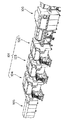
図3は電子部品実装装置を複数台直列に設置した電子部品実装ラインを示す平面図である。なお、本実施形態では一例として合計3台の電子部品実装装置を用いている。
前段の基板加工装置(図示せず)のライン下流側に接続された電子部品実装ライン60に、第1〜第3の電子部品実装装置61,70,80がこの順に設置されている。
第1の電子部品実装装置61のライン上流側には第1振り分けコンベヤ90が設置され、第3の電子部品実装装置80の下流側には第2振り分けコンベヤ92が設置されている。
第1〜第3の電子部品実装装置61,70,80は、第1実施形態の第1〜第3の電子部品実装装置10,30,40と各コンベヤの構成は同じであり、これらの部材に対しては同一の符号を付して説明を省略する。
【0043】
第1振り分けコンベヤ90には、この第1振り分けコンベヤ90を制御する第1振り分け制御回路91が接続され、コンセント91aを介して電源供給されている。
同様に、第2振り分けコンベヤ92には、この第2振り分けコンベヤ92を制御する第2振り分け制御回路93が接続され、コンセント93aを介して電源供給されている。
【0044】
第1の電子部品実装装置61には、未実装基板搬送コンベヤ23に接続した制御ケーブル62と、実装済み基板搬送コンベヤ24に接続した制御ケーブル63とがコンベヤに沿って内設され、それぞれの制御ケーブル62,63と同様に、他の制御ケーブル64も並設されている。また、制御ケーブル62,63及び他の制御ケーブル64には、それぞれの両端に接続端子が接続されている。
【0045】
また、第2の電子部品実装装置70、第3の電子部品実装装置80にも同様に、未実装基板搬送コンベヤ33,43に接続した制御ケーブル72,82が内設されると共に、実装済み基板搬送コンベヤ34,44に接続した制御ケーブル73,83が内設され、それぞれの制御ケーブル72,73,82,83と同様に他の制御ケーブル74,84が並設されている。また、制御ケーブル72,82,73,83及び他の制御ケーブル74,84は、それぞれの両端に接続端子が接続されている。
【0046】
図3に示すように、第1の電子部品実装装置61は、制御ケーブル62及び制御ケーブル63のライン上流側の接続端子が第1振り分け制御回路91に接続されることで、第1振り分け制御回路91により未実装基板搬送コンベヤ23及び実装済み基板搬送コンベヤ24を制御する。なお、制御ケーブル62及び制御ケーブル63のライン下流側の接続端子はいずれも接続されずに終端となっている。
【0047】
また、第2の電子部品実装装置70は、制御ケーブル72及び制御ケーブル73のライン下流側の接続端子がそれぞれ他の制御ケーブル84のライン上流側の接続端子に接続され、それぞれの制御ケーブル84のライン下流側の接続端子が第2振り分け制御回路93に接続されている。これにより、第2振り分け制御回路93が未実装基板搬送コンベヤ33及び実装済み基板搬送コンベヤ34を制御するようになる。なお、制御ケーブル72,73のライン上流側の接続端子はいずれも接続されずに終端となっている。
【0048】
そして、第3の電子部品実装装置80は、制御ケーブル82,制御ケーブル83のライン下流側の接続端子が第2振り分け制御回路93に接続されることにより、第2振り分け制御回路93が未実装基板搬送コンベヤ43及び実装済み基板搬送コンベヤ44を制御するようになる。なお、制御ケーブル82,83のライン上流側の接続端子はいずれも接続されずに終端となっている。
【0049】
以上の本実施形態の構成によれば、前述の第1実施形態に示した効果に加えて、電子部品実装装置を任意の複数台接続する構成としても、簡単に電子部品実装ラインを構築することができ、電子部品実装ラインのレイアウト変更等があった場合でも、ケーブル等を継ぎ足すことなく接続端子の接続作業によって簡単で迅速な組み立てが可能となる。
【0050】
即ち、第1〜第3の電子部品実装装置61,70,80では、制御ケーブル62,72,82や制御ケーブル63,73,83とは別に制御ケーブル64,74,84を内設することで、複数台の電子部品実装装置61,70,80を設置した際に、隣接する延長ケーブル64,74,84に制御ケーブル62,72,82や制御ケーブル63,73,83の端子を接続するだけで、各制御ケーブルを延長することができる。
【0051】
また、第1の電子部品実装装置61の未実装基板搬送コンベヤ23と実装済み基板搬送コンベヤ24は、第1振り分け制御回路91により電源供給されて制御されるため、仮に第1の電子部品実装装置61を電源オフとしても、未実装基板搬送コンベヤ23及び実装済み基板搬送コンベヤ24は電子部品実装ライン60で機能し続け、且つ、各コンベヤ23,24の電源ラインを第1の電子部品実装装置61とは別系統としているが、第1振り分け制御回路91から電源供給することで、運転準備作業等の作業負担を増加させない構成となる。この効果は第2、第3の電子部品実装装置70,80についても同様である。
【0052】
【発明の効果】
以上詳細に説明したように、本発明によれば、搬入位置から搬入した基板をバイパスさせて搬送するバイパスコンベヤを、電子部品実装装置とは別体の制御装置から制御することで、実装装置本体用の制御回路とバイパスコンベヤ用の制御回路が実質的に二重にならないように構成でき、設備コストを抑えると共に、装置の運転準備に余分な手間をなくすことができる。
【図面の簡単な説明】
【図1】本発明に係る本実施形態の電子部品実装装置の概略構成を示した斜視図である。
【図2】本発明に係る第1実施形態の電子部品実装装置を複数台直列に設置した電子部品実装ラインを示す平面図である。
【図3】本発明に係る第2実施形態の電子部品実装装置を複数台直列に設置した電子部品実装ラインを示す平面図である
【図4】従来の電子部品実装ラインを示す斜視図である。
【図5】従来の電子部品実装装置を複数台設置した状態を示す平面図である。
【符号の説明】
10,30,40,61,70,80 電子部品実装装置
16 基板
14 電子部品
21,31,41 実装コンベヤ
22,32,42,51,53,55,91,93 制御回路
23,33,43 未実装基板搬送コンベヤ(バイパスコンベヤ)
24,34,44 実装済み基板搬送コンベヤ(バイパスコンベヤ)
26,36,46 カバーガード
50,52,54,90,92 振り分けコンベヤ
62,72,82 バイパス制御ケーブル
63,73,83 搬出制御ケーブル
64,74,84 延長ケーブル
P1,P2 実装位置[0001]
BACKGROUND OF THE INVENTION
The present invention relates to a transport conveyor control method, an electronic component mounting apparatus, and an electronic component mounting line for an electronic component mounting apparatus that transports a substrate to a mounting position by a conveyor and mounts electronic components on the substrate at the mounting position.
[0002]
[Prior art]
An electronic component mounting apparatus is known as an apparatus for mounting electronic components on a printed circuit board (hereinafter referred to as “substrate”), and in recent years, it has been required to increase the production efficiency of the electronic component mounting apparatus. For this reason, in the electronic component mounting line, it is ideal that the mounting time per board is close to the processing time of the cream solder printing machine, the adhesive application device, etc. on the upstream side of the electronic component mounting line.
[0003]
Therefore, as shown in FIG. 4, a post-process of the
The board on which the electronic component mounting has been completed by each of the electronic
[0004]
The above mounting method will be described in more detail with reference to FIG. The first to third electronic
Further, a
[0005]
The operation of the
[0006]
Further, the first to third electronic
Further, a power supply outlet 107 a is connected to the
[0007]
According to the conventional electronic
[0008]
After the
The
[0009]
In addition, when the
Here, when the second electronic
[0010]
Then, after setting the
As described above, mounting efficiency is improved by assigning the
[0011]
[Problems to be solved by the invention]
By the way, when the production amount of the board is small, for example, the third electronic
[0012]
However, the unmounted
In addition, since the control circuit is provided in a separate system, the operator has to operate each control circuit, so that the operator is burdened, for example, it takes time to prepare for operation.
[0013]
SUMMARY OF THE INVENTION The present invention has been made in view of the above circumstances, and can operate a bypass conveyor provided in an electronic component mounting apparatus independently of the mounting apparatus main body, and a control circuit for the mounting apparatus main body and a control circuit for the conveyor. Provide a conveyor control method for an electronic component mounting apparatus, an electronic component mounting apparatus, and an electronic component mounting line that are configured so as not to be substantially doubled, thereby reducing equipment costs and extra labor for preparing the operation of the apparatus. The purpose is to eliminate.
[0014]
[Means for Solving the Problems]
In order to achieve the above object, the method for controlling a conveyor of an electronic component mounting apparatus according to the present invention conveys a substrate carried from a loading position to the mounting position when there is no board at the mounting position of the electronic component mounting apparatus. While mounting electronic components Said An electronic component mounting apparatus for transporting a board carried from the carry-in position to the carry-out position by bypassing the mounting position when there is a board at the mounting position of the electronic component mounting apparatus Electronic component mounting line with multiple units arranged in series A transport conveyor control method, The power supply of the bypass conveyor that bypasses and conveys the board is performed separately from the power supply of the electronic component mounting apparatus, and when any electronic component mounting apparatus is stopped, the electronic component mounting apparatus is stopped. The power supply to the bypass conveyor is continued to be turned off. It is characterized by that.
[0015]
In the transport conveyor control method of this electronic component mounting apparatus, when an electronic component is mounted on the substrate at the mounting position, when another substrate is loaded from the loading position, Without mounting, the mounting position is bypassed and unloaded to the unloading position. At that time, by controlling the bypass conveyor that bypasses and conveys the board carried from the carry-in position from a control device separate from the electronic component mounting device, a control circuit for the mounting device body and a control circuit for the bypass conveyor Can be configured so as not to be substantially doubled, thereby reducing the equipment cost and eliminating the need for extra preparation for operating the apparatus.
Moreover, in the transport conveyor control method of this electronic component mounting apparatus, The power supply of the bypass conveyor that bypasses and conveys the board is performed separately from the power supply of the electronic component mounting apparatus, and when any electronic component mounting apparatus is stopped, the electronic component mounting apparatus is stopped. The power supply to the bypass conveyor is continued to be turned off. This makes it possible to operate the bypass conveyor independently even when the power supply to the electronic component mounting apparatus is stopped. Even when only the bypass conveyor needs to be operated, it is necessary to supply power to the entire electronic component mounting apparatus. Therefore, power consumption can be reduced.
[0016]
The method for controlling a conveyor of an electronic component mounting apparatus according to claim 2 comprises: To reduce production volume, turn off the power of any electronic component mounting device, and The power supply to the bypass conveyor of the mounting apparatus is continued.
[0018]
Claim 3 Conveyor control method for electronic component mounting line Is When maintenance work is performed on any of the electronic component mounting apparatuses, the power supply of the electronic component mounting apparatus that performs the maintenance work is turned off, and the power supply to the bypass conveyor of the electronic component mounting apparatus is continued. It is characterized by that.
[0020]
Claim 4 Electronic component mounting line The mounting conveyor that transports the board from the board loading position to the mounting position for mounting electronic components and the bypass conveyor that bypasses the mounting position from the board loading position and transports the board to the board unloading position are integrated. Electronic component mounting apparatus provided Electronic component mounting line with multiple units arranged in series Because The power supply of the bypass conveyor that bypasses and conveys the board is performed separately from the power supply of the electronic component mounting device, and when any electronic component mounting device is stopped, the electronic component mounting device is stopped. The power supply to the bypass conveyor is continued to be turned off. It is characterized by that.
[0021]
This electronic component mounting line Then, by providing a control device for controlling the bypass conveyor in another device separate from the electronic component mounting device, the control circuit for the mounting device main body and the control circuit for each conveyor do not substantially double. It is possible to reduce the cost of equipment and to eliminate the trouble of preparing the apparatus for operation.
Also, this Electronic component mounting line Then, by providing the power supply line for the bypass conveyor in a separate system from the power supply line for the electronic component mounting apparatus, the bypass conveyor can be operated independently even if the power supply to the electronic component mounting apparatus is stopped. Even when only the bypass conveyor needs to be operated, it is not necessary to supply power to the entire electronic component mounting apparatus, so that power consumption can be reduced.
[0022]
Claim 5 Electronic component mounting line Is provided with a cover guard that covers the bypass conveyor.
[0023]
this Electronic component mounting line Then, by providing a cover guard that covers the bypass conveyor, even when performing maintenance work on the electronic component mounting device, the bypass conveyor is protected by the cover guard, and the bypass conveyor can be operated without hindering the maintenance work. The maintenance work can be performed smoothly and the safety of the work can be improved.
[0024]
Claim 6 Electronic component mounting line Are characterized in that the bypass conveyor is a mounted substrate transfer conveyor that transfers a substrate on which electronic components are mounted and an unmounted substrate transfer conveyor that transfers an unmounted substrate.
[0025]
this Electronic component mounting line Then, when a board is carried in during mounting of an electronic component, this board is carried out by an unmounted board transfer conveyor, and when a mounted board is carried in, this mounted board is transferred to a mounted board. Unload by conveyor.
[0028]
DETAILED DESCRIPTION OF THE INVENTION
DESCRIPTION OF EXEMPLARY EMBODIMENTS Hereinafter, preferred embodiments of a method for controlling a conveyor of an electronic component mounting apparatus, an electronic component mounting apparatus and an electronic component mounting line according to the present invention will be described in detail with reference to the drawings.
In each embodiment described below, the same members described in FIG. 5 are denoted by the same reference numerals, and the description thereof is omitted.
[0029]
FIG. 1 is a perspective view showing a schematic configuration of the electronic component mounting apparatus according to the present embodiment.
The electronic
[0030]
When the
Next, the
[0031]
FIG. 2 shows an electronic component mounting line in which electronic
As shown in FIG. 2, the first to third electronic
A
[0032]
A first
Similarly, a second
[0033]
In the first electronic
The unmounted
[0034]
Similarly, the second electronic
Similarly, the third electronic
The unmounted
[0035]
According to the electronic
First, the
Here, when the first electronic
[0036]
After the
The board |
[0037]
In addition, when the first electronic
[0038]
Here, when the second electronic
[0039]
After the
[0040]
In this way, by mounting the electronic component by allocating the
Furthermore, in order to reduce the production amount, any one of the first to third electronic
[0041]
In addition, the first to third electronic
[0042]
Next, a second embodiment of the electronic component mounting apparatus will be described.
FIG. 3 is a plan view showing an electronic component mounting line in which a plurality of electronic component mounting apparatuses are installed in series. In the present embodiment, a total of three electronic component mounting apparatuses are used as an example.
First to third electronic
A
The first to third electronic
[0043]
A first
Similarly, a second
[0044]
In the first electronic
[0045]
Similarly, the second electronic
[0046]
As shown in FIG. 3, the first electronic
[0047]
In the second electronic
[0048]
In the third electronic
[0049]
According to the configuration of the present embodiment described above, in addition to the effects shown in the first embodiment, it is possible to easily construct an electronic component mounting line even when a plurality of electronic component mounting apparatuses are connected. Even when the layout of the electronic component mounting line is changed, it is possible to easily and quickly assemble by connecting the connection terminals without adding cables or the like.
[0050]
That is, in the first to third electronic
[0051]
In addition, since the unmounted
[0052]
【The invention's effect】
As described above in detail, according to the present invention, the bypass conveyor for bypassing and transporting the board carried from the carry-in position is controlled by a control device separate from the electronic component mounting device, so that the mounting device body Thus, the control circuit for the bypass conveyor and the control circuit for the bypass conveyor can be configured so as not to be substantially doubled, so that the equipment cost can be reduced, and an extra effort can be eliminated in preparing the operation of the apparatus.
[Brief description of the drawings]
FIG. 1 is a perspective view showing a schematic configuration of an electronic component mounting apparatus according to an embodiment of the present invention.
FIG. 2 is a plan view showing an electronic component mounting line in which a plurality of electronic component mounting apparatuses according to the first embodiment of the present invention are installed in series.
FIG. 3 is a plan view showing an electronic component mounting line in which a plurality of electronic component mounting apparatuses according to a second embodiment of the present invention are installed in series.
FIG. 4 is a perspective view showing a conventional electronic component mounting line.
FIG. 5 is a plan view showing a state in which a plurality of conventional electronic component mounting apparatuses are installed.
[Explanation of symbols]
10, 30, 40, 61, 70, 80 Electronic component mounting apparatus
16 substrates
14 Electronic components
21, 31, 41 Mounting conveyor
22, 32, 42, 51, 53, 55, 91, 93 Control circuit
23, 33, 43 Unmounted substrate transfer conveyor (bypass conveyor)
24, 34, 44 Mounted circuit board conveyor (bypass conveyor)
26, 36, 46 Cover guard
50, 52, 54, 90, 92 Sorting conveyor
62, 72, 82 Bypass control cable
63, 73, 83 Unloading control cable
64, 74, 84 Extension cable
P1, P2 mounting position
Claims (6)
前記基板をバイパスさせて搬送するバイパスコンベアの電源供給を、前記電子部品実装装置の電源供給とは別系統で行い、
いずれかの電子部品実装装置を停止させる場合には、停止させる電子部品実装装置の電源をオフし、前記バイパスコンベアへの電源供給を継続させる
ことを特徴とする電子部品実装ラインの搬送コンベア制御方法。When there is no board at the mounting position of the electronic component mounting apparatus, the board loaded from the carry-in position is transported to the mounting position to mount the electronic component on the board, while when the board is at the mounting position of the electronic component mounting apparatus A transport conveyor control method for an electronic component mounting line in which a plurality of electronic component mounting devices for bypassing the mounting position and transporting the substrate loaded from the loading position to the unloading position are arranged in series ,
Power supply of a bypass conveyor that bypasses and conveys the substrate is performed separately from the power supply of the electronic component mounting apparatus,
When stopping any one of the electronic component mounting apparatuses, the power supply of the electronic component mounting apparatus to be stopped is turned off, and the power supply to the bypass conveyor is continued. .
前記基板をバイパスさせて搬送するバイパスコンベアの電源供給を、前記電子部品実装装置の電源供給とは別系統で行い、
いずれかの電子部品実装装置を停止させる場合には、停止させる電子部品実装装置の電源をオフし、前記バイパスコンベアへの電源供給を継続させる
ことを特徴とする電子部品実装ライン。A mounting conveyor that transports the substrate from the board loading position to a mounting position for mounting electronic components, and a bypass conveyor that bypasses the mounting position from the board loading position and transports the board to the board unloading position are provided integrally. An electronic component mounting line in which a plurality of electronic component mounting devices are arranged in series ,
Power supply of a bypass conveyor that bypasses and conveys the substrate is performed separately from the power supply of the electronic component mounting apparatus,
An electronic component mounting line , wherein when stopping any of the electronic component mounting apparatuses, the power of the electronic component mounting apparatus to be stopped is turned off and the power supply to the bypass conveyor is continued .
Priority Applications (1)
| Application Number | Priority Date | Filing Date | Title |
|---|---|---|---|
| JP2001322573A JP3958552B2 (en) | 2001-10-19 | 2001-10-19 | Conveying conveyor control method for electronic component mounting apparatus, electronic component mounting apparatus, and electronic component mounting line |
Applications Claiming Priority (1)
| Application Number | Priority Date | Filing Date | Title |
|---|---|---|---|
| JP2001322573A JP3958552B2 (en) | 2001-10-19 | 2001-10-19 | Conveying conveyor control method for electronic component mounting apparatus, electronic component mounting apparatus, and electronic component mounting line |
Publications (2)
| Publication Number | Publication Date |
|---|---|
| JP2003133789A JP2003133789A (en) | 2003-05-09 |
| JP3958552B2 true JP3958552B2 (en) | 2007-08-15 |
Family
ID=19139600
Family Applications (1)
| Application Number | Title | Priority Date | Filing Date |
|---|---|---|---|
| JP2001322573A Expired - Fee Related JP3958552B2 (en) | 2001-10-19 | 2001-10-19 | Conveying conveyor control method for electronic component mounting apparatus, electronic component mounting apparatus, and electronic component mounting line |
Country Status (1)
| Country | Link |
|---|---|
| JP (1) | JP3958552B2 (en) |
Families Citing this family (3)
| Publication number | Priority date | Publication date | Assignee | Title |
|---|---|---|---|---|
| JP2014068040A (en) * | 2014-01-14 | 2014-04-17 | Panasonic Corp | Electronic component mounting line and electronic component mounting method |
| WO2017130341A1 (en) * | 2016-01-28 | 2017-08-03 | 富士機械製造株式会社 | Power management system for production line |
| JP7134893B2 (en) * | 2019-02-01 | 2022-09-12 | ヤマハ発動機株式会社 | Substrate processing system and substrate processing method |
-
2001
- 2001-10-19 JP JP2001322573A patent/JP3958552B2/en not_active Expired - Fee Related
Also Published As
| Publication number | Publication date |
|---|---|
| JP2003133789A (en) | 2003-05-09 |
Similar Documents
| Publication | Publication Date | Title |
|---|---|---|
| US7032304B2 (en) | Method for conveying printed circuit boards | |
| JP4746148B2 (en) | Anti-substrate operation system and anti-substrate operation unit for constructing the same | |
| JPH11260883A (en) | Substrate processing equipment | |
| JP4278903B2 (en) | Electronic component mounting apparatus and electronic component mounting method | |
| JP4346849B2 (en) | Electronic component mounting apparatus and electronic component mounting method | |
| JP3958552B2 (en) | Conveying conveyor control method for electronic component mounting apparatus, electronic component mounting apparatus, and electronic component mounting line | |
| JP3771214B2 (en) | Electronic component mounting method | |
| JPH09505946A (en) | Method and apparatus for automatically mounting SMD components on upper and lower surfaces of a printed circuit board | |
| JP3652023B2 (en) | Electronic component mounting equipment | |
| JP2005531921A (en) | Mounting system and method for mounting components on a substrate | |
| JP2002208797A (en) | Board transfer method for component mounting equipment | |
| JP4644941B2 (en) | Electronic component mounting equipment | |
| JP4298202B2 (en) | Electronic component mounting apparatus and electronic component mounting method | |
| JP3923134B2 (en) | Component mounting method | |
| JP2002246793A (en) | Electronic component mounting apparatus and electronic component mounting method | |
| JP2003142882A (en) | Board transfer device and board transfer method in electronic component mounting line | |
| JP3245568B2 (en) | Soldering equipment | |
| JP2002246794A (en) | Electronic component mounting machine | |
| JP3117821B2 (en) | Printed circuit board mounting machine | |
| JP4134662B2 (en) | Electronic component mounting line and board conveying method in electronic component mounting line | |
| JP3652242B2 (en) | Substrate transport method in electronic component mounting apparatus | |
| JP2002026577A (en) | Component mounting method and equipment | |
| WO2023203610A1 (en) | Substrate production system | |
| JP3341764B2 (en) | Electronic component mounting method | |
| JPH0542459A (en) | Pallet carrying system |
Legal Events
| Date | Code | Title | Description |
|---|---|---|---|
| A621 | Written request for application examination |
Free format text: JAPANESE INTERMEDIATE CODE: A621 Effective date: 20040915 |
|
| RD04 | Notification of resignation of power of attorney |
Free format text: JAPANESE INTERMEDIATE CODE: A7424 Effective date: 20060324 |
|
| A131 | Notification of reasons for refusal |
Free format text: JAPANESE INTERMEDIATE CODE: A131 Effective date: 20070117 |
|
| A521 | Written amendment |
Free format text: JAPANESE INTERMEDIATE CODE: A523 Effective date: 20070316 |
|
| TRDD | Decision of grant or rejection written | ||
| A01 | Written decision to grant a patent or to grant a registration (utility model) |
Free format text: JAPANESE INTERMEDIATE CODE: A01 Effective date: 20070411 |
|
| A61 | First payment of annual fees (during grant procedure) |
Free format text: JAPANESE INTERMEDIATE CODE: A61 Effective date: 20070510 |
|
| R150 | Certificate of patent (=grant) or registration of utility model |
Free format text: JAPANESE INTERMEDIATE CODE: R150 |
|
| FPAY | Renewal fee payment (prs date is renewal date of database) |
Free format text: PAYMENT UNTIL: 20110518 Year of fee payment: 4 |
|
| FPAY | Renewal fee payment (prs date is renewal date of database) |
Free format text: PAYMENT UNTIL: 20110518 Year of fee payment: 4 |
|
| FPAY | Renewal fee payment (prs date is renewal date of database) |
Free format text: PAYMENT UNTIL: 20120518 Year of fee payment: 5 |
|
| FPAY | Renewal fee payment (prs date is renewal date of database) |
Free format text: PAYMENT UNTIL: 20120518 Year of fee payment: 5 |
|
| FPAY | Renewal fee payment (prs date is renewal date of database) |
Free format text: PAYMENT UNTIL: 20130518 Year of fee payment: 6 |
|
| FPAY | Renewal fee payment (prs date is renewal date of database) |
Free format text: PAYMENT UNTIL: 20130518 Year of fee payment: 6 |
|
| LAPS | Cancellation because of no payment of annual fees |