JP3955285B2 - Inverter control device for motor drive and air conditioner - Google Patents
Inverter control device for motor drive and air conditioner Download PDFInfo
- Publication number
- JP3955285B2 JP3955285B2 JP2004054287A JP2004054287A JP3955285B2 JP 3955285 B2 JP3955285 B2 JP 3955285B2 JP 2004054287 A JP2004054287 A JP 2004054287A JP 2004054287 A JP2004054287 A JP 2004054287A JP 3955285 B2 JP3955285 B2 JP 3955285B2
- Authority
- JP
- Japan
- Prior art keywords
- voltage
- inverter
- motor
- value
- frequency
- Prior art date
- Legal status (The legal status is an assumption and is not a legal conclusion. Google has not performed a legal analysis and makes no representation as to the accuracy of the status listed.)
- Expired - Fee Related
Links
Images


Classifications
-
- H—ELECTRICITY
- H02—GENERATION; CONVERSION OR DISTRIBUTION OF ELECTRIC POWER
- H02P—CONTROL OR REGULATION OF ELECTRIC MOTORS, ELECTRIC GENERATORS OR DYNAMO-ELECTRIC CONVERTERS; CONTROLLING TRANSFORMERS, REACTORS OR CHOKE COILS
- H02P27/00—Arrangements or methods for the control of AC motors characterised by the kind of supply voltage
- H02P27/04—Arrangements or methods for the control of AC motors characterised by the kind of supply voltage using variable-frequency supply voltage, e.g. inverter or converter supply voltage
- H02P27/045—Arrangements or methods for the control of AC motors characterised by the kind of supply voltage using variable-frequency supply voltage, e.g. inverter or converter supply voltage whereby the speed is regulated by measuring the motor speed and comparing it with a given physical value
Landscapes
- Engineering & Computer Science (AREA)
- Power Engineering (AREA)
- Control Of Ac Motors In General (AREA)
Description
本発明はモータ駆動用のインバータ制御装置および空気調和機に関する。 The present invention relates to an inverter control device for driving a motor and an air conditioner.
汎用インバータなどで用いられている一般的なインダクションモータ駆動用インバータ制御装置として、図18に示すようなV/F制御方式のインダクションモータ駆動用インバータ制御装置がよく知られている(例えば、非特許文献1の第661〜711頁参照)。 As a general induction motor drive inverter control device used in a general-purpose inverter or the like, a V / F control type induction motor drive inverter control device as shown in FIG. 18 is well known (for example, non-patent). (Refer to pages 661 to 711 of Document 1).
図18において、主回路は直流電源装置113と、インバータ3とインダクションモータ4とから構成されており、直流電源装置113については、交流電源1と、整流回路2と、インバータ3の直流電圧源のために電気エネルギを蓄積する平滑コンデンサ112と、交流電源1の力率改善用リアクタ111から構成されている。
In FIG. 18, the main circuit is composed of a DC
一方、制御回路では、外部から与えられたインダクションモータ4の速度指令W*に基づいてインダクションモータ4に印加するモータ電圧値を決定するV/F制御パターン部13と、V/F制御パターン部13から決定されるモータ電圧値に基づいてインダクションモータ4の各相電圧指令値を作成するモータ電圧指令作成部14と、モータ電圧指令作成部14から作成された各相電圧指令値に基づいてインバータ3のPWM信号を生成するPWM制御部18から構成されている。
On the other hand, in the control circuit, a V / F
なお、一般的なV/F制御パターン部13の一例を図19に示す。
An example of a general V / F
図19に示すように速度指令W*に対してインダクションモータ4に印加するモータ電圧値が一義的に決定するような構成となっている。一般的には、速度指令W*とモータ電圧値の値をテーブル値としてマイコン等の演算装置のメモリに記憶させ、テーブル値以外の速度指令W*に対してはテーブル値から線形補間することでモータ電圧値を導出している。
As shown in FIG. 19, the motor voltage value applied to the
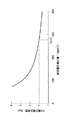
ここで、交流電源1が220V(交流電源周波数50Hz)、インバータ3の入力が1.5kW、平滑コンデンサ112が1500μFのとき、力率改善用リアクタ111が5mHおよび20mHの場合における交流電源電流の高調波成分と交流電源周波数に対する次数との関係を図20に示す。図20はIEC(国際電気標準会議)規格と併せて示したもので、力率改善用リアクタ111が5mHの場合には特に第3高調波成分がIEC規格のそれを大きく上回っているが、20mHの場合には40次までの高調波成分においてIEC規格をクリアしていることがわかる。
Here, when the
そのため特に高負荷時においてもIEC規格をクリアするためには力率改善用リアクタ111のインダクタンス値をさらに大きくするなどの対策を取る必要があり、インバータ装置の大型化や重量増加、さらにはコストUPを招くという不都合があった。
For this reason, it is necessary to take measures such as further increasing the inductance value of the power
そこで、力率改善用リアクタ111のインダクタンス値の増加を抑え、電源高調波成分の低減と高力率化を達成する直流電源装置として、例えば図21に示すような直流電源装置が提案されている(例えば、特許文献1参照)。
Therefore, for example, a DC power supply device as shown in FIG. 21 has been proposed as a DC power supply device that suppresses an increase in the inductance value of the power
図21において、交流電源1の交流電源電圧を、ダイオードD1〜D4をブリッジ接続してなる全波整流回路の交流入力端子に印加し、その出力を、リアクトルLinを介して中間コンデンサCに充電し、この中間コンデンサCの電荷を平滑コンデンサCDに放電して、負荷抵抗RLに直流電圧を供給する。この場合、リアクトルLinの負荷側、及び中間コンデンサCを接続する正負の直流電流経路にトランジスタQ1を接続し、このトランジスタQ1をベース駆動回路G1で駆動する構成となっている。
In FIG. 21, the AC power supply voltage of the
また、直流電源装置は、ベース駆動回路G1にパルス電圧を印加するパルス発生回路I1、I2と、ダミー抵抗Rdmとをさらに備えている。パルス発生回路I1、I2は、それぞれ交流電源電圧のゼロクロス点を検出する回路と、ゼロクロス点の検出から交流電源電圧の瞬時値が中間コンデンサCの両端電圧と等しくなるまでダミー抵抗Rdmにパルス電流を流すパルス電流回路とで構成されている。 The DC power supply device further includes pulse generation circuits I1 and I2 that apply a pulse voltage to the base drive circuit G1, and a dummy resistor Rdm. Each of the pulse generation circuits I1 and I2 detects a zero cross point of the AC power supply voltage, and applies a pulse current to the dummy resistor Rdm until the instantaneous value of the AC power supply voltage becomes equal to the voltage across the intermediate capacitor C from the detection of the zero cross point. It consists of a pulse current circuit to flow.
ここで、パルス発生回路I1は交流電源電圧の半サイクルの前半にてパルス電圧を発生させ、パルス発生I2は交流電源電圧の半サイクルの後半にてパルス電圧を発生させる。 Here, the pulse generation circuit I1 generates a pulse voltage in the first half of the half cycle of the AC power supply voltage, and the pulse generation I2 generates a pulse voltage in the second half of the half cycle of the AC power supply voltage.
なお、トランジスタQ1をオン状態にしてリアクトルLinに強制的に電流を流す場合、中間コンデンサCの電荷がトランジスタQ1を通して放電することのないように逆流防止用ダイオードD5が接続され、さらに、中間コンデンサCの電荷を平滑コンデンサCDに放電する経路に、逆流防止用ダイオードD6と、平滑効果を高めるリアクトルLdcが直列に接続されている。 When the transistor Q1 is turned on and a current is forced to flow through the reactor Lin, a backflow prevention diode D5 is connected so that the charge of the intermediate capacitor C is not discharged through the transistor Q1, and further, the intermediate capacitor C A reverse current prevention diode D6 and a reactor Ldc that enhances the smoothing effect are connected in series to the path for discharging the electric charge of the current to the smoothing capacitor CD.
上記の構成において、交流電源電圧の瞬時値が中間コンデンサCの両端電圧を超えない位相区間の一部または全部においてトランジスタQ1をオン状態にすることによって、装置の大型化を抑えたままで、高調波成分の低減と高力率化を達成することができる。 In the above configuration, by turning on the transistor Q1 in part or all of the phase interval in which the instantaneous value of the AC power supply voltage does not exceed the voltage across the intermediate capacitor C, the harmonics can be maintained while suppressing the increase in size of the device. Component reduction and higher power factor can be achieved.
しかしながら、上記従来の構成では、容量の大きな平滑用コンデンサCDとリアクトルLin(特許文献1では1500μF、6.2mH時のシミュレーション結果について記載されている)とを依然として有したままであり、さらに中間コンデンサCとトランジスタQ1とベース駆動回路G1とパルス発生回路I1、I2とダミー抵抗Rdmと逆流防止用ダイオードD5、D6と平滑効果を高めるリアクトルLdcとを具備する必要があり、このため、装置の大型化や部品点数の増加に伴なうコスト増を招くという課題を有していた。 However, the above-described conventional configuration still has the smoothing capacitor CD having a large capacity and the reactor Lin (described in the simulation result at 1500 μF and 6.2 mH in Patent Document 1), and further the intermediate capacitor. C, transistor Q1, base drive circuit G1, pulse generation circuits I1 and I2, dummy resistor Rdm, backflow prevention diodes D5 and D6, and a reactor Ldc that increases the smoothing effect must be provided. In addition, there is a problem that the cost increases with the increase in the number of parts.
本発明はこのような従来の課題を解決するものであり、小型・軽量・低コストのモータ駆動用インバータ制御装置を提供することを目的とする。 The present invention solves such a conventional problem, and an object of the present invention is to provide a motor drive inverter control device that is small, light, and low in cost.
本発明に係るインバータ制御装置は、交流電源からの交流電力を直流電力に変換する整流回路と、その整流回路からの直流電力を所望の周波数、電圧を持つ交流電力に変換しモータに供給するインバータを含む。整流回路はダイオードブリッジと、ダイオードブリッジの交流入力側または直流出力側に接続される所定の小容量のリアクタで構成される。インバータの直流母線間には、モータの回生エネルギを吸収するための所定の小容量のコンデンサが設けられる。インバータ制御装置は、外部から与えられるモータの速度指令値に基づき、モータの各相電圧指令値を作成するモータ電圧指令作成手段と、インバータの直流電圧値を検出し直流電圧検出値として出力するPN電圧検出手段と、インバータの直流電圧基準値を決定する直流電圧基準値演算手段と、PN電圧補正手段と、モータ電圧指令補正手段とを備える。PN電圧補正手段は、直流電圧基準値を直流電圧検出値で除算することによりPN電圧補正係数を導出し、直流電圧検出値が直流電圧基準値以上の場合において使用されるモードであってPN電圧補正係数に1を設定する第1のモードと、直流電圧基準値を直流電圧検出値で除算することにより得られた結果をそのまま設定する第2のモードとを有する。モータ電圧指令補正手段は、モータ電圧指令作成手段から得られる各相電圧指令値と、PN電圧補正手段の出力値であるPN電圧補正係数とを乗算することにより各相電圧指令値の補正を行なう。 An inverter control device according to the present invention includes a rectifier circuit that converts AC power from an AC power source into DC power, and an inverter that converts DC power from the rectifier circuit into AC power having a desired frequency and voltage and supplies the AC power to a motor. including. The rectifier circuit includes a diode bridge and a predetermined small capacity reactor connected to the AC input side or DC output side of the diode bridge. A predetermined small-capacitance capacitor for absorbing the regenerative energy of the motor is provided between the DC buses of the inverter. The inverter control device includes motor voltage command generating means for generating each phase voltage command value of the motor based on the motor speed command value given from the outside, and a PN that detects the DC voltage value of the inverter and outputs it as a DC voltage detection value A voltage detection unit; a DC voltage reference value calculation unit that determines a DC voltage reference value of the inverter; a PN voltage correction unit; and a motor voltage command correction unit. The PN voltage correction means derives a PN voltage correction coefficient by dividing the DC voltage reference value by the DC voltage detection value, and is a mode used when the DC voltage detection value is greater than or equal to the DC voltage reference value. There are a first mode in which 1 is set for the correction coefficient and a second mode in which the result obtained by dividing the DC voltage reference value by the DC voltage detection value is set as it is. The motor voltage command correction means corrects each phase voltage command value by multiplying each phase voltage command value obtained from the motor voltage command creation means by a PN voltage correction coefficient that is an output value of the PN voltage correction means. .
上記の構成によって、小容量コンデンサおよび小容量リアクタを用いることで小型・軽量・低コストのインダクションモータ駆動用インバータ制御装置を実現でき、インバータ直流電圧が大幅に変動してモータの駆動が困難あるいは不可能となる場合でも、モータに印加する電圧がほぼ一定となるようにインバータを動作させ、モータの駆動を維持することが可能であり、さらに交流電源電流の変動を抑制し、交流電源力率の改善と交流電源電流の高調波成分を抑制することが可能となる。 With the above configuration, a small, lightweight, and low cost induction motor drive inverter control device can be realized by using a small-capacitor and a small-capacity reactor, and the inverter DC voltage fluctuates greatly, making it difficult or impossible to drive the motor. Even when possible, it is possible to operate the inverter so that the voltage applied to the motor is almost constant and maintain the drive of the motor. It becomes possible to improve and suppress the harmonic component of the AC power supply current.
また、直流電圧基準値演算手段で決定される直流電圧基準値は、外部から与えられるモータの速度指令値に応じて可変としてもよい。この構成によって、更なる交流電源電流の高調波成分抑制を図ることが可能となる。 Further, the DC voltage reference value determined by the DC voltage reference value calculation means may be variable according to the motor speed command value given from the outside. With this configuration, it is possible to further suppress harmonic components of the AC power supply current.
また、交流電源周波数の偶数倍の周波数を持つ共振周波数を中心としてその前後に所定の周波数幅を持たせた周波数範囲内でインバータ運転周波数が定常的に固定されるのを回避するよう、インバータ運転周波数を制御してもよい。この構成によって、インバータ周波数と交流電源周波数との共振現象を回避することでモータの不安定動作を防止し、安定した駆動を実現することが可能となる。 In addition, the inverter operation is avoided so that the inverter operation frequency is fixed constantly within a frequency range having a predetermined frequency width around the resonance frequency having an even multiple of the AC power supply frequency. The frequency may be controlled. With this configuration, the unstable phenomenon of the motor can be prevented by avoiding the resonance phenomenon between the inverter frequency and the AC power supply frequency, and stable driving can be realized.
また、小容量リアクタと小容量コンデンサとで定まる共振周波数を、交流電源周波数の40倍よりも大きくなるように小容量リアクタおよび小容量コンデンサの組み合わせを決定するものである。上記の構成によって、交流電源電流の高調波成分を抑制し、IEC規格をクリアすることが可能である。 In addition, the combination of the small-capacity reactor and the small-capacitance capacitor is determined so that the resonance frequency determined by the small-capacity reactor and the small-capacitance capacitor is larger than 40 times the AC power supply frequency. With the above configuration, it is possible to suppress the harmonic component of the AC power supply current and clear the IEC standard.
また、インバータが停止した際に上昇する直流電圧検出値の最大値が素子の耐圧よりも小さくなるように小容量コンデンサの容量を決定してもよい。インバータ直流電圧の最大値を各駆動素子の耐圧よりも小さくなるように小容量コンデンサの容量を決定することで周辺回路の破壊を防止することが可能となる。 Further, the capacitance of the small-capacitance capacitor may be determined so that the maximum value of the detected DC voltage that increases when the inverter is stopped is smaller than the withstand voltage of the element. By determining the capacitance of the small-capacitance capacitor so that the maximum value of the inverter DC voltage is smaller than the withstand voltage of each driving element, it is possible to prevent the peripheral circuit from being destroyed.
また、予め設定された交流電源力率値を満足するようにインバータのキャリア周波数を決定してもよい。この構成によって、予め設定された交流電源力率値を満足することが可能となり、必要最小限のキャリア周波数を設定することにより、インバータ損失を必要最小限に抑制することが可能となる。 Further, the carrier frequency of the inverter may be determined so as to satisfy a preset AC power source power factor value. With this configuration, it is possible to satisfy a preset AC power source power factor value, and it is possible to suppress the inverter loss to the minimum necessary by setting the minimum necessary carrier frequency.
本発明によれば、各相電圧指令値を好適に補正するため、小容量コンデンサおよび小容量リアクタの使用が可能となる。これにより、小型・軽量・低コストのモータ駆動用インバータ制御装置を実現でき、インバータ直流電圧が大幅に変動してモータの駆動が困難あるいは不可能となる場合でも、モータに印加する電圧がほぼ一定となるようにインバータを動作させながら、モータのより安定した駆動の維持を図る運転領域と、交流電源電流の変動を抑制し、交流電源力率の改善と交流電源電流の高調波成分の特に3次成分を抑制する運転領域との選択が可能となる。
According to the present invention, it is possible to use a small-capacity capacitor and a small-capacity reactor in order to suitably correct each phase voltage command value. As a result, a small, light, and low-cost inverter control device for driving a motor can be realized, and the voltage applied to the motor is almost constant even when the inverter DC voltage fluctuates and driving the motor becomes difficult or impossible. An operating region for maintaining a more stable drive of the motor while operating the inverter to suppress the fluctuation of the AC power supply current, improving the AC power supply power factor and especially the harmonic component of the AC
以下本発明の実施の形態について図面を参照しながら説明する。 Embodiments of the present invention will be described below with reference to the drawings.
(実施の形態1)
本発明の第1の実施形態を示すインダクションモータ駆動用インバータ制御装置のシステム構成図を図1に示す。図1において、インバータ制御装置の主回路は交流電源1と、交流電力を直流電力に変換するダイオードブリッジ2と、2mH以下の小容量リアクタ11と、100μF以下の小容量コンデンサ12と、直流電力を交流電力に変換するインバータ3と、インバータ3により変換された交流電力により駆動するインダクションモータ4から構成されている。
(Embodiment 1)
FIG. 1 shows a system configuration diagram of an induction motor driving inverter control apparatus showing a first embodiment of the present invention. In FIG. 1, the main circuit of the inverter control device includes an
一方、インバータ制御装置の制御回路は、V/F制御パターン部13と、モータ電圧指令作成部14と、PN電圧検出部15と、PN電圧補正部16と、モータ電圧指令補正部17と、PWM制御部18と、直流電圧基準値演算部19とを含む。
On the other hand, the control circuit of the inverter control device includes a V / F
V/F制御パターン部13は、外部から与えられたインダクションモータ4の速度指令W*に基づいてインダクションモータ4に印加するモータ電圧値を決定する。モータ電圧作成部14は、V/F制御パターン部13から決定されるモータ電圧値に基づいてインダクションモータ4の各相電圧指令値を作成する。PN電圧検出部15は、インバータ3の直流電圧値を検出する。直流電圧基準値演算部19はインバータ3の直流電圧基準値を決定する。PN電圧補正部16は、直流電圧基準値演算部19で決定されたインバータ3の直流電圧基準値と、PN電圧検出部15から得られるインバータ3の直流電圧検出値とを比較し、その比較結果からPN電圧補正係数を導出する。モータ電圧指令補正部17は、モータ電圧指令作成部14から得られる各相電圧指令値とPN電圧補正部16の出力値であるPN電圧補正係数とを乗算することにより各相電圧指令値の電圧補正を行ない、インダクションモータ4のモータ電圧指令補正値を作成する。PWM制御部18は、モータ電圧指令補正部17から作成されたモータ電圧指令補正値に基づいてインバータ3のPWM信号を生成する。
The V / F
なお、V/F制御パターン部13については、上述の従来の技術にて説明しているのでここでは説明を省略する。(図18のV/F制御方式のインダクションモータ駆動用インバータ制御装置)
以下、本実施形態のインバータ制御装置の具体的な動作について説明する。
Since the V / F
Hereinafter, a specific operation of the inverter control device of the present embodiment will be described.
モータ電圧指令作成部14は、式(1)で表される演算により各相電圧指令値vu *、vv *、vw *を作成する。
The motor voltage

ここで、VmはV/F制御パターン部13から決定されるモータ電圧値であり、θ1は式(2)で表されるように速度指令W*を時間積分することで導出する。
Here, V m is a motor voltage value determined from the V / F
![]()
![]()
PN電圧補正部16は2つの動作モードを有する。図2はPN電圧補正部16の第1のモードを示した図である。PN電圧補正部16は直流電圧基準値演算部19で決定されたインバータ3の直流電圧基準値Vpn0と、PN電圧検出部15から得られるインバータ3の直流電圧検出値vpnとを用いて式(3)のようにPN電圧補正係数kpnを導出する。
The PN
ここで、kpn_maxは予め設定されたPN電圧補正係数の最大値である。 Here, k pn — max is a maximum value of a preset PN voltage correction coefficient.
また、図3はPN電圧補正部16の第2のモードを示した図で、式(4)のようにPN電圧補正係数kpnを導出する。
FIG. 3 is a diagram showing a second mode of the PN
また、モータ電圧指令補正部17では各相電圧指令値vu *、vv *、vw *とPN電圧補正係数kpnを用いて式(5)のようにモータ電圧指令補正値vuh *、vvh *、vwh *を導出する。 Further, the motor voltage command correction unit 17 uses the respective phase voltage command values v u * , v v * , v w * and the PN voltage correction coefficient k pn as shown in the equation (5) to obtain a motor voltage command correction value v uh *. , V vh * , v wh * are derived.
以上のように、本実施形態のインバータ制御装置は、PN電圧補正係数を用いて各相電圧指令値の補正を行うため、PN電圧の変動があってもほぼ一定のモータ電圧が印加されるようになり、大容量のコンデンサが不要となり、小容量のコンデンサの使用が可能となる。そして、小容量のコンデンサを使用することにより、入力電流は常にモータへ供給されることになり、入力電流の力率が向上するため、リアクタの小型化が実現できる。そして、小容量リアクタおよび小容量コンデンサを用いることで小型・軽量・低コストなインダクションモータ駆動用インバータ制御装置を実現でき、インバータ直流電圧が大幅に変動してインダクションモータの駆動が困難あるいは不可能となる場合でも、インダクションモータに印加する電圧がほぼ一定となるようにインバータを動作させ、インダクションモータの駆動を維持することが可能となる。 As described above, the inverter control device of the present embodiment corrects each phase voltage command value using the PN voltage correction coefficient, so that a substantially constant motor voltage is applied even if the PN voltage varies. Therefore, a large-capacity capacitor is not necessary, and a small-capacitance capacitor can be used. By using a small-capacitance capacitor, the input current is always supplied to the motor, and the power factor of the input current is improved, so that the reactor can be downsized. And by using a small capacity reactor and a small capacity capacitor, it is possible to realize an inverter control device for driving an induction motor that is small, light, and low cost, and it is difficult or impossible to drive the induction motor because the inverter DC voltage fluctuates greatly. Even in this case, the inverter can be operated so that the voltage applied to the induction motor is substantially constant, and the drive of the induction motor can be maintained.
ここで、PN電圧補正部16の第1のモードと第2のモードについてさらに詳しく説明する。
Here, the first mode and the second mode of the PN
インダクションモータの出力トルクはモータ印加電圧の2乗に比例することが一般的に知られており(例えば、非特許文献1の33頁参照)、インダクションモータの限界負荷耐量不足を回避するにはモータ印加電圧の確保が必要となる。 It is generally known that the output torque of the induction motor is proportional to the square of the voltage applied to the motor (see, for example, page 33 of Non-Patent Document 1). It is necessary to secure the applied voltage.
よって、インダクションモータ4の安定した駆動の維持を図るために、直流電圧検出値vpnが直流電圧基準値Vpn0よりも大きい区間ではPN電圧補正係数kpnを1に固定するPN電圧補正部16の第1のモードによって、モータ印加電圧の減少を防ぎ、出力トルクを確保する。
Therefore, in order to maintain stable driving of the
図4は本発明のインダクションモータ駆動用インバータ制御装置において、速度指令W*が100Hz付近である時の動作結果である。図4の中の期間Aについて注目すると、この期間ではインバータ3の直流電圧Vpnが落ち込んだ結果、W相のモータ電流IWが本来破線で示すように正の方向でなければならないのに対し、負の方向に流れている。この時、図5に示すような回生方向の電流が流れ、交流電源電流Iacが流れない状態になり、この状態が続くと3次高調波成分が増大することになる。
FIG. 4 shows an operation result when the speed command W * is near 100 Hz in the inverter control apparatus for driving an induction motor of the present invention. When attention is paid to the period A in FIG. 4, the DC voltage V pn of the
この3次高調波成分の増大を防ぐべく、速度指令W*が100Hz付近である場合にはPN電圧補正部16の第2のモードにてPN電圧補正係数kpnを求め、式(5)のようにモータ電圧指令補正値vuh *、vvh *、vwh *を導出する。
In order to prevent the increase of the third harmonic component, when the speed command W * is near 100 Hz, the PN voltage correction coefficient k pn is obtained in the second mode of the PN
図6(a)、(b)は速度指令W*が100Hz付近においてPN電圧補正部16の第1のモードと第2のモードの動作をそれぞれ模式的に示したものである。
FIGS. 6A and 6B schematically show the operations of the first mode and the second mode of the PN
図6(b)に示すように、第2のモードではPN電圧補正係数kpnが1以下の場合が存在し、その時にはモータ電圧指令補正値vuh *、vvh *、vwh *が抑制されることから交流電源電流Iacのピークも第1のモードに比べて抑制されることを示す。 As shown in FIG. 6B, in the second mode, there is a case where the PN voltage correction coefficient k pn is 1 or less, and at that time, the motor voltage command correction values v uh * , v vh * , v wh * are suppressed. Therefore, it is shown that the peak of the AC power supply current I ac is also suppressed as compared with the first mode.
図7は速度指令W*が100Hz付近においてPN電圧補正部16の第1のモードで動作させた結果を示した図であり、図8は第2のモードで動作させた結果を示した図である。
FIG. 7 is a diagram showing a result of operating the PN
実際に、PN電圧補正部16の第2のモードで動作させた時の交流電源電流Iacのピークが抑制され、交流電源電流の3次高調波成分を低減させることができている。
Actually, the peak of the AC power supply current I ac when the PN
上述したように、PN電圧補正部16の第1のモードと第2のモードの併用によって、インダクションモータの安定した駆動の維持を図る運転領域と、交流電源電流の3次高調波成分の抑制を図る運転領域との選択が可能なインダクションモータ駆動用インバータ制御装置を実現できる。
As described above, the combined use of the first mode and the second mode of the PN
なお、本発明は上述の実施例のようにV/F制御によるインダクションモータ駆動用インバータ制御装置に限定されるものではなく、周知のベクトル制御によるインダクションモータ駆動用インバータ制御装置においても本発明は適用可能である。 The present invention is not limited to the induction motor drive inverter control device by V / F control as in the above-described embodiment, and the present invention is also applied to the induction motor drive inverter control device by well-known vector control. Is possible.
なお、空気調和機における圧縮機駆動モータなどのようにパルスジェネレータ等の速度センサを使用することができない場合や、サーボドライブなどのように速度センサを具備することができる場合のどちらにおいても本発明は適用可能である。 It should be noted that the present invention is applicable both when a speed sensor such as a pulse generator cannot be used, such as a compressor drive motor in an air conditioner, or when a speed sensor can be provided such as a servo drive. Is applicable.
(実施の形態2)
本実施形態では、直流電圧基準値演算部19で導出される直流電圧基準値Vpn0を、外部から与えられたインダクションモータ4の速度指令W*に応じて変化させる。
(Embodiment 2)
In the present embodiment, the DC voltage reference value V pn0 derived by the DC voltage reference
図9は、直流電圧基準値演算部19で導出される直流電圧基準値Vpn0を、外部から与えられたインダクションモータ4の速度指令W*に応じて変化させた一例を示したものである。
FIG. 9 shows an example in which the DC voltage reference value V pn0 derived by the DC voltage reference
図10(a)、(b)は、図9に示した直流電圧基準値演算部19の特性において速度指令W*が80Hzの場合と100Hzの場合の動作をそれぞれ模式的に示したものである。
FIGS. 10A and 10B schematically show operations when the speed command W * is 80 Hz and 100 Hz in the characteristics of the DC voltage reference
図10(b)に示す100Hzの場合は、図10(a)に示す80Hzの場合に比べ、PN電圧補正係数kpnが全体的に下がることになり、モータ電圧指令補正値vuh *、vvh *、vwh *も抑制されることになる。 In the case of 100 Hz shown in FIG. 10B, the PN voltage correction coefficient k pn generally decreases as compared with the case of 80 Hz shown in FIG. 10A, and motor voltage command correction values v uh * , v vh * and vwh * are also suppressed.
その結果、インダクションモータ4はよりモータ印加電圧を要求する状態となり、図11に示すように、交流電源電流Iacが流れない状態の期間が短くなり、交流電源電流の3次高調波成分を低減させることができている。
As a result, the
(実施の形態3)
本発明に係るインバータ運転周波数の設定に関する具体的な方法について以下に説明する。
(Embodiment 3)
A specific method for setting the inverter operating frequency according to the present invention will be described below.
本発明のインダクションモータ駆動用インバータ制御装置では小容量コンデンサを用いているため、図12のようにインバータ直流電圧は交流電源周波数fSの2倍の周波数で大きく脈動する。 Since the induction motor driving inverter control apparatus of the present invention uses a small-capacitance capacitor, the inverter DC voltage pulsates greatly at a frequency twice as high as the AC power supply frequency f S as shown in FIG.
そのため、インバータ運転周波数f1が交流電源周波数fSの偶数倍となる周波数では、インバータ直流電圧が脈動する周波数(交流電源周波数fSの2倍の周波数)と同期し共振現象が生じてしまう。 Therefore, the frequency of the inverter operating frequency f 1 is an even multiple of the AC power source frequency f S, synchronous resonance (twice the frequency of the AC power source frequency f S) and the frequency inverter DC voltage pulsates occurs.
図13はインバータ運転周波数f1が交流電源周波数fSの2倍となる場合の動作結果を示した図である。インバータ直流電圧が脈動する周波数と同期して共振現象が生じ、モータ電流においては負の直流成分が重畳されていることがわかる。そのため、インダクションモータにはブレーキトルクが発生し、出力トルクの減少やモータ損失が増加するといった悪影響が生じてしまう。なお、図13の場合の諸元は、小容量リアクタのインダクタンス値が0.5mH、小容量コンデンサの容量が10μF、交流電源が220V(50Hz)、インバータ運転周波数が100Hz(ここではモータの極数は2極のため、インバータ運転周波数とモータ速度指令値は等しい)、インバータキャリア周波数が5kHzである。 FIG. 13 is a diagram showing an operation result when the inverter operating frequency f 1 is twice the AC power supply frequency f S. It can be seen that a resonance phenomenon occurs in synchronization with the frequency at which the inverter DC voltage pulsates, and a negative DC component is superimposed on the motor current. Therefore, brake torque is generated in the induction motor, and adverse effects such as a decrease in output torque and an increase in motor loss occur. The specifications in the case of FIG. 13 are as follows: the inductance value of the small capacity reactor is 0.5 mH, the capacity of the small capacity capacitor is 10 μF, the AC power source is 220 V (50 Hz), the inverter operating frequency is 100 Hz (here, the number of poles of the motor) Since the inverter has two poles, the inverter operating frequency is equal to the motor speed command value), and the inverter carrier frequency is 5 kHz.
そこで、本実施形態では、インバータ運転周波数f1の設定において、インバータ運転周波数f1が式(6)で与えられる周波数(周波数範囲)に定常的に固定されることを回避するように、インバータ運転周波数f1を設定する。 Therefore, in this embodiment, in the setting of the inverter operation frequency f 1, as the inverter operation frequency f 1 is prevented from being constantly fixed to the given frequency (frequency range) in equation (6), inverter operation The frequency f 1 is set.
![]()
![]()
ここで、nは整数、△fは予め設定された周波数幅であり、周波数幅△fに関しては基本的には上述の共振現象の影響が少なくなるように設定しておく。 Here, n is an integer, Δf is a preset frequency width, and the frequency width Δf is basically set so that the influence of the resonance phenomenon described above is reduced.
また、インバータ運転周波数f1が式(6)で求められる共振周波数を越える場合には、加速あるいは減速といった過渡状態で一気にインバータ運転周波数f1を変更させて、インバータ運転周波数f1が共振周波数に固定されることを回避する。 In addition, when the inverter operating frequency f 1 exceeds the resonance frequency obtained by the equation (6), the inverter operating frequency f 1 is changed at a stroke in a transient state such as acceleration or deceleration so that the inverter operating frequency f 1 becomes the resonance frequency. Avoid being fixed.
なお、周波数幅△fは必ずしも設定する必要はなく、運転状況(軽負荷時など)によっては設定しなくとも良い(この場合は△f=0とすれば良い)。 Note that the frequency width Δf does not necessarily need to be set, and may not be set depending on the driving condition (such as during light load) (in this case, Δf = 0 may be set).
以上のようにインバータ周波数と交流電源周波数との共振現象を回避することで、インダクションモータの不安定動作を防止し、安定した駆動を実現することが可能となる。 By avoiding the resonance phenomenon between the inverter frequency and the AC power supply frequency as described above, it is possible to prevent unstable operation of the induction motor and realize stable driving.
(実施の形態4)
本発明に係るインバータ制御装置において用いられる小容量コンデンサ12および小容量リアクタ11の仕様決定に関する具体的な方法について以下に説明する。
(Embodiment 4)
A specific method for determining specifications of the small-
本発明のインバータ制御装置では、交流電源電流の高調波成分を抑制してIEC規格をクリアするために、小容量コンデンサと小容量リアクタとにより定まる共振周波数fLC(LC共振周波数)が交流電源周波数fSの40倍よりも大きくなるように、小容量コンデンサ12と小容量リアクタ11の組み合わせを決定する。
In the inverter control device of the present invention, the resonance frequency f LC (LC resonance frequency) determined by the small-capacitance capacitor and the small-capacity reactor is set to the alternating-current power supply frequency in order to suppress the harmonic component of the alternating-current power supply current and clear the IEC standard. The combination of the small-
ここで、小容量コンデンサ12の容量をC[F]、小容量リアクタ11のインダクタンス値をL[H]とすると、LC共振周波数fLCは式(7)のように表される。
Here, when the capacitance of the small-
即ち、fLC>40fSを満たすように小容量コンデンサ12と小容量リアクタ11の組み合わせを決定するものである。これは、IEC規格では交流電源電流の高調波成分において第40次高調波まで規定されているからである。
That is, the combination of the
以上の方法で小容量コンデンサ12および小容量リアクタ11の組み合わせを決定することで、交流電源電流の高調波成分を抑制して、IEC規格をクリアすることが可能となる。
By determining the combination of the small-
次に、小容量コンデンサ12の容量の決定について以下に説明する。
Next, determination of the capacity of the small-
インバータ3が停止した際には、小容量コンデンサ12がインダクションモータ4の回生エネルギ(停止直前までインダクションモータのインダクタンス成分に蓄えられていた磁気エネルギ)を吸収してインバータ3の直流電圧値が上昇するため、そのときの直流電圧の最大値がインバータ3の周辺回路の構成素子の耐圧よりも小さくなるように小容量コンデンサ12の容量を決定する。これにより、周辺回路の破壊を防止することが可能となる。
When the
なお、小容量リアクタ11のインダクタンス値は、小容量コンデンサ12の値が決まれば、上述の方法で自動的に決定することができる。
Note that the inductance value of the small-
(実施の形態5)
本発明に係るインバータ3のキャリア周波数の設定に関する具体的な方法について以下に説明する。
(Embodiment 5)
A specific method for setting the carrier frequency of the
本発明のインバータ制御装置では、小容量コンデンサ12に蓄えられる電気エネルギが小さい。電気エネルギが不足するような場合でもインダクションモータの駆動を維持するためには、小容量リアクタ11の磁気エネルギを併用するしかないため、リアクタ電流波形(ダイオードブリッジを通った後の電流で、概ね交流電源電流の絶対値をとった電流と等しい)はインバータ3のキャリア周波数(チョッピング)の影響を大きく受けてしまう。
In the inverter control device of the present invention, the electrical energy stored in the small-
そのため、本発明のインバータ制御装置では、予め設定された交流電源力率値を満足するようにインバータ3のキャリア周波数を設定する。
Therefore, in the inverter control device of the present invention, the carrier frequency of the
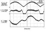
ここで、種々の条件下で本発明のインバータ制御装置を動作させた場合の結果を図14〜図16に示す。図14はキャリア周波数が3.3kHzの場合、図15は5kHzの場合、図16は7.5kHzの場合の動作結果であり、リアクタ電流波形を比較すれば、リアクタ電流(もしくは交流電源電流)はキャリア周波数による依存性が大きいことがわかる。 Here, the result at the time of operating the inverter control apparatus of this invention on various conditions is shown in FIGS. FIG. 14 shows the operation results when the carrier frequency is 3.3 kHz, FIG. 15 shows the case of 5 kHz, and FIG. 16 shows the operation result of 7.5 kHz. When the reactor current waveforms are compared, the reactor current (or AC power supply current) is It can be seen that the dependence on the carrier frequency is large.
また、それぞれの交流電源力率値をディジタルパワーメータにて測定したところ、図14のキャリア周波数が3.3kHzの時には0.878、図15の5kHzの時には0.956、図16の7.5kHzの時には0.962となった。 Further, when each AC power source power factor value was measured with a digital power meter, it was 0.878 when the carrier frequency in FIG. 14 was 3.3 kHz, 0.956 when 5 kHz in FIG. 15, and 7.5 kHz in FIG. At that time, it was 0.962.
なお、このときの諸元としては、小容量リアクタのインダクタンス値が0.5mH、小容量コンデンサの容量が10μF、交流電源が220V(50Hz)、インバータ運転周波数が57Hz(ここではモータの極数は2極のため、インバータ運転周波数とモータ速度指令値は等しい)、交流電源における入力電力が900Wである。 The specifications at this time are as follows: the inductance value of the small capacity reactor is 0.5 mH, the capacity of the small capacity capacitor is 10 μF, the AC power source is 220 V (50 Hz), the inverter operating frequency is 57 Hz (here, the number of poles of the motor is The inverter operating frequency and the motor speed command value are equal because of two poles), and the input power in the AC power supply is 900W.
ここで、例えば予め設定した交流電源力率値が0.9である場合には、キャリア周波数を3.3kHz〜5kHzの間に設定すれば良いことになり、最終的には予め設定した交流電源力率値(この場合は0.9)を満足しつつ、最もキャリア周波数が低くなるように決定する。 Here, for example, when the preset AC power factor value is 0.9, the carrier frequency may be set between 3.3 kHz and 5 kHz, and finally the preset AC power source is set. While satisfying the power factor value (0.9 in this case), the carrier frequency is determined to be the lowest.
以上により、予め設定された交流電源力率値を満足することが可能となり、必要最小限のキャリア周波数を設定することにより、インバータ損失を必要最小限に抑制することが可能となる。 As described above, the preset AC power source power factor value can be satisfied, and the inverter loss can be suppressed to the minimum necessary by setting the minimum necessary carrier frequency.
(実施の形態6)
図17に、上記のインバータ制御装置を利用した空気調和機の構成例を示す。同図に示すように、空気調和機は、上記のインバータ制御装置100を用いており、さらに、電動圧縮機82に加えて、室内ユニット92、室外ユニット95及び四方弁91からなる冷凍サイクルを備えている。室内ユニット92は室内送風機93と室内熱交換器94とから構成され、また室外ユニット95は室外熱交換器96、室外送風機97及び膨張弁98より構成される。
(Embodiment 6)
In FIG. 17, the structural example of the air conditioner using said inverter control apparatus is shown. As shown in the figure, the air conditioner uses the
電動圧縮機82はインダクションモータ4により駆動され、インダクションモータ4はインバータ制御装置100により駆動される。冷凍サイクル中は熱媒体である冷媒が循環する。冷媒は電動圧縮機82により圧縮され、室外熱交換器96にて室外送風機97からの送風により室外の空気と熱交換され、また室内熱交換器94にて室内送風機93からの送風により室内の空気と熱交換される。
The
なお、上記の実施形態ではインダクションモータについて説明を行なったが、本発明はその他のモータについても適用可能なものであることは言うまでもない。 Although the induction motor has been described in the above embodiment, it goes without saying that the present invention can also be applied to other motors.
本発明は、小型・軽量・低コストのモータ駆動用インバータ制御装置を提供し、空気調和機等に使用されるモータの制御装置として有用である。 INDUSTRIAL APPLICABILITY The present invention provides a motor drive inverter control device that is small, light, and low cost, and is useful as a motor control device used in an air conditioner or the like.
1 交流電源
2 整流回路
3 インバータ
4 インダクションモータ
11 小容量リアクタ
12 小容量コンデンサ
13 V/F制御パターン
14 モータ電圧指令作成部
15 PN電圧検出部
16 PN電圧補正部
17 モータ電圧指令補正部
18 PWM制御部
19 直流電圧基準値演算部
DESCRIPTION OF
Claims (7)
外部から与えられるモータの速度指令値に基づき、前記モータの各相電圧指令値を作成するモータ電圧指令作成手段と、
前記インバータの直流電圧値を検出し直流電圧検出値として出力するPN電圧検出手段と、
前記インバータの直流電圧基準値を決定する直流電圧基準値演算手段と、
前記直流電圧基準値を前記直流電圧検出値で除算することによりPN電圧補正係数を導出するPN電圧補正手段と、
前記モータ電圧指令作成手段から得られる各相電圧指令値と、前記PN電圧補正手段の出力値であるPN電圧補正係数とを乗算することにより各相電圧指令値の補正を行なうモータ電圧指令補正手段とを備え、
前記PN電圧補正手段は、前記直流電圧検出値が前記直流電圧基準値以上の場合において使用されるモードであって前記PN電圧補正係数に1を設定する第1のモードと、前記PN電圧補正係数に、前記直流電圧基準値を前記直流電圧検出値で除算して得られた値をそのまま設定する第2のモードとを有する
ことを特徴とするインバータ制御装置。 An inverter control device comprising: a rectifier circuit that converts AC power from an AC power source into DC power; and an inverter that converts DC power from the rectifier circuit into AC power having a desired frequency and desired voltage and supplies the AC power to a motor. The rectifier circuit includes a diode bridge and a predetermined small-capacity reactor connected to an AC input side or a DC output side of the diode bridge, and between the DC buses of the inverter, the regenerative energy of the motor In an inverter control device for driving a motor provided with a predetermined small-capacitance capacitor for absorbing
Motor voltage command creating means for creating each phase voltage command value of the motor based on the speed command value of the motor given from the outside;
PN voltage detection means for detecting a DC voltage value of the inverter and outputting it as a DC voltage detection value ;
DC voltage reference value calculating means for determining a DC voltage reference value of the inverter;
PN voltage correction means for deriving a PN voltage correction coefficient by dividing the DC voltage reference value by the DC voltage detection value ;
Motor voltage command correction means for correcting each phase voltage command value by multiplying each phase voltage command value obtained from the motor voltage command creation means by a PN voltage correction coefficient which is an output value of the PN voltage correction means. And
The PN voltage correction means is a mode used when the DC voltage detection value is equal to or greater than the DC voltage reference value and sets the PN voltage correction coefficient to 1, and the PN voltage correction coefficient And a second mode in which a value obtained by dividing the DC voltage reference value by the DC voltage detection value is set as it is.
前記圧縮機を駆動するためのモータと、
整流回路からの直流電力を可変電圧、可変周波数の交流電力に変換して前記モータに供給する請求項1または2記載のインバータ制御装置と
を備えたことを特徴とする空気調和機。 A compressor for compressing the refrigerant;
A motor for driving the compressor;
An air conditioner comprising: the inverter control device according to claim 1, wherein the inverter control device converts DC power from a rectifier circuit into AC power having variable voltage and variable frequency and supplies the AC power to the motor.
Priority Applications (3)
| Application Number | Priority Date | Filing Date | Title |
|---|---|---|---|
| JP2004054287A JP3955285B2 (en) | 2003-03-27 | 2004-02-27 | Inverter control device for motor drive and air conditioner |
| US10/809,485 US6972541B2 (en) | 2003-03-27 | 2004-03-26 | Inverter control device for driving a motor and an air conditioner |
| CNB2004100314753A CN1282301C (en) | 2003-03-27 | 2004-03-29 | Frequency changer controller for driving motor and air-conditioner |
Applications Claiming Priority (2)
| Application Number | Priority Date | Filing Date | Title |
|---|---|---|---|
| JP2003088439 | 2003-03-27 | ||
| JP2004054287A JP3955285B2 (en) | 2003-03-27 | 2004-02-27 | Inverter control device for motor drive and air conditioner |
Publications (3)
| Publication Number | Publication Date |
|---|---|
| JP2004312990A JP2004312990A (en) | 2004-11-04 |
| JP2004312990A5 JP2004312990A5 (en) | 2005-07-21 |
| JP3955285B2 true JP3955285B2 (en) | 2007-08-08 |
Family
ID=33455424
Family Applications (1)
| Application Number | Title | Priority Date | Filing Date |
|---|---|---|---|
| JP2004054287A Expired - Fee Related JP3955285B2 (en) | 2003-03-27 | 2004-02-27 | Inverter control device for motor drive and air conditioner |
Country Status (3)
| Country | Link |
|---|---|
| US (1) | US6972541B2 (en) |
| JP (1) | JP3955285B2 (en) |
| CN (1) | CN1282301C (en) |
Families Citing this family (28)
| Publication number | Priority date | Publication date | Assignee | Title |
|---|---|---|---|---|
| WO2004025820A1 (en) * | 2002-09-13 | 2004-03-25 | Tokyo Electron Limited | Rotation drive device and rotation drive method |
| US7207711B2 (en) * | 2002-12-23 | 2007-04-24 | Premark Feg L.L.C. | Mixing device with variable speed drive and related control features |
| US7273315B2 (en) * | 2002-12-23 | 2007-09-25 | Premark Feg Llc | Mixing device with variable speed drive and related control features |
| JP2004289985A (en) * | 2003-03-25 | 2004-10-14 | Matsushita Electric Ind Co Ltd | Inverter controller for driving motor and air conditioner |
| JP3980005B2 (en) * | 2003-03-28 | 2007-09-19 | 松下電器産業株式会社 | Inverter control device for motor drive and air conditioner |
| JP3955286B2 (en) * | 2003-04-03 | 2007-08-08 | 松下電器産業株式会社 | Inverter control device for motor drive and air conditioner |
| JP3955287B2 (en) * | 2003-04-03 | 2007-08-08 | 松下電器産業株式会社 | Inverter control device for motor drive and air conditioner |
| US7395527B2 (en) | 2003-09-30 | 2008-07-01 | International Business Machines Corporation | Method and apparatus for counting instruction execution and data accesses |
| US7415705B2 (en) | 2004-01-14 | 2008-08-19 | International Business Machines Corporation | Autonomic method and apparatus for hardware assist for patching code |
| US7895382B2 (en) | 2004-01-14 | 2011-02-22 | International Business Machines Corporation | Method and apparatus for qualifying collection of performance monitoring events by types of interrupt when interrupt occurs |
| JP4304122B2 (en) * | 2004-05-25 | 2009-07-29 | 三菱電機株式会社 | Electric vehicle control device |
| US7877815B2 (en) * | 2006-01-20 | 2011-01-25 | Kyocera Corporation | Battery authentication in a wireless communication device |
| CN101873078B (en) * | 2009-04-21 | 2012-11-21 | 比亚迪股份有限公司 | Controllable rectifying device and electromotor using the same |
| WO2013136753A1 (en) * | 2012-03-15 | 2013-09-19 | パナソニック株式会社 | Power feed device of inductive charging device |
| WO2013136755A1 (en) * | 2012-03-16 | 2013-09-19 | パナソニック株式会社 | Power feed device of inductive charging device |
| JP5664588B2 (en) * | 2012-04-20 | 2015-02-04 | 株式会社安川電機 | Power regeneration device and power conversion device |
| JP5421433B2 (en) * | 2012-06-25 | 2014-02-19 | ファナック株式会社 | Motor control device that reduces power consumption of control power supply during power outage |
| JP6176121B2 (en) * | 2014-01-10 | 2017-08-09 | 住友電気工業株式会社 | Power converter and three-phase AC power supply |
| JP5742980B1 (en) * | 2014-02-19 | 2015-07-01 | ダイキン工業株式会社 | Power converter control method |
| EP3116120A4 (en) * | 2014-03-05 | 2017-10-18 | Nidec Servo Corporation | Motor system |
| JP6614825B2 (en) * | 2015-06-30 | 2019-12-04 | 日立ジョンソンコントロールズ空調株式会社 | Power conversion device, motor drive device, refrigeration device |
| JP6701637B2 (en) * | 2015-07-21 | 2020-05-27 | ダイキン工業株式会社 | Inverter device |
| US11052360B2 (en) | 2017-02-28 | 2021-07-06 | Illinois Tool Works Inc. | Mixing machine system |
| WO2018160518A1 (en) | 2017-02-28 | 2018-09-07 | Illinois Tool Works Inc. | Mixing machine system |
| GB2573247B (en) | 2017-02-28 | 2022-04-20 | Illinois Tool Works | Mixing machine with VFD based diagnostics |
| GB2583237B (en) | 2017-12-21 | 2022-06-15 | Illinois Tool Works | Mixing machine |
| CN108809073B (en) * | 2018-05-31 | 2020-01-17 | 奥克斯空调股份有限公司 | APFC circuit voltage control method and system and air conditioner |
| WO2022172505A1 (en) * | 2021-02-10 | 2022-08-18 | パナソニックIpマネジメント株式会社 | Electric motor driving device |
Family Cites Families (19)
| Publication number | Priority date | Publication date | Assignee | Title |
|---|---|---|---|---|
| US4992718A (en) * | 1989-09-11 | 1991-02-12 | Nihon Patent Electric Co., Ltd. | Electric floor cleaner with a soft start function |
| JPH03155392A (en) * | 1989-11-10 | 1991-07-03 | Toshiba Corp | Current detecting unit |
| US6002218A (en) * | 1992-11-20 | 1999-12-14 | Fujitsu General Limited | Control device for air conditioner |
| US5457375A (en) * | 1994-05-27 | 1995-10-10 | Emerson Electric Co. | Sensorless commutation controller for a poly-phase dynamoelectric machine |
| US5561595A (en) * | 1995-03-24 | 1996-10-01 | Magl Power Inc. | Power inverter with input line conditioning |
| JP3519540B2 (en) | 1996-03-28 | 2004-04-19 | 東芝キヤリア株式会社 | DC power supply and air conditioner |
| DE69914242T2 (en) * | 1998-03-23 | 2004-11-04 | Hitachi, Ltd. | Control device for a brushless motor and machine with a brushless motor |
| JP4154679B2 (en) * | 1998-04-18 | 2008-09-24 | 株式会社安川電機 | Electric motor power failure processing method and control device therefor |
| US6229278B1 (en) * | 1999-09-29 | 2001-05-08 | Rockwell Technologies, Llc | Voltage and current limiting method and apparatus for a voltage/frequency drive |
| US6489692B1 (en) * | 1999-12-13 | 2002-12-03 | Capstone Turbine Corporation | Method and apparatus for controlling rotation of magnetic rotor |
| US6414455B1 (en) * | 2000-04-03 | 2002-07-02 | Alvin J. Watson | System and method for variable drive pump control |
| JP4465129B2 (en) * | 2000-07-14 | 2010-05-19 | パナソニック株式会社 | Brushless motor driving apparatus and driving method |
| EP1492223A4 (en) * | 2002-03-22 | 2005-12-14 | Matsushita Electric Ind Co Ltd | Synchronous reluctance motor control device |
| EP1429450B1 (en) * | 2002-12-12 | 2008-02-13 | Matsushita Electric Industrial Co., Ltd. | Motor control apparatus |
| JP2004289985A (en) * | 2003-03-25 | 2004-10-14 | Matsushita Electric Ind Co Ltd | Inverter controller for driving motor and air conditioner |
| JP3980005B2 (en) * | 2003-03-28 | 2007-09-19 | 松下電器産業株式会社 | Inverter control device for motor drive and air conditioner |
| JP3955287B2 (en) * | 2003-04-03 | 2007-08-08 | 松下電器産業株式会社 | Inverter control device for motor drive and air conditioner |
| JP2004350493A (en) * | 2003-04-28 | 2004-12-09 | Matsushita Electric Ind Co Ltd | Inverter controller for driving motor and air conditioner using the same |
| US7078876B2 (en) * | 2003-07-07 | 2006-07-18 | Pentadyne Power Corporation | Feedforward controller for synchronous reluctance machines |
-
2004
- 2004-02-27 JP JP2004054287A patent/JP3955285B2/en not_active Expired - Fee Related
- 2004-03-26 US US10/809,485 patent/US6972541B2/en not_active Expired - Lifetime
- 2004-03-29 CN CNB2004100314753A patent/CN1282301C/en not_active Expired - Fee Related
Also Published As
| Publication number | Publication date |
|---|---|
| US6972541B2 (en) | 2005-12-06 |
| US20040232876A1 (en) | 2004-11-25 |
| CN1282301C (en) | 2006-10-25 |
| JP2004312990A (en) | 2004-11-04 |
| CN1534859A (en) | 2004-10-06 |
Similar Documents
| Publication | Publication Date | Title |
|---|---|---|
| JP3955285B2 (en) | Inverter control device for motor drive and air conditioner | |
| JP3955286B2 (en) | Inverter control device for motor drive and air conditioner | |
| JP3980005B2 (en) | Inverter control device for motor drive and air conditioner | |
| US6924618B2 (en) | Inverter controller for driving motor, and air conditioner | |
| US10236805B2 (en) | Methods and systems for controlling an electric motor | |
| JP3519540B2 (en) | DC power supply and air conditioner | |
| JP4561219B2 (en) | Inverter control device for motor drive and air conditioner using the same | |
| JP2010124585A (en) | Motor-driving inverter control device and air-conditioner having the same | |
| JP4911109B2 (en) | Power converter and air conditioner equipped with the same | |
| JP4186750B2 (en) | Motor control device | |
| JP2012165582A (en) | Motor controller | |
| JPH0715966A (en) | Electric motor drive device | |
| JP2010051142A (en) | Inverter controller for motor drive and air conditioner | |
| JP4984495B2 (en) | Inverter controller for motor drive | |
| WO2022172417A1 (en) | Power conversion device, motor drive device, and refrigeration cycle application machine | |
| JP5040160B2 (en) | Inverter controller for motor drive | |
| WO2021157176A1 (en) | Electric motor drive device | |
| JP2010051143A (en) | Inverter controller for motor drive and air conditioner | |
| JP4915078B2 (en) | Inverter controller for motor drive | |
| JP2005124298A (en) | Inverter control unit for driving induction motor and air conditioner | |
| JP4439869B2 (en) | Inverter control device and air conditioner | |
| KR101996260B1 (en) | Power converting apparatus and air controller having the same | |
| KR100925276B1 (en) | Motor controller and method for controlling the same | |
| JP2009131001A (en) | Inverter controller for driving motor | |
| JP2000227243A (en) | Air-conditioning device utilizing power converting device |
Legal Events
| Date | Code | Title | Description |
|---|---|---|---|
| A521 | Written amendment |
Free format text: JAPANESE INTERMEDIATE CODE: A523 Effective date: 20050201 |
|
| A621 | Written request for application examination |
Free format text: JAPANESE INTERMEDIATE CODE: A621 Effective date: 20050201 |
|
| A131 | Notification of reasons for refusal |
Free format text: JAPANESE INTERMEDIATE CODE: A131 Effective date: 20061107 |
|
| A521 | Written amendment |
Free format text: JAPANESE INTERMEDIATE CODE: A523 Effective date: 20061208 |
|
| RD03 | Notification of appointment of power of attorney |
Free format text: JAPANESE INTERMEDIATE CODE: A7423 Effective date: 20061208 |
|
| TRDD | Decision of grant or rejection written | ||
| A01 | Written decision to grant a patent or to grant a registration (utility model) |
Free format text: JAPANESE INTERMEDIATE CODE: A01 Effective date: 20070403 |
|
| A61 | First payment of annual fees (during grant procedure) |
Free format text: JAPANESE INTERMEDIATE CODE: A61 Effective date: 20070501 |
|
| R150 | Certificate of patent or registration of utility model |
Free format text: JAPANESE INTERMEDIATE CODE: R150 |
|
| FPAY | Renewal fee payment (event date is renewal date of database) |
Free format text: PAYMENT UNTIL: 20110511 Year of fee payment: 4 |
|
| FPAY | Renewal fee payment (event date is renewal date of database) |
Free format text: PAYMENT UNTIL: 20120511 Year of fee payment: 5 |
|
| FPAY | Renewal fee payment (event date is renewal date of database) |
Free format text: PAYMENT UNTIL: 20130511 Year of fee payment: 6 |
|
| FPAY | Renewal fee payment (event date is renewal date of database) |
Free format text: PAYMENT UNTIL: 20130511 Year of fee payment: 6 |
|
| FPAY | Renewal fee payment (event date is renewal date of database) |
Free format text: PAYMENT UNTIL: 20140511 Year of fee payment: 7 |
|
| LAPS | Cancellation because of no payment of annual fees |