CN1282301C - Frequency changer controller for driving motor and air-conditioner - Google Patents
Frequency changer controller for driving motor and air-conditioner Download PDFInfo
- Publication number
- CN1282301C CN1282301C CNB2004100314753A CN200410031475A CN1282301C CN 1282301 C CN1282301 C CN 1282301C CN B2004100314753 A CNB2004100314753 A CN B2004100314753A CN 200410031475 A CN200410031475 A CN 200410031475A CN 1282301 C CN1282301 C CN 1282301C
- Authority
- CN
- China
- Prior art keywords
- voltage
- frequency
- motor
- value
- frequency converter
- Prior art date
- Legal status (The legal status is an assumption and is not a legal conclusion. Google has not performed a legal analysis and makes no representation as to the accuracy of the status listed.)
- Expired - Fee Related
Links
Images


Classifications
-
- H—ELECTRICITY
- H02—GENERATION; CONVERSION OR DISTRIBUTION OF ELECTRIC POWER
- H02P—CONTROL OR REGULATION OF ELECTRIC MOTORS, ELECTRIC GENERATORS OR DYNAMO-ELECTRIC CONVERTERS; CONTROLLING TRANSFORMERS, REACTORS OR CHOKE COILS
- H02P27/00—Arrangements or methods for the control of AC motors characterised by the kind of supply voltage
- H02P27/04—Arrangements or methods for the control of AC motors characterised by the kind of supply voltage using variable-frequency supply voltage, e.g. inverter or converter supply voltage
- H02P27/045—Arrangements or methods for the control of AC motors characterised by the kind of supply voltage using variable-frequency supply voltage, e.g. inverter or converter supply voltage whereby the speed is regulated by measuring the motor speed and comparing it with a given physical value
Landscapes
- Engineering & Computer Science (AREA)
- Power Engineering (AREA)
- Control Of Ac Motors In General (AREA)
Abstract
An inverter control device for driving a motor with small size, light weight and low cost is provided. The inverter control device generates PN voltage correction coefficient by dividing the reference DC voltage by the detected DC voltage, and corrects the voltage command of each phase by multiplying the voltage command of each phase obtained by the motor voltage command generator with the PN voltage correction coefficient output from the PN voltage corrector, thus resulting in the corrected motor voltage command. The inverter control device has, in generating PN voltage correction coefficient, a first mode in which the PN voltage correction coefficient is set to 1 when the DC voltage value is more than the reference DC voltage, and a second mode in which the value obtained by dividing the reference DC voltage by the detected DC voltage is set to the PN voltage correction coefficient.
Description
Technical field
The present invention relates to frequency changer controller for driving motor and air regulator.
Background technology
The general induction motor that uses as universal frequency converter etc. drives use frequency-converter device, and the induction motor driving of V/F control mode as shown in figure 18 is known (such as the 661st~711 page of reference non-patent literature 1) with frequency changer controller.
In Figure 18, main circuit, by: continuous-current plant 113, frequency converter 3 and induction motor 14 constitute, and continuous-current plant 113 constitutes by AC power 1, rectification circuit 2, for the smoothing capacity 112 of the direct voltage source savings electric energy of frequency converter 3, the reactance coil of using for the power factor of improving AC power 1 111.
On the other hand, control circuit, by: the speed command ω of the induction motor 4 that applies according to the outside
*Decision is applied to the V/F control model portion 13 of the motor voltage value on the induction motor 4, according to the motor voltage value of V/F control model portion 13 decision, the motor voltage instruction that makes each phase voltage command value of induction motor 4 makes portion 14, makes each phase voltage command value that portion 14 makes according to being instructed by motor voltage, and the PWM control part 18 that generates the pwm signal of frequency converter 3 constitutes.
In addition, shown in Figure 19 is an example of general V/F control model portion 13.
As shown in figure 19, with respect to speed command ω
*, the motor voltage value that is applied on the induction motor 4 is unique definite.Ordinary circumstance is with speed command ω
*Store into as chart values with the value of motor voltage value in the memory of arithmetic unit such as microprocessor, for the speed command ω beyond the chart values
*Carry out linear interpolation from chart values, and derive the motor voltage value.
Here, shown in Figure 20 is when AC power 1 for 220V (ac power frequency 50Hz), frequency converter 3 be input as 1.5kW, when smoothing capacity 112 is 1500 μ F, be used to improve under the situation of reactance coil 111 for 50mH and 20mH of power factor the higher harmonic component of AC power electric current and relation with respect to the number of times of ac power frequency.Figure 20 shows in the lump with IEC (the International Electrotechnical Commi) specification, when being used to improve the reactance coil 111 of power factor under the situation of 5mH, particularly the 3rd higher harmonic component substantially exceeds the IEC standard, but when it is under the situation of 20mH, in the higher harmonic component till 40 times, can also meet the IEC standard.
Therefore, particularly when high capacity,, must take further to increase the measures such as inductance value of the reactance coil 111 that is used to improve power factor in order to meet the IEC standard, increase so will produce the maximization, weight of frequency-converter device, even cause problem such as cost raising.
Therefore, increase as the inductance value of the reactance coil 111 that suppresses to be used to improve power factor, reduce the continuous-current plant of power supply higher harmonic component and realization High Power Factor, proposed the scheme (such as reference patent documentation 1) of continuous-current plant as shown in figure 21.
In Figure 21, the AC supply voltage of AC power 1 is applied to by diode D1~D4 does that bridge-type connects and on the AC input terminal of the full-wave rectifying circuit that forms, by reactance coil Lin its output is charged to intermediate capacitance C, the electric charge of this intermediate capacitance C is discharged to smoothing capacity CD, and direct voltage is offered load resistance RL.At this moment, connection transistor Q1 on load one side of reactance coil Lin and the positive and negative direct current path that is connected with intermediate capacitance C drives this transistor Q1 by base drive circuit.
And, continuous-current plant also possesses pulse generating circuit I1, I2 and the pseudo-resistance R dm that applies pulse voltage to base drive circuit G1, pulse generating circuit I1, I2, respectively by the circuit of the zero crossing that detects AC supply voltage, begin to the instantaneous value of AC supply voltage with till the both end voltage of intermediate capacitance C equates, in the pulse current circuit formation of pseudo-resistance R dm upper reaches extra pulse electric current from the detection of zero crossing.
Here, pulse generating circuit I1 is preceding half half period of AC supply voltage, pulsing voltage, and pulse generating circuit I2 is at the later half pulsing voltage of the half period of AC supply voltage.
In addition, when transistor Q1 is set to conducting state, forcibly when the overcurrent of reactance coil Lin upper reaches, for the electric charge that does not make intermediate capacitance C discharges by transistor Q1, connect a diode D5 who is used to prevent reverse current, and, at the reactance coil Ldc that the electric charge of intermediate capacitance C is connected in series on the path of smoothing capacity CD discharge and is used to prevent the diode D6 of reverse current and improves smooth effect.
In above-mentioned formation, be no more than between the phase region of both end voltage of intermediate capacitance C part or all at the instantaneous value of AC supply voltage, Q1 is set to conducting state with transistor, in the time of maximization that thus can restraining device, reaches and reduces higher harmonic component and High Power Factorization.
[patent documentation 1] spy opens flat 9-266674 communique
[non-patent literature 1] with reference to ' frequency conversion drive handbook ' (frequency conversion drive handbook editorial board edit, nineteen ninety-five front page, Nikkan Kogyo Shimbun issues)
But, above-mentioned formation in the past, still exist capacious level and smooth with electric capacity CD and reactance coil Lin (analog result when patent documentation 1 has been put down in writing 1500 μ F, 6.2mH), and, owing to still possess intermediate capacitance C, transistor Q1, base drive circuit G1, pulse generating circuit I1, I2, pseudo-resistance R dm, prevent diode D5, the D6 of reverse current, the reactance coil Ldc of raising smooth effect, therefore, still there is the increase of the maximization of companion devices and number of components and the problem that causes cost to increase.
Summary of the invention
The present invention is in order to solve such problem in the past, and its purpose is to provide volume little, in light weight, frequency changer controller for driving motor cheaply.
Frequency changer controller of the present invention comprises: the alternating current of AC power is transformed into galvanic rectification circuit and the direct current of this rectification circuit is transformed into the alternating current of frequency with hope, voltage and offers the frequency converter of motor.Rectification circuit, by: the low capacity reactance of the regulation of diode bridge, the interchange input side that is connected in this diode bridge or direct current outlet side constitutes.Between the dc bus of frequency converter, be provided for absorbing the low capacity electric capacity of regulation of the regenerated energy of motor.Frequency changer controller possesses: according to the motor voltage value that is applied to described motor that speed value determined of the motor that gives based on the outside, make the motor voltage instruction implementing device of each phase voltage command value of described motor; Detect the PN voltage check device of the dc voltage value of frequency converter; Determine the dc voltage reference value arithmetic unit of the dc voltage reference value of frequency converter; PN voltage compensating device; Motor voltage instruction compensating device.PN voltage compensating device, by using dc voltage reference value divided by dc voltage detection value, thereby derive PN voltage augmenting factor, have as the mode when dc voltage value is higher than dc voltage reference value, used, PN voltage augmenting factor is set at 1 first mode and the result that dc voltage reference value obtains divided by dc voltage detection value directly is set at second mode of PN voltage augmenting factor.Motor voltage instruction compensating device is by instructing motor voltage each phase voltage command value that implementing device obtains and PN voltage augmenting factor as the output valve of PN voltage compensating device to carry out multiplying and each phase voltage command value is carried out revisal.
Constitute by above-mentioned, by adopting low capacity electric capacity and low capacity reactance, can realize the frequency changer controller for driving motor that volume is little, in light weight, cost is low, even significantly change under the situation that makes the motor driven difficulty or can't drive at the frequency converter direct voltage, also can make the voltage that is applied on the motor make the frequency converter action substantially fixedly, keep the driving of motor, the change of AC power electric current can also be suppressed, and the power factor of AC power and the higher harmonic component of inhibition AC power electric current can be improved.
And, the dc voltage reference value of determining by the dc voltage reference value arithmetic unit, the motor speed command value that can corresponding outside gives and changing.Constitute by this, can suppress the radio-frequency component of AC power electric current more.
And, also can control of conversion device running frequency, thus the resonance frequency of avoiding the frequency converter running frequency to be fixed on the frequency of even-multiple with ac power frequency is the center, has before and after it in frequency range of band width of regulation.Constitute by this, can prevent the instability action of motor, realize stable driving by avoiding the covibration of frequency converter frequency and ac power frequency.
And, determine the combination of low capacity reactance and low capacity electric capacity, thereby make based on the resonance frequency of low capacity reactance and low capacity electric capacity 40 times greater than ac power frequency.Constitute by this, can suppress the higher harmonic component of AC power electric current, reach the IEC standard.
And, also can determine to make the capacity of low capacity electric capacity when frequency converter stops, the maximum of the dc voltage value of rising is withstand voltage littler than element.By determining the capacity of low capacity electric capacity, make the maximum of frequency converter dc voltage value drive the withstand voltage littler of electric component, the destruction that can prevent peripheral circuit than each.
Thereby the carrier frequency that also can determine frequency converter satisfies the power factor value of predefined alternating current.Constitute by this, can satisfy predefined power factor value,, the loss of frequency converter can be suppressed to minimum by the setting little carrier frequency of trying one's best.
According to the present invention, because each phase voltage command value of revisal suitably, so can use low capacity electric capacity and low capacity reactance.Thus, can realize the frequency changer controller for driving motor that volume is little, in light weight, cost is low, even significantly change under the situation that makes the motor driven difficulty or can't drive at the frequency converter direct voltage, when also can make the voltage that is applied on the motor make the frequency converter action basicly stablely, can select to be devoted to keep motor more stable driving the operation field and suppress the change of AC power electric current, and the higher harmonic component that improves the power factor of AC power and suppress the AC power electric current operation field of three compositions particularly.
Description of drawings
Fig. 1 is that the induction motor of the expression embodiment of the invention 1 drives the system's pie graph with frequency changer controller.
Fig. 2 is the figure of first mode of the PN voltage compensating device of the expression embodiment of the invention 1.
Fig. 3 is the figure of second mode of the PN voltage compensating device of the expression embodiment of the invention 1.
Fig. 4 is the figure of the result of the action of the expression embodiment of the invention 1.
The figure of sense of current when Fig. 5 is the action of the expression embodiment of the invention 1.
Fig. 6 (a) is the figure of action of first mode of the PN voltage compensating device of the expression embodiment of the invention 1, (b) is the figure of action of second mode of the expression embodiment of the invention 1.
Fig. 7 is the figure of the result of the action of first mode of the PN voltage compensating device of the expression embodiment of the invention 1.
Fig. 8 is the figure of the result of the action of second mode of the PN voltage compensating device of the expression embodiment of the invention 1.
Fig. 9 is the figure of characteristic of the dc voltage reference value of the expression embodiment of the invention 2.
Figure 10 is the figure of the action of the expression embodiment of the invention 2.
Figure 11 is the figure of the result of the action of the expression embodiment of the invention 1.
Figure 12 is that the induction motor of the expression embodiment of the invention 3 drives the figure with first the result of the action of frequency changer controller.
Figure 13 is that the induction motor of the expression embodiment of the invention 3 drives the figure with second the result of the action of frequency changer controller.
Figure 14 is that the induction motor of the expression embodiment of the invention 5 drives the figure with first the result of the action of frequency changer controller.
Figure 15 is that the induction motor of the expression embodiment of the invention 5 drives the figure with second the result of the action of frequency changer controller.
Figure 16 is that the induction motor of the expression embodiment of the invention 5 drives the figure with the 3rd the result of the action of frequency changer controller.
Figure 17 is the formation block diagram of an embodiment of expression air regulator of the present invention.
Figure 18 is that general induction motor drives the system's pie graph with frequency changer controller.
Figure 19 is the figure of an example of the general V/F control model of expression.
Figure 20 is that the induction motor of expression Figure 18 drives with the higher harmonic component of the AC power electric current of frequency-converter device and line chart with respect to the relation of the number of times of ac power frequency.
Figure 21 is continuous-current plant figure in the past.
Among the figure: 1-AC power, 2-rectification circuit, 3-frequency converter, the 4-induction motor, the reactance of 11-low capacity, 12-low capacity electric capacity, 13-V/F control model, the instruction of 14-motor voltage makes portion, the 15-PN voltage detection department, 16-PN voltage correcting section, 17-motor voltage instruction correcting section, the 18-PWM control part, 19-dc voltage reference value operational part.
Embodiment
Following with reference to accompanying drawing, embodiments of the invention are described.
Fig. 1 represents that the induction motor of the embodiment of the invention 1 drives the system's pie graph with frequency changer controller.In Fig. 1, the main circuit of frequency changer controller by: AC power 1, with alternating current be transformed into low capacity electric capacity 12 below galvanic diode bridge 2, low capacity reactance 11, the 100 μ F below the 2mH, with direct current be transformed into the frequency converter 3 of alternating current, by constituting by the electrically driven (operated) induction motor 4 of the interchange of frequency converter 3 conversion.
On the other hand, the control circuit of frequency changer controller comprises: V/F control model portion 13, motor voltage instruction make portion 14, PN voltage detection department 15, PN voltage correcting section 16, motor voltage instruction correcting section 17, PWM control part 18, dc voltage reference value operational part 19.
V/F control model portion 13 is according to the speed command ω of the induction motor 4 that is given by the outside
*And decision puts on the motor voltage value on the induction motor 4.The motor voltage instruction makes portion 14, according to the motor voltage value by 13 decisions of V/F control model portion, makes each phase voltage command value of induction motor 4.PN voltage detection department 15, the dc voltage value of detection frequency converter 3.Dc voltage reference value operational part 19, the dc voltage reference value of decision frequency converter 3.PN voltage correcting section 16 dc voltage reference value of the frequency converter 3 of the dc voltage reference value operational part 19 decision dc voltage detection value with the frequency converter 3 that is obtained by PN voltage detection department 15 is compared, and comparative result is derived PN voltage augmenting factor thus.Motor voltage instruction correcting section 17, multiply each other with PN voltage augmenting factor by making each phase voltage command value that portion 14 obtains as the output valve of PN voltage correcting section 16 by motor instruction, carry out the voltage revisal of each phase voltage command value, and make the motor voltage instruction compensating value of induction motor 4.PWM control part 18 is according to the pwm signal of the motor voltage instruction compensating value generation frequency converter 3 that is made by motor voltage instruction correcting section 17.
In addition,, in above-mentioned prior art, illustrate, omitted at this for V/F control model portion 13.(induction motor of the V/F control mode of Figure 18 drives and uses frequency changer controller)
Below, the concrete action of the frequency changer controller of present embodiment is described.
Make portion 14 in the motor voltage instruction, the computing by formula (1) expression makes each phase voltage command value Vu
*, Vv
*, Vw
*
[formula 1]
Here, V
mBe motor voltage value by 13 decisions of V/F control model portion, θ
1Shown in formula (2), by to speed command ω
*Carry out time integral and derive.
[formula 2]
θ
1=∫ω
*dt ………(2)
PN voltage correcting section 16 has two manner of execution.Fig. 2 is the figure of first mode of expression PN voltage correcting section 16.PN voltage correcting section 16, the dc voltage detection value Vpn of the frequency converter 3 that utilization obtains by the dc voltage reference value Vpn0 of the frequency converter 3 of dc voltage reference value operational part 19 decision with by PN voltage detection department 15, shown in formula (3), derive PN voltage augmenting factor kpn.
[formula 3]
Here, Kpn_max is the maximum of predefined PN voltage augmenting factor.
And Fig. 3 shown in formula (4), derives PN voltage augmenting factor Kpn for the figure of second mode of expression PN voltage correcting section 16.
[formula 4]
And, in motor voltage instruction correcting section 17, adopt each phase voltage command value Vu
*, Vv
*, Vw
*With PN voltage augmenting factor Kpn, shown in formula (5), derive motor voltage instruction compensating value Vuh
*, Vvh
*, Vwh
*
[formula 5]
As mentioned above, the frequency changer controller of present embodiment is owing to adopt PN voltage augmenting factor to carry out the revisal of each phase voltage command value, therefore, even there is the change of PN voltage, the voltage that is applied on the motor also keeps basicly stable, do not need large bulk capacitance, and can use low capacity electric capacity.In addition, by using low capacity electric capacity, input current offers motor constantly, has improved the power factor of input current, thereby can realize the miniaturization of reactance coil.So, by adopting low capacity reactance coil and low capacity electric capacity, can realize the induction motor driving frequency-converter device that volume is little, in light weight, cost is low, even significantly change at the frequency converter direct voltage, under the driving difficulty of induction motor or the situation that can not drive, make the frequency converter action with also can making the voltage kept stable that is applied on the induction motor, keep driving induction motor.
Here, first motor and second motor to PN voltage correcting section 16 further describes.
Generally know that, the output torque of induction motor be applied to motor on square being directly proportional of voltage (such as, with reference to 33 pages of non-patent literature 1) for fear of the critical load off-capacity of induction motor, must guarantee the voltage that applies of motor.
So, in order to keep stabilized driving, in the interval of the big sub-dc voltage reference value Vpn0 of dc voltage detection value Vpn, by first mode that PN voltage augmenting factor Kpn is fixed as 1 PN voltage correcting section 16 to induction motor, prevent that motor from applying the minimizing of voltage, guarantees to export torque.
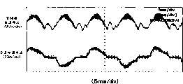
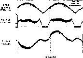
Fig. 4 drives with in the frequency changer controller speed command ω at induction motor of the present invention
*Near in the time of 100Hz the result of the action.If A during among concern Fig. 4 is during this, because the direct voltage V of frequency converter 3
PnDescend, make the motor current I of W phase
wShould shown in dotted linely must be positive direction, but opposite course negative direction.At this moment, become the electric current of generation direction of regeneration as shown in Figure 5, and do not have the AC power electric current I
AcState, if this state continuance, then three higher harmonic components increase.
In order to prevent the increase of these three higher harmonic components, as speed command ω
*In the time of near 100Hz,, obtain PN voltage augmenting factor K by second mode of PN voltage correcting section 16
Pn, shown in formula (5), derive motor voltage instruction compensating value V
Uh *, V
Vh *, V
Wh *
Fig. 6 (a) and (b) are pattern ground expression speed command W respectively
*In the time of near 100Hz, first mode of PN voltage correcting section 16 and the action of second mode.
Shown in Fig. 6 (b), in second mode, exist PN voltage augmenting factor in the situation below 1, this moment is owing to suppress motor voltage instruction compensating value V
Uh *, V
Vh *, V
Wh *So, compare the I of AC power electric current with first mode
AcPeak value be suppressed.
Fig. 7 is that expression is as speed command ω
*Near 100Hz, the result's who moves by first mode of PN voltage correcting section 16 figure, Fig. 8 result's that to be expression moved by second mode figure.
In fact, when PN voltage correcting section 16 is moved in second mode, the AC power electric current I
AcPeak value be suppressed, can lower three higher harmonic components of AC power electric current.
As mentioned above, by first mode and second mode of using PN voltage correcting section 16 simultaneously, the induction motor that can be implemented in the operation field of the stabilized driving of being devoted to keep induction motor or be devoted to suppress the operation field of three higher harmonic components of AC power electric current to select drives uses frequency changer controller.
In addition, the present invention is not limited to the induction motor driving by V/F control of the above embodiments and uses frequency changer controller, and the induction motor that also goes for well-known vector control drives uses frequency changer controller.
In addition, as drive motor of compressor of air regulator etc., can not use the situation of pulse generator uniform velocity transducer or as servo-drive etc., possess under the situation of velocity transducer, all can use the present invention.
In the present embodiment, according to the speed command ω of the induction motor 4 that gives by the outside
*And the dc voltage reference value V that change is derived by dc voltage reference value operational part 19
Pn0
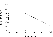
Fig. 9 is the speed command ω of expression according to the induction motor 4 that is given by the outside
*And the dc voltage reference value V that change is derived by dc voltage reference value operational part 19
Pn0The figure of an example.
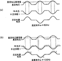
Figure 10 (a) and (b) are in the characteristic of dc voltage reference value operational part 19 shown in Figure 9, and the expression of pattern ground is as speed command ω respectively
*Figure for the action under the situation of 80Hz and 100Hz.
The situation of 100Hz shown in Figure 10 (b) is compared PN voltage augmenting factor K with the situation of the 80Hz shown in Figure 10 (a)
PnWhole decline, motor voltage instruction compensating value V
Uh *, V
Vh *, V
Wh *Also be suppressed.
Its result, induction motor 4 becomes the state that requires motor to apply voltage more, as shown in figure 11, the AC power electric current I
AcShorten during the immobilising state, can lower three higher harmonic components of AC power electric current.
The concrete grammar of the setting of frequency converter running frequency of the present invention below is described.
Because on induction motor of the present invention drives with frequency changer controller, employing be low capacity electric capacity, so as shown in figure 12, the direct voltage of frequency converter can carry out big pulsation with the frequency of the twice of ac power frequency fs.
Therefore, at frequency converter running frequency f
1Under the frequency for the even-multiple of ac power frequency fs, the phenomenon of frequency (frequency of the twice of the ac power frequency fs) synchro-resonance of frequency converter direct voltage and pulsation then takes place.
Figure 13 is the running frequency f of expression when frequency converter
1The figure of the result of the action when becoming the twice of ac power frequency fs.The Frequency Synchronization of frequency converter direct voltage and pulsation and produce covibration as can be seen, and negative flip-flop is overlapping in motor current.Therefore, brake torque can take place on induction motor, produce the baneful influence that makes the output torque reduce or increase motor losses.In addition, each element of Figure 13, the inductance value of low capacity reactance is 0.5mH, the electric capacity of low capacity electric capacity is 10 μ F, AC power is 220V (50Hz), and the frequency converter running frequency is that (here, the number of poles of motor is two utmost points to 100Hz, therefore the frequency converter running frequency equates with the motor speed command value), the frequency converter carrier frequency is 5kHz.
Therefore, in the present embodiment, setting frequency converter running frequency f
1The time, for fear of frequency converter running frequency f
1The frequency (frequency range) that is provided by formula (6) immobilizes, and sets frequency converter running frequency f
1
[formula 6]
f
1=2nf
s±Δf………(6)
Here, n is an integer, and Δ f is predefined band width, is basically to make above-mentioned covibration reduce ground setpoint frequency width Delta f.
And, as frequency converter running frequency f
1When surpassing the resonance frequency of obtaining by formula (6), change frequency converter running frequency f by the transition state of quickening or slow down quickly
1Thereby, avoid frequency converter running frequency f
1Be fixed on the resonance frequency.
In addition, might not want setpoint frequency width Delta f, also can be not set (can allow this moment Δ f=0) according to operation conditions (during underload etc.).
As mentioned above,, can prevent the instability action of induction motor, realize stable driving by avoiding the covibration of frequency converter frequency and ac power frequency.
The following concrete grammar of the specification of the low capacity electric capacity 12 that in frequency changer controller of the present invention, adopts of the relevant decision of explanation and low capacity reactance 11.
In frequency-converter device of the present invention, in order to suppress the higher harmonic component of AC power electric current, reach the IEC standard, the combination of decision low capacity electric capacity 12 and low capacity reactance 11 makes by low capacity electric capacity and the definite resonance frequency f of low capacity reactance
LC(LC resonance frequency) is bigger 40 times than ac power frequency fs.
Here, if the capacity of low capacity electric capacity 12 is decided to be C[F], the inductance value of low capacity reactance 11 is decided to be L[H], LC resonance frequency f then
LCCalculating shown in formula (7).
[formula 10]
That is, the combination of determining low capacity electric capacity 12 and low capacity reactance 11 makes it to satisfy f
LC>40fs.This is because in the IEC standard, in the higher harmonic component of AC power electric current, has stipulated till the 40th higher harmonics.
By utilizing above method, determine the combination of low capacity electric capacity 12 and low capacity reactance 11, can suppress the higher harmonic component of AC power electric current, reach the IEC standard.
Below, the determining of capacity of low capacity electric capacity 12 is described.
When frequency converter 3 stopped, low capacity electric capacity 12 absorbed the regenerated energy (putting aside the magnetic energy in the inductance composition of induction motor till before stop) of induction motors 4, and promoted the dc voltage value of frequency converter 3.Therefore, make the maximum of direct voltage of this moment, littlelyr than the withstand voltage capacity of determining low capacity electric capacity 12 of the composed component of the peripheral circuit of frequency converter 3.Thus, can prevent the destruction of peripheral circuit.
In addition, after the value of low capacity electric capacity 12 is determined, can determine the inductance value of low capacity reactance 11 automatically with above-mentioned method.
Embodiment 5
Below, the concrete grammar of setting about the carrier frequency of frequency converter 3 of the present invention is described.
In frequency changer controller of the present invention, the electric energy of savings is little in low capacity electric capacity 12.Even in order under the situation of electric energy deficiency, also to keep the driving of induction motor, can only use the magnetic energy of low capacity reactance 11 simultaneously, therefore, reactive current waveform (for by the electric current behind the diode bridge, equating with the electric current of the absolute value with AC power electric current substantially) is subjected to the tremendous influence of the carrier frequency (break-and-make switch) of frequency converter 3.
Therefore, frequency changer controller of the present invention is set the carrier frequency of frequency converter 3 in order to satisfy predefined AC power power factor.
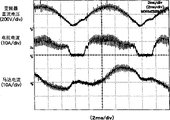
Here, Figure 14~shown in Figure 16 is under various conditions, the result when frequency changer controller of the present invention is moved.Figure 14 is that carrier frequency is 3.3KHz, and Figure 15 is 5KHz, and Figure 16 is the result of the action under the situation of 7.5KHz.As can be seen, compare with the reactive current waveform, reactive current (or AC power electric current) is bigger to the dependence of carrier frequency.
And, measure separately AC power power factor value with digital power meter, be 0.878 when then the carrier frequency of Figure 14 is for 3.3KHz, be 0.956 during the 5KHz of Figure 15, and be 0.962 during the 7.5KHz of Figure 16.
In addition, each element as this moment, the inductance value of low capacity reactance is 0.5mH, the capacity of low capacity electric capacity is 10 μ F, AC power is 220V (50Hz), the frequency converter running frequency is 57Hz (because the number of poles of motor is 2 utmost points, the frequency converter running frequency equates with the motor speed command value here), and the input electric power of AC power is 900W.
Here, such as when predefined AC power power factor is 0.9, carrier frequency is set between 3.3KHz~5KHz gets final product, final one side satisfies predefined AC power power factor (being 0.9) here, simultaneously the lowland of carrier frequency is determined.
As mentioned above, can satisfy predefined AC power power factor value, set the little carrier frequency of trying one's best, therefore the frequency converter loss can be suppressed to minimum.
Embodiment 6
Figure 17 represents to utilize the configuration example of the air regulator of above-mentioned frequency changer controller.As shown in the drawing, air regulator adopts above-mentioned frequency changer controller 100, and on the basis of motor compressor 82, also possesses the refrigerating circulation system that is made of indoor units 92, outdoor unit 95 and cross valve 91.Indoor units 92 is made of indoor blower 93 and indoor heat converter 94, and outdoor unit 95 is made of outdoor heat converter 96, outdoor draft fan 97 and expansion valve 98.
Motor compressor 82 is driven by induction motor 4, and induction motor 4 is driven by frequency changer controller 100.Refrigerant as thermal medium in the refrigerating circulation system circulates.Refrigerant is compressed by motor compressor 82, in outdoor heat converter 96, carry out heat exchange by the wind sent here from outdoor draft fan 97 and outdoor air, and in indoor heat converter 94, carry out heat exchange by the wind sent here from indoor blower 93 and indoor air.
In addition, in the above-described embodiments, induction motor is illustrated, still, obviously the present invention also can be suitable for other motor.
Industrial applicibility
The invention provides the motor driving Frequency Converter Control that a kind of volume is little, in light weight, cost is low Device, the control device that can be used as the motor that air regulator etc. uses uses.
Claims (7)
1. frequency changer controller, this device comprises: the alternating current of AC power is transformed into galvanic rectification circuit, be transformed into frequency with direct current with hope with this rectification circuit, the alternating current of the voltage of wishing also offers the frequency converter of motor, described rectification circuit comprises diode bridge, reactance with the low capacity of the regulation that exchanges input side or direct current outlet side that is connected in described diode bridge, between the dc bus of described frequency converter, the electric capacity of low capacity of the regulation of the regenerated energy that is used to absorb described motor is being set, and it is characterized in that: described frequency changer controller also possesses:
According to the motor voltage value that is applied to described motor that speed value determined of the motor that gives based on the outside, make the motor voltage instruction implementing device of each phase voltage command value of described motor,
Detect the PN voltage check device of the dc voltage value of described frequency converter,
Determine the dc voltage reference value arithmetic unit of the dc voltage reference value of described frequency converter,
Thereby by with described dc voltage reference value divided by described dc voltage detection value derive PN voltage augmenting factor PN voltage compensating device and
By each phase voltage command value that obtained by described motor voltage instruction implementing device and PN voltage augmenting factor as the output valve of described PN voltage compensating device are carried out multiplying, carry out the motor voltage instruction compensating device of the revisal of each phase voltage command value;
Described PN voltage compensating device, have as the mode when described dc voltage value is higher than described dc voltage reference value, used, described PN voltage augmenting factor is set at 1 first mode and described PN voltage augmenting factor directly is set at second mode of the value that described dc voltage reference value obtains divided by described dc voltage detection value.
2. frequency changer controller as claimed in claim 1 is characterized in that: the dc voltage reference value of being determined by described dc voltage reference value arithmetic unit, the motor speed command value that can give corresponding to the outside and changing.
3. frequency changer controller as claimed in claim 1 or 2, it is characterized in that: set described frequency converter running frequency, thereby the resonance frequency of avoiding the frequency converter running frequency to be fixed on the frequency of even-multiple with ac power frequency is the center with being stabilized, has before and after it in frequency range of band width of regulation.
4. frequency changer controller as claimed in claim 1 or 2, it is characterized in that: determine the combination of the electric capacity of the reactance of described low capacity and described low capacity, thereby make the reactance of described low capacity bigger 40 times than ac power frequency with the resonance frequency of the electric capacity of described low capacity.
5. frequency changer controller as claimed in claim 1 or 2, it is characterized in that: determine the capacity of the electric capacity of described low capacity, thus the maximum of the dc voltage value that when described frequency converter stops, rising withstand voltage littler than the electric component in the peripheral circuit that is contained in described frequency converter.
6. frequency changer controller as claimed in claim 1 or 2 is characterized in that: thus the carrier frequency of determining described frequency converter satisfies predefined AC power power factor value.
7. air regulator is characterized in that: possess:
The compressor of compression refrigerant;
Be used to drive the motor of described compressor;
Be used to drive the frequency changer controller as claimed in claim 1 or 2 of described motor.
Applications Claiming Priority (4)
| Application Number | Priority Date | Filing Date | Title |
|---|---|---|---|
| JP2003088439 | 2003-03-27 | ||
| JP2003088439 | 2003-03-27 | ||
| JP2004054287A JP3955285B2 (en) | 2003-03-27 | 2004-02-27 | Inverter control device for motor drive and air conditioner |
| JP2004054287 | 2004-02-27 |
Publications (2)
| Publication Number | Publication Date |
|---|---|
| CN1534859A CN1534859A (en) | 2004-10-06 |
| CN1282301C true CN1282301C (en) | 2006-10-25 |
Family
ID=33455424
Family Applications (1)
| Application Number | Title | Priority Date | Filing Date |
|---|---|---|---|
| CNB2004100314753A Expired - Fee Related CN1282301C (en) | 2003-03-27 | 2004-03-29 | Frequency changer controller for driving motor and air-conditioner |
Country Status (3)
| Country | Link |
|---|---|
| US (1) | US6972541B2 (en) |
| JP (1) | JP3955285B2 (en) |
| CN (1) | CN1282301C (en) |
Cited By (1)
| Publication number | Priority date | Publication date | Assignee | Title |
|---|---|---|---|---|
| CN101873078B (en) * | 2009-04-21 | 2012-11-21 | 比亚迪股份有限公司 | Controllable rectifying device and electromotor using the same |
Families Citing this family (27)
| Publication number | Priority date | Publication date | Assignee | Title |
|---|---|---|---|---|
| WO2004025820A1 (en) * | 2002-09-13 | 2004-03-25 | Tokyo Electron Limited | Rotation drive device and rotation drive method |
| US7207711B2 (en) * | 2002-12-23 | 2007-04-24 | Premark Feg L.L.C. | Mixing device with variable speed drive and related control features |
| US7273315B2 (en) * | 2002-12-23 | 2007-09-25 | Premark Feg Llc | Mixing device with variable speed drive and related control features |
| JP2004289985A (en) * | 2003-03-25 | 2004-10-14 | Matsushita Electric Ind Co Ltd | Inverter controller for driving motor and air conditioner |
| JP3980005B2 (en) * | 2003-03-28 | 2007-09-19 | 松下電器産業株式会社 | Inverter control device for motor drive and air conditioner |
| JP3955286B2 (en) * | 2003-04-03 | 2007-08-08 | 松下電器産業株式会社 | Inverter control device for motor drive and air conditioner |
| JP3955287B2 (en) * | 2003-04-03 | 2007-08-08 | 松下電器産業株式会社 | Inverter control device for motor drive and air conditioner |
| US7395527B2 (en) | 2003-09-30 | 2008-07-01 | International Business Machines Corporation | Method and apparatus for counting instruction execution and data accesses |
| US7415705B2 (en) | 2004-01-14 | 2008-08-19 | International Business Machines Corporation | Autonomic method and apparatus for hardware assist for patching code |
| US7895382B2 (en) | 2004-01-14 | 2011-02-22 | International Business Machines Corporation | Method and apparatus for qualifying collection of performance monitoring events by types of interrupt when interrupt occurs |
| JP4304122B2 (en) * | 2004-05-25 | 2009-07-29 | 三菱電機株式会社 | Electric vehicle control device |
| US7877815B2 (en) * | 2006-01-20 | 2011-01-25 | Kyocera Corporation | Battery authentication in a wireless communication device |
| WO2013136753A1 (en) * | 2012-03-15 | 2013-09-19 | パナソニック株式会社 | Power feed device of inductive charging device |
| WO2013136755A1 (en) * | 2012-03-16 | 2013-09-19 | パナソニック株式会社 | Power feed device of inductive charging device |
| JP5664588B2 (en) * | 2012-04-20 | 2015-02-04 | 株式会社安川電機 | Power regeneration device and power conversion device |
| JP5421433B2 (en) * | 2012-06-25 | 2014-02-19 | ファナック株式会社 | Motor control device that reduces power consumption of control power supply during power outage |
| JP6176121B2 (en) * | 2014-01-10 | 2017-08-09 | 住友電気工業株式会社 | Power converter and three-phase AC power supply |
| JP5742980B1 (en) * | 2014-02-19 | 2015-07-01 | ダイキン工業株式会社 | Power converter control method |
| EP3116120A4 (en) * | 2014-03-05 | 2017-10-18 | Nidec Servo Corporation | Motor system |
| JP6614825B2 (en) * | 2015-06-30 | 2019-12-04 | 日立ジョンソンコントロールズ空調株式会社 | Power conversion device, motor drive device, refrigeration device |
| JP6701637B2 (en) * | 2015-07-21 | 2020-05-27 | ダイキン工業株式会社 | Inverter device |
| US11052360B2 (en) | 2017-02-28 | 2021-07-06 | Illinois Tool Works Inc. | Mixing machine system |
| WO2018160518A1 (en) | 2017-02-28 | 2018-09-07 | Illinois Tool Works Inc. | Mixing machine system |
| GB2573247B (en) | 2017-02-28 | 2022-04-20 | Illinois Tool Works | Mixing machine with VFD based diagnostics |
| GB2583237B (en) | 2017-12-21 | 2022-06-15 | Illinois Tool Works | Mixing machine |
| CN108809073B (en) * | 2018-05-31 | 2020-01-17 | 奥克斯空调股份有限公司 | APFC circuit voltage control method and system and air conditioner |
| WO2022172505A1 (en) * | 2021-02-10 | 2022-08-18 | パナソニックIpマネジメント株式会社 | Electric motor driving device |
Family Cites Families (19)
| Publication number | Priority date | Publication date | Assignee | Title |
|---|---|---|---|---|
| US4992718A (en) * | 1989-09-11 | 1991-02-12 | Nihon Patent Electric Co., Ltd. | Electric floor cleaner with a soft start function |
| JPH03155392A (en) * | 1989-11-10 | 1991-07-03 | Toshiba Corp | Current detecting unit |
| US6002218A (en) * | 1992-11-20 | 1999-12-14 | Fujitsu General Limited | Control device for air conditioner |
| US5457375A (en) * | 1994-05-27 | 1995-10-10 | Emerson Electric Co. | Sensorless commutation controller for a poly-phase dynamoelectric machine |
| US5561595A (en) * | 1995-03-24 | 1996-10-01 | Magl Power Inc. | Power inverter with input line conditioning |
| JP3519540B2 (en) | 1996-03-28 | 2004-04-19 | 東芝キヤリア株式会社 | DC power supply and air conditioner |
| DE69914242T2 (en) * | 1998-03-23 | 2004-11-04 | Hitachi, Ltd. | Control device for a brushless motor and machine with a brushless motor |
| JP4154679B2 (en) * | 1998-04-18 | 2008-09-24 | 株式会社安川電機 | Electric motor power failure processing method and control device therefor |
| US6229278B1 (en) * | 1999-09-29 | 2001-05-08 | Rockwell Technologies, Llc | Voltage and current limiting method and apparatus for a voltage/frequency drive |
| US6489692B1 (en) * | 1999-12-13 | 2002-12-03 | Capstone Turbine Corporation | Method and apparatus for controlling rotation of magnetic rotor |
| US6414455B1 (en) * | 2000-04-03 | 2002-07-02 | Alvin J. Watson | System and method for variable drive pump control |
| JP4465129B2 (en) * | 2000-07-14 | 2010-05-19 | パナソニック株式会社 | Brushless motor driving apparatus and driving method |
| EP1492223A4 (en) * | 2002-03-22 | 2005-12-14 | Matsushita Electric Ind Co Ltd | Synchronous reluctance motor control device |
| EP1429450B1 (en) * | 2002-12-12 | 2008-02-13 | Matsushita Electric Industrial Co., Ltd. | Motor control apparatus |
| JP2004289985A (en) * | 2003-03-25 | 2004-10-14 | Matsushita Electric Ind Co Ltd | Inverter controller for driving motor and air conditioner |
| JP3980005B2 (en) * | 2003-03-28 | 2007-09-19 | 松下電器産業株式会社 | Inverter control device for motor drive and air conditioner |
| JP3955287B2 (en) * | 2003-04-03 | 2007-08-08 | 松下電器産業株式会社 | Inverter control device for motor drive and air conditioner |
| JP2004350493A (en) * | 2003-04-28 | 2004-12-09 | Matsushita Electric Ind Co Ltd | Inverter controller for driving motor and air conditioner using the same |
| US7078876B2 (en) * | 2003-07-07 | 2006-07-18 | Pentadyne Power Corporation | Feedforward controller for synchronous reluctance machines |
-
2004
- 2004-02-27 JP JP2004054287A patent/JP3955285B2/en not_active Expired - Fee Related
- 2004-03-26 US US10/809,485 patent/US6972541B2/en not_active Expired - Lifetime
- 2004-03-29 CN CNB2004100314753A patent/CN1282301C/en not_active Expired - Fee Related
Cited By (1)
| Publication number | Priority date | Publication date | Assignee | Title |
|---|---|---|---|---|
| CN101873078B (en) * | 2009-04-21 | 2012-11-21 | 比亚迪股份有限公司 | Controllable rectifying device and electromotor using the same |
Also Published As
| Publication number | Publication date |
|---|---|
| US6972541B2 (en) | 2005-12-06 |
| US20040232876A1 (en) | 2004-11-25 |
| JP3955285B2 (en) | 2007-08-08 |
| JP2004312990A (en) | 2004-11-04 |
| CN1534859A (en) | 2004-10-06 |
Similar Documents
| Publication | Publication Date | Title |
|---|---|---|
| CN1282301C (en) | Frequency changer controller for driving motor and air-conditioner | |
| CN1311621C (en) | Frequency changer controller for driving motor and air-conditioner | |
| CN1543047A (en) | Inverter controller for driving motor, and air conditioner | |
| CN1538611A (en) | Converter controller of drive motor and air conditioner using converter controller | |
| CN1229605C (en) | Frequency conversion air conditioner | |
| CN1181992C (en) | Device for controlling internal combustion engine type electric locomotive | |
| CN1265093C (en) | Control driving device and method for reciprocating compressor using linear motor refrigerator | |
| CN1081244A (en) | The control method of air conditioner | |
| CN1677815A (en) | Reversible back-boost chopper circuit, and inverter circuit with the same | |
| CN1649248A (en) | Inverter controlling apparatus for driving a motor and an air conditioner using same | |
| CN1959583A (en) | Power source apparatus | |
| CN101039081A (en) | Apparatus and method for supplying DC power source | |
| CN101039079A (en) | Apparatus and method for supplying DC power source | |
| CN1180956A (en) | Motor control apparatus, and motor drive apparatus and air-condictioner | |
| CN101064483A (en) | Device and method for controlling power converting device | |
| CN1320297A (en) | Controller for PWM/PAM motor and method for controlling air conditioner and motor having controller | |
| CN1574582A (en) | Soft switch power converter | |
| CN1830133A (en) | Voltage conversion device and computer-readable recording medium having program recorded thereon for computer to control voltage conversion | |
| CN1306232C (en) | Gas heat pump type air conditioner | |
| CN103580469B (en) | A kind of power factor correcting method for permagnetic synchronous motor | |
| JP4340518B2 (en) | Load drive device | |
| CN2589870Y (en) | Frequency conversion air-conditioner | |
| JP2017112776A (en) | Converter device, drive control device, motor, and compressor | |
| CN1703826A (en) | Motor control method and device thereof | |
| CN1728542A (en) | Control process and control device of induction motor ind. appts. |
Legal Events
| Date | Code | Title | Description |
|---|---|---|---|
| C06 | Publication | ||
| PB01 | Publication | ||
| C10 | Entry into substantive examination | ||
| SE01 | Entry into force of request for substantive examination | ||
| C14 | Grant of patent or utility model | ||
| GR01 | Patent grant | ||
| C17 | Cessation of patent right | ||
| CF01 | Termination of patent right due to non-payment of annual fee |
Granted publication date: 20061025 Termination date: 20140329 |