JP3948757B2 - Silicate long afterglow luminescent material and method for producing the same - Google Patents
Silicate long afterglow luminescent material and method for producing the same Download PDFInfo
- Publication number
- JP3948757B2 JP3948757B2 JP54439998A JP54439998A JP3948757B2 JP 3948757 B2 JP3948757 B2 JP 3948757B2 JP 54439998 A JP54439998 A JP 54439998A JP 54439998 A JP54439998 A JP 54439998A JP 3948757 B2 JP3948757 B2 JP 3948757B2
- Authority
- JP
- Japan
- Prior art keywords
- afterglow
- long afterglow
- emission
- luminescent material
- green
- Prior art date
- Legal status (The legal status is an assumption and is not a legal conclusion. Google has not performed a legal analysis and makes no representation as to the accuracy of the status listed.)
- Expired - Lifetime
Links
Images


Classifications
-
- C—CHEMISTRY; METALLURGY
- C09—DYES; PAINTS; POLISHES; NATURAL RESINS; ADHESIVES; COMPOSITIONS NOT OTHERWISE PROVIDED FOR; APPLICATIONS OF MATERIALS NOT OTHERWISE PROVIDED FOR
- C09K—MATERIALS FOR MISCELLANEOUS APPLICATIONS, NOT PROVIDED FOR ELSEWHERE
- C09K11/00—Luminescent, e.g. electroluminescent, chemiluminescent materials
- C09K11/08—Luminescent, e.g. electroluminescent, chemiluminescent materials containing inorganic luminescent materials
- C09K11/77—Luminescent, e.g. electroluminescent, chemiluminescent materials containing inorganic luminescent materials containing rare earth metals
- C09K11/7783—Luminescent, e.g. electroluminescent, chemiluminescent materials containing inorganic luminescent materials containing rare earth metals containing two or more rare earth metals one of which being europium
- C09K11/7797—Borates
-
- C—CHEMISTRY; METALLURGY
- C09—DYES; PAINTS; POLISHES; NATURAL RESINS; ADHESIVES; COMPOSITIONS NOT OTHERWISE PROVIDED FOR; APPLICATIONS OF MATERIALS NOT OTHERWISE PROVIDED FOR
- C09K—MATERIALS FOR MISCELLANEOUS APPLICATIONS, NOT PROVIDED FOR ELSEWHERE
- C09K11/00—Luminescent, e.g. electroluminescent, chemiluminescent materials
- C09K11/08—Luminescent, e.g. electroluminescent, chemiluminescent materials containing inorganic luminescent materials
- C09K11/77—Luminescent, e.g. electroluminescent, chemiluminescent materials containing inorganic luminescent materials containing rare earth metals
- C09K11/7728—Luminescent, e.g. electroluminescent, chemiluminescent materials containing inorganic luminescent materials containing rare earth metals containing europium
- C09K11/77342—Silicates
-
- C—CHEMISTRY; METALLURGY
- C09—DYES; PAINTS; POLISHES; NATURAL RESINS; ADHESIVES; COMPOSITIONS NOT OTHERWISE PROVIDED FOR; APPLICATIONS OF MATERIALS NOT OTHERWISE PROVIDED FOR
- C09K—MATERIALS FOR MISCELLANEOUS APPLICATIONS, NOT PROVIDED FOR ELSEWHERE
- C09K11/00—Luminescent, e.g. electroluminescent, chemiluminescent materials
- C09K11/08—Luminescent, e.g. electroluminescent, chemiluminescent materials containing inorganic luminescent materials
- C09K11/77—Luminescent, e.g. electroluminescent, chemiluminescent materials containing inorganic luminescent materials containing rare earth metals
- C09K11/7728—Luminescent, e.g. electroluminescent, chemiluminescent materials containing inorganic luminescent materials containing rare earth metals containing europium
- C09K11/7737—Phosphates
- C09K11/7738—Phosphates with alkaline earth metals
-
- C—CHEMISTRY; METALLURGY
- C09—DYES; PAINTS; POLISHES; NATURAL RESINS; ADHESIVES; COMPOSITIONS NOT OTHERWISE PROVIDED FOR; APPLICATIONS OF MATERIALS NOT OTHERWISE PROVIDED FOR
- C09K—MATERIALS FOR MISCELLANEOUS APPLICATIONS, NOT PROVIDED FOR ELSEWHERE
- C09K11/00—Luminescent, e.g. electroluminescent, chemiluminescent materials
- C09K11/08—Luminescent, e.g. electroluminescent, chemiluminescent materials containing inorganic luminescent materials
- C09K11/77—Luminescent, e.g. electroluminescent, chemiluminescent materials containing inorganic luminescent materials containing rare earth metals
- C09K11/7728—Luminescent, e.g. electroluminescent, chemiluminescent materials containing inorganic luminescent materials containing rare earth metals containing europium
- C09K11/774—Borates
-
- C—CHEMISTRY; METALLURGY
- C09—DYES; PAINTS; POLISHES; NATURAL RESINS; ADHESIVES; COMPOSITIONS NOT OTHERWISE PROVIDED FOR; APPLICATIONS OF MATERIALS NOT OTHERWISE PROVIDED FOR
- C09K—MATERIALS FOR MISCELLANEOUS APPLICATIONS, NOT PROVIDED FOR ELSEWHERE
- C09K11/00—Luminescent, e.g. electroluminescent, chemiluminescent materials
- C09K11/08—Luminescent, e.g. electroluminescent, chemiluminescent materials containing inorganic luminescent materials
- C09K11/77—Luminescent, e.g. electroluminescent, chemiluminescent materials containing inorganic luminescent materials containing rare earth metals
- C09K11/7783—Luminescent, e.g. electroluminescent, chemiluminescent materials containing inorganic luminescent materials containing rare earth metals containing two or more rare earth metals one of which being europium
- C09K11/77922—Silicates
-
- C—CHEMISTRY; METALLURGY
- C09—DYES; PAINTS; POLISHES; NATURAL RESINS; ADHESIVES; COMPOSITIONS NOT OTHERWISE PROVIDED FOR; APPLICATIONS OF MATERIALS NOT OTHERWISE PROVIDED FOR
- C09K—MATERIALS FOR MISCELLANEOUS APPLICATIONS, NOT PROVIDED FOR ELSEWHERE
- C09K11/00—Luminescent, e.g. electroluminescent, chemiluminescent materials
- C09K11/08—Luminescent, e.g. electroluminescent, chemiluminescent materials containing inorganic luminescent materials
- C09K11/77—Luminescent, e.g. electroluminescent, chemiluminescent materials containing inorganic luminescent materials containing rare earth metals
- C09K11/7783—Luminescent, e.g. electroluminescent, chemiluminescent materials containing inorganic luminescent materials containing rare earth metals containing two or more rare earth metals one of which being europium
- C09K11/7795—Phosphates
- C09K11/7796—Phosphates with alkaline earth metals
Abstract
Description
技術分野
本発明は長残光の発光材料にかかわり、特にケイ酸塩長残光の発光材料とその製造方法にかかわる。
背景技術
伝統的なZnS系列の長残光の発光材料は19世紀に発明して以来、絶えずに改良されたため、すでにいくつかの典型的な産品が形成されており、例えば:ZnS:Cu(緑色発光)、(CaSr)S:Bi(青色発光)(ZnCd)S:Cu(黄橙発光)であり、そしていくつかの商業分野に応用されている。ただし、この種の材料の欠陥は安定性が悪く、空気中で分解しやすく、陽光の下で黒くなりやすく、且つ残光の発光時間が短く、普通0.5-2時間以内にあり、且つ発光光度がやや低めであるため、実際の要求には満足できない。材料の発光光度を高め、残光輝度の時間を伸ばすために、人々は前後これらの材料の中にCo、Ra、H3等の放射性元素を添加して、放射発光の残光輝度時間の長い材料を作り上げた。しかし、材料を持続発光させ、さらに航空ゲージ、時計などの分野に応用されたが、放射性の汚染且つ価格が高すぎたので、使用範囲はおおいに制限されている。
90年代の始めに、アルミ酸塩系列の長残光の発光材料が発明されており、例えば、中国特許公開番号CN1053807Aと中国特許ZL92110744.7で示されたとおりである。その発光強度、長残光の性能、安定性はともに上述の硫化系列商品よりすぐれており、そして生活用品、弱照明指示標識看板、時計などの分野に応用されている。ただし、これらの材料にはなお耐水性が悪く、原材料の純度、形態に対しての要求が厳しく、生産コストも高いし、さらに発光色が単一等の欠陥があるため、ある程度に長残光の発光材料の要求に対してよく応じることができない。
1968年T.L.BarryはかつてMe3MgSi2O8:Eu2+(Me=Ca、Sr、Ba)とMe2SiO4:Eu2+(Me=Sr、Ba)の発光スペクトルと励起スペクトルに関する研究結果(J.Electrochem.Soc.V115 No.7,733-738,1968年;V115 No.11,1181-1184,1968年)を発表した。その後、T.L.BarryはまたBaMg2Si2O7:Eu2+の発光と励起スペクトルに関する研究結果(J.Electrochem Soc.V117 No.3,381-385,1970年)を発表した。1968年にBlasse,G.などはFluorescence of Eu2+activated silicates(Philips Res.Rep.(1968),23(2),189-200)を発表してから今日にいたる。今までわりに強い長残光性能のケイ酸塩材料に関する報道がまだ見つかっていない。
発明の開示
本発明は上記の欠点を解消し、色が多様で、スペクトル範囲が広く、安定で耐水性に優れた残光度が高い且つ時間が長い珪酸系の長残光の発光材料を提供しようとするものである。
本発明は、アルミ酸塩体系の長残光の発光材料に継いでのち、新型体系の長残光の発光材料であり、これがケイ酸塩を基質に、希土イオンとその他イオンを賦活剤にし、さらに一定量のホウ素又はリンなどの化合物を入れ、これで長残光の性能を高める長残光の発光材料を促成させ、ケイ酸塩系の中で青、緑、黄など多色の長残光の発光特性を実現させた。
本発明は、長残光の発光材料の主な化学組成は式(1)で表示され:
aMO・bM’O・cSiO2・dR:Eux、Lny (1)
その中、Mはストロンチウム(Sr)、カルシウム(Ca)バリウム(Ba)、亜鉛(Zn)の中から一種又は多種元素を選ばれる;M’はマグネシウム(Mg)、カドミウム(Cd)、ベリリウム(Be)の中から一種又は多種元素を選ばれる;RはB2O3、P2O5の中から一種又は多種の成分を選ばれる;Lnはネオジム(Nd)、ジスプロシウム(Dy)、ホルミウム(Ho)、ツリウム(Tm)、ランタン(La)、プラセオジム(Pr)、テルビウム(Tb)、セリウム(Ce)、マンガン(Mn)、ビスマス(Bi)、スズ(Sn)、アンチモン(Sb)の中から一種あるいは多種を選ばれる;a、b、c、d、x、yはモル係数であり、その中:0.6≦a≦6,0≦b≦5,1≦c≦9,0≦d≦0.7,0.00001≦x≦0.2,0≦y≦0.3である;その材料は500nm以下の短波光の励起によって、420−650nmの発射スペクトルを出し、ピーク値は450−580nmであり、青、青緑、緑、緑黄などの長残光の発光色を現す。
本発明によるよく選ばれた長残光の発光材料はその式(1)の中のMはSr、Caの中から一種または多種の元素を選ばれる;M’はMgである;LnはNd、Dy、Ho、Bi、Snの中から一種または多種元素を選ばれ、そのうち:0.6≦a≦4,0.6≦b≦4,1≦c≦5,0<d≦0.4であり、RはB2O3、P2O5の中から一種または多種成分を選ばれる。
本発明における一種の長残光の発光材料によると、そのうち材料の主な結晶体構造は:M2MgSi2O7あるいはM3MgSi2O8であり、そのうちMはSr1-zCaz0≦z≦1である。
本発明における一種の長残光の発光材料によると、そのうち材料の主な化学構造は式で表示されると:M2MgSi2O7:M3MgSi2O8:Eu、Lnとし、そのうちMはSr1-zCaz,0≦z≦1である。
本発明の長残光の発光材料を製造したとき、式(1)の中の元素を含まれる化合物を使い、一般に選択しようされた原料のうち、M、M’、Ln、Euの化合物はそれぞれそれらの代表元素の炭酸塩、硫酸塩、硝酸塩、リン酸塩、ホウ酸塩、酢酸塩、シュウ酸塩、レモン酸塩またはその酸化物、水素酸化物、ハロゲン下化物などを使う。Siの化合物はSiO2、ケイ酸、シリカゲルまたはケイ酸塩などを使い、Rはホウ素、リンなどの化合物を使い、使われた原料中のモルの比率は:
M:6〜6R:0〜0.7 B2O3、P2O5をもって計
M’:0〜5 Eu:0.00001〜0.2
Si:1〜9 Ln:0〜0.3
そのうち:MはSr、Ca、Ba、Znの中の一種または多種元素の化合物を示す;
M’はMg、Cd、Beの中の一種或は多種元素の化合物を示す;
RはB、Pの中の一種或は二種元素の化合物を示す;
LnはNd、Dy、Ho、Tm、La、Pr、Tb、Ce、Mn、Bi、Sn、Sbの中の一種或は多種元素の化合物を示す;
SiはSiの化合物を示す;
EuはEu化合物を示す。
その製造は高温固相反応法を採用し製造したのであり、上記の原料をモル比率によって取り、細かく磨きさらによく混合し、混合する場合、乾燥法を使ってもいいし、溶剤(例えば、アルコール、アセトンなど)を入れるが良い。混合後、乾燥させ、又は化学反応のゾル−凝固した粘着剤法を使い、混合物料を作り、それをつるぼの容器の中に充填してから、高温炉の中に入れる。還元の雰囲気の下(例えば、水素(H2)アンモニア(NH3)窒素と水素(N2+H2)、炭素粒(C粒))などが、1100−1400℃にあり、炉の容量と物量の重量によって、2〜50時間で焼成し、一般に小量物量例えば:NH4Cl、NH4F、CaF2、SrF2、Li2CO3、CaSO4、SrSO4、SrHPO4、CaHPO4などである。焼成後、冷却、粉砕し篩分プロセス等を経てから使用要求に基づいて、各級粒の材料に篩分する。
【図面の簡単な説明】
図1でSr2MgSi2O7:Euの材料の発光スペクトル(a)と励起スペクトル(b)を示す。
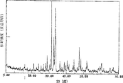
図2でSr2MgSi2O7:Euの材料のX−線回折譜図を示す。
図3でSr2MgMSi2O7:Eu、Dy材料の発光スペクトル(a)と励起スペクトル(b)を示す。
図4でSr2MgSi2O7:Eu、Dy材料の残光輝度特性曲線を示す。
図5でCa2MgSi2O7:Eu、Dy発光スペクトル(a)と励起スペクトル(b)を示す。
図6でCa2MgSi2O7:Eu、Dy材料のX−線回折譜図を示す。
図7でCa2MgSi2O7:Eu、Dy材料の残光輝度特性曲線を示す。
図8で(Sr0.5Ca0.5)2MgSi2O7:Eu、Dy材料の発光スペクトル(a)と励起スペクトル(b)を示す。
図9で(Sr0.5Ca0.5)2MgSi2O7:Eu、Dy材料のX−線回折譜図を示す。
図10で(Sr0.5Ca0.5)2MgSi2O7:Eu、Dy材料の残光輝度特性曲線を示す。
図11で(Sr0.75Ca0.25)2MgSi2O7:Eu、Dy材料の発光スペクトル(a)と励起スペクトル(b)を示す。
図12で(Sr0.25Ca0.75)2MgSi2O7、Eu、Dy材料の発光スペクトル(a)と励起スペクトル(b)を示す。
図13でSr3MgSi2O8:Eu、Dy材料の発光スペクトル(a)と励起スペクトル(b)を示す。
図14でSr3MgSi2O8:Eu、Dy材料のX−線回折譜図をを示す。
図15でCa3MgSi2O8:Eu、Dy材料の発光スペクトル(a)と励起スペクトル(b)を示す。
図16でCa3MgSi2O8:Eu、Dy材料のX−線回折図をを示す。
図17でBa5Si8O21:Eu、Dy材料の発光スペクトル(a)と励起スペクトル(b)を示す。
発明を実施するための最良の形態
本発明は見本に対してその残光輝度を計る方法は見本を直径50mm、深さは5mmの円盤の中におき、暗室において10時間以上にしてからそれを取出し、基準としてD65光源1000Lxの下に置いて、照射10分間後、発光輝度でその時間の推移につれて変化していく発光強度を測る。測る同時に、現有の技術の比較、見本を同一条件の下で励起させ、比較する見本は100、見本の相対輝度の強度を求める。青色輝度の比較見本は(CaSr)S:Bi;黄色輝度の比較見本は(ZnCd)S:Cu;緑、青緑、緑黄輝度の比較見本はZnS:Cu。材料の結晶体構造はX−線回折方式で測り、そのX−線回折譜図を測り、更にカード値を見合わせて、その主要結晶体の構造を定める。材料の発光スペクトルと励起スペクトルは蛍光スペクトルゲージで測る。
大量の研究の結果によると、化学組成表示式(1)で、M、M’の中の元素が違えば、材料の長残光の発光色も違うし、材料の主要な結晶体構造も違う:a、b、c数値の変化は材料の発光強度、結晶体構造と発光色に対して一定の影響を与える。RとLnの中の異なる元素の成分及び係数d、x、yの数値変化は発光強度に対して明らかな影響を与えるが、しかし主要結晶体構造にそんなに大きな影響を与えていないようである。
表1は材料の発光色とM、M’及びa、bの関連部分の試験結果を出されている。
表1の試験条件は表示式のc=2.5,d=0.1,R=B2O3,x=0.005,y=0.04,Ln=Nd,還元雰囲気はN2(90%)+H2(10%)を選び、合成温度は1250−1320℃で時間は4時間とする。

MはCaを代表し、またはCaをその中の主要元素にし、Sr、Ba、Znは副次的な元素にし、M’はMgを代表し、またはMgをその中の主要元素にして、Cd、Beは副次的な元素にするとき、合成的な材料は500nmいかの短波の照射後、緑−黄色長残光の発光色が現れている。同様な実験によると、a、b、cの異なる数値は材料の発光強度に一定の影響を与える。0.6≦a≦4,0.6≦b≦4,1≦c≦5のとき材料がわりに強い緑−黄色の発光が現れており、1.5≦a≦2.4,0.6≦b≦2,1.5≦c≦2.5の場合、X−線回折データで材料の主要な結晶体構造を分析してみるCa2MgSi2O7の結晶体構造であると知られ、図6で示すように。上記の係数範囲を越える場合、材料にもCa2MgSi2O7の結晶体構造が現れたが、その他の結晶体構造の成分がわりに多い;2.7≦a≦3.3,0.8≦b≦1.2,1.7≦c≦2.3とき、材料の主要結晶体構造はCa3MgSi2O8であると知られ、図16で示すように。
MはSr、または/Caを代表して、便宜上、Sr1-zCazの式で示す。そのうち、0≦z≦1、またはSr1-zCazをその中の主要元素にし、Ba、Znを副次的な元素にするとき、M’はMgを代表し、またはMgを主要元素にし、Cd、Beを副次的な元素にするとき、合成的な材料はZ値につれて変化して、青−青緑−緑黄−黄色と長残光の発光色の変化があらわれる。z=0青色となり、z=1は緑−黄色隣、0<z<0.5青緑−緑となり0.5<z<1は主に緑−緑黄色となり、Z=0.5またはその付近のところは緑色となる。同様、a、b、cの異なる数値は材料の発光強度と構造に一定の影響を与える。0.6≦a≦4,0.6≦b≦4,1≦c≦5,材料がわりに強い青緑−緑−緑黄の発光色が現れており、1.5≦a≦2.4,0.6≦b≦2,1.5≦c≦2.5の場合、材料の主要な結晶体構造はX−線回折データから分析してみると、その回折譜図と上記のSr2MgSi2O7とCa2MgSi2O7譜図にかなり近似しており、表示式での比率を参考し、(Sr1-zCaz)2MgSi2O7結晶体構造であると推測することができ、図9で示すように;上記の係数の範囲を越えるとき、材料中にも(Sr1-zCaz)2MgSi2O7結晶体構造が現れることができるが、その他の結晶体構造成分がわりに多い。
発光学の関連資料の表示式を参照したところ、材料の結晶体構造はまた確定できていない場合、その材料の主要成分で示し、即ち、化学組成表示式で示す;その材料の主要な結晶体構造が確定されてから、化学構造表示式で示す。
上記の材料の結晶体構造によると、本発明はこれらの材料の主要化学構造表示式はM2MgSi2O7:Eu、LnまたはM3MgSi2O8:Eu、Ln,その内MはSr1-zCaz,0≦z≦1。
MはBaを代表し、4≦a≦6,b=0,6≦c≦9となると、材料が浅緑色長残光の発光色が現れており、X−線回折データから分析してみると、主要結晶体構造はBa5Si8O21である。本発明のこれらの材料の主要化学構造表示式はBa5Si8O21:Eu、Lnとなる。
MはZnを代表し、1≦a≦3,b=0,0.7≦c≦1.5となり、材料には浅緑色長残光の発光色が現れており、X−線回折データから分析してみると、主要結晶構造はZn2SiO4である。本発明のこれらの材料の主要化学構造表示式はZn2SiO4:Eu、Lnとなる。
MはSr1-zCaz,0≦z≦1を代表し、M’はMgを代表し、そのうちM、M’の0−40%モルはBa、Zn、Cd、Beに取って代られ、材料には長残光の発光性能を有し、特にBa、Cdは5−20%モルに取ってかわるとき、材料には良好な発光性能を有する。
化学組成表示式の中で、Rと/またはLn元素(即ちdまたは/とyが0となるとき)による合成した材料がなくても残光を発することができ、ある組合わせにはわりに強い残光の発光を持つ。しかし、材料中にはRと/またはLnを有すれば、その残光の発光強度は著しく増強しており、当然そのモル係数dとyが違うので、残光の発光強度に一定の影響を与える事ができる。Lnの中の緒元素の加入により、元素が違うので、発光強度も違う。二つ以上の複合元素の混じ入りのほうが単一元素の加入より残光効果がもっと顕著である。
y=0、材料の化学組成表示式はaMO・bM’O・cSiO2・dR:EUxとなり、ユーロピウム(Eu)は賦活剤となる場合、材料のスペクトルから分析してみると、その材料の発光スペクトルはユーロピウム(Eu2+)の特徴発光スペクトルである。即ちユーロピウム(Eu)は主要な賦活剤であり、x数値によって違い、その長残光の発光強度が異なる変化が現れており、xの理想範囲は:0.00001≦x≦0.2。
y>0となるとき、材料中にLn成分を増やす。実験によると、Ln成分中のNd、Dy、Ho、Tm、La、Pr、Tb、Ce、Mn、Bi、Sn、Sbの一種又は数種が存在しており、材料の長残光の発光強度にたいして、、ある程度の増強効果を与え、特にNd、Dy、Ho、Bi、Snの効果が顕著である。実験によると、0<y≦0.3となるとき、材料にたいして、明らかな増強効果を有し、表2−10の試験で示すように、発光学理論によって、共賦活剤の役割を果たすことができる。
d=0となる時、材料の化学組成表示式はaMO・bM’O・cSiO2・dR:Eux、Lnyの材料が一定の長残光の発光効果が現れており、x、y値によって変わり、材料の長残光の発光強度にも一定の変化が現れている。
d>0となる時、R成分の加入によって、材料の長残光の発光強度を相対させ、d=0となり、顕著に高まっており、d成分の原料はホウ素(B)またはリン(P)の化合物でもいいし、例えば、三酸化二ホウ素(B2O3)、ホウ酸(H3BO3)、五酸化二リン(P2O5)、リン酸(H3PO4)、リン酸水素二アンモニウム((NH4)2H2PO4)、リン酸二水素アンモニウム(NH4H2PO4)などである。これらの成分の加入によって、材料の長残光の発光強度を高める;材料の合成温度を低くさせ、材料の合成品質を改善させ、合成材料粉体がやわらかになるため、完成品率も高い。
Rの成分は材料の発光強度に与える影響は表2を御参照。
表2の試験は青緑色材料を選び、M=Sr0.75Ca0.25,M’=Mg,R=B2O3またはとP2O5,Ln=Dy,a=1.5,b=1.5,c=2,5,x=0.01,y=0.08還元雰囲気はNH3であり、合成温度は1280℃となる。
表3の試験は青色と緑色の材料を選び、そのうち、1−8青色材料を実験した時、M=Sr,M’=Mg,a=2,b=1,c=2,x=0.004,R=B2O3とし、試験9−14を試験した時、緑色材料を使い、そのうちM=Sr0.5Ca0.5,M’=Mg,a=2,b=1,c=2.3,R=P2O5,Ln=Dy,x=0.004,y=0.01
次は部分の試験を参考しながら、本発明の材料を述べる:
(一)青色長残光の発光材料
M=Sr,M’=Mg,R=B2O3,a=2,b=1,c=2,d=0.1となる時、材料の化学組成表示式は:2SrO・MgO・2SiO2・0.1B2O3:EUxLny,X価、Lnの元素及びy値を換え、その試験成果は表4で示すように。
1. もし化学組成表示式中でy=0,即ちLnイオンが存在せず、Euの加入量は残光の効果に一定の影響を与えることができ、表4中試験1−1〜7で示すように。比較見本(CaSr)S:Biと比べれば、当材料は一定の長残光の発光効果が現われている、さらに実験を行なったところ、Euのモル量xは0.00001より小さく、0.2より大きいとする場合、その発光効果がやや悪いため、0.00001≦X≦0.2に限定される。
2. x=0.004,Ln=Ndとすると、加入量yの変化対応の残光効果は表4での試験2−1〜6を参照。加入量yは0.0001≦y≦0.3でいい、これで残光強度は明らかに試験1−1〜7より高い、これはNdの加入によって、材料の発光性能を強めたと見られる。試験2−4の材料の残光輝度は時間の変化にともない、残光輝度の二重対数特性曲線を作図する、その曲線は基本的に一本の直線であり、人の目の最小可視光度の0.32mcd/m2の時間は20時間以上に達する。
3. x=0.004、Ln=Dyとすると、加入量yの変化が残光効果、表4での試験3−1〜7を参照、加入量は0.0001≦y≦0.3でいい、そこから残光強度は試験1−1〜7よりあきらかに高いと見られ、これはDyの加入が材料の発光性能を強めたと見られる。試験3−4の残光輝度は時間の変化にともない、残光輝度の二重対数特性曲線を作図する、当曲線が基本的に一本の直線であり、表4で示すように人の目の最小可視光度の時間は35時間以上に達する。
4. x=0.004,LnはそれぞれがHo、Tm、La、Pr、Tb、Ce、Mn、Bi、Sb、Snおよび二つの元素Nd、Dy;Nd、Sn;Dy;Bi,その加入量y対応の残光効果はそれぞれ表4の試験4〜16をご参照
上記の結果から見ると、この種の材料の残光強度は対比材料よりあきらかにすぐれている。とくにNd、Dy、Ho、Bi、Snを加入したあとの効果がもっと顕著である。上記の材料の結晶体構造に基づいて、その青色系の材料の化学構造表示は式Sr2MgSi2O7:Eu、Lnとなる。
(二)黄色長残光の発光材料
M=Ca,M=Mg,R=B2O3,a=2,b=1,c=2,d=0.15の場合、材料の化学組成表示式は2CaO・MgO・2SiO2・O.15B2O3:Eux、Lny,x値、Ln元素およびy値を変えてみると、その試験結果は表5で示すように。
表5は別紙をご参考。
1. 化学組成表示式中でy=0,Euの加入量は残光強度に一定の影響を与え表5の試験1−1〜7で示すように。
2. x=0.004,Ln=Dyとなるとき、加入量yの変化が残光強度にたいする影響は表5での2−1〜4で示すように。そこからDyの加入によって、材料の発光性能を強め、実験の結果からDy加入量は0.0001≦y≦0.2でよいと知られ、図7は試験2−3材料の残光輝度は時間の変化にともなった二重対数特性曲線である。
3. x=0.004,となる時、LnはそれぞれがNd、Ho、Tm、Co、Sn、Bi及び二つの元素Dy、Nd;Dy、Biであり、加入量と残光強度がそれぞれに表5の試験3−10で示すように、その発光残光強度は対比材料よりあきらかにすぐれていることがわかる。
上記の材料の結晶体構造に基づいて、当黄色系材料の化学構造表示式はCa2MgSi2O7:Eu、Lnとなる。
(三)緑色長残光の発光材料
M=Sr0.5Ca0.5,M’=Mg,R=B2O3,a=2,b=1,c=2,d=0.05の場合、材料の化学組成表示式は2(Sr0.5Ca0.5)O・MgO2・SiO2・0.05B2O3:Eux、Lnyとなる。x値、Ln元素およびy値を変えてみると、その試験結果は表6で示すように。
1. 化学組成表示式y=0となるとき、Euの加入量は残光強度に対して一定の影響がある、表6での試験1−1〜6をご参照。
2. x=0.005,Ln=Dyとなる場合、加入量yの変化は残光強度に対して一定の影響がある。表6での試験2−1〜6をご参照。そこから当材料が1−1〜6材料と比較すれば、その残光強度はあきらかに増強することが確認された。図10は試験2−5材料の残光輝度は時間にともなった二重対数特性曲線であり、人の目の最小識別輝度0.32mcd/m2に達し、時間は50時間以上である。
3. x=0.005,Ln=Ndとなるとき、加入量yの変化は残光強度に対して一定の影響がある。表6での試験3−1〜3をご参照。そこから残光強度にもかなり高いし、残光時間も長い。
4. x=0.005,LnはHo、Tm、Ce、Sn、Tb、Pr、Biとすれば、その加入量が残光強度への影響は表6の試験4−10をご参照。
5. x=0.005,Ln=DyとBiとすれば、その同時に加入のは残光強度をおおいに増強させることがわかり、表6の試験11をご参照。
上記の材料の結晶体の構造に基づいて、当緑色系の材料の化学構造表示式(Sr0.5Ca0.5)2MgSi2O7:Eu、Lnとする。
(四)青緑色−緑黄色長残光の発光材料
M=Sr1-zCaz,M’=Mg,R=B2O3,a=2,b=1,c=2,d=0.1のとき、材料の化学組成表示式は2(Sr1-zCaz)O・MgO・2SiO2・0.1B2O3:Eux、Lny、0≦z≦1となると、z値によって違うが、その材料の残光の発光色が違うため、z=0となると、青色になる;z=1となると、黄色になる;z=0.5となると、緑色になる。z値が0から1への変化につれて、SrとCaの比例を変え、材料の残光の発光色にも青から緑へさらに黄色への変化していく。
1. 表7で述べられている2(Sr1-zCaz)O・MgO・2SiO2・0.1B2O3:Eu0.004、Dy0.02かで、試験SrとCaの比例変化が発射スペクトルのピーク値へ影響を与え、そこから、z値が0〜1の変化につれて、発射スペクトルのピーク値が469nmから535nmへ残光の発光色が青、青緑、緑、緑黄、黄のほうへ変化していくことが見られる。表7で示すように。
3. z=0.75となるとき、化学組成表示式2(Sr0.25Ca0.75)O・MgO・2SiO2・0.1B2O3:Eu0.004、Ln0.02を選択し、試験を行ったところ、表8の試験7−12で示すように、その材料が黄緑色長残光の発光を現わす、Lnイオンの加入によって、その発光強度を顕著に増強させ、表8の試験8と比較見本と比べれば、その違いが明らかに違い、その発射スペクトル、励起スペクトルについて、図12(a)、(b)で示すように。
表9の試験1はM=Sr,Ln=Dy、Ndを選択し、当材料が青色残光の発光を現わす。図13の(a)、(b)と図14はそれぞれが3SrO・MgO・2SiO2・0.1B2O3:Eu0.004、Dy0.02材料の発射スペクトル、励起スペクトルとX−線回折譜図であり、その発射スペクトルのピーク値は462nmであり、主要結晶体構造はSr3MgSi2O8であり、副次的な結晶体の構造はSr2MgSi2O7である。材料の化学構造表示式はSr3MgSi2O8:Eu、Lnとする。
表9での試験2はM=Ca,Ln=Dy、Ndを選択し、当材料が浅緑色の残光の発光を現わす。図15の(a)、(b)と図l6はそれぞれが3CaO・MgO・SiO2:Eu0.004、Dy0.02の材料の発光スペクトル、励起スペクトルおよびX−線回折譜図であり、その発射スペクトルのピーク値が475nmであり、主要結晶体構造がCa3MgSi2O8、副次的な構造はCa2MgSi2O7である。
同様、M=Sr0.5Ca0.5,Ln=Dy、Ndの場合、当材料が青緑色残光の発光を現わす、その残光の発光効果について表9での試験3−1〜2で示すように。
MはSrを主にする材料が青−青緑色の残光の発光を現わす。表10での試験1−1〜4て示すように。その残光の発光効果は(CaSr)S:Biを比較見本にするものである;MがCaを主にする原料が緑−黄色残光の発光を現わす、表10での試験2−1〜4で示すように、その残光の発光効果は(ZnCd)S:Cuを比較見本にするものである;MがSrとCaを主にするとき、材料が緑色の残光の発光を現わす。表10での試験3−1〜2で示すように、その残光の発光効果はZnS:Cuを比較見本にするものである。表中から残光強度が比較見本よりあきらかに優れていることが分かる。
Ca、Sr、Mg、Ba、Cd、Beを用い、部分のZnに取り替えるとすれば、長残光の発光効果が現われる。
表13での試験は緑黄材料を選択し、M=Sr0.3Ca0.7,M’=Mg,R=B2O3,Ln=Dy,a=2.5,b=1.2,c=2.5,d=0.1,x=0.02,y=0.1を取る。
本発明の発光材料には安定で耐水に優れている。同一条件のもとで、現有技術のアルミ酸塩長残光の発光材料と本発明のケイ酸塩長残光の発光材料をそれぞれ別に水中に入れてみるとアルミ酸塩が三日後、加水分解し始め、一週間後完全に分解してしまうので、発光の性能を失ってしまうが、一方、ケイ酸塩長残光の発光材料は同じ条件のもとにあるのに、3ヵ月後になっても加水分解していないし、あいかわらず発光することが確認された。
本発明は現有技術と比もへれば、主な特徴が三つある:
(1)ケイ酸塩を主要基質成分を主とする新型系の長残光の発光材料を発明し、これは化学面で安定で耐水性能に優れてるし、そして、青、青緑、緑、緑黄、黄などの多種色をもつ長残光の発光を実現させた。
(2)当該体系材料中から、多種イオンがユーロピウムイオンの発光の顕著な増強に大きな役割を果たしているため、材料の発光性能を高めることができるわけ。
(3)ホウ素とリンの元素化合物の添加によって、さらに材料の発光性能を善くした。
以下、付緑した図を参照しながら、実施した例を見合わせて、本発明にたいして詳しく説明したい。
実施例
実施例1: 2SrO・MgO・2SiO2・0.1B2O3:Eu0.004材料の合成と分折結果。
この実施材料は外観に灰白色が呈されており、太陽光の照射後、暗いところに置くと青色残光の発光が現れる;材料にたいして、残光強度へテストを行なったが表4の中の実験1−4で示すように実施材料にたいして、スペクトルと構造へテストを行なかったが、図1(a)、(b)と図2はそれぞれが実施例の材料の発光スペクトル、励起スペクトルとX−線回折譜図であり、その材料の主要結晶体構造はSr2MgSi2O7。
その主要結晶晶体構造に基ついて、材料の化学構造表示式はSrzMgSi2O7:Euと確定する。
実施例2. 2SrO・MgO・2SiO2・0.1B2O3:Eu0.004Dy0.04材料の合成と分析結果である。
この実施例材料の外観に灰白色が呈されており、蛍光灯の照射後、暗いところにとても強い青色残光の発光が現れる;材料の残光強度は表4での試験3−4で示すように、その強度値が実例1よりあきらかに高い;材料の残光時間が長いし、図7で示すように;図3の(a)、(b)を材料とする発射スペクトル、励起きスペクトルである;材料の主要結晶体構造はSr2MgSi2O7とする。実施例1と同じであるため、材料の化学構造表示式はSr2MgSi2O7:Eu、Dyと確定する。
実施例3.SrO・3MgO・2SiO2・0.05P2O5:Eu0.004Nd0.01の合成
実施例材料は紫外灯の照射後、やや強い青色の残光の発光が、X−光回折で分析してみると、結晶体構造成分はSr2・MgSi2O7とMg2SiO4である。このため、材料は化学組成表示式SrO・3MgO・2SiO2・0.05P2O5:Eu、Ndを用いる。
実施例4. 2CaO・MgO・2SiO2・0.15B2O3:Eu0.004Dy0.05材料の合成と分析結果は以下:
当材料の外観は浅黄色が呈されており、蛍光灯の照射後、暗いところに置き、とても強い黄色残光の発光が見える;材料の残光強度値は表5での試験2−3で示すように、その強度が表5中の試験1−4よりあきらかに高い、その発光スペクトル、励起スペクトルは図5の(a)、(b)で示すように;材料の残光時間が長い、図7は材料の残光輝度特性曲線である;材料の主要結晶体構造はCa2MgSi2O7、図6で示すように、だから、材料の化学構造の表示式はCa2MgSi2O7:Eu、Dy。
実施例5.1.5CaO・3MgO・2SiO2・0.15B2O3:Eu0.004Ho0.08材料の合成
当材料は紫外灯の照射後、浅黄色残光の発光が現れる;X−線回折で分析してみると、結晶体構造成分はCa2MgSi2O7、CaMgSiO4Ca3Si2O7。
材料の化学組成表示式は1.5CaO・3MgO・2SiO2・0.5B2O3:Eu、Hoである。
実施例6.2(Sr0.5Ca0.5)O・MgO・2SiO2・0.05B2O3:Eu0.005Dy0.08
当材料の外観に浅緑色が呈されており、蛍光灯の照射後、とても強い緑色の残光の発光が現れる:その残光強度は表6で示すように、その発射スペクトル、励起スペクトルとX−線回折譜図は図8の(a)、(b)と図9で示すように;材料の残光時間が長く、図10は材料の残光輝度特性曲線である。材料化学構造表示式は(Sr0.5Ca0.5)2MgSi2O7:Eu、Dyとする。
実施例7.2(Sr0.25Ca0.75)O・MgO・2.3SiO2・0.05P2O5:Eu0.01Nd0.02材料の合成である。
当材料は蛍光灯の照射後、緑黄色の残光の発光が現れる;材料のX−線回折譜図が実施例6のなかの図9によく近似しているため、その結晶体構造(Sr0.25Ca0.75)2MgSi2O7とし、その化学構造表示式は(Sr0.25Ca0.75)MgSi2O7:Eu、Ndであると推断するとよい。
実施例8.3SrO・MgO・2SiO2:Eu0.01Ho0.08の材料合成
当実施例材料が太陽光の照射後、青色残光の発光が現れる、材料の主要結晶体構造成分はSr3MgSi2O8,副次的な結晶体構造はSr2MgSi2O7材料の化学結晶体構造の表示式はSr3MgSi2O8:Eu、Hoとする。
実施例9.2(Sr0.6Ca0.4)O・(Mg0.8Cd0.2)O・2.5SiO2・0.1B2O3:Eu0.01Dy0.02Bi0.01材料の合成である。
実施例10.5BaO・8SiO2・0.1B2O3:Eu0.01Dy0.02材料の合成である。
原料比率。
産業上の利用可能性
本発明は室内外の各種長残光の発光製品に幅広く使われており、夜間または暗黒条件下用の指示標識と装飾美化として、当材料が塗料、プラスチック、ゴム、墨などの媒質と結合し、建築、交通、内装、消防応急、日用品、時計、玩具、漁具などの分野においてもよく使われている。Technical field
The present invention relates to a long afterglow luminescent material, and more particularly, to a silicate long afterglow luminescent material and a method for manufacturing the same.
Background art
Traditional ZnS long afterglow luminescent materials have been constantly improved since inventing in the 19th century, so some typical products have already been formed, for example: ZnS: Cu (green light emission) , (CaSr) S: Bi (blue light emission) (ZnCd) S: Cu (yellow orange light emission) and has been applied in several commercial fields. However, defects of this type of material are poorly stable, easily decomposed in air, easily blackened in sunlight, and afterglow emission time is short, usually within 0.5-2 hours, and the luminous intensity Because it is slightly lower, it cannot satisfy the actual requirement. In order to increase the luminous intensity of the material and extend the time of afterglow brightness, people have to put Co, Ra, H in these materials before and afterThreeA material with a long afterglow luminance time of radiated light emission was made by adding a radioactive element such as. However, although the material was made to emit light continuously and further applied to the fields of aviation gauges, watches, etc., the range of use was greatly limited because of radioactive contamination and the price was too high.
In the early 1990s, aluminate series long afterglow luminescent materials were invented, for example as shown in China Patent Publication No. CN1053807A and China Patent ZL92110744.7. Its luminous intensity, long afterglow performance, and stability are both superior to the above-mentioned sulfide series products, and it is applied to the fields of daily necessities, weakly illuminated indicator signs, watches, and the like. However, these materials still have poor water resistance, strict requirements on the purity and form of the raw materials, high production costs, and defects such as single emission color. It is not possible to meet the demands for the light emitting materials.
1968 T.L.Barry was once MeThreeMgSi2O8:EU2+(Me = Ca, Sr, Ba) and Me2SiOFour:EU2+The research results (J. Electrochem. Soc. V115 No. 7, 733-738, 1968; V115 No. 11, 1181-1184, 1968) on the emission spectrum and excitation spectrum of (Me = Sr, Ba) were announced. After that, T.L.Barry is again BaMg2Si2O7:EU2+The results of research on the emission and excitation spectra (J. Electrochem Soc. V117 No. 3, 381-385, 1970) were announced. In 1968, Blasse, G., etc.2+From today, we announced activated silicates (Philips Res. Rep. (1968), 23 (2), 189-200). To date, no reports have been found on silicate materials with strong long afterglow performance.
Disclosure of the invention
The present invention is intended to solve the above disadvantages and to provide a silicic acid-based long afterglow luminescent material having a variety of colors, a wide spectral range, stable, excellent water resistance, high afterglow and a long time. It is.
The present invention is a long afterglow luminescent material of a new type after succeeding to an aluminate type long afterglow luminescent material, which uses silicate as a substrate and rare earth ions and other ions as activators. Furthermore, a certain amount of a compound such as boron or phosphorus is added to promote a long-afterglow luminescent material that enhances long-afterglow performance. Realized afterglow emission characteristics.
In the present invention, the main chemical composition of the long afterglow luminescent material is represented by the formula (1):
aMO ・ bM’O ・ cSiO2DR: Eux, Lny (1)
Among them, M is one or more elements selected from strontium (Sr), calcium (Ca) barium (Ba), and zinc (Zn); M ′ is magnesium (Mg), cadmium (Cd), and beryllium (Be ) Is selected from one or more elements; R is B2OThree, P2OFiveLn is neodymium (Nd), dysprosium (Dy), holmium (Ho), thulium (Tm), lanthanum (La), praseodymium (Pr), terbium (Tb), cerium (Ce), manganese (Mn), bismuth (Bi), tin (Sn), and antimony (Sb) are selected from one or more types; a, b, c, d, x, and y are molar coefficients; Among them: 0.6 ≦ a ≦ 6, 0 ≦ b ≦ 5, 1 ≦ c ≦ 9, 0 ≦ d ≦ 0.7, 0.00001 ≦ x ≦ 0.2, 0 ≦ y ≦ 0.3; the material is a short wave light of 500 nm or less Excitation gives a emission spectrum of 420-650 nm, the peak value is 450-580 nm, and shows long afterglow emission colors such as blue, blue-green, green, and green-yellow.
In the well selected long afterglow luminescent material according to the present invention, M in the formula (1) is selected from one or more elements among Sr and Ca; M ′ is Mg; Ln is Nd, One or more elements are selected from Dy, Ho, Bi and Sn, among which: 0.6 ≦ a ≦ 4, 0.6 ≦ b ≦ 4, 1 ≦ c ≦ 5, 0 <d ≦ 0.4, and R is B2OThree, P2OFiveOne or more components are selected from the above.
According to a kind of long afterglow luminescent material in the present invention, the main crystal structure of the material is: M2MgSi2O7Or MThreeMgSi2O8Of which M is Sr1-zCaz0 ≦ z ≦ 1.
According to a kind of long afterglow luminescent material in the present invention, the main chemical structure of the material is represented by the formula: M2MgSi2O7: MThreeMgSi2O8: Eu and Ln, of which M is Sr1-zCaz, 0 ≦ z ≦ 1.
When the long afterglow luminescent material of the present invention is manufactured, the compound containing the element in the formula (1) is used, and among the generally selected raw materials, the compounds of M, M ′, Ln, and Eu are respectively Those representative elements such as carbonates, sulfates, nitrates, phosphates, borates, acetates, oxalates, lemonates or oxides thereof, hydrogen oxides, halogen hydrides, etc. are used. Si compound is SiO2, Silicic acid, silica gel or silicate, etc., R is a compound such as boron, phosphorus, etc. The molar ratio in the raw materials used is:
M: 6-6R: 0-0.7 B2OThree, P2OFiveWith total
M ′: 0 to 5 Eu: 0.00001 to 0.2
Si: 1-9 Ln: 0-0.3
Among them: M represents a compound of one or more elements among Sr, Ca, Ba, Zn;
M 'represents a compound of one or more elements among Mg, Cd, and Be;
R represents a compound of one or two elements of B and P;
Ln represents a compound of one or more elements among Nd, Dy, Ho, Tm, La, Pr, Tb, Ce, Mn, Bi, Sn, and Sb;
Si represents a compound of Si;
Eu represents an Eu compound.
The high temperature solid phase reaction method was used for the production, and the above raw materials were taken by molar ratio, finely polished and mixed well, and when mixing, a drying method or a solvent (for example, alcohol) , Acetone, etc.). After mixing, dry or use the sol-solid adhesive method of chemical reaction to make a mixture, fill it into a crucible container and then place it in a high temperature furnace. Under reducing atmosphere (eg hydrogen (H2Ammonia (NHThree) Nitrogen and hydrogen (N2+ H2), Carbon grains (C grains)), etc., at 1100-1400 ° C, and calcined in 2-50 hours depending on the capacity of the furnace and the weight of the quantity, generally a small quantity, for example: NHFourCl, NHFourF, CaF2, SrF2, Li2COThree, CaSOFour, SrSOFour, SrHPOFour, CaHPOFourEtc. After firing, cooling, pulverizing, passing through a sieving process, etc., and then sieving into each grade of material based on usage requirements.
[Brief description of the drawings]
Sr in Figure 12MgSi2O7: The emission spectrum (a) and excitation spectrum (b) of the Eu material are shown.
Sr in Figure 22MgSi2O7: Shows X-ray diffraction chart of Eu material.
Figure 3 Sr2MgMSi2O7: Shows emission spectrum (a) and excitation spectrum (b) of Eu and Dy materials.
Figure 4 Sr2MgSi2O7: Shows the afterglow characteristic curve of Eu and Dy materials.
Figure 5 Ca2MgSi2O7: Eu, Dy emission spectrum (a) and excitation spectrum (b) are shown.
Figure 6 Ca2MgSi2O7: Shows X-ray diffraction chart of Eu and Dy materials.
Figure 7 Ca2MgSi2O7: Shows the afterglow characteristic curve of Eu and Dy materials.
In Figure 8, (Sr0.5Ca0.5)2MgSi2O7: Shows emission spectrum (a) and excitation spectrum (b) of Eu and Dy materials.
In Fig. 9 (Sr0.5Ca0.5)2MgSi2O7: Shows X-ray diffraction chart of Eu and Dy materials.
In Fig. 10 (Sr0.5Ca0.5)2MgSi2O7: Shows the afterglow characteristic curve of Eu and Dy materials.
In Figure 11, (Sr0.75Ca0.25)2MgSi2O7: Shows emission spectrum (a) and excitation spectrum (b) of Eu and Dy materials.
In Figure 12, (Sr0.25Ca0.75)2MgSi2O7The emission spectrum (a) and excitation spectrum (b) of the Eu, Dy material are shown.
Figure 13 SrThreeMgSi2O8: Shows emission spectrum (a) and excitation spectrum (b) of Eu and Dy materials.
Figure 14 SrThreeMgSi2O8: Shows an X-ray diffraction chart of Eu and Dy materials.
Figure 15 CaThreeMgSi2O8: Shows emission spectrum (a) and excitation spectrum (b) of Eu and Dy materials.
Figure 16 CaThreeMgSi2O8: Shows X-ray diffraction patterns of Eu and Dy materials.
Ba in Figure 17FiveSi8Otwenty one: Shows emission spectrum (a) and excitation spectrum (b) of Eu and Dy materials.
BEST MODE FOR CARRYING OUT THE INVENTION
The method of measuring the afterglow luminance of the sample is to place the sample in a disk with a diameter of 50 mm and a depth of 5 mm, take it out in a dark room for 10 hours or more, and take it out as a reference under the D65 light source 1000Lx. Then, after 10 minutes of irradiation, measure the emission intensity, which changes with the transition of the emission brightness. At the same time, the comparison of the existing technology, the sample is excited under the same conditions, the sample to be compared is 100, and the intensity of the relative luminance of the sample is obtained. A comparative sample of blue luminance is (CaSr) S: Bi; a comparative sample of yellow luminance is (ZnCd) S: Cu; a comparative sample of green, blue-green, and green-yellow luminance is ZnS: Cu. The crystal structure of the material is measured by the X-ray diffraction method, the X-ray diffraction chart is measured, and the card value is further checked to determine the structure of the main crystal. The emission spectrum and excitation spectrum of the material are measured with a fluorescence spectrum gauge.
According to the results of a large amount of research, in the chemical composition expression (1), if the elements in M and M 'are different, the emission color of the material's long afterglow is different, and the main crystal structure of the material is also different : Changes in numerical values of a, b, and c have a certain influence on the emission intensity, crystal structure and emission color of the material. Changes in the components of the different elements in R and Ln and the numerical changes in the coefficients d, x, y have a clear effect on the emission intensity, but do not appear to have a significant effect on the main crystal structure.
Table 1 gives the test results of the emission color of the material and the relevant parts of M, M 'and a, b.
The test conditions in Table 1 are c = 2.5, d = 0.1, R = B2OThree, X = 0.005, y = 0.04, Ln = Nd, reducing atmosphere is N2(90%) + H2(10%) is selected, the synthesis temperature is 1250-1320 ° C, and the time is 4 hours.
M represents Ca, or Ca is the main element in it, Sr, Ba, Zn are secondary elements, M ′ is Mg, or Mg is the main element in it, Cd When Be is a secondary element, the synthetic material shows an emission color of green-yellow long afterglow after irradiation of a short wave of 500 nm or so. According to a similar experiment, different values of a, b, and c have a certain effect on the emission intensity of the material. When 0.6 ≦ a ≦ 4, 0.6 ≦ b ≦ 4, 1 ≦ c ≦ 5, strong green-yellow light emission appears instead of the material, 1.5 ≦ a ≦ 2.4, 0.6 ≦ b ≦ 2, 1.5 ≦ c ≦ 2.5 In case of Ca, try to analyze the main crystalline structure of the material with X-ray diffraction data.2MgSi2O7As shown in Figure 6, which is known to have a crystalline structure. If the above coefficient range is exceeded, the material is also Ca.2MgSi2O7However, there are many other crystal structure components; when 2.7 ≦ a ≦ 3.3, 0.8 ≦ b ≦ 1.2, 1.7 ≦ c ≦ 2.3, the main crystal structure of the material is Ca.ThreeMgSi2O8As shown in FIG.
M represents Sr or / Ca, and for convenience, Sr1-zCazIt is shown by the formula. Among them, 0 ≦ z ≦ 1, or Sr1-zCazIs the main element in it, and Ba and Zn are secondary elements, M 'is representative of Mg, or Mg is the main element and Cd and Be are secondary elements. The typical material changes with the Z value, and changes in the emission color of blue-blue-green-green-yellow-yellow and long afterglow appear. z = 0 blue, z = 1 next to green-yellow, 0 <z <0.5 blue-green-green, 0.5 <z <1 mainly green-green-yellow, Z = 0.5 or green in the vicinity . Similarly, different values of a, b, and c have a certain effect on the emission intensity and structure of the material. 0.6 ≦ a ≦ 4, 0.6 ≦ b ≦ 4, 1 ≦ c ≦ 5, a strong blue-green-green-green-yellow color appears instead of the material, 1.5 ≦ a ≦ 2.4, 0.6 ≦ b ≦ 2, 1.5 When ≦ c ≦ 2.5, the main crystal structure of the material is analyzed from the X-ray diffraction data.2MgSi2O7And Ca2MgSi2O7It is very close to the staff, referring to the ratio in the display formula, (Sr1-zCaz)2MgSi2O7It can be assumed that it is a crystalline structure, as shown in FIG. 9; when the above coefficient range is exceeded, (Sr1-zCaz)2MgSi2O7Crystal structures can appear, but there are many other crystal structure components instead.
Referring to the expression formula in the related materials for light emission, if the crystal structure of the material is not yet determined, it is indicated by the main component of the material, that is, the chemical composition expression formula; the main crystal structure of the material After the structure is confirmed, the chemical structure display formula is used.
According to the crystal structure of the above materials, the present invention shows that the main chemical structure expression formula of these materials is M2MgSi2O7: Eu, Ln or MThreeMgSi2O8: Eu, Ln, M of which is Sr1-zCaz, 0 ≦ z ≦ 1.
M represents Ba, and when 4 ≦ a ≦ 6, b = 0, 6 ≦ c ≦ 9, the material has a light emission color of long green afterglow, and we will analyze it from X-ray diffraction data. The main crystal structure is BaFiveSi8Otwenty oneIt is. The main chemical structure formula for these materials of the present invention is BaFiveSi8Otwenty one: Eu, Ln.
M represents Zn, and 1 ≦ a ≦ 3, b = 0, 0.7 ≦ c ≦ 1.5, and the emission color of the long green afterglow appears in the material, so let's analyze it from the X-ray diffraction data And the main crystal structure is Zn2SiOFourIt is. The main chemical structure formula for these materials of the present invention is Zn.2SiOFour: Eu, Ln.
M is Sr1-zCaz, 0 ≦ z ≦ 1, M ′ represents Mg, of which 0-40% mol of M, M ′ is replaced by Ba, Zn, Cd, Be, and the material has a long afterglow It has luminous performance, especially when Ba and Cd are replaced by 5-20% mol, the material has good luminous performance.
In chemical composition formulas, afterglow can be emitted even without a material synthesized with R and / or Ln elements (ie when d or / and y is 0), which is rather strong for certain combinations Has afterglow emission. However, if R and / or Ln are included in the material, the afterglow emission intensity is remarkably enhanced, and naturally the molar coefficients d and y are different, so that the afterglow emission intensity has a certain effect. Can give. Since the elements are different due to the addition of the first element in Ln, the emission intensity is also different. When two or more complex elements are mixed, the afterglow effect is more remarkable than the addition of a single element.
y = 0, the chemical composition of the material is aMO · bM’O · cSiO2・ DR: EUxWhen europium (Eu) is an activator, the emission spectrum of the material is europium (Eu).2+) Is a characteristic emission spectrum. That is, europium (Eu) is a main activator, and changes depending on the value of x, and the emission intensity of the long afterglow changes, and the ideal range of x is 0.00001 ≦ x ≦ 0.2.
When y> 0, the Ln component is increased in the material. According to the experiment, one or several kinds of Nd, Dy, Ho, Tm, La, Pr, Tb, Ce, Mn, Bi, Sn, and Sb in the Ln component exist, and the emission intensity of the long afterglow of the material On the other hand, a certain degree of enhancement effect is given, and the effects of Nd, Dy, Ho, Bi, and Sn are particularly remarkable. According to the experiment, when 0 <y ≦ 0.3, it has a clear enhancement effect on the material, and can play the role of co-activator according to the optical emission theory as shown in the test of Table 2-10. .
When d = 0, the chemical composition expression of the material is aMO · bM’O · cSiO2DR: Eux, LnyThe material has a long afterglow light emission effect, changes depending on the x and y values, and a constant change also appears in the long light emission intensity of the material.
When d> 0, the addition of the R component makes the emission intensity of the long afterglow of the material relative to each other, and d = 0, which is significantly increased. The raw material for the d component is boron (B) or phosphorus (P). For example, diboron trioxide (B2OThree), Boric acid (HThreeBOThree), Diphosphorus pentoxide (P2OFive), Phosphoric acid (HThreePOFour), Diammonium hydrogen phosphate ((NHFour)2H2POFour), Ammonium dihydrogen phosphate (NHFourH2POFour) Etc. By adding these components, the emission intensity of the long afterglow of the material is increased; the synthesis temperature of the material is lowered, the synthesis quality of the material is improved, and the synthetic material powder becomes soft, so the finished product rate is also high.
See Table 2 for the effect of the R component on the emission intensity of the material.
The test in Table 2 selects a blue-green material and M = Sr0.75Ca0.25, M ′ = Mg, R = B2OThreeOr and P2OFive, Ln = Dy, a = 1.5, b = 1.5, c = 2,5, x = 0.01, y = 0.08 The reducing atmosphere is NHThreeAnd the synthesis temperature is 1280 ° C.
The tests in Table 3 select blue and green materials, and when 1-8 blue materials are tested, M = Sr, M ′ = Mg, a = 2, b = 1, c = 2, x = 0.004, R = B2OThreeAnd when testing 9-14, use green material, of which M = Sr0.5Ca0.5, M ′ = Mg, a = 2, b = 1, c = 2.3, R = P2OFive, Ln = Dy, x = 0.004, y = 0.01
The following describes the material of the present invention with reference to partial tests:
(1) Blue long afterglow luminescent material
M = Sr, M ′ = Mg, R = B2OThree, A = 2, b = 1, c = 2, d = 0.1, the chemical composition formula of the material is: 2SrO · MgO · 2SiO2・ 0.1B2OThree:EUxLny, X value, Ln element and y value are changed, and the test results are shown in Table 4.
1. If y = 0 in the chemical composition formula, that is, there is no Ln ion, the amount of Eu added can have a certain effect on the afterglow effect. As shown. Compared with the comparative sample (CaSr) S: Bi, this material shows a certain long afterglow emission effect. Further experiments showed that the molar amount x of Eu is smaller than 0.00001 and larger than 0.2. In this case, since the light emitting effect is somewhat poor, it is limited to 0.00001 ≦ X ≦ 0.2.
2. For x = 0.004 and Ln = Nd, refer to tests 2-1 to 6 in Table 4 for the afterglow effect corresponding to the change in the addition amount y. The amount of addition y is 0.0001 ≦ y ≦ 0.3, and the afterglow intensity is clearly higher than in the test 1-1 to 7, which is considered to have enhanced the light emitting performance of the material by the addition of Nd. The afterglow luminance of the material of Test 2-4 draws a double logarithmic characteristic curve of the afterglow luminance as time changes. The curve is basically a straight line, and the minimum visible luminous intensity of the human eye 0.32mcd / m2The time reaches over 20 hours.
3. If x = 0.004 and Ln = Dy, change in added amount y is afterglow effect, refer to tests 3-1 to 7 in Table 4, and the added amount is 0.0001 ≦ y ≦ 0.3, from which afterglow The intensity appears to be clearly higher than in Tests 1-1-7, which may be attributed to the addition of Dy that enhanced the light emitting performance of the material. The afterglow brightness of Test 3-4 draws a double logarithmic characteristic curve of the afterglow brightness with time, and this curve is basically a straight line. The minimum visible light intensity time reaches over 35 hours.
4. x = 0.004, Ln corresponds to Ho, Tm, La, Pr, Tb, Ce, Mn, Bi, Sb, Sn and two elements Nd, Dy; Nd, Sn; Dy; Bi, and their added amount y Refer to tests 4 to 16 in Table 4 for the afterglow effect of each
From the above results, the afterglow intensity of this type of material is clearly superior to that of the comparative material. In particular, the effect after joining Nd, Dy, Ho, Bi, Sn is more remarkable. Based on the crystalline structure of the above material, the chemical structure representation of the blue-based material is expressed by the formula Sr2MgSi2O7: Eu, Ln.
(2) Yellow long afterglow luminescent material
M = Ca, M = Mg, R = B2OThree, a = 2, b = 1, c = 2, d = 0.15, the chemical composition expression of the material is 2CaO ・ MgO ・ 2SiO2・ O.15B2OThree:EUx, Lny, When changing the x value, Ln element and y value, the test results are shown in Table 5.
Refer to the attached sheet for Table 5.
1. In the chemical composition formula, y = 0, the addition amount of Eu has a certain effect on the afterglow intensity, as shown in tests 1-1 to 7 in Table 5.
2. When x = 0.004 and Ln = Dy, the influence of the change in the addition amount y on the afterglow intensity is shown in Table 5 as 2-1 to 4. From there, the addition of Dy strengthens the light-emitting performance of the material. From the experimental results, it is known that the amount of Dy addition may be 0.0001 ≦ y ≦ 0.2, and FIG. It is a double logarithmic characteristic curve.
3. When x = 0.004, Ln is Nd, Ho, Tm, Co, Sn, Bi and two elements Dy, Nd; Dy, Bi, respectively. As shown in Test 3-10, the afterglow intensity is clearly superior to that of the comparative material.
Based on the crystal structure of the above material, the chemical structure formula for this yellow material is Ca2MgSi2O7: Eu, Ln.
(3) Green long afterglow luminescent material
M = Sr0.5Ca0.5, M ’= Mg, R = B2OThree, a = 2, b = 1, c = 2, d = 0.05, the chemical composition expression of the material is 2 (Sr0.5Ca0.5) O ・ MgO2・ SiO2・ 0.05B2OThree:EUx, LnyIt becomes. Table 6 shows the test results when the x value, Ln element, and y value are changed.
1. When chemical composition formula y = 0, Eu addition has a certain effect on the afterglow intensity, see tests 1-1 to 6 in Table 6.
2. When x = 0.005 and Ln = Dy, the change in the addition amount y has a certain influence on the afterglow intensity. See tests 2-1 to 6 in Table 6. From this, it was confirmed that the intensity of the afterglow clearly increased when the material was compared with materials 1-1 to 6. Figure 10 shows the afterglow luminance of Test 2-5 material is a double logarithmic characteristic curve with time, and the minimum discriminating luminance of the human eye 0.32mcd / m2And the time is over 50 hours.
3. When x = 0.005 and Ln = Nd, the change in the addition amount y has a certain influence on the afterglow intensity. Refer to tests 3-1 to 3 in Table 6. From there, the afterglow intensity is also quite high, and the afterglow time is also long.
4. If x = 0.005 and Ln is Ho, Tm, Ce, Sn, Tb, Pr, Bi, see Table 4 Test 4-10 for the effect of the added amount on the afterglow intensity.
5. If x = 0.005, Ln = Dy and Bi, it can be seen that the simultaneous addition significantly increases the afterglow intensity, see test 11 in Table 6.
Based on the crystal structure of the above material, the chemical structure display formula (Sr0.5Ca0.5)2MgSi2O7: Eu, Ln.
(4) Blue-green-green-yellow long afterglow material
M = Sr1-zCaz, M ’= Mg, R = B2OThree, a = 2, b = 1, c = 2, d = 0.1, the chemical composition expression of the material is 2 (Sr1-zCaz) O ・ MgO ・ 2SiO2・ 0.1B2OThree:EUx, LnyWhen 0 ≦ z ≦ 1, although depending on the z value, the emission color of the afterglow of the material is different, so when z = 0, it becomes blue; when z = 1, it becomes yellow; z = 0.5 When it becomes, it becomes green. As the z value changes from 0 to 1, the proportion of Sr and Ca changes, and the afterglow color of the material also changes from blue to green to yellow.
1. 2 described in Table 7 (Sr1-zCaz) O ・ MgO ・ 2SiO2・ 0.1B2OThree:EU0.004, Dy0.02However, the proportional change in test Sr and Ca affects the peak value of the emission spectrum, and as the z value changes from 0 to 1, the emission color of the afterglow changes from 469 nm to 535 nm. It can be seen that the color changes to blue, blue-green, green, green-yellow, and yellow. As shown in Table 7.
3. When z = 0.75, chemical composition formula 2 (Sr0.25Ca0.75) O ・ MgO ・ 2SiO2・ 0.1B2OThree:EU0.004, Ln0.02As shown in Test 7-12 of Table 8, the material exhibits a yellowish green long afterglow emission, and the emission intensity is remarkably enhanced by the addition of Ln ions. Compared with Test 8 in Table 8 and the comparative sample, the difference is clearly different, as shown in Figs. 12 (a) and 12 (b) for the emission spectrum and excitation spectrum.
Test 2 in Table 9 selects M = Ca, Ln = Dy, and Nd, and this material exhibits light emission of a pale green afterglow. Fig.15 (a), (b) and Fig.16 are 3CaO ・ MgO ・ SiO respectively2:EU0.004, Dy0.02Emission spectrum, excitation spectrum and X-ray diffraction chart of the material of this material, the peak value of its emission spectrum is 475 nm, and the main crystal structure is CaThreeMgSi2O8The secondary structure is Ca2MgSi2O7It is.
Similarly, M = Sr0.5Ca0.5In the case of Ln = Dy and Nd, the material exhibits light emission of blue-green afterglow, and the light emission effect of the afterglow is shown in Tests 3-1 and 2 in Table 9.
M is an afterglow emission of blue-blue-green color when the material is mainly Sr. As shown in tests 1-1 to 4 in Table 10. The afterglow emission effect is a comparative example of (CaSr) S: Bi; M is a Ca-based material that exhibits green-yellow afterglow emission. Test 2-1 in Table 10 As shown by ~ 4, the afterglow emission effect is a comparative sample of (ZnCd) S: Cu; when M is mainly Sr and Ca, the material exhibits green afterglow emission. Wow. As shown in Tests 3-1 and 2 in Table 10, the afterglow emission effect is obtained by using ZnS: Cu as a comparative sample. From the table, it can be seen that the afterglow intensity is clearly superior to the comparative sample.
If Ca, Sr, Mg, Ba, Cd, and Be are used and replaced with Zn, a long afterglow emission effect appears.
The test in Table 13 selects a green-yellow material and M = Sr0.3Ca0.7, M ’= Mg, R = B2OThree, Ln = Dy, a = 2.5, b = 1.2, c = 2.5, d = 0.1, x = 0.02, y = 0.1.
The light emitting material of the present invention is stable and excellent in water resistance. Under the same conditions, when the aluminate long afterglow luminescent material of the existing technology and the silicate long afterglow luminescent material of the present invention are put into water separately, the aluminate is hydrolyzed after 3 days. After one week, it completely decomposes and loses the light emission performance.On the other hand, the silicate long afterglow luminescent material is under the same conditions, but after 3 months. In addition, it was confirmed that it was not hydrolyzed and emitted light.
The present invention has three main features compared to existing technologies:
(1) Invented a new type of long-afterglow luminescent material mainly composed of silicate and main substrate component, which is stable in chemical aspect and excellent in water resistance, and blue, blue-green, green, Realized long afterglow emission with various colors such as green yellow and yellow.
(2) Since various ions play a major role in the significant enhancement of the emission of europium ions from the system materials, the light emission performance of the material can be enhanced.
(3) Luminous performance of the material was further improved by adding elemental compounds of boron and phosphorus.
In the following, the present invention will be described in detail with reference to the attached figures and the examples implemented.
Example
Example 1: 2SrO · MgO · 2SiO2・ 0.1B2OThree:EU0.004Material synthesis and split results.
This material has a grayish white appearance, and after irradiation with sunlight, blue afterglow emission appears when placed in a dark place; the material was tested for afterglow intensity, but the experiment in Table 4 As shown in 1-4, the spectrum and structure of the material were tested. As shown in FIGS. 1 (a), (b) and FIG. 2, the emission spectrum, excitation spectrum and X- It is a line diffraction chart, the main crystal structure of the material is Sr2MgSi2O7.
Based on its main crystal structure, the chemical structure expression of the material is SrzMgSi2O7: Confirm with Eu.
Example 2 2SrO · MgO · 2SiO2・ 0.1B2OThree:EU0.004Dy0.04It is the synthesis and analysis results of the material.
The appearance of the material in this example is grayish white, and after irradiation with a fluorescent lamp, a very intense blue afterglow appears in the dark; the afterglow intensity of the material is as shown in Test 3-4 in Table 4 In addition, the intensity value is clearly higher than in Example 1; the afterglow time of the material is long, and as shown in Fig. 7; The main crystal structure of the material is Sr2MgSi2O7And Since it is the same as Example 1, the chemical structure display formula of the material is Sr2MgSi2O7: Confirm with Eu and Dy.
Example 3 SrO ・ 3MgO ・ 2SiO2・ 0.05P2OFive:EU0.004Nd0.01Synthesis of
When the material of the example is irradiated with an ultraviolet lamp and the emission of slightly intense blue afterglow is analyzed by X-ray diffraction, the crystal structure component is Sr.2・ MgSi2O7And Mg2SiOFourIt is. For this reason, the material is chemical composition display type SrO · 3MgO · 2SiO2・ 0.05P2OFive: Use Eu and Nd.
Example 4 2CaO · MgO · 2SiO2・ 0.15B2OThree:EU0.004Dy0.05The material synthesis and analysis results are as follows:
The appearance of this material is pale yellow, and after irradiation with a fluorescent lamp, it is placed in a dark place and a very strong yellow afterglow emission can be seen; As shown, its intensity is clearly higher than Test 1-4 in Table 5, its emission spectrum and excitation spectrum are shown in (a) and (b) of FIG. 5; the afterglow time of the material is long, Figure 7 is the afterglow luminance characteristic curve of the material; the main crystalline structure of the material is Ca2MgSi2O7So, as shown in Figure 6, the display formula of the chemical structure of the material is Ca2MgSi2O7: Eu, Dy.
Example 5.1.5 CaO ・ 3MgO ・ 2SiO2・ 0.15B2OThree:EU0.004Ho0.08Material synthesis
This material shows light yellow afterglow emission after irradiation with an ultraviolet lamp; when analyzed by X-ray diffraction, the crystal structure component is Ca2MgSi2O7, CaMgSiOFourCaThreeSi2O7.
The chemical composition formula of the material is 1.5CaO ・ 3MgO ・ 2SiO2・ 0.5B2OThree: Eu, Ho.
Example 6.2 (Sr0.5Ca0.5) O ・ MgO ・ 2SiO2・ 0.05B2OThree:EU0.005Dy0.08
The appearance of this material is a pale green color, and after irradiation with a fluorescent lamp, a very strong green afterglow emission appears: its afterglow intensity, as shown in Table 6, shows its emission spectrum, excitation spectrum and X The line diffraction chart is shown in FIGS. 8 (a), (b) and FIG. 9; the afterglow time of the material is long, and FIG. 10 is the afterglow luminance characteristic curve of the material. Material chemical structure display formula is (Sr0.5Ca0.5)2MgSi2O7: Eu, Dy.
Example 7.2 (Sr0.25Ca0.75) O ・ MgO ・ 2.3SiO2・ 0.05P2OFive:EU0.01Nd0.02It is the synthesis of materials.
This material shows a green-yellow afterglow emission after irradiation with a fluorescent lamp; the X-ray diffraction chart of the material closely approximates that in FIG. 9 in Example 6, so that its crystalline structure (Sr0.25Ca0.75)2MgSi2O7And its chemical structure formula is (Sr0.25Ca0.75)MgSi2O7: Eu, Nd should be inferred.
Example 8.3 SrO · MgO · 2SiO2:EU0.01Ho0.08Material synthesis
After the material of this example is irradiated with sunlight, blue afterglow emission appears, and the main crystal structure component of the material is SrThreeMgSi2O8The secondary crystal structure is Sr2MgSi2O7The expression of the chemical crystal structure of the material is SrThreeMgSi2O8: Eu, Ho.
Example 9.2 (Sr0.6Ca0.4) O ・ (Mg0.8Cd0.2) O ・ 2.5SiO2・ 0.1B2OThree:EU0.01Dy0.02Bi0.01It is the synthesis of materials.
Example 10.5 BaO ・ 8SiO2・ 0.1B2OThree:EU0.01Dy0.02It is the synthesis of materials.
Raw material ratio.
Industrial applicability
The present invention is widely used for various long afterglow light emitting products indoors and outdoors, and this material is combined with a medium such as paint, plastic, rubber, ink, etc. as an indicator sign and decoration for nighttime or dark conditions. It is often used in fields such as architecture, transportation, interior decoration, fire-fighting emergency, daily necessities, watches, toys and fishing gear.
Claims (8)
aMO・bM’O・cSiO2・dR:Eux・Lny (1)
(式中、MはSr、Ca、Ba、Znの中から選択される一種または多種の元素であり;M’はMg、Cd、Beの中から選択される一種または多種の元素であり;RはB2O3、P2O5の中から選択される一種または二種の成分であり;
LnはNd、Dy、Ho、Tm、La、Pr、Tb、Ce及びSbの中から選択される一種または多種の元素であり;a、b、c、d、x、yはモル数であり、0.6≦a≦6,0≦b≦5,1≦c≦9,0≦d≦0.7,0.00001≦x≦0.2,0<y≦0.3である)を有し、
250〜500nmの短波光の励起のもとで、420〜650nmの発射スペクトルを出し、ピーク値は450〜580nmであり、青、青緑、緑、緑黄または黄色長残光の発光が現われることを特徴とする長残光の発光材料であって、
以下のすべての条件:
組成式m(Sr 1-a M 1 a )O・n(Mg 1-b M 2 b )O・2(Si 1-c Ge c )O 2 :Eu x Ln y で表され、式中M 1 はCa及びBaから選択された一種以上の元素、M 2 はBe,Zn及びCdから選択された一種以上の元素、LnはSc,Y,La,Ce,Pr,Nd,Sm,Gd,Tb,Dy,Ho,Er,Tm,Yb,Lu,B,Al,Ga,In,Tl,Sb,Bi,As,P,Sn,Pb,Ti,Zr,Hf,V,Nb,Ta,Mo,W,Cr及びMnから選択された一種以上の元素を示し、式中、0≦a≦0.8,0≦b≦0.2,0≦c≦0.2,1.5≦m≦3.5,0.5≦n≦1.5,1×10 -5 ≦x≦1×10 -1 、1×10 -5 ≦y≦1×10 -1 にある;
を満たす上記発光材料を除外する、
前記の長残光の発光材料。Including silicate and activator, the following chemical composition formula:
aMO · bM'O · cSiO 2 · dR : Eu x · Ln y (1)
(Wherein M is one or more elements selected from Sr, Ca, Ba, Zn; M ′ is one or more elements selected from Mg, Cd, and Be; R Is one or two components selected from B 2 O 3 and P 2 O 5 ;
Ln is one or more elements selected from Nd, Dy, Ho, Tm, La, Pr, Tb, Ce and Sb; a, b, c, d, x, y are moles; 0.6 ≦ a ≦ 6, 0 ≦ b ≦ 5, 1 ≦ c ≦ 9, 0 ≦ d ≦ 0.7, 0.00001 ≦ x ≦ 0.2, 0 <y ≦ 0.3) And
Under the excitation of shortwave light of 250 to 500 nm, the emission spectrum of 420 to 650 nm is emitted, the peak value is 450 to 580 nm, and blue, blue-green, green, green yellow, or yellow long afterglow emission appears. A long afterglow luminescent material characterized by :
All of the following conditions:
Formula m (Sr 1-a M 1 a) O · n (Mg 1-b M 2 b) O · 2 (Si 1-c Ge c) O 2: represented by Eu x Ln y, wherein M 1 Is one or more elements selected from Ca and Ba, M 2 is one or more elements selected from Be, Zn and Cd, Ln is Sc, Y, La, Ce, Pr, Nd, Sm, Gd, Tb, Dy, Ho, Er, Tm, Yb, Lu, B, Al, Ga, In, Tl, Sb, Bi, As, P, Sn, Pb, Ti, Zr, Hf, V, Nb, Ta, Mo, W, 1 or more elements selected from Cr and Mn, wherein 0 ≦ a ≦ 0.8, 0 ≦ b ≦ 0.2, 0 ≦ c ≦ 0.2, 1.5 ≦ m ≦ 3.5 , 0.5 ≦ n ≦ 1.5,1 × 10 -5 ≦ x ≦ 1 × 10 -1, in 1 × 10 -5 ≦ y ≦ 1 × 10 -1;
Excluding the above luminescent materials that satisfy
The long afterglow luminescent material .
M:0.6〜6; R:0〜0.7(B2O3とP2O5との合計);
M’:0〜5; Eu:0.00001〜0.2;
Si:1〜9; Ln:0より大きいが0.3以下;
(MはSr、Ca、Ba、Znの中の一種または多種元素を表し;
M’はMg,Cd,Beの中の一種または多種元素を表し;
RはB、Pの中の一種または二種元素を表し;
LnはNd、Dy、Ho、Tm、La、Pr、Tb、Ce及びSbの中から選択される一種または多種の元素を表し;
SiはSiを表し;
EuはEuを表す)で、
M、M’、Ln、Eu源としてそれぞれの元素の炭酸塩、硫酸塩、硝酸塩、リン酸塩、ホウ酸塩、酢酸塩、ショウ酸塩、クエン酸塩またはその酸化物、水素酸化物、ハロゲン化物の一種または多種を用い、Si源としてSiO2、ケイ酸、シリカゲルまたはケイ酸塩を用い、R源としてはホウ素又はリンを含有する化合物であるが、その後の焼成工程において、B2O3またはP2O5を形成可能な化合物を用いて、
M、M’、Ln、Eu、Si及びRを含有する上記の原料を上記モル比率に従って、計量し、それを細かく砕き、均一に混合して混合物を生成し;
還元雰囲気下で、1100〜1400℃で2〜50時間、該混合物を焼成して焼成混合物を生成し;
該焼成混合物を粉砕し、所望の粒径に篩別することを特徴とする請求項1記載の長残光の発光材料の製造方法。The molar ratio in the raw material is the following molar ratio:
M: 0.6 to 6; R: 0 to 0.7 (total of B 2 O 3 and P 2 O 5 );
M ′: 0 to 5; Eu: 0.00001 to 0.2;
Si: 1 to 9; Ln: greater than 0 but 0.3 or less;
(M represents one or more elements of Sr, Ca, Ba, Zn;
M ′ represents one or more elements of Mg, Cd, and Be;
R represents one or two elements of B and P;
Ln represents one or more elements selected from Nd, Dy, Ho, Tm, La, Pr, Tb, Ce and Sb;
Si represents Si;
Eu represents Eu)
Carbonate, sulfate, nitrate, phosphate, borate, acetate, oxalate, citrate or oxide thereof, hydrogen oxide, halogen of each element as a source of M, M ′, Ln, Eu One or many kinds of compounds are used, SiO 2 , silicic acid, silica gel or silicate is used as the Si source, and boron or phosphorus is used as the R source. In the subsequent firing step, B 2 O 3 Or using a compound capable of forming P 2 O 5 ,
Weighing the above raw materials containing M, M ′, Ln, Eu, Si and R according to the molar ratios, pulverizing them and mixing them uniformly to form a mixture;
Firing the mixture at 1100-1400 ° C. for 2-50 hours in a reducing atmosphere to form a fired mixture;
The method for producing a long afterglow luminescent material according to claim 1, wherein the fired mixture is pulverized and sieved to a desired particle size.
Applications Claiming Priority (3)
| Application Number | Priority Date | Filing Date | Title |
|---|---|---|---|
| CN97103524 | 1997-03-26 | ||
| CN97103524.5 | 1997-03-26 | ||
| PCT/CN1997/000143 WO1998042798A1 (en) | 1997-03-26 | 1997-12-12 | Silicate phosphor with a long afterglow and manufacturing method thereof |
Publications (3)
| Publication Number | Publication Date |
|---|---|
| JP2001518972A JP2001518972A (en) | 2001-10-16 |
| JP2001518972A5 JP2001518972A5 (en) | 2005-07-14 |
| JP3948757B2 true JP3948757B2 (en) | 2007-07-25 |
Family
ID=5166702
Family Applications (1)
| Application Number | Title | Priority Date | Filing Date |
|---|---|---|---|
| JP54439998A Expired - Lifetime JP3948757B2 (en) | 1997-03-26 | 1997-12-12 | Silicate long afterglow luminescent material and method for producing the same |
Country Status (9)
| Country | Link |
|---|---|
| US (1) | US6093346A (en) |
| EP (1) | EP0972815B1 (en) |
| JP (1) | JP3948757B2 (en) |
| KR (1) | KR100477347B1 (en) |
| AT (1) | ATE278749T1 (en) |
| AU (1) | AU5396798A (en) |
| DE (1) | DE69731119T2 (en) |
| ES (1) | ES2230623T3 (en) |
| WO (1) | WO1998042798A1 (en) |
Families Citing this family (71)
| Publication number | Priority date | Publication date | Assignee | Title |
|---|---|---|---|---|
| JP2003526701A (en) * | 1998-11-18 | 2003-09-09 | コーニンクレッカ フィリップス エレクトロニクス エヌ ヴィ | Fluorescent material |
| JP2001303039A (en) * | 2000-04-18 | 2001-10-31 | Konica Corp | Inorganic fluorescent substance and method for producing the same |
| DE10036940A1 (en) * | 2000-07-28 | 2002-02-07 | Patent Treuhand Ges Fuer Elektrische Gluehlampen Mbh | Luminescence conversion LED |
| KR100528909B1 (en) * | 2000-10-10 | 2005-11-16 | 삼성에스디아이 주식회사 | Method for preparing green emitting phosphor |
| US6567751B1 (en) * | 2000-11-03 | 2003-05-20 | General Electric Company | Methods and computer system for combinatorial analysis of lighting phosphors |
| DE10130330A1 (en) * | 2001-06-22 | 2003-01-02 | Philips Corp Intellectual Pty | Gas discharge lamp for dielectric discharge with blue fluorescent |
| JP2005513198A (en) * | 2001-12-18 | 2005-05-12 | ナノゾルティオンス ゲーエムベーハー | Security printing liquid and method using nanoparticles |
| KR100458126B1 (en) * | 2002-01-11 | 2004-11-20 | 한국화학연구원 | Green-emitting phosphor for long wavelength ultraviolet and a preparation method thereof |
| KR20030076397A (en) * | 2002-03-22 | 2003-09-26 | 가세이 옵토닉스 가부시키가이샤 | Bivalent metal silicate phosphor and process for its production, and a phosphor paste composition and a vacuum ultraviolet ray excitation type light-emitting device employing such a phosphor |
| JP2003306674A (en) * | 2002-04-15 | 2003-10-31 | Sumitomo Chem Co Ltd | Fluorescent material for white led, and white led using the same |
| KR20040016643A (en) * | 2002-08-19 | 2004-02-25 | 주식회사 다산 씨.앤드.아이 | Cerium-silicate thin-film for semiconductor light-emitting devices using powder source and manufacturing method the same |
| FR2846663B1 (en) | 2002-11-05 | 2006-08-11 | Rhodia Elect & Catalysis | LIGHT-EMITTING MATERIAL, PARTICULARLY FOR GREENHOUSE WALLS, COMPRISING AS A BARIUM AND MAGNESIUM SILICATE ADDITIVE |
| DE10259946A1 (en) * | 2002-12-20 | 2004-07-15 | Tews, Walter, Dipl.-Chem. Dr.rer.nat.habil. | Phosphors for converting the ultraviolet or blue emission of a light-emitting element into visible white radiation with very high color rendering |
| KR100511562B1 (en) * | 2003-01-29 | 2005-09-02 | 한국화학연구원 | Composition and Preparation method of yellow silicates phosphor for white LED and AM LCD |
| US6953536B2 (en) * | 2003-02-25 | 2005-10-11 | University Of Georgia Research Foundation, Inc. | Long persistent phosphors and persistent energy transfer technique |
| US20050035331A1 (en) * | 2003-06-24 | 2005-02-17 | Xiao-Dong Sun | Phosphorescent blends |
| JP2005126704A (en) * | 2003-09-30 | 2005-05-19 | Sumitomo Chemical Co Ltd | Fluorescent substance |
| CN1325603C (en) * | 2003-11-27 | 2007-07-11 | 上海交通大学 | Long-time afterglow luminescent silicate material and its producing method |
| KR100658700B1 (en) | 2004-05-13 | 2006-12-15 | 서울옵토디바이스주식회사 | Light emitting device with RGB diodes and phosphor converter |
| JP2008502102A (en) * | 2004-06-04 | 2008-01-24 | コーニンクレッカ フィリップス エレクトロニクス エヌ ヴィ | LED having electroluminescent structure and EL structure |
| US8308980B2 (en) | 2004-06-10 | 2012-11-13 | Seoul Semiconductor Co., Ltd. | Light emitting device |
| KR100665299B1 (en) | 2004-06-10 | 2007-01-04 | 서울반도체 주식회사 | Luminescent material |
| US7575697B2 (en) * | 2004-08-04 | 2009-08-18 | Intematix Corporation | Silicate-based green phosphors |
| US8017035B2 (en) | 2004-08-04 | 2011-09-13 | Intematix Corporation | Silicate-based yellow-green phosphors |
| US7311858B2 (en) | 2004-08-04 | 2007-12-25 | Intematix Corporation | Silicate-based yellow-green phosphors |
| US7267787B2 (en) | 2004-08-04 | 2007-09-11 | Intematix Corporation | Phosphor systems for a white light emitting diode (LED) |
| KR20070048809A (en) * | 2004-09-07 | 2007-05-09 | 스미또모 가가꾸 가부시끼가이샤 | Phosphor, phosphor paste and light-emitting device |
| KR100666265B1 (en) * | 2004-10-18 | 2007-01-09 | 엘지이노텍 주식회사 | Phosphor and LED using the same |
| CN101865438B (en) | 2005-06-28 | 2014-10-22 | 首尔伟傲世有限公司 | Light emitting device for AC power operation |
| US8896216B2 (en) | 2005-06-28 | 2014-11-25 | Seoul Viosys Co., Ltd. | Illumination system |
| CN100485013C (en) * | 2005-07-01 | 2009-05-06 | 四川新力光源有限公司 | Composite substrate long-afterglow fluorescent material, and its preparing method |
| KR100666211B1 (en) * | 2005-09-22 | 2007-01-09 | 한국화학연구원 | Composition of silicates phosphor for uv and long-wavelength excitation |
| US20090166586A1 (en) * | 2005-10-28 | 2009-07-02 | Visionglow Ip Pty Ltd. | Long After-Glow Photoluminescent Material |
| KR101258397B1 (en) * | 2005-11-11 | 2013-04-30 | 서울반도체 주식회사 | Copper-Alkaline-Earth-Silicate mixed crystal phosphors |
| KR101055772B1 (en) | 2005-12-15 | 2011-08-11 | 서울반도체 주식회사 | Light emitting device |
| JP2007231250A (en) * | 2006-02-02 | 2007-09-13 | Nichia Chem Ind Ltd | Phosphor and light-emitting device using the same |
| KR100875443B1 (en) | 2006-03-31 | 2008-12-23 | 서울반도체 주식회사 | Light emitting device |
| KR100939936B1 (en) * | 2006-06-21 | 2010-02-04 | 대주전자재료 주식회사 | Thullium Containing Fluorescent Substance For White Light Emitting Diode And Manufacturing Method Thereof |
| JP4199267B2 (en) * | 2006-07-19 | 2008-12-17 | 株式会社東芝 | Phosphor, method for manufacturing the same, and light emitting device |
| JP5131903B2 (en) * | 2006-07-21 | 2013-01-30 | 独立行政法人産業技術総合研究所 | Luminescent phosphor and method for producing the same |
| CN100590172C (en) * | 2006-07-26 | 2010-02-17 | 北京有色金属研究总院 | Siliceous LED fluorescent powder and manufacturing method and produced luminescent device |
| KR101235715B1 (en) | 2006-09-04 | 2013-02-22 | 재단법인 포항산업과학연구원 | Zinc silicate green phosphor and the manufacturing method thereof |
| KR100687417B1 (en) * | 2006-11-17 | 2007-02-27 | 엘지이노텍 주식회사 | manufacturing method of phosphor |
| JP4991362B2 (en) * | 2007-01-29 | 2012-08-01 | 京セラ株式会社 | Phosphor, method for manufacturing the same, wavelength converter and light emitting device |
| DE102007016229A1 (en) * | 2007-04-04 | 2008-10-09 | Litec Lll Gmbh | Process for the production of phosphors based on orthosilicates for pcLEDs |
| JP2009040944A (en) * | 2007-08-10 | 2009-02-26 | Mitsubishi Chemicals Corp | Phosphor, phosphor-containing composition, light emitter, lighting apparatus, and image display device |
| JP5246754B2 (en) * | 2008-04-21 | 2013-07-24 | 独立行政法人産業技術総合研究所 | Luminescent phosphor and method for producing the same |
| KR100924912B1 (en) | 2008-07-29 | 2009-11-03 | 서울반도체 주식회사 | Warm white light emitting apparatus and back light module comprising the same |
| US8877096B2 (en) | 2009-09-21 | 2014-11-04 | University Of Georgia Research Foundation, Inc. | Near infrared doped phosphors having a zinc, germanium, gallate matrix |
| US8894882B2 (en) | 2009-09-21 | 2014-11-25 | University Of Georgia Research Foundation, Inc. | Near infrared doped phosphors having an alkaline gallate matrix |
| CN101705095B (en) * | 2009-09-21 | 2011-08-10 | 四川新力光源有限公司 | Yellow light afterglow material and preparation method thereof as well as LED illuminating device using same |
| KR101098006B1 (en) * | 2009-09-29 | 2011-12-23 | 한국화학연구원 | The phosphor based on (halo-)silicate and manufacturing method for the same |
| KR101174104B1 (en) * | 2009-09-29 | 2012-08-16 | 한국화학연구원 | Magnetic phosphor complex and manufacturing method for the same |
| CN101812297B (en) * | 2009-10-21 | 2013-06-19 | 南昌大学 | Fluorescent powder capable of being effectively excited by blue light and preparation method thereof |
| US8178002B2 (en) | 2009-12-21 | 2012-05-15 | Sabic Innovative Plastics Ip B.V. | Oxy-nitride pyrosilicate based persistent phosphors |
| CN102192422B (en) * | 2010-03-12 | 2014-06-25 | 四川新力光源股份有限公司 | White-light LED (light emitting diode) lighting device |
| CN102194970B (en) * | 2010-03-12 | 2014-06-25 | 四川新力光源股份有限公司 | White-light LED illuminating device driven by pulse current |
| WO2012006289A1 (en) * | 2010-07-09 | 2012-01-12 | Nitto Denko Corporation | Phosphor composition and light emitting device using the same |
| JP5766454B2 (en) * | 2011-02-01 | 2015-08-19 | 宇部マテリアルズ株式会社 | Blue light emitting phosphor |
| JP6133791B2 (en) | 2011-02-24 | 2017-05-24 | 日東電工株式会社 | Luminescent composite material having phosphor component |
| WO2012117954A1 (en) * | 2011-02-28 | 2012-09-07 | 宇部マテリアルズ株式会社 | Blue light-emitting phosphor and light-emitting device using same |
| CN103194223A (en) * | 2012-01-06 | 2013-07-10 | 中国科学院城市环境研究所 | Novel difunctional ultraviolet luminescent material having long afterglow and mechanoluminescence |
| US9057021B2 (en) | 2012-09-06 | 2015-06-16 | Performance Indicator, Llc | Photoluminescent objects |
| US8952341B2 (en) | 2012-09-06 | 2015-02-10 | Performance Indictor, LLC | Low rare earth mineral photoluminescent compositions and structures for generating long-persistent luminescence |
| JP6562401B2 (en) * | 2016-02-17 | 2019-08-21 | 独立行政法人 国立印刷局 | Afterglow illuminant and method for determining authenticity of printed matter using afterglow illuminant |
| KR101779141B1 (en) | 2016-07-06 | 2017-09-18 | 성균관대학교산학협력단 | Silicate-based long-afterglow phosphor and method of preparing the same |
| WO2018033201A1 (en) * | 2016-08-17 | 2018-02-22 | Osram Opto Semiconductors Gmbh | Alternative ultra narrow band emitting phosphor |
| CN112280554B (en) * | 2020-11-20 | 2022-04-29 | 广东电网有限责任公司电力科学研究院 | Energy storage type environment-friendly luminescent material and preparation method thereof |
| US20230090990A1 (en) * | 2021-09-21 | 2023-03-23 | Nano And Advanced Materials Institute Limited | Red-luminescent phosphor with long afterglow and fabrication method thereof |
| CN114836212B (en) * | 2022-04-22 | 2023-11-03 | 重庆交通大学 | SiO-based 2 Aerogel porous silicate long afterglow luminescent material and preparation method thereof |
| CN117327490A (en) * | 2023-09-28 | 2024-01-02 | 昆明理工大学 | Bi-doped europium salt fluorescent powder and preparation method and application thereof |
Family Cites Families (17)
| Publication number | Priority date | Publication date | Assignee | Title |
|---|---|---|---|---|
| US3505240A (en) * | 1966-12-30 | 1970-04-07 | Sylvania Electric Prod | Phosphors and their preparation |
| US3544481A (en) * | 1967-12-01 | 1970-12-01 | Sylvania Electric Prod | Europium-activated alkaline earth orthosilicate phosphor |
| NL6717185A (en) * | 1967-12-16 | 1969-06-18 | ||
| US3651363A (en) * | 1968-12-23 | 1972-03-21 | Sylvania Electric Prod | Divalent europium-activated barium-magnesium pyrosilicate |
| US3676361A (en) * | 1969-04-15 | 1972-07-11 | Gen Electric | Ternary alkaline-earth pyrosilicate luminescent materials activated with divalent europium |
| NL7307628A (en) * | 1973-06-01 | 1974-12-03 | ||
| JPS528994A (en) * | 1975-07-11 | 1977-01-24 | Hitachi Ltd | Luminous unit |
| JPS5438682A (en) * | 1977-09-01 | 1979-03-23 | Toshiba Corp | Fluorescent lamp |
| JPS58151322A (en) * | 1982-03-05 | 1983-09-08 | Kasei Optonix Co Ltd | Zinc silicate phosphor |
| JPS58168683A (en) * | 1982-03-30 | 1983-10-05 | Mitsubishi Electric Corp | Magnesium calcium silicate fluorescent material activated with bivalent europiun |
| JPS61174291A (en) * | 1985-01-29 | 1986-08-05 | Sony Corp | Phosphor emitting blue light |
| JPH01167394A (en) * | 1987-12-23 | 1989-07-03 | Hitachi Ltd | Fluorescent substance |
| CN1053807A (en) * | 1991-03-09 | 1991-08-14 | 复旦大学 | Long-decay phosphor material and preparation thereof |
| JPH0549178A (en) * | 1991-08-12 | 1993-02-26 | Fujitsu Ltd | Battery voltage and fuse blow-out detector |
| EP0550937B1 (en) * | 1992-01-07 | 1997-03-19 | Koninklijke Philips Electronics N.V. | Low-pressure mercury discharge lamp |
| FR2692277A1 (en) * | 1992-06-16 | 1993-12-17 | Thomson Csf | Zn2SiO4: Mn phosphor powder and production methods. |
| CN1032921C (en) * | 1992-09-19 | 1996-10-02 | 杨丽馨 | Undark |
-
1997
- 1997-12-12 ES ES97947676T patent/ES2230623T3/en not_active Expired - Lifetime
- 1997-12-12 AT AT97947676T patent/ATE278749T1/en not_active IP Right Cessation
- 1997-12-12 JP JP54439998A patent/JP3948757B2/en not_active Expired - Lifetime
- 1997-12-12 AU AU53967/98A patent/AU5396798A/en not_active Abandoned
- 1997-12-12 KR KR10-1999-7008775A patent/KR100477347B1/en not_active IP Right Cessation
- 1997-12-12 WO PCT/CN1997/000143 patent/WO1998042798A1/en active IP Right Grant
- 1997-12-12 EP EP97947676A patent/EP0972815B1/en not_active Expired - Lifetime
- 1997-12-12 DE DE69731119T patent/DE69731119T2/en not_active Expired - Lifetime
- 1997-12-24 US US08/997,924 patent/US6093346A/en not_active Expired - Lifetime
Also Published As
| Publication number | Publication date |
|---|---|
| KR100477347B1 (en) | 2005-03-22 |
| DE69731119D1 (en) | 2004-11-11 |
| EP0972815A1 (en) | 2000-01-19 |
| DE69731119T2 (en) | 2005-10-06 |
| JP2001518972A (en) | 2001-10-16 |
| EP0972815B1 (en) | 2004-10-06 |
| ATE278749T1 (en) | 2004-10-15 |
| EP0972815A4 (en) | 2000-12-06 |
| ES2230623T3 (en) | 2005-05-01 |
| US6093346A (en) | 2000-07-25 |
| WO1998042798A1 (en) | 1998-10-01 |
| AU5396798A (en) | 1998-10-20 |
| KR20010005707A (en) | 2001-01-15 |
Similar Documents
| Publication | Publication Date | Title |
|---|---|---|
| JP3948757B2 (en) | Silicate long afterglow luminescent material and method for producing the same | |
| US6287993B1 (en) | Long-lasting phosphorescent glasses and glass-ceramics | |
| US4423349A (en) | Green fluorescence-emitting material and a fluorescent lamp provided therewith | |
| CN1062581C (en) | Long persistence luminescent silicate material and its producing method | |
| US8154191B2 (en) | Silicate base luminescent materials having multiple emission peaks, processes for preparing the same and light emitting devices using the same | |
| US6010644A (en) | Long-lasting phosphor | |
| EP2036967B1 (en) | Silicate-containing luminescent material,its making method and the light-emitting device using the same | |
| JP3396443B2 (en) | Luminescent fluorescent glass ceramics | |
| JPH08170076A (en) | Long-lasting afterglow fluorescent substance | |
| US7686979B2 (en) | Long afterglow luminescent material and its manufacturing method | |
| CN100386405C (en) | Red long afterglow luminescent material and its prepn | |
| JPH1161116A (en) | Aluminum silicate luminous material emitting blue or bluish green light and its production | |
| JP2000212557A (en) | Luminous phosphor | |
| JP2000017257A (en) | Fluorescent substance and luminous screen using the same | |
| JP3268761B2 (en) | High brightness and long afterglow aluminate phosphor with excellent heat and weather resistance | |
| JP3193677B2 (en) | Phosphorescent phosphor | |
| JP2012526157A (en) | Blue-green silicate luminescent material | |
| CN101570688A (en) | Red light-emitting material and light emitting device using same | |
| JP2000063823A (en) | Strontium aluminate luminous body having high brightness | |
| JPH0977533A (en) | Luminous glass formed article | |
| ES2369616T3 (en) | LUMINISCENT MATERIAL OF PROLONGED LIGHTING PERSISTENCE, AND ITS PREPARATION METHOD. | |
| KR830002231B1 (en) | Phosphor | |
| JP2005200659A (en) | Producing method of phosphor for display, and producing method of the display | |
| JPS60148044A (en) | Fluorescent lamp | |
| JPS62220573A (en) | Fluorescent lamp |
Legal Events
| Date | Code | Title | Description |
|---|---|---|---|
| A521 | Request for written amendment filed |
Free format text: JAPANESE INTERMEDIATE CODE: A523 Effective date: 20041026 |
|
| A621 | Written request for application examination |
Free format text: JAPANESE INTERMEDIATE CODE: A621 Effective date: 20041026 |
|
| A131 | Notification of reasons for refusal |
Free format text: JAPANESE INTERMEDIATE CODE: A131 Effective date: 20060725 |
|
| A601 | Written request for extension of time |
Free format text: JAPANESE INTERMEDIATE CODE: A601 Effective date: 20061025 |
|
| A602 | Written permission of extension of time |
Free format text: JAPANESE INTERMEDIATE CODE: A602 Effective date: 20061211 |
|
| A521 | Request for written amendment filed |
Free format text: JAPANESE INTERMEDIATE CODE: A523 Effective date: 20070122 |
|
| TRDD | Decision of grant or rejection written | ||
| A01 | Written decision to grant a patent or to grant a registration (utility model) |
Free format text: JAPANESE INTERMEDIATE CODE: A01 Effective date: 20070410 |
|
| A61 | First payment of annual fees (during grant procedure) |
Free format text: JAPANESE INTERMEDIATE CODE: A61 Effective date: 20070417 |
|
| R150 | Certificate of patent or registration of utility model |
Free format text: JAPANESE INTERMEDIATE CODE: R150 |
|
| FPAY | Renewal fee payment (event date is renewal date of database) |
Free format text: PAYMENT UNTIL: 20110427 Year of fee payment: 4 |
|
| FPAY | Renewal fee payment (event date is renewal date of database) |
Free format text: PAYMENT UNTIL: 20110427 Year of fee payment: 4 |
|
| S111 | Request for change of ownership or part of ownership |
Free format text: JAPANESE INTERMEDIATE CODE: R313113 |
|
| FPAY | Renewal fee payment (event date is renewal date of database) |
Free format text: PAYMENT UNTIL: 20110427 Year of fee payment: 4 |
|
| R350 | Written notification of registration of transfer |
Free format text: JAPANESE INTERMEDIATE CODE: R350 |
|
| FPAY | Renewal fee payment (event date is renewal date of database) |
Free format text: PAYMENT UNTIL: 20110427 Year of fee payment: 4 |
|
| FPAY | Renewal fee payment (event date is renewal date of database) |
Free format text: PAYMENT UNTIL: 20120427 Year of fee payment: 5 |
|
| FPAY | Renewal fee payment (event date is renewal date of database) |
Free format text: PAYMENT UNTIL: 20120427 Year of fee payment: 5 |
|
| FPAY | Renewal fee payment (event date is renewal date of database) |
Free format text: PAYMENT UNTIL: 20130427 Year of fee payment: 6 |
|
| FPAY | Renewal fee payment (event date is renewal date of database) |
Free format text: PAYMENT UNTIL: 20130427 Year of fee payment: 6 |
|
| FPAY | Renewal fee payment (event date is renewal date of database) |
Free format text: PAYMENT UNTIL: 20140427 Year of fee payment: 7 |
|
| R250 | Receipt of annual fees |
Free format text: JAPANESE INTERMEDIATE CODE: R250 |
|
| R250 | Receipt of annual fees |
Free format text: JAPANESE INTERMEDIATE CODE: R250 |
|
| R250 | Receipt of annual fees |
Free format text: JAPANESE INTERMEDIATE CODE: R250 |
|
| R250 | Receipt of annual fees |
Free format text: JAPANESE INTERMEDIATE CODE: R250 |
|
| EXPY | Cancellation because of completion of term |