JP3943829B2 - Printing condition setting device, printing device, printing system, and printing condition setting recording medium - Google Patents
Printing condition setting device, printing device, printing system, and printing condition setting recording medium Download PDFInfo
- Publication number
- JP3943829B2 JP3943829B2 JP2000376718A JP2000376718A JP3943829B2 JP 3943829 B2 JP3943829 B2 JP 3943829B2 JP 2000376718 A JP2000376718 A JP 2000376718A JP 2000376718 A JP2000376718 A JP 2000376718A JP 3943829 B2 JP3943829 B2 JP 3943829B2
- Authority
- JP
- Japan
- Prior art keywords
- printing
- setting
- icon
- selection
- image
- Prior art date
- Legal status (The legal status is an assumption and is not a legal conclusion. Google has not performed a legal analysis and makes no representation as to the accuracy of the status listed.)
- Expired - Lifetime
Links
Images


Classifications
-
- G—PHYSICS
- G06—COMPUTING; CALCULATING OR COUNTING
- G06F—ELECTRIC DIGITAL DATA PROCESSING
- G06F3/00—Input arrangements for transferring data to be processed into a form capable of being handled by the computer; Output arrangements for transferring data from processing unit to output unit, e.g. interface arrangements
- G06F3/12—Digital output to print unit, e.g. line printer, chain printer
- G06F3/1201—Dedicated interfaces to print systems
- G06F3/1202—Dedicated interfaces to print systems specifically adapted to achieve a particular effect
- G06F3/1203—Improving or facilitating administration, e.g. print management
- G06F3/1205—Improving or facilitating administration, e.g. print management resulting in increased flexibility in print job configuration, e.g. job settings, print requirements, job tickets
-
- G—PHYSICS
- G06—COMPUTING; CALCULATING OR COUNTING
- G06F—ELECTRIC DIGITAL DATA PROCESSING
- G06F3/00—Input arrangements for transferring data to be processed into a form capable of being handled by the computer; Output arrangements for transferring data from processing unit to output unit, e.g. interface arrangements
- G06F3/12—Digital output to print unit, e.g. line printer, chain printer
- G06F3/1201—Dedicated interfaces to print systems
- G06F3/1202—Dedicated interfaces to print systems specifically adapted to achieve a particular effect
- G06F3/1203—Improving or facilitating administration, e.g. print management
- G06F3/1204—Improving or facilitating administration, e.g. print management resulting in reduced user or operator actions, e.g. presetting, automatic actions, using hardware token storing data
-
- G—PHYSICS
- G06—COMPUTING; CALCULATING OR COUNTING
- G06F—ELECTRIC DIGITAL DATA PROCESSING
- G06F3/00—Input arrangements for transferring data to be processed into a form capable of being handled by the computer; Output arrangements for transferring data from processing unit to output unit, e.g. interface arrangements
- G06F3/12—Digital output to print unit, e.g. line printer, chain printer
- G06F3/1201—Dedicated interfaces to print systems
- G06F3/1223—Dedicated interfaces to print systems specifically adapted to use a particular technique
- G06F3/1237—Print job management
- G06F3/1253—Configuration of print job parameters, e.g. using UI at the client
-
- G—PHYSICS
- G06—COMPUTING; CALCULATING OR COUNTING
- G06F—ELECTRIC DIGITAL DATA PROCESSING
- G06F3/00—Input arrangements for transferring data to be processed into a form capable of being handled by the computer; Output arrangements for transferring data from processing unit to output unit, e.g. interface arrangements
- G06F3/12—Digital output to print unit, e.g. line printer, chain printer
- G06F3/1201—Dedicated interfaces to print systems
- G06F3/1278—Dedicated interfaces to print systems specifically adapted to adopt a particular infrastructure
- G06F3/1284—Local printer device
-
- G—PHYSICS
- G06—COMPUTING; CALCULATING OR COUNTING
- G06F—ELECTRIC DIGITAL DATA PROCESSING
- G06F3/00—Input arrangements for transferring data to be processed into a form capable of being handled by the computer; Output arrangements for transferring data from processing unit to output unit, e.g. interface arrangements
- G06F3/12—Digital output to print unit, e.g. line printer, chain printer
- G06F3/1297—Printer code translation, conversion, emulation, compression; Configuration of printer parameters
-
- G—PHYSICS
- G06—COMPUTING; CALCULATING OR COUNTING
- G06K—GRAPHICAL DATA READING; PRESENTATION OF DATA; RECORD CARRIERS; HANDLING RECORD CARRIERS
- G06K15/00—Arrangements for producing a permanent visual presentation of the output data, e.g. computer output printers
-
- G—PHYSICS
- G06—COMPUTING; CALCULATING OR COUNTING
- G06K—GRAPHICAL DATA READING; PRESENTATION OF DATA; RECORD CARRIERS; HANDLING RECORD CARRIERS
- G06K15/00—Arrangements for producing a permanent visual presentation of the output data, e.g. computer output printers
- G06K15/002—Interacting with the operator
-
- G—PHYSICS
- G06—COMPUTING; CALCULATING OR COUNTING
- G06K—GRAPHICAL DATA READING; PRESENTATION OF DATA; RECORD CARRIERS; HANDLING RECORD CARRIERS
- G06K15/00—Arrangements for producing a permanent visual presentation of the output data, e.g. computer output printers
- G06K15/02—Arrangements for producing a permanent visual presentation of the output data, e.g. computer output printers using printers
- G06K15/18—Conditioning data for presenting it to the physical printing elements
- G06K15/1801—Input data handling means
- G06K15/181—Receiving print data characterized by its formatting, e.g. particular page description languages
- G06K15/1814—Receiving print data characterized by its formatting, e.g. particular page description languages including print-ready data, i.e. data already matched to the printing process
-
- H—ELECTRICITY
- H04—ELECTRIC COMMUNICATION TECHNIQUE
- H04N—PICTORIAL COMMUNICATION, e.g. TELEVISION
- H04N1/00—Scanning, transmission or reproduction of documents or the like, e.g. facsimile transmission; Details thereof
- H04N1/00127—Connection or combination of a still picture apparatus with another apparatus, e.g. for storage, processing or transmission of still picture signals or of information associated with a still picture
- H04N1/00204—Connection or combination of a still picture apparatus with another apparatus, e.g. for storage, processing or transmission of still picture signals or of information associated with a still picture with a digital computer or a digital computer system, e.g. an internet server
-
- H—ELECTRICITY
- H04—ELECTRIC COMMUNICATION TECHNIQUE
- H04N—PICTORIAL COMMUNICATION, e.g. TELEVISION
- H04N1/00—Scanning, transmission or reproduction of documents or the like, e.g. facsimile transmission; Details thereof
- H04N1/0035—User-machine interface; Control console
- H04N1/00405—Output means
- H04N1/00408—Display of information to the user, e.g. menus
- H04N1/00413—Display of information to the user, e.g. menus using menus, i.e. presenting the user with a plurality of selectable options
-
- H—ELECTRICITY
- H04—ELECTRIC COMMUNICATION TECHNIQUE
- H04N—PICTORIAL COMMUNICATION, e.g. TELEVISION
- H04N1/00—Scanning, transmission or reproduction of documents or the like, e.g. facsimile transmission; Details thereof
- H04N1/0035—User-machine interface; Control console
- H04N1/00405—Output means
- H04N1/00408—Display of information to the user, e.g. menus
- H04N1/00466—Display of information to the user, e.g. menus displaying finishing information, e.g. position of punch holes or staple or orientation references
-
- H—ELECTRICITY
- H04—ELECTRIC COMMUNICATION TECHNIQUE
- H04N—PICTORIAL COMMUNICATION, e.g. TELEVISION
- H04N1/00—Scanning, transmission or reproduction of documents or the like, e.g. facsimile transmission; Details thereof
- H04N1/0083—Arrangements for transferring signals between different components of the apparatus, e.g. arrangements of signal lines or cables
-
- G—PHYSICS
- G06—COMPUTING; CALCULATING OR COUNTING
- G06F—ELECTRIC DIGITAL DATA PROCESSING
- G06F3/00—Input arrangements for transferring data to be processed into a form capable of being handled by the computer; Output arrangements for transferring data from processing unit to output unit, e.g. interface arrangements
- G06F3/12—Digital output to print unit, e.g. line printer, chain printer
- G06F3/1201—Dedicated interfaces to print systems
- G06F3/1223—Dedicated interfaces to print systems specifically adapted to use a particular technique
- G06F3/1237—Print job management
- G06F3/125—Page layout or assigning input pages onto output media, e.g. imposition
Description
【0001】
【発明の属する技術分野】
本発明は、画像データを印刷する際に表示部を介して印刷条件の設定を受け付ける印刷条件設定装置、印刷装置、印刷システム、及び、印刷条件設定用記録媒体に関する。
【0002】
【従来の技術】
近時、プリンタ装置は、機能の増加および高度化が進み、ユーザーにとってプリンタの設定が複雑で難しいものとなってきている。具体的には、ユーザーにとって、プリンタドライバ画面で、印刷条件を設定するのが複雑で難しいという状況になっている。かかるプリンタドライバは、特定のプログラムに対して他のプログラムが、プリンタのハードウエアや内部”言語”に煩わされることなく操作できるように設計されたソフトウエアプログラムであり、プリンタを制御するためのもので、出力データの処理等をおこなうためのものである。プリンタが異なれば、プリンタを正しく操作し、それぞれの特殊機能や能力を使うために必要なコードおよびコマンドも異なる。アプリケーションプログラムは、アプリケーションプログラムに代わって各プリンタの微妙に異なる機能をすべて取り扱うプリンタドライバを使用して多様なプリンタと的確にやりとりできる 。Windows95/98やMacOS等では、プリンタドライバーはOSが管理している。
【0003】
【発明が解決しようとする課題】
本発明は、上記に鑑みてなされたものであり、画像データを印刷する際に、簡単に印刷条件の設定を行うことが可能な印刷条件設定装置、印刷装置、印刷システム、及び、印刷条件設定用記録媒体を提供することを目的とする。
【0004】
【課題を解決するための手段】
上記課題を解決するために、請求項1にかかる発明は、画像データを印刷する際に表示部を介して印刷条件の設定を受け付ける印刷条件設定装置であって、複数の印刷条件に応じた印刷結果を示すイメージを表示するイメージ表示領域及び前記印刷条件の変更設定を受け付ける第1の条件設定領域を含む第1の設定画面、並びに、前記第1の設定画面のイメージ表示領域と共通のイメージ表示領域及び前記第1の条件設定領域で受け付ける変更設定の印刷条件とは異なった印刷条件の変更設定を受け付ける第2の条件設定領域を含む第2の設定画面を、前記表示部に切り替えて表示させる表示手段と、前記第1の条件設定領域にて前記印刷条件の変更設定を受け付けることにより、前記第1の設定画面のイメージ表示領域に表示されているイメージを、前記第1の条件設定領域にて受け付けた変更設定の印刷条件に応じた印刷結果を示すイメージに変化させる第1の変化手段と、前記第2の条件設定領域にて前記印刷条件の変更設定を受け付けることにより、前記第2の設定画面のイメージ表示領域に表示されているイメージを、前記第2の条件設定領域にて受け付けた変更設定の印刷条件に応じた印刷結果を示すイメージに変化させる第2の変化手段と、前記第1の設定画面と第2の設定画面との切り替えの選択を受け付ける切替選択受付手段と、前記共通のイメージ表示領域に前記変化させたイメージを表示した状態で、当該イメージを変化させた後の複数の印刷条件に対応させたシンボルを登録する処理への選択を受け付ける登録受付手段と、前記登録受付手段によって選択を受け付けた後に、前記シンボルを登録する登録手段と、所定の文書を印刷する際に、前記登録手段によって登録されたシンボルのうち所定のシンボルの選択を受け付けるシンボル選択受付手段と、前記シンボル選択受付手段で所定のシンボルを受け付けた場合に、前記受け付けたシンボルに対応付けられている複数の印刷条件を、前記所定の文書に対して自動設定する条件設定手段と、を備え、前記第1の変化手段によってイメージを変化させた後に前記切替選択受付手段によって第1の設定画面から第2の設定画面への切り替えの選択を受け付けた場合には、前記表示手段は、前記イメージ表示領域に前記第1の変化手段によって変化させた後のイメージを表示させた状態で前記第2の設定画面を表示させるとともに、前記第2の変化手段によってイメージを変化させた後に前記切替選択受付手段によって第2の設定画面から第1の設定画面への切り替えの選択を受け付けた場合には、前記表示手段は、前記イメージ表示領域に前記第2の変化手段によって変化させた後のイメージを表示させた状態で前記第1の設定画面を表示させることを特徴とする。
【0009】
また、請求項2にかかる発明は、請求項1に記載の印刷条件設定装置であって、前記シンボル選択受付手段によって所定のシンボルの選択を受け付けた場合に、前記受け付けたシンボルと共に、受け付けた前記シンボルに対応付けられている複数の印刷条件を一覧表示する印刷条件表示手段、を備えることを特徴とする。
【0010】
また、請求項3にかかる発明は、請求項1又は請求項2に記載の印刷条件設定装置であって、前記登録手段は、前記シンボルを前記シンボル選択受付手段による新たな選択受付の対象として登録すること、を特徴とする。
【0011】
また、請求項4にかかる発明は、印刷装置であって、請求項1乃至3のいずれか一項に記載の印刷条件設定装置から送出される印刷条件に基づいて前記画像データを印刷することを特徴とする。
【0012】
また、請求項5にかかる発明は、印刷システムであって、請求項1乃至3のいずれか一項に記載の印刷条件設定装置と、請求項4に記載の印刷装置と、を備えたことを特徴とする。
【0014】
また、請求項6にかかる発明は、コンピュータが読取可能な印刷条件設定用記録媒体であって、請求項1乃至3のいずれか一項に記載の印刷条件設定装置の各手段としてコンピュータを機能させるプログラムを記録したことを特徴とする。
【0024】
【発明の実施の形態】
以下,図面を参照して、本発明にかかる情報処理装置および印刷条件設定方法の好適な実施の形態を、[本実施の形態にかかるプリントシステム]、[パーソナルコンピュータ]、[プリンタ装置]、[パーソナルコンピュータのプリンタドライバ]の順に詳細に説明する。なお、本明細書において、「印刷条件」と「印刷機能」を同義の語として使用する。また、「シンボル」は、アイコン等のイメージを含む広い概念の用語として使用する。
【0025】
[本実施の形態にかかるプリントシステム]
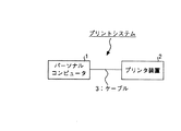
図1は,本実施の形態に係るプリントシステムの概略構成例を示す図である。図1に示すプリントシステム1は,印刷データ及び当該印刷データを印刷するための印刷条件を含む印刷ジョブを送出するパーソナルコンピュータ1と,印刷データを印刷するプリンタ装置2とが、ケーブル3を介して接続されて構築されている。
【0026】
パーソナルコンピュータ1は、作成した文書に対応した印刷データ及びこの文書印刷するために設定した印刷条件データ(用紙方向、両面、集約、製本、ステープル、パンチ、拡大/縮小等)を印刷ジョブとしてプリンタ装置2に送出する。
【0027】
プリンタ装置2は,パーソナルコンピュータ2から送出される印刷ジョブに従って印刷データの印刷を行う。具体的には,プリンタ4は,印刷ジョブに含まれる印刷条件データ(用紙方向、両面、集約、製本、ステープル、パンチ、拡大/縮小等)に従って,印刷ジョブに含まれる印刷データを紙などのメディアに印刷する。
【0028】
以下、パーソナルコンピュータ1およびプリンタ装置2の具体的な構成を順に説明する。
【0029】
[パーソナルコンピュータ]
図2は,図1で示したパーソナルコンピュータ1の概略構成を示すブロック図である。図2において,パーソナルコンピュータ1は、データを入力するための入力部11と、表示部12と、データ通信をおこなうための通信部13と、装置全体の制御を司るCPU14と、CPU14のワークエリアとして使用されるRAM15と、記録媒体17のデータのリード/ライトを行う記録媒体アクセス装置16と、CPU14を動作させるための各種プログラム等を記憶した記録媒体17とから構成されている。
【0030】
入力部11は、カーソルキー、数字入力キー及び各種機能キー等を備えたキーボード、表示部12の表示画面上でキーの選択等を行うためのマウスやスライスパット等からなり、操作者がCPU14に操作指示を与えたり、データを入力するためのユーザーインターフェースである。
【0031】
表示部12は、CRTやLCD等により構成され、CPU12から入力される表示データに応じた表示が行われる。通信部13は、外部とデータ通信するためのものであり、例えば、ケーブル3を介してプリンタ装置2等とデータ通信を行うためのものである。
【0032】
CPU14は、記録媒体17に格納されているプログラムに従って、装置全体を制御する中央制御ユニットであり、このCPU14には、入力部11、表示部12、通信部13、RAM15、記録媒体アクセス装置16が接続されており、データ通信、メモリへのアクセスによるアプリケーションプログラムの読み出しや各種データのリード/ライト、データ/コマンド入力、表示等を制御する。また,CPU14は,入力部11から入力された印刷データ及び当該印刷データの印刷条件データを印刷ジョブとして通信部13を介して,プリンタ装置2に送出する。
【0033】
RAM15は、指定されたプログラム、入力指示、入力データ及び処理結果等を格納するワークメモリと、表示部12の表示画面に表示する表示データを一時的に格納する表示メモリとを備えている。
【0034】
上記記録媒体17は、CPU14が実行可能なOSプログラム17a(例えば、WINDOWS95やWINDOWS98等)、文書作成用アプリケーションプログラム17b、プリンタ装置1に対応したプリンタドライバ17c等の各種プログラムやデータを格納する。記録媒体17としては、例えば、フロッピーディスク、ハードディスク、CD−ROM、DVD−ROM、MOやPCカード等の光学的・磁気的・電気的な記録媒体から成る。上記各種プログラムは、CPU14が読み取り可能なデータ形態で記録媒体17に格納されている。また、上記各種プログラムは、予め記録媒体に記録されている場合や通信回線を介してダウンロードされて記録媒体に格納される場合等がある。また、上記各種プログラムは通信回線を介して配信可能である。
【0035】
[プリンタ装置]
図3は,図1で示したプリンタ装置2の概略構成を示すブロック図である。図3に,プリンタ装置2は,データ通信をおこなう通信部21と,プリンタ装置2の全体の制御を司るCPU22と,CPU22を動作させる各種制御プログラムを格納したROM23と,及び各種制御プログラムのワークエリアおよびパーソナルコンピュータ1等から入力される印刷ジョブの印字データおよび印刷条件データを一時的格納するRAM24と,印字データを転写紙に印字するためのプリンタエンジン25、印字データが印字された紙をステープルするためのステープル部26、印字データが印字された転写紙に穴を空けるためのパンチ部27等から構成されており、プリンタ装置2は、両面機能、パンチ機能、ステープル機能等を備えている。
【0036】
通信部21は,外部とデータ通信を行うためのものであり、例えば、パーソナルコンピュータ2とデータ通信を行うものである。
【0037】
CPU22は,ROM23に格納されている各種制御プログラムに従って装置全体を制御する中央制御ユニットである。このCPU22には,通信部21と,ROM23と,RAM24と,プリンタエンジン25と、ステープル部26と、パンチ部27が接続されており,データ通信やプリンタ動作等を制御する。
【0038】
ROM23は,CPU21を動作させるための各種制御プログラムやその処理に使用されるパラメータ等を記憶している。RAM24は,指定された制御プログラム,処理結果,及び受信した印刷データ等を格納するワークメモリを備えている。
【0039】
プリンタエンジン25は、電子写真方式のプリンタエンジンで構成されており、印字データを転写紙に印字するユニットである。
【0040】
[パーソナルコンピュータのプリンタドライバ]
次に,上記パーソナルコンピュータ1のプリンタドライバ17cについて説明する。CPU14は、プリンタドライバ17cに従って、後述する印刷条件の設定、ワンクリックアイコンの登録、文書作成アプリケーション17bで作成した印刷データのプリンタ装置2への転送等を行う。
【0041】
プリンタドライバ17cは各印刷条件を示すイメージデータをビットマップファイル形式で備えている。プリンタドライ17cでは、印刷条件と当該印刷条件を示すイメージデータのファイルとを対応づけて記憶している。図4および図5は、印刷条件と、当該印刷条件を示すイメージデータのファイル、およびイメージデータとの対応関係を示す図である。プリンタドライバ17cには、図4および図5に示すように、▲1▼書類ベース、▲2▼集約仕切線、▲3▼集約印刷順序矢印、▲4▼スタンプ、▲5▼ステープル、パンチ、▲6▼両面等の各印刷条件毎のイメージデータが登録されている。
【0042】
プリンタドライバ17cでは、▲1▼書類ベース、▲2▼集約仕切線、▲3▼集約印刷順序矢印、▲4▼スタンプ、▲5▼ステープル、パンチ、▲6▼両面、▲7▼変倍の順にイメージデータを重ねることにより、アイコンを作成して表示画面に表示する。
【0043】
▲1▼ワンクリックアイコンの登録手順の概略
プリンタドライバでのワンクリックアイコンの登録手順の概要を図6のフローチャートを参照して説明する。図6は、プリンタドライバ17cにおけるワンクリックアイコンの登録手順の概要を説明するためのフローチャートを示している。
【0044】
図6において、表示部に表示されるプリンタドライバの印刷機能設定画面で、基準となるアイコンを選択する(ステップS1)。つぎに、ワンクリックアイコン設定画面(基準印刷条件設定画面、編集条件設定画面、仕上げ条件設定画面)で、印刷条件を選択し(ステップS2)、基準となるアイコンをベースとして、選択した印刷条件に応じた印刷結果を表すワンクリックアイコンを作成する(ステップS3)。基本条件設定画面、編集条件設定画面、仕上げ条件設定画面の1または複数の画面を選択し、印刷条件(用紙方向、両面、集約、製本、ステープル、パンチ、拡大/縮小等)の選択と当該選択した複数の印刷条件の印刷結果を示すワンクリックアイコンを作成する。
【0045】
そして、作成したワンクリックアイコンの設定名、コメントを入力し(ステップS4)、設定名、コメント、作成したワンクリックアイコン、および選択した印刷条件を対応させて記録媒体に登録する(ステップS5)。そして、この登録されたワンクリックアイコンは、以降、プリンタドライバ画面に表示され、表示されたワンクリックアイコンが選択されると、印刷条件が自動設定される。
【0046】
▲2▼プリンタドライバの表示画面
つぎに、図7〜図13を参照して、プリンタドライバの表示画面を説明する。図7はプリンタドライバの印刷機能設定画面(その1)、図8は、プリンタドライバの印刷機能設定画面(その2)、図9はワンクリックアイコンの編集条件設定画面、図10はワンクリックアイコンの基本条件設定画面、図11はワンクリックアイコンの仕上げ条件設定画面、図12はワンクリックアイコン登録画面、図13はワンクリックアイコン管理画面を示している。
【0047】
図7に示すプリンタドライバ17cの印刷機能設定画面は、文書作成アプリケーションの表示画面やOSの起動画面等で、プリンタドライバ17cの起動が選択された場合に表示される画面である。
【0048】
同図に示す印刷機能設定画面において、a1は、登録されているワンクリックアイコンが一覧表示されるアイコン表示領域を示している。アイコン表示領域a1に表示されるアイコンは、記録媒体17に格納されているイメージデータ(図4および図5参照)が重ねあわされて表示される。アイコン表示領域a1には、タテ原稿のアイコンI1、原稿タテ、集約1/2(印刷順左→右)、仕切線有りのアイコンI2,原稿タテのスタンプ(COPY)のアイコンI3、原稿タテ両面のアイコンI4,原稿タテ、集約1/2(印刷順左→右)、仕切線有り、両面のアイコンI5等が表示されている。このアイコン表示領域a1で、ワンクリックアイコンを作成する際の基準となるアイコンを選択する。
【0049】
ここで、一例としてアイコンI2を作成する場合を説明する。アイコンI2は、原稿がタテ、集約1/2(2枚の原稿を1枚に印刷)、原稿を左から右に印刷、および仕切線有りの印刷内容を示している。このアイコンI2は、▲1▼書類ベース(図4のI2MP.bmpのイメージデータ)、▲2▼集約仕切線(図4のILin2P.bmpのイメージデータ)、▲3▼集約印刷順序矢印(図4のIArr2AP.bmpのイメージデータ)の順に重ね合わせて作成する。
【0050】
a2は、原稿の方向を選択する原稿方向選択領域を示している。原稿方向選択領域a2で、原稿の「タテ」または「ヨコ」が選択する。この原稿の「タテ」または「ヨコ」の選択に応じて、アイコン表示領域a1に表示されるアイコンのタテとヨコが切り替わる。図7のアイコン表示領域a1の表示例は、原稿方向選択領域a2で「タテ」が選択されている場合を示している。原稿方向選択領域a2で「ヨコ」が選択された場合には、アイコン表示領域a1の表示例は、図8に示すように、原稿ヨコ方向のアイコンが表示される。
【0051】
また、図7において、a3は、印刷部数を選択するための印刷部数選択領域、a4は、原稿サイズを選択する原稿サイズ選択領域、a5は、印刷用紙サイズを選択するための印刷用紙サイズ選択領域を示している。
【0052】
b1は、アイコンの管理画面の表示を選択するための「アイコンの管理」キー、b2は、ワンクリックアイコンの登録を行うための画面を表示するための「ワンクリック設定の新規作成/変更」キー、b3は、印刷の実行指示を選択するための「OK」キーを示している。
【0053】
この図7の印刷機能設定画面で、アイコン表示領域a1に表示されているアイコンの中から基準となるアイコンを選択した後、「ワンクリック設定の新規作成/変更」キーb2を選択すると、ワンクリックアイコンの編集条件設定画面が表示される。
【0054】
つぎに、図9を参照してワンクリックアイコンの編集条件設定画面を説明する。同図に示す編集条件設定画面において、b11は、基本条件選択画面(図10参照)の表示を選択するための「基本」キー、b12は、編集条件選択画面(図9参照)の表示を選択するための「編集」キー、b13は、仕上げ条件選択画面(図11参照)の表示を選択するための「仕上げ」キーを示している。
【0055】
a10は、アイコン表示領域a1で選択されたアイコンの設定名が表示されるアイコン設定名表示領域、a11は、選択された印刷機能に対応したワンクリックアイコンを表示するためのワンクリックアイコン表示領域、d10は、集約/拡大連写を選択するためのラジオボタン、a12は、集約/拡大連写の種類を選択するための集約/拡大連写種類選択領域、a13は、集約/拡大連写種類選択領域a12で選択された種類に応じたアイコン(パーツ)の一覧を表示する集約/拡大連写パーツアイコン表示領域を示している。
【0056】
d1は、両面/製本を選択するためのラジオボタン、a14は、両面/製本の印刷条件のアイコン(パーツ)を表示する両面/製本パーツアイコン表示領域を示している。d4は、仕切線を選択するためのラジオボタン、d1は、スタンプを選択するためのラジオボタン、a15は、スタンプの種類を選択するためのスタンプ種類選択領域を示している。スタンプ表示種類選択領域a15では、”DRAFT”、”マルヒ”、”社外秘”等の項目が選択可能となっている。b18は、ワンクリックアイコンを登録するための登録画面の表示を選択するための「名前をつけて保存」キーを示している。
【0057】
ワンクリックアイコン表示領域a11には、集約/拡大連写種類選択領域a13で選択された印刷機能(アイコン)、両面/製本パーツアイコン表示領域a14で選択された印刷機能(アイコン)、スタンプ種類選択領域a15で選択されたスタンプに応じたワンクリックアイコンが合成されて表示される。
【0058】
つぎに、図10を参照してワンクリックアイコンの基本条件設定画面を説明する。同図に示す基本条件設定画面において、b11は、基本条件選択画面(図10参照)の表示を選択するための「基本」キー、b12は、編集条件選択画面(図9参照)の表示を選択するための「編集」キー、b13は、仕上げ条件選択画面(図11参照)の表示を選択するための「仕上げ」キーを示している。
【0059】
a10は、アイコン表示領域a1で選択されたアイコンの設定名が表示されるアイコン設定名表示領域、a11は、選択された印刷機能に対応したワンクリックアイコンを表示するためのワンクリックアイコン表示領域、b21は変倍を選択するためのラジオボタン、a21は、変倍の種類(用紙指定変倍、ズーム、独立変倍)を選択するための変倍指定領域、a22は、倍率を選択するための倍率選択領域を示している。b18は、ワンクリックアイコンを登録するための登録画面の表示を選択するための「名前をつけて保存」キーを示している。
【0060】
ワンクリックアイコン表示領域a11には、変倍指定領域a21で選択された印刷機能に応じたワンクリックアイコンが合成されて表示される。
【0061】
図11は、ワンクリックアイコンの仕上げの印刷条件を設定するための仕上げ条件設定画面の表示例を示している。同図に示す仕上げ条件設定画面において、b11は、基本条件選択画面(図10参照)の表示を選択するための「基本」キー、b12は、編集条件選択画面の表示を選択するための「編集」キー、b13は、仕上げ条件選択画面(図11参照)の表示を選択するための「仕上げ」キーを示している。
【0062】
a10は、アイコン表示領域a1で選択されたアイコンの設定名が表示されるアイコン設定名表示領域、a11は、選択された印刷機能に対応したワンクリックアイコンを表示するためのワンクリックアイコン表示領域、d31は、ステープルを選択するためのラジオボタン、a31は、各種ステープル機能を示すアイコン(パーツ)の一覧を表示するステープル(パーツ)アイコン表示領域、d32は、パンチを選択するためのラジオボタン、a4は、各種パンチ機能を示すアイコン(パーツ)を表示するパンチ(パーツ)アイコン表示領域を示している。b18は、ワンクリックアイコンを登録するための登録画面の表示を選択するための「名前をつけて保存」キーを示している。
【0063】
ワンクリックアイコン表示領域a11には、ステープル表示領域a21で選択された印刷機能およびパンチ表示領域a4で選択された印刷機能に応じたワンクリックアイコンが合成されて表示される。
【0064】
図12は、図9〜図11の画面で、「名前を付けて保存」キーが選択された場合に、表示されるワンクリック登録画面の表示例を示している。同図に示すワンクリック登録画面において、a41は、ワンクリックアイコンの設定名を入力するためのワンクリック設定名入力領域、a42は、ワンクリックアイコンに関するコメントを入力するためのワンクリック設定のコメント入力領域、b41は、ワンクリックアイコンの登録を行うための「OK」キーを示している。
【0065】
ワンクリック設定名入力領域a41で、ワンクリック設定名を入力し、また、ワンクリック設定のコメント入力領域でワンクリックアイコンに関するコメントを入力した後、「OK」キーb41を選択すると、設定名、コメント、作成したワンクリックアイコン、および選択した印刷条件が対応づけられて記録媒体17に登録される。
【0066】
図13は、図7の印刷機能選択画面で、「アイコンの管理」キーb1が選択された場合に表示されるアイコン管理画面の一例を示している。印刷機能選択画面で、a41は、登録されているワンクリックアイコンが一覧表示されるアイコン表示領域、b51は、アイコン表示領域a41で選択されているアイコンを前に移動するための「前に移動」キー、b53は、アイコン表示領域a41で選択されているアイコンを後ろ移動するための「後ろに移動」キー、アイコン表示領域a41で選択されているアイコンを削除するための「ワンクリック設定削除」キーを示している。
【0067】
アイコン表示領域a41でアイコンを選択し、「前に移動」キーb42を1回押下すると、選択されているアイコンが左側に表示されているアイコンと表示順が入れ替わり、1つ前に移動する。また、アイコン表示領域a41でアイコンを選択し、「後ろに移動」キーb42を1回押下すると、選択されているアイコンが右側に表示されているアイコンと表示順が入れ替わり、1つ後ろに移動する。また、アイコン表示領域a41でアイコンを選択し、「ワンクリック設定削除」キーb42を選択すると、選択したアイコンのワンクリック設定を削除する。
【0068】
▲3▼ワンクリックアイコンの登録手順の具体例
つぎに、ワンクリックアイコンの登録手順の具体例を図14〜図21を参照して説明する。図14〜図21は、ワンクリックアイコンの登録手順の具体例を説明するためにプリンタードライバ画面の表示例を示す図である。一例として、集約1/2(仕切線有り)および左上ステープルの機能を表すワンクリックアイコンを作成する具体的な手順を図14〜図17を参照して説明する。
【0069】
まず、上記図7に示す印刷機能設定画面のアイコン表示領域a1に表示されているアイコンの中から基準となるアイコンとして、”アイコンI1(設定名:通常)”を選択し、原稿方向選択領域a2で”タテ”方向を選択した後、「ワンクリック設定の新規作成/変更」キーb2を選択すると、図9に示す編集条件設定画面が表示される。
【0070】
図9に示す編集条件設定画面では、ワンクリックアイコン設定名表示領域a2には、図7に示す印刷機能設定画面のアイコン表示領域a1で選択された設定名”通常”が表示される。また、ワンクリックアイコン表示領域a11では、図7のアイコン表示領域a1で選択された”アイコンI1(設定名:通常)”が表示される。
【0071】
そして、図14に示すように、集約/拡大連写を選択するためのラジオボタンd1を選択し、集約/拡大連写種類選択領域a12で、”2ページを1ページに集約”を選択すると、集約/拡大連写パーツアイコン表示領域a13には、2ページを1ページに集約する印刷結果を示すアイコンI11、I12が表示される。アイコンI11は、左から右に2ページを1ページに集約する印刷結果を示しており、アイコンI12は、右から左に2ページを1ページに集約する印刷結果を示している。そして、集約/拡大連写パーツアイコン表示領域a13で、アイコンI11を選択すると、ワンクリックアイコン表示領域a3には、左から右に2ページを1ページに集約する印刷結果を示すアイコンI100が表示される。これは、書類ベースのイメージデータに、矢印のイメージデータを重ね書きしたものである。
【0072】
つづいて、図15に示すように、仕切線を選択するためのラジオボタンd13を選択すると、ワンクリックアイコン表示領域a3には、アイコンI100(図14参照)に、仕切線が描画されたアイコンI101が表示される。これは、アイコンI101(図14参照)に仕切線のイメージデータを重ね書きしたものである。
【0073】
つづいて、図15の画面で「編集キー」b12を選択して、編集条件設定画面を表示する。そして、編集条件設定画面で、図16に示すように、ステープルを選択するためのラジオボタンd31を選択すると、ステープル(パーツ)アイコン表示領域a31には、左上ステープルの印刷結果を示すアイコンI21,右上ステープルの印刷結果を示すアイコンI22、左斜めステープルのアイコンI23、左側2カ所ステープルのアイコンI24、および右側2カ所ステープルのアイコンI25の5つのアイコンが表示される。
【0074】
このステープル(パーツ)アイコン表示領域a31で、左上ステープルのアイコンI21を選択すると、ワンクリックアイコン表示領域a31には、図15のアイコンI101に、左上ステープルのイメージが描画されたアイコンI102が表示される。アイコンI102は、アイコンI101(図15参照)に左上ステープルのイメージを重ね書きしたものである。これにより、集約1/2(左から右に印刷)、仕切線有り、および左上ステープルの印刷結果を示すワンクリックアイコンが作成されたことになる。
【0075】
そして、図16で、「名前をつけて保存」キーb18を選択すると、図12に示すワンクリックアイコン登録画面が表示され、ワンクリック設定名入力領域a41で、設定名として、”集約1/2ステープル左上”を入力し、また、ワンクリック設定のコメント入力領域でワンクリックアイコンに関するコメントを入力した後、「OK」キーb41を選択すると、設定名”集約1/2ステープル左上”、コメント、作成したワンクリックアイコンI102、および選択した印刷機能(集約1/2(左から右に印刷)、仕切線有り、および左上ステープル)が対応づけられてプリンタドライバ17c(記録媒体17)に登録される。
【0076】
この登録されたワンクリックアイコンは、図17に示すように、印刷機能設定画面のワンクリックアイコン表示領域a1に表示される。この設定名”集約1/2ステープル左上”のアイコンI102を選択すると、集約1/2(左から右に印刷)、仕切線有り、および左上ステープルの印刷条件が自動的に設定される。
【0077】
つぎに、「両面」、「スタンプ」、および「パンチ」の機能を表すワンクリックアイコンを作成する具体的な手順を図18〜図21を参照して説明する。具体的な説明する。
【0078】
まず、上記図7に示す印刷機能設定画面のアイコン表示領域a1に表示されているアイコンの中から基準となるアイコンとして、”アイコンI1(設定名:通常)”を選択し、原稿方向選択領域a2で”タテ”方向を選択した後、「ワンクリック設定の新規作成/変更」キーb2を選択すると、図9に示す編集条件設定画面が表示される。
【0079】
図9に示す編集条件設定画面では、ワンクリックアイコン設定名表示領域a2には、図7に示す印刷機能設定画面のアイコン表示領域a1で選択された設定名”通常”が表示される。また、ワンクリックアイコン表示領域a11では、図7のアイコン表示領域a1で選択された”アイコンI1(設定名:通常)”が表示される。
【0080】
そして、図18に示すように、両面/製本を選択するためのラジオボタンd2を選択すると、両面/製本パーツアイコン表示領域a14には、両面または製本の印刷結果を示すアイコンI13〜I15等が表示される。両面/製本パーツアイコン表示領域a14で、両面の印刷結果を示すアイコンI21を選択すると、、ワンクリックアイコン表示領域a1には、両面の印刷結果を示すアイコンI200が表示される。このアイコンI200は、書類ベースのイメージに両面のイメージを重ね書きしたものである。
【0081】
つづいて、図19に示すように、スタンプを選択するためのラジオボタンd3を選択すると、スタンプの種類を選択するためのスタンプ種類選択領域a15にスタンプが表示される。このスタンプ種類選択領域a15でカーソルキーを操作して、”マルヒ”を選択すると、ワンクリックアイコン設定名表示領域a2には、アイコンI200(図18参照)に、マルヒの文字が描画されたアイコンI201が表示される。このアイコンI201は、アイコンI200(図18参照)に、マルヒの文字のイメージを重ね書きしたものである。
【0082】
つぎに、図19の画面の仕上げキーb13を選択して、図仕上げ条件設定画面を表示し、図20に示すように、パンチを選択するためのラジオボタンd32を選択すると、パンチ(パーツ)アイコン表示領域a32には、左側パンチの印刷結果を示すアイコンI25、右側パンチのアイコン結果を示すアイコンI26が表示される。そして、左側パンチの印刷結果を示すアイコンI25を選択すると、ワンクリックアイコン表示領域a1には、アイコンI201(図19参照)に、左側パンチのイメージが描画されたアイコンI202が表示される。このアイコンI202は、アイコンI201(図19参照)に、左側パンチのイメージを重ね書きしたものである。
【0083】
そして、図20で、「名前をつけて保存」キーb18を選択すると、図12に示すワンクリックアイコン登録画面が表示される。そして、このワンクリック設定名入力領域a41にワンクリック名として、”両面スタンプパンチ”を入力し、また、ワンクリック設定のコメント入力領域a42で、作成したワンクリックアイコンに関するコメントを入力した後、「OK」キーb42を選択すると、設定名”両面スタンプパンチ”、コメント、作成したワンクリックアイコンI202、および選択した印刷機能(両面、スタンプ、左パンチ)が対応づけられてプリンタドライバに登録される。
【0084】
この登録されたワンクリックアイコンは、図21に示すように、印刷機能設定画面のワンクリックアイコン表示領域a1に表示される。この設定名””両面スタンプパンチ”のアイコンI102を選択すると、対応する印刷機能(両面、スタンプ、左パンチ)が自動的に設定される。
【0085】
▲4▼ワンクリックアイコンを使用した印刷動作
次に,プリンタドライバ17cのワンクリックアイコンを使用して、文書データを印刷する場合の手順を図22のフローチャートを参照して説明する。図22は、プリンタドライバ17cのワンクリックアイコンを使用して、文書データを印刷する場合の手順を説明するためのフローチャートである。
【0086】
図22において、まず、文書作成アプリケーションで文書を作成し(ステップS10)、文書作成アプリケーション17bの表示画面でプリンタドライバ17cを起動させて、プリンタドライバーの印刷機能設定画面(図7参照)を表示する(ステップS11)。つづいて、印刷機能設定画面のアイコン表示領域a1に表示されるワンクリックアイコンの中から所望のワンクリックアイコンを選択すると(ステップS12)、選択されたワンクリックアイコンに対応させて登録している印刷条件が自動設定される。そして、他の印刷条件(給紙トレイ、用紙種類、排紙先、部数等)を設定した後(ステップS13)、OKボタンb3が選択されると、ワンクリックアイコンに対応させて登録されている印刷条件および他の印刷条件等の印刷条件データおよび文書データがパーソナルコンピュータ2からプリンタ装置2に転送される(ステップS14)。これに応じて、プリンタ装置では、転送されてくる印刷条件データに従って、文書データを印字する。
【0087】
以上説明したように本実施の形態のプリンタドライバ17cでは、各々が1または複数の印刷機能を表すワンクリックアイコンの一覧をアイコン表示領域a1に表示し、アイコン表示領域a1に表示されたワンクリックアイコンの一覧の中から1のワンクリックアイコンを選択し、選択したワンクリックアイコンに対応した複数の印刷機能を自動設定することとしたので、印刷データをプリンタ装置で印刷する際に、簡単にプリンタ装置の印刷機能の設定を行うことが可能となる。
【0088】
また、本実施の形態のプリンタドライバ17cでは、表示画面上に、複数の印刷機能をワンクリックアイコン設定画面(編集条件設定画面、仕上げ条件設定画面、基本条件設定画面等)で選択して、選択された複数の印刷機能を表すワンクリックアイコンを作成して、ワンクリックアイコン表示領域a11に表示し、選択された複数の印刷機能と、複数の印刷機能を表すワンクリックアイコンと、設定名を対応づけて登録することとしたので、ユーザが所望の複数の印刷機能を表すワンクリックアイコンを作成し、作成したワンクリックアイコンを選択することで複数の印刷機能を自動設定でき、ユーザーの使い勝手が良くなる。
【0089】
なお、本発明は、上記した実施の形態に限定されるものではなく、発明の要旨を変更しない範囲で適宜変形可能である。
【0090】
【発明の効果】
以上説明したように、本発明によれば、画像データを印刷する際に、簡単に印刷条件の設定を行うことができる。
【図面の簡単な説明】
【図1】本実施の形態にかかるプリンタシステムの概略構成を示す図である。
【図2】図1のパーソナルコンピュータの構成を示すブロック図である。
【図3】図1のプリンタ装置の構成を示すブロック図である。
【図4】印刷条件と、当該印刷条件を示すイメージデータのファイル、およびイメージデータとの対応関係を説明するための図(その1)である。
【図5】印刷条件と、当該印刷条件を示すイメージデータのファイル、およびイメージデータとの対応関係を説明するための図(その2)である。
【図6】プリンタドライバのワンクリックアイコンの登録手順の概要を説明するためのフローチャートである。
【図7】プリンタドライバの印刷機能設定画面(その1)を示す図である。
【図8】プリンタドライバの印刷機能設定画面(その2)を示す図である。
【図9】ワンクリックアイコンの編集条件設定画面を示す図である。
【図10】ワンクリックアイコンの基本条件設定画面を示す図である。
【図11】ワンクリックアイコンの仕上げ条件設定画面を示す図である。
【図12】ワンクリックアイコン登録画面を示す図である。
【図13】ワンクリックアイコン管理画面を示す図である。
【図14】ワンクリックアイコンの登録手順を具体的に説明するための表示画面の表示例を示す図である。
【図15】ワンクリックアイコンの登録手順を具体的に説明するための表示画面の表示例を示す図である。
【図16】ワンクリックアイコンの登録手順を具体的に説明するための表示画面の表示例を示す図である。
【図17】ワンクリックアイコンの登録手順を具体的に説明するための表示画面の表示例を示す図である。
【図18】ワンクリックアイコンの登録手順を具体的に説明するための表示画面の表示例を示す図である。
【図19】ワンクリックアイコンの登録手順を具体的に説明するための表示画面の表示例を示す図である。
【図20】ワンクリックアイコンの登録手順を具体的に説明するための表示画面の表示例を示す図である。
【図21】ワンクリックアイコンの登録手順を具体的に説明するための表示画面の表示例を示す図である。
【図22】プリンタドライバのワンクリックアイコンを使用して、文書データを印刷する場合の手順を説明するためのフローチャートである。
【符号の説明】
1 パーソナルコンピュータ
2 プリンタ装置
3 ケーブル
11 入力部
12 表示部
13 通信部
14 CPU
15 RAM
16 記録媒体アクセス装置
17 記録媒体
17a OSプログラム
17b 文書作成アプリケーションプログラム
17c プリンタドライバ
21 通信部
22 CPU
23 ROM
24 RAM
25 プリンタエンジン
26 ステープル部
27 パンチ部
a1 アイコン表示領域
a2 原稿方向選択領域
a3 印刷部数選択領域
a4 原稿サイズ選択領域
a5 印刷用紙サイズ選択領域
a11 ワンクリックアイコン表示領域
a12 集約/拡大連写種類選択領域
a13 集約/拡大連写パーツアイコン表示領域
a14 両面/製本パーツアイコン表示領域
a15 スタンプ種類選択領域
a21 変倍指定領域
a22 倍率選択領域
a31 ステープル(パーツ)アイコン表示領域、
a32 パンチ(パーツ)アイコン表示領域
b1 「アイコンの管理」キー、
b2 「ワンクリック設定の新規作成/変更」キー
b3 「OK」キー
b11 「基本」キー
b12 「編集」キー
b13 「仕上げ」キー
b18 「名前をつけて保存」キー
b51 「前に移動」キー
b52 「後ろに移動」キー
b53 「ワンクリック設定削除」キー
d1 集約/拡大連写を選択するためのラジオボタン
d2 両面/製本を選択するためのラジオボタン
d3 スタンプを選択するためのラジオボタン
d4 仕切線を選択するためのラジオボタン
d10 集約/拡大連写を選択するためのラジオボタン
d11 両面/製本を選択するためのラジオボタン
d13 仕切線を選択するためのラジオボタン
d31 ステープルを選択するためのラジオボタン
d32 パンチを選択するためのラジオボタン[0001]
BACKGROUND OF THE INVENTION
The present invention relates to a printing condition setting device that receives setting of a printing condition via a display unit when printing image data, Printing device, printing system, The present invention also relates to a printing condition setting recording medium.
[0002]
[Prior art]
Recently, printer devices have become increasingly functional and sophisticated, and printer settings have become complicated and difficult for users. Specifically, it is difficult for the user to set printing conditions on the printer driver screen. Such a printer driver is a software program designed to allow a specific program to be operated by another program without bothering the printer hardware and the internal “language”, and for controlling the printer. In this case, the output data is processed. Different printers require different codes and commands to operate the printer correctly and use their special functions and capabilities. Application programs can interact accurately with a variety of printers using printer drivers that handle all the slightly different functions of each printer instead of application programs. In Windows 95/98, MacOS, and the like, the printer driver is managed by the OS.
[0003]
[Problems to be solved by the invention]
The present invention has been made in view of the above, and can easily set printing conditions when printing image data. Provided printing condition setting device, printing device, printing system, and recording medium for printing condition setting The purpose is to do.
[0004]
[Means for Solving the Problems]
In order to solve the above-mentioned problems, the invention according to
[0009]
[0010]
[0011]
[0012]
Claims 5 The present invention relates to a printing system,
[0014]
Claims 6 The invention according to the present invention is a printing condition setting recording medium readable by a computer,
[0024]
DETAILED DESCRIPTION OF THE INVENTION
Hereinafter, with reference to the drawings, preferred embodiments of an information processing apparatus and a printing condition setting method according to the present invention will be described as [print system according to the present embodiment], [personal computer], [printer apparatus], [ Details will be described in the order of “printer driver of personal computer”. In this specification, “printing condition” and “printing function” are used as synonymous terms. The “symbol” is used as a broad concept term including an image such as an icon.
[0025]
[Print System According to this Embodiment]
FIG. 1 is a diagram illustrating a schematic configuration example of a print system according to the present embodiment. A
[0026]
The
[0027]
The
[0028]
Hereinafter, specific configurations of the
[0029]
[Personal computer]
FIG. 2 is a block diagram showing a schematic configuration of the
[0030]
The
[0031]
The
[0032]
The
[0033]
The
[0034]
The recording medium 17 stores various programs and data such as an
[0035]
[Printer]
FIG. 3 is a block diagram showing a schematic configuration of the
[0036]
The
[0037]
The
[0038]
The
[0039]
The
[0040]
[Printer driver for personal computer]
Next, the
[0041]
The
[0042]
In the
[0043]
(1) Outline of one-click icon registration procedure
An outline of the registration procedure of the one-click icon in the printer driver will be described with reference to the flowchart of FIG. FIG. 6 is a flowchart for explaining an outline of the one-click icon registration procedure in the
[0044]
In FIG. 6, a reference icon is selected on the print function setting screen of the printer driver displayed on the display unit (step S1). Next, on the one-click icon setting screen (standard printing condition setting screen, editing condition setting screen, finishing condition setting screen), the printing condition is selected (step S2), and the selected printing condition is set based on the reference icon. A one-click icon representing the corresponding print result is created (step S3). Select one or more of the basic condition setting screen, editing condition setting screen, and finishing condition setting screen, and select and select the printing conditions (paper orientation, duplex, consolidation, bookbinding, staple, punch, enlargement / reduction, etc.) A one-click icon indicating the printing result of the plurality of printing conditions is created.
[0045]
Then, the setting name and comment of the created one-click icon are input (step S4), and the setting name, the comment, the created one-click icon, and the selected printing condition are associated with each other and registered in the recording medium (step S5). The registered one-click icon is then displayed on the printer driver screen, and when the displayed one-click icon is selected, the printing conditions are automatically set.
[0046]
(2) Printer driver display screen
Next, a display screen of the printer driver will be described with reference to FIGS. 7 is a print function setting screen (No. 1) of the printer driver, FIG. 8 is a print function setting screen (No. 2) of the printer driver, FIG. 9 is an edit condition setting screen of a one-click icon, and FIG. FIG. 11 shows a one-click icon finishing condition setting screen, FIG. 12 shows a one-click icon registration screen, and FIG. 13 shows a one-click icon management screen.
[0047]
The print function setting screen of the
[0048]
In the print function setting screen shown in the figure, a1 indicates an icon display area where a list of registered one-click icons is displayed. The icon displayed in the icon display area a1 is displayed by superimposing image data (see FIGS. 4 and 5) stored in the recording medium 17. In the icon display area a1, there are a vertical document icon I1, a document length,
[0049]
Here, a case where the icon I2 is created will be described as an example. The icon I2 indicates the content of the document that is vertical, consolidated 1/2 (prints two documents on one sheet), prints the document from left to right, and prints with divider lines. This icon I2 includes (1) document base (image data of I2MP.bmp in FIG. 4), (2) aggregation partition line (image data of ILin2P.bmp in FIG. 4), (3) aggregation print order arrow (FIG. 4). IArr2AP.bmp image data) in this order.
[0050]
Reference numeral a2 denotes a document direction selection area for selecting a document direction. In the document orientation selection area a2, “Vertical” or “Horizontal” of the document is selected. In accordance with the selection of “vertical” or “horizontal” of the document, the vertical and horizontal icons are switched in the icon display area a1. The display example of the icon display area a1 in FIG. 7 shows a case where “vertical” is selected in the document direction selection area a2. When “horizontal” is selected in the original direction selection area a2, the icon display area a1 displays an icon in the original horizontal direction as shown in FIG.
[0051]
In FIG. 7, a3 is a print number selection area for selecting the number of copies, a4 is a document size selection area for selecting a document size, and a5 is a print sheet size selection area for selecting a print sheet size. Is shown.
[0052]
b1 is an “icon management” key for selecting an icon management screen display, and b2 is a “one-click setting new creation / change” key for displaying a screen for registering a one-click icon. , B3 indicate an “OK” key for selecting a print execution instruction.
[0053]
When a reference icon is selected from the icons displayed in the icon display area a1 on the print function setting screen in FIG. 7 and then the "new / change one-click setting" key b2 is selected, one-click The icon editing condition setting screen is displayed.
[0054]
Next, the one-click icon editing condition setting screen will be described with reference to FIG. In the editing condition setting screen shown in the figure, b11 is a “basic” key for selecting the display of the basic condition selection screen (see FIG. 10), and b12 is the display of the editing condition selection screen (see FIG. 9). An “edit” key b13 for indicating the “finishing” key for selecting display of a finishing condition selection screen (see FIG. 11).
[0055]
a10 is an icon setting name display area in which the setting name of the icon selected in the icon display area a1 is displayed; a11 is a one-click icon display area for displaying a one-click icon corresponding to the selected print function; d10 is a radio button for selecting aggregation / enlarged continuous shooting, a12 is an aggregation / enlarged continuous shooting type selection area for selecting the type of aggregation / enlarged continuous shooting, and a13 is an aggregation / enlarged continuous shooting type selection. An aggregation / enlarged continuous shooting part icon display area for displaying a list of icons (parts) corresponding to the type selected in the area a12 is shown.
[0056]
d1 indicates a radio button for selecting double-sided / bookbinding, and a14 indicates a double-sided / bookbinding part icon display area for displaying double-sided / bookbinding printing condition icons (parts). d4 is a radio button for selecting a partition line, d1 is a radio button for selecting a stamp, and a15 is a stamp type selection area for selecting the type of stamp. In the stamp display type selection area a15, items such as “DRAFT”, “Maruchi”, “confidential” can be selected. b18 shows a "save as" key for selecting display of a registration screen for registering a one-click icon.
[0057]
The one-click icon display area a11 includes a printing function (icon) selected in the consolidation / enlarged continuous shooting type selection area a13, a printing function (icon) selected in the duplex / binding part icon display area a14, and a stamp type selection area. A one-click icon corresponding to the stamp selected in a15 is synthesized and displayed.
[0058]
Next, a basic condition setting screen for a one-click icon will be described with reference to FIG. In the basic condition setting screen shown in the figure, b11 is a “basic” key for selecting display of the basic condition selection screen (see FIG. 10), and b12 is selection of display of the editing condition selection screen (see FIG. 9). An “edit” key b13 for indicating the “finishing” key for selecting display of a finishing condition selection screen (see FIG. 11).
[0059]
a10 is an icon setting name display area in which the setting name of the icon selected in the icon display area a1 is displayed; a11 is a one-click icon display area for displaying a one-click icon corresponding to the selected print function; b21 is a radio button for selecting magnification, a21 is a magnification designation area for selecting the type of magnification (paper designated magnification, zoom, independent magnification), and a22 is a magnification for selecting a magnification. A magnification selection area is shown. b18 shows a "save as" key for selecting display of a registration screen for registering a one-click icon.
[0060]
In the one-click icon display area a11, a one-click icon corresponding to the print function selected in the scaling specification area a21 is synthesized and displayed.
[0061]
FIG. 11 shows a display example of a finishing condition setting screen for setting finishing printing conditions for the one-click icon. In the finishing condition setting screen shown in the figure, b11 is a “basic” key for selecting display of the basic condition selection screen (see FIG. 10), and b12 is “edit” for selecting display of the editing condition selection screen. The “” key and
[0062]
a10 is an icon setting name display area in which the setting name of the icon selected in the icon display area a1 is displayed; a11 is a one-click icon display area for displaying a one-click icon corresponding to the selected print function; d31 is a radio button for selecting staples, a31 is a staple (parts) icon display area for displaying a list of icons (parts) indicating various staple functions, d32 is a radio button for selecting punches, a4 Shows a punch (parts) icon display area for displaying icons (parts) indicating various punch functions. b18 shows a "save as" key for selecting display of a registration screen for registering a one-click icon.
[0063]
In the one-click icon display area a11, a one-click icon corresponding to the print function selected in the staple display area a21 and the print function selected in the punch display area a4 is synthesized and displayed.
[0064]
FIG. 12 shows a display example of the one-click registration screen that is displayed when the “Save As” key is selected on the screens of FIGS. 9 to 11. In the one-click registration screen shown in the figure, a41 is a one-click setting name input area for inputting a setting name of a one-click icon, and a42 is a one-click setting comment input for inputting a comment regarding the one-click icon. An area b41 indicates an “OK” key for registering a one-click icon.
[0065]
When a one-click setting name is input in the one-click setting name input area a41, and a comment related to the one-click icon is input in the one-click setting comment input area, the "OK" key b41 is selected. The created one-click icon and the selected printing condition are associated with each other and registered in the recording medium 17.
[0066]
FIG. 13 shows an example of an icon management screen that is displayed when the “icon management” key b1 is selected on the print function selection screen of FIG. In the print function selection screen, a41 is an icon display area where a list of registered one-click icons is displayed, and b51 is "move forward" for moving the icon selected in the icon display area a41 forward. The key b53 is a “move backward” key for moving the icon selected in the icon display area a41 backward, and a “one-click setting delete” key for deleting the icon selected in the icon display area a41. Is shown.
[0067]
When an icon is selected in the icon display area a41 and the “move forward” key b42 is pressed once, the display order of the selected icon is switched with the icon displayed on the left side, and the icon is moved to the previous one. Further, when an icon is selected in the icon display area a41 and the “move backward” key b42 is pressed once, the display order of the selected icon is switched with the icon displayed on the right side, and the icon is moved backward by one. . When an icon is selected in the icon display area a41 and the “delete one-click setting” key b42 is selected, the one-click setting of the selected icon is deleted.
[0068]
(3) Specific example of one-click icon registration procedure
Next, a specific example of the one-click icon registration procedure will be described with reference to FIGS. FIGS. 14 to 21 are diagrams showing display examples of the printer driver screen for explaining a specific example of the one-click icon registration procedure. As an example, a specific procedure for creating a one-click icon representing the functions of
[0069]
First, “icon I1 (setting name: normal)” is selected as a reference icon from the icons displayed in the icon display area a1 of the print function setting screen shown in FIG. 7, and the document orientation selection area a2 is selected. After selecting the “Vertical” direction with the button, when the “Create / change one-click setting newly” key b2 is selected, an editing condition setting screen shown in FIG. 9 is displayed.
[0070]
In the editing condition setting screen shown in FIG. 9, the setting name “normal” selected in the icon display area a1 of the print function setting screen shown in FIG. 7 is displayed in the one-click icon setting name display area a2. In the one-click icon display area a11, the “icon I1 (setting name: normal)” selected in the icon display area a1 in FIG. 7 is displayed.
[0071]
Then, as shown in FIG. 14, when the radio button d1 for selecting aggregation / enlarged continuous shooting is selected, and “aggregate 2 pages into 1 page” is selected in the aggregation / enlarged continuous shooting type selection area a12, In the aggregation / enlarged continuous shooting parts icon display area a13, icons I11 and I12 are displayed that indicate the print results of integrating two pages into one page. The icon I11 indicates a print result of combining two pages into one page from the left to the right, and the icon I12 indicates a print result of combining two pages into one page from the right to the left. When the icon I11 is selected in the aggregation / enlarged continuous shooting part icon display area a13, an icon I100 indicating a print result of integrating two pages into one page from the left to the right is displayed in the one-click icon display area a3. The This is a document-based image data overlaid with arrow image data.
[0072]
Subsequently, as shown in FIG. 15, when the radio button d13 for selecting a partition line is selected, an icon I101 in which a partition line is drawn on the icon I100 (see FIG. 14) is displayed in the one-click icon display area a3. Is displayed. This is the icon I101 (see FIG. 14) overwritten with the image data of the partition lines.
[0073]
Subsequently, the “edit key” b12 is selected on the screen of FIG. 15, and the edit condition setting screen is displayed. When the radio button d31 for selecting staples is selected on the editing condition setting screen as shown in FIG. 16, an icon I21 indicating the print result of the upper left staple is displayed in the staple (parts) icon display area a31, and the upper right corner. Five icons are displayed: an icon I22 indicating a staple printing result, an oblique left staple icon I23, two left staple icons I24, and two right staple icons I25.
[0074]
When the upper left staple icon I21 is selected in the staple (parts) icon display area a31, an icon I102 in which an image of the upper left staple is drawn is displayed on the icon I101 of FIG. 15 in the one-click icon display area a31. . The icon I102 is obtained by overwriting the upper left staple image on the icon I101 (see FIG. 15). As a result, a one-click icon indicating a print result of
[0075]
When the “Save As” key b18 in FIG. 16 is selected, the one-click icon registration screen shown in FIG. 12 is displayed. In the one-click setting name input area a41, the setting name is “
[0076]
As shown in FIG. 17, the registered one-click icon is displayed in the one-click icon display area a1 of the print function setting screen. When the icon I102 of the setting name “
[0077]
Next, a specific procedure for creating one-click icons representing the functions of “both sides”, “stamp”, and “punch” will be described with reference to FIGS. A specific explanation will be given.
[0078]
First, “icon I1 (setting name: normal)” is selected as a reference icon from the icons displayed in the icon display area a1 of the print function setting screen shown in FIG. 7, and the document orientation selection area a2 is selected. After selecting the “Vertical” direction with the button, when the “Create / change one-click setting newly” key b2 is selected, an editing condition setting screen shown in FIG. 9 is displayed.
[0079]
In the editing condition setting screen shown in FIG. 9, the setting name “normal” selected in the icon display area a1 of the print function setting screen shown in FIG. 7 is displayed in the one-click icon setting name display area a2. In the one-click icon display area a11, the “icon I1 (setting name: normal)” selected in the icon display area a1 in FIG. 7 is displayed.
[0080]
Then, as shown in FIG. 18, when the radio button d2 for selecting double-sided / bookbinding is selected, icons I13 to I15 indicating double-sided or bookbinding printing results are displayed in the double-sided / bookbinding part icon display area a14. Is done. When the icon I21 indicating the double-sided printing result is selected in the double-sided / bookbinding part icon display area a14, the icon I200 indicating the double-sided printing result is displayed in the one-click icon display area a1. This icon I200 is obtained by overwriting a double-sided image on a document-based image.
[0081]
Subsequently, as shown in FIG. 19, when a radio button d3 for selecting a stamp is selected, the stamp is displayed in a stamp type selection area a15 for selecting a stamp type. When the cursor key is operated in the stamp type selection area a15 to select "March", the icon I201 in which the letters of March are drawn on the icon I200 (see FIG. 18) is displayed in the one-click icon setting name display area a2. Is displayed. This icon I201 is an icon I200 (see FIG. 18) overwritten with an image of Maruhi characters.
[0082]
Next, the finishing key b13 on the screen of FIG. 19 is selected to display the drawing finishing condition setting screen. As shown in FIG. 20, when the radio button d32 for selecting a punch is selected, a punch (parts) icon is displayed. In the display area a32, an icon I25 indicating the printing result of the left punch and an icon I26 indicating the icon result of the right punch are displayed. When the icon I25 indicating the printing result of the left punch is selected, the icon I202 in which the image of the left punch is drawn is displayed on the icon I201 (see FIG. 19) in the one-click icon display area a1. This icon I202 is obtained by overwriting the left punch image on the icon I201 (see FIG. 19).
[0083]
Then, when the “Save As” key b18 is selected in FIG. 20, a one-click icon registration screen shown in FIG. 12 is displayed. Then, “double-sided stamp punch” is input as a one-click name in the one-click setting name input area a41, and a comment regarding the created one-click icon is input in the one-click setting comment input area a42. When the “OK” key b42 is selected, the setting name “double-sided stamp punch”, the comment, the created one-click icon I202, and the selected printing function (double-sided, stamp, left punch) are associated and registered in the printer driver.
[0084]
As shown in FIG. 21, the registered one-click icon is displayed in the one-click icon display area a1 of the print function setting screen. When this setting name “double-sided stamp punch” icon I102 is selected, the corresponding printing function (double-sided, stamp, left punch) is automatically set.
[0085]
(4) Printing operation using one-click icon
Next, a procedure for printing document data using the one-click icon of the
[0086]
In FIG. 22, first, a document is created by the document creation application (step S10), the
[0087]
As described above, in the
[0088]
In the
[0089]
The present invention is not limited to the above-described embodiment, and can be appropriately modified without changing the gist of the invention.
[0090]
【The invention's effect】
As explained above, according to the present invention, Easily set printing conditions when printing image data .
[Brief description of the drawings]
FIG. 1 is a diagram illustrating a schematic configuration of a printer system according to an embodiment.
FIG. 2 is a block diagram illustrating a configuration of the personal computer of FIG. 1;
FIG. 3 is a block diagram illustrating a configuration of the printer apparatus of FIG. 1;
FIG. 4 is a diagram (No. 1) for explaining a correspondence relationship between a printing condition, an image data file indicating the printing condition, and image data;
FIG. 5 is a diagram (No. 2) for explaining a correspondence relationship between a printing condition, an image data file indicating the printing condition, and the image data;
FIG. 6 is a flowchart for explaining an outline of a one-click icon registration procedure of a printer driver.
FIG. 7 is a diagram illustrating a print function setting screen (part 1) of the printer driver.
FIG. 8 is a diagram illustrating a print function setting screen (part 2) of the printer driver.
FIG. 9 is a view showing an editing condition setting screen for a one-click icon.
FIG. 10 is a diagram showing a basic condition setting screen for a one-click icon.
FIG. 11 is a diagram showing a finishing condition setting screen for a one-click icon.
FIG. 12 is a diagram showing a one-click icon registration screen.
FIG. 13 is a diagram showing a one-click icon management screen.
FIG. 14 is a diagram showing a display example of a display screen for specifically explaining a one-click icon registration procedure.
FIG. 15 is a diagram showing a display example of a display screen for specifically explaining a one-click icon registration procedure;
FIG. 16 is a diagram illustrating a display example of a display screen for specifically explaining a one-click icon registration procedure;
FIG. 17 is a diagram illustrating a display example of a display screen for specifically explaining a one-click icon registration procedure;
FIG. 18 is a diagram showing a display example of a display screen for specifically explaining a procedure for registering a one-click icon.
FIG. 19 is a diagram showing a display example of a display screen for specifically explaining a one-click icon registration procedure;
FIG. 20 is a diagram showing a display example of a display screen for specifically explaining a one-click icon registration procedure.
FIG. 21 is a diagram showing a display example of a display screen for specifically explaining a one-click icon registration procedure.
FIG. 22 is a flowchart illustrating a procedure for printing document data using a one-click icon of a printer driver.
[Explanation of symbols]
1 Personal computer
2 Printer device
3 Cable
11 Input section
12 Display section
13 Communication Department
14 CPU
15 RAM
16 Recording medium access device
17 Recording media
17a OS program
17b Document creation application program
17c Printer driver
21 Communication Department
22 CPU
23 ROM
24 RAM
25 Printer Engine
26 Staple section
27 Punch
a1 Icon display area
a2 Document orientation selection area
a3 Number of copies selection area
a4 Document size selection area
a5 Printing paper size selection area
a11 One-click icon display area
a12 Aggregation / enlarged continuous shooting type selection area
a13 Aggregation / enlarged continuous shooting part icon display area
a14 Double-sided / bookbinding part icon display area
a15 Stamp type selection area
a21 Magnification designation area
a22 Magnification selection area
a31 Staple (parts) icon display area,
a32 Punch (parts) icon display area
b1 “Manage icons” key,
b2 “Create / Change One-Click Settings” key
b3 “OK” key
b11 "Basic" key
b12 “Edit” key
b13 “Finish” key
b18 “Save As” key
b51 “Move forward” key
b52 “Move backward” key
b53 “Delete one-click setting” key
d1 Radio button for selecting consolidation / enlarged continuous shooting
d2 Radio button for selecting duplex / binding
d3 Radio button for selecting a stamp
d4 Radio button for selecting divider
d10 Radio button for selecting consolidated / expanded continuous shooting
d11 Radio button for selecting duplex / binding
d13 Radio button for selecting divider line
d31 Radio button for selecting staples
d32 Radio button for selecting punch
Claims (6)
複数の印刷条件に応じた印刷結果を示すイメージを表示するイメージ表示領域及び前記印刷条件の変更設定を受け付ける第1の条件設定領域を含む第1の設定画面、並びに、前記第1の設定画面のイメージ表示領域と共通のイメージ表示領域及び前記第1の条件設定領域で受け付ける変更設定の印刷条件とは異なった印刷条件の変更設定を受け付ける第2の条件設定領域を含む第2の設定画面を、前記表示部に切り替えて表示させる表示手段と、
前記第1の条件設定領域にて前記印刷条件の変更設定を受け付けることにより、前記第1の設定画面のイメージ表示領域に表示されているイメージを、前記第1の条件設定領域にて受け付けた変更設定の印刷条件に応じた印刷結果を示すイメージに変化させる第1の変化手段と、
前記第2の条件設定領域にて前記印刷条件の変更設定を受け付けることにより、前記第2の設定画面のイメージ表示領域に表示されているイメージを、前記第2の条件設定領域にて受け付けた変更設定の印刷条件に応じた印刷結果を示すイメージに変化させる第2の変化手段と、
前記第1の設定画面と第2の設定画面との切り替えの選択を受け付ける切替選択受付手段と、
前記共通のイメージ表示領域に前記変化させたイメージを表示した状態で、当該イメージを変化させた後の複数の印刷条件に対応させたシンボルを登録する処理への選択を受け付ける登録受付手段と、
前記登録受付手段によって選択を受け付けた後に、前記シンボルを登録する登録手段と、
所定の文書を印刷する際に、前記登録手段によって登録されたシンボルのうち所定のシンボルの選択を受け付けるシンボル選択受付手段と、
前記シンボル選択受付手段で所定のシンボルを受け付けた場合に、前記受け付けたシンボルに対応付けられている複数の印刷条件を、前記所定の文書に対して自動設定する条件設定手段と、を備え、
前記第1の変化手段によってイメージを変化させた後に前記切替選択受付手段によって第1の設定画面から第2の設定画面への切り替えの選択を受け付けた場合には、前記表示手段は、前記イメージ表示領域に前記第1の変化手段によって変化させた後のイメージを表示させた状態で前記第2の設定画面を表示させるとともに、前記第2の変化手段によってイメージを変化させた後に前記切替選択受付手段によって第2の設定画面から第1の設定画面への切り替えの選択を受け付けた場合には、前記表示手段は、前記イメージ表示領域に前記第2の変化手段によって変化させた後のイメージを表示させた状態で前記第1の設定画面を表示させることを特徴とする印刷条件設定装置。A printing condition setting device that accepts setting of printing conditions via a display unit when printing image data,
A first setting screen including an image display area for displaying an image indicating a printing result according to a plurality of printing conditions, a first condition setting area for receiving a change setting of the printing conditions, and a first setting screen. A second setting screen including an image display area common to the image display area and a second condition setting area for accepting a change setting for a print condition different from the print condition for the change setting accepted in the first condition setting area; Display means for switching and displaying on the display unit;
By accepting the change setting of the printing condition in the first condition setting area, the image displayed in the image display area of the first setting screen is changed in the first condition setting area. First changing means for changing to an image indicating a printing result in accordance with a set printing condition;
By accepting the change setting of the printing condition in the second condition setting area, the image displayed in the image display area of the second setting screen is changed in the second condition setting area. A second changing means for changing to an image indicating a printing result according to the set printing condition;
Switching selection accepting means for accepting selection of switching between the first setting screen and the second setting screen ;
Registration accepting means for accepting selection of processing for registering symbols corresponding to a plurality of printing conditions after changing the image in a state where the changed image is displayed in the common image display area;
Registration means for registering the symbol after accepting a selection by the registration accepting means;
A symbol selection receiving means for receiving selection of a predetermined symbol among symbols registered by the registration means when printing a predetermined document;
A condition setting unit that automatically sets a plurality of printing conditions associated with the received symbol for the predetermined document when a predetermined symbol is received by the symbol selection receiving unit;
In a case where after the image is changed by the first changing unit, the switching selection receiving unit receives a selection of switching from the first setting screen to the second setting screen, the display unit displays the image display The second selection screen is displayed in a state where the image after being changed by the first changing means is displayed in the area, and the switching selection receiving means is changed after the image is changed by the second changing means. When the selection of switching from the second setting screen to the first setting screen is received by the display means, the display means displays the image after being changed by the second changing means in the image display area. A printing condition setting apparatus , wherein the first setting screen is displayed in a state of being printed.
請求項4に記載の印刷装置と、
を備えたことを特徴とする印刷システム。A printing condition setting device according to any one of claims 1 to 3 ,
A printing apparatus according to claim 4 ;
A printing system comprising:
Priority Applications (11)
| Application Number | Priority Date | Filing Date | Title |
|---|---|---|---|
| JP2000376718A JP3943829B2 (en) | 2000-12-11 | 2000-12-11 | Printing condition setting device, printing device, printing system, and printing condition setting recording medium |
| US09/988,140 US20020080376A1 (en) | 2000-12-11 | 2001-11-19 | Information processing device, printing condition setting method, and computer product |
| US11/496,583 US7719701B2 (en) | 2000-12-11 | 2006-08-01 | Information processing device, printing condition setting method, and computer product in which a graphical representation emulating a print output is displayed |
| US11/927,161 US7719702B2 (en) | 2000-12-11 | 2007-10-29 | System for preparing an icon symbolizing a plurality of printing conditions |
| US12/753,529 US8319982B2 (en) | 2000-12-11 | 2010-04-02 | Information processing device, printing condition setting method, and computer product which display a graphical representation of a sheet including parameters which have been selected |
| US13/660,770 US8456660B2 (en) | 2000-12-11 | 2012-10-25 | Information processing device, printing condition setting method, and computer product which display a graphical representation of a sheet including parameters which have been selected |
| US13/887,100 US8681348B2 (en) | 2000-12-11 | 2013-05-03 | Information processing device, printing condition setting method, and computer product |
| US14/170,098 US8891099B2 (en) | 2000-12-11 | 2014-01-31 | Information processing device, printing condition setting method, and computer product |
| US14/520,780 US9253345B2 (en) | 2000-12-11 | 2014-10-22 | Information processing device, printing condition setting method, and computer product |
| US14/967,889 US9686424B2 (en) | 2000-12-11 | 2015-12-14 | Information processing device, printing condition setting method, and computer product |
| US15/589,383 US10289350B2 (en) | 2000-12-11 | 2017-05-08 | Information processing device, printing condition setting method, and computer product |
Applications Claiming Priority (1)
| Application Number | Priority Date | Filing Date | Title |
|---|---|---|---|
| JP2000376718A JP3943829B2 (en) | 2000-12-11 | 2000-12-11 | Printing condition setting device, printing device, printing system, and printing condition setting recording medium |
Related Child Applications (1)
| Application Number | Title | Priority Date | Filing Date |
|---|---|---|---|
| JP2006149258A Division JP4215779B2 (en) | 2006-05-30 | 2006-05-30 | Printing condition setting device, printing device, printing system, and printing condition setting recording medium |
Publications (3)
| Publication Number | Publication Date |
|---|---|
| JP2002182871A JP2002182871A (en) | 2002-06-28 |
| JP2002182871A5 JP2002182871A5 (en) | 2006-08-10 |
| JP3943829B2 true JP3943829B2 (en) | 2007-07-11 |
Family
ID=18845540
Family Applications (1)
| Application Number | Title | Priority Date | Filing Date |
|---|---|---|---|
| JP2000376718A Expired - Lifetime JP3943829B2 (en) | 2000-12-11 | 2000-12-11 | Printing condition setting device, printing device, printing system, and printing condition setting recording medium |
Country Status (2)
| Country | Link |
|---|---|
| US (10) | US20020080376A1 (en) |
| JP (1) | JP3943829B2 (en) |
Cited By (1)
| Publication number | Priority date | Publication date | Assignee | Title |
|---|---|---|---|---|
| EP2109036A1 (en) | 2008-04-08 | 2009-10-14 | Ricoh Company, Limited | Information processor, information processing method, and recording medium |
Families Citing this family (54)
| Publication number | Priority date | Publication date | Assignee | Title |
|---|---|---|---|---|
| US7143150B1 (en) * | 1999-12-09 | 2006-11-28 | Ricoh Company, Ltd. | Method of configuring a computer to include the available options of a printer |
| JP3943829B2 (en) | 2000-12-11 | 2007-07-11 | 株式会社リコー | Printing condition setting device, printing device, printing system, and printing condition setting recording medium |
| JP4095458B2 (en) * | 2002-02-18 | 2008-06-04 | キヤノン株式会社 | Document management apparatus, document management apparatus control method, storage medium, and program |
| JP4235472B2 (en) * | 2002-04-08 | 2009-03-11 | キヤノン株式会社 | Information processing apparatus, information processing apparatus control method, program, and storage medium |
| JP2004110127A (en) * | 2002-09-13 | 2004-04-08 | Fuji Xerox Co Ltd | Printer icon generation device, printer icon generation method, and program |
| US8621826B2 (en) * | 2003-12-31 | 2014-01-07 | Neopost Technologies | Apparatus for assembling mail pieces |
| JP4189328B2 (en) * | 2004-01-16 | 2008-12-03 | セイコーエプソン株式会社 | Image processing apparatus, image display apparatus, image processing method, and image processing program |
| US7986423B2 (en) | 2004-05-14 | 2011-07-26 | Samsung Electronics Co., Ltd. | Image reprinting apparatus and method |
| JP2006048296A (en) * | 2004-08-03 | 2006-02-16 | Ricoh Co Ltd | Information processing device, print method, print program, print information generation program, and recording medium |
| JP4769556B2 (en) * | 2004-11-30 | 2011-09-07 | 株式会社リコー | Information processing apparatus, image processing function setting method, image processing function setting program, and recording medium |
| JP2006323504A (en) * | 2005-05-17 | 2006-11-30 | Sharp Corp | Interface and print controller |
| JP2006323672A (en) * | 2005-05-19 | 2006-11-30 | Sharp Corp | Interface |
| JP4574438B2 (en) * | 2005-05-20 | 2010-11-04 | シャープ株式会社 | DATA PROCESSING SETTING DEVICE, DATA PROCESSING SETTING METHOD, DATA PROCESSING SETTING PROGRAM, AND COMPUTER-READABLE RECORDING MEDIUM CONTAINING THE PROGRAM |
| JP4312738B2 (en) * | 2005-05-20 | 2009-08-12 | シャープ株式会社 | DATA PROCESSING SETTING DEVICE, DATA PROCESSING SETTING METHOD, DATA PROCESSING SETTING PROGRAM, AND COMPUTER-READABLE RECORDING MEDIUM CONTAINING THE PROGRAM |
| JP2007122521A (en) * | 2005-10-28 | 2007-05-17 | Sharp Corp | Setting image controller, control program and recording medium |
| JP4574520B2 (en) | 2005-11-14 | 2010-11-04 | シャープ株式会社 | Information processing apparatus, server apparatus, program, and recording medium |
| JP4347289B2 (en) | 2005-11-14 | 2009-10-21 | シャープ株式会社 | Information processing apparatus, program, and recording medium |
| JP4763440B2 (en) * | 2005-12-02 | 2011-08-31 | 株式会社リコー | Image forming apparatus, image forming method, and image forming program |
| JP4347303B2 (en) * | 2006-01-23 | 2009-10-21 | シャープ株式会社 | Information processing apparatus, program, and recording medium |
| US7876464B2 (en) * | 2006-01-30 | 2011-01-25 | Ricoh Company, Ltd. | Combined interface for specifying separate characteristics for multiple copies of an electronic document |
| JP4799253B2 (en) * | 2006-04-07 | 2011-10-26 | キヤノン株式会社 | Information processing apparatus and processing method thereof |
| JP4880396B2 (en) | 2006-08-03 | 2012-02-22 | 株式会社リコー | Image processing apparatus, program, and preview image display method |
| JP4811589B2 (en) * | 2006-10-30 | 2011-11-09 | セイコーエプソン株式会社 | Information processing device, printer driver |
| JP5076534B2 (en) * | 2007-02-13 | 2012-11-21 | 富士ゼロックス株式会社 | Information processing apparatus, information processing system, and program |
| US7913168B2 (en) * | 2007-05-25 | 2011-03-22 | Kabushiki Kaisha Toshiba | Display control apparatus, display control method, display control program |
| US8032841B2 (en) * | 2007-07-26 | 2011-10-04 | Xerox Corporation | Exception page programming system |
| US8144346B2 (en) | 2007-08-16 | 2012-03-27 | Ricoh Company, Ltd. | Apparatus and method for controlling a device with a device driver |
| US9640737B2 (en) | 2011-01-31 | 2017-05-02 | Cree, Inc. | Horizontal light emitting diodes including phosphor particles |
| US20090195810A1 (en) * | 2008-02-04 | 2009-08-06 | Xerox Corporation | Printer driver apparatus and methods |
| JP5446490B2 (en) | 2008-06-18 | 2014-03-19 | 株式会社リコー | Information processing apparatus and program |
| JP4697263B2 (en) | 2008-06-19 | 2011-06-08 | コニカミノルタビジネステクノロジーズ株式会社 | Information processing device |
| JP4735703B2 (en) * | 2008-10-23 | 2011-07-27 | セイコーエプソン株式会社 | Print setting proposal system, print proposal program, and print proposal method |
| JP4674631B2 (en) * | 2008-11-04 | 2011-04-20 | コニカミノルタビジネステクノロジーズ株式会社 | Program and method for providing registered items for predetermined processing |
| US9036196B2 (en) * | 2009-04-20 | 2015-05-19 | Kabushiki Kaisha Toshiba | Method for setting a processing condition in an image processing apparatus |
| JP5768342B2 (en) * | 2009-08-11 | 2015-08-26 | 株式会社リコー | Print control system and data control method |
| EP2362304A3 (en) * | 2010-02-19 | 2013-05-01 | Kabushiki Kaisha Toshiba | Printer driver device, print job generating method, and print system |
| JP2011232809A (en) * | 2010-04-23 | 2011-11-17 | Konica Minolta Business Technologies Inc | Print processing system, print processing method and image forming apparatus |
| JP5630092B2 (en) * | 2010-06-23 | 2014-11-26 | 株式会社リコー | Information processing apparatus, program, and recording medium |
| JP5271328B2 (en) * | 2010-09-28 | 2013-08-21 | シャープ株式会社 | Operation device and image forming apparatus |
| JP5226054B2 (en) * | 2010-10-20 | 2013-07-03 | シャープ株式会社 | Image forming apparatus |
| JP2011118933A (en) * | 2011-03-07 | 2011-06-16 | Seiko Epson Corp | Method for proposing printing setting |
| JP5817374B2 (en) | 2011-09-16 | 2015-11-18 | 株式会社リコー | Image processing apparatus, image processing method, and program |
| JP5987402B2 (en) | 2012-03-28 | 2016-09-07 | ブラザー工業株式会社 | Image processing program and image processing method |
| JP5619261B2 (en) * | 2012-12-12 | 2014-11-05 | シャープ株式会社 | Electrical equipment |
| JP5585683B1 (en) * | 2013-05-01 | 2014-09-10 | 富士ゼロックス株式会社 | Terminal device, program, and information processing system |
| JP6112407B2 (en) * | 2013-05-21 | 2017-04-12 | コニカミノルタ株式会社 | Setting control program, setting control method, and setting control apparatus |
| JP6098941B2 (en) * | 2013-05-21 | 2017-03-22 | コニカミノルタ株式会社 | Setting control program, setting control method, and setting control apparatus |
| JP6155871B2 (en) | 2013-06-11 | 2017-07-05 | 株式会社リコー | Information processing system, apparatus, method, and program |
| JP6524620B2 (en) | 2013-09-11 | 2019-06-05 | 株式会社リコー | INFORMATION PROCESSING SYSTEM, INFORMATION PROCESSING DEVICE, INFORMATION PROCESSING METHOD, AND PROGRAM |
| CN104360925B (en) * | 2014-11-21 | 2016-08-24 | 北京奇虎科技有限公司 | Statistics application program uses the method and device of frequency |
| JP2017102901A (en) | 2015-11-19 | 2017-06-08 | 株式会社リコー | Program, information processing device, setting method, and information processing system |
| JP2018197982A (en) * | 2017-05-24 | 2018-12-13 | コニカミノルタ株式会社 | Information input device and computer program |
| CN107562317B (en) * | 2017-08-30 | 2021-01-15 | 努比亚技术有限公司 | Display method and terminal |
| JP7283109B2 (en) * | 2019-02-19 | 2023-05-30 | 富士フイルムビジネスイノベーション株式会社 | Information processing device and program |
Family Cites Families (47)
| Publication number | Priority date | Publication date | Assignee | Title |
|---|---|---|---|---|
| US5045880A (en) * | 1988-10-03 | 1991-09-03 | Xerox Corporation | Pre-programming during job run |
| US5390005A (en) * | 1992-07-13 | 1995-02-14 | Konica Corporation | Operation-panel-indicating method for a copying machine |
| US5465358A (en) | 1992-12-28 | 1995-11-07 | International Business Machines Corporation | System for enhancing user efficiency in initiating sequence of data processing system user inputs using calculated probability of user executing selected sequences of user inputs |
| JP3111442B2 (en) * | 1993-12-14 | 2000-11-20 | ブラザー工業株式会社 | Document processing device |
| JP3179290B2 (en) * | 1994-07-28 | 2001-06-25 | シャープ株式会社 | Digital image forming device |
| JP3348410B2 (en) * | 1994-10-05 | 2002-11-20 | インターナショナル・ビジネス・マシーンズ・コーポレーション | Method and system for selectively adding and deleting objects |
| US5614993A (en) * | 1995-03-03 | 1997-03-25 | Eastman Kodak Company | System and method for job set up summarizing in reprographic apparatus |
| JPH1044531A (en) | 1996-07-31 | 1998-02-17 | Canon Inc | Method and system for controlling output and recording medium |
| NL1005272C2 (en) * | 1997-02-14 | 1998-08-18 | Oce Tech Bv | Reproduction device for copying, scanning or printing image information with an improved operating interface. |
| US5835820A (en) * | 1997-04-14 | 1998-11-10 | Xerox Corporation | Control system for print media sheet tray arrangement of a printing system |
| NL1006469C2 (en) * | 1997-07-04 | 1999-01-05 | Oce Tech Bv | Printing system for printing images on sheets in accordance with electrical image and control signals as well as control means suitable for use in such a printing system. |
| US6177941B1 (en) | 1997-08-25 | 2001-01-23 | International Business Machine Corporation | Representative mapping between toolbars and menu bar pulldowns |
| JP3768654B2 (en) | 1997-08-29 | 2006-04-19 | キヤノン株式会社 | Information processing apparatus, printing apparatus, and control method thereof |
| JP3601274B2 (en) | 1997-11-18 | 2004-12-15 | 富士ゼロックス株式会社 | Printing condition specifying method and apparatus |
| DE59801557D1 (en) | 1997-12-29 | 2001-10-25 | Oce Printing Systems Gmbh | METHOD AND SYSTEM FOR CONTROLLING A USER INTERFACE WITH GRAPHICS AND TEXTS CONTAINING TEXT |
| EP0952554A3 (en) | 1998-02-26 | 2003-01-08 | Canon Kabushiki Kaisha | Information processing apparatus and information processing method |
| JP3660127B2 (en) * | 1998-03-30 | 2005-06-15 | セイコーエプソン株式会社 | Printed image creation method and apparatus, and printing apparatus including the apparatus |
| US6463390B1 (en) * | 1998-07-01 | 2002-10-08 | Yamaha Corporation | Setting method and device for waveform generator with a plurality of waveform generating modules |
| JP3419320B2 (en) | 1998-08-31 | 2003-06-23 | セイコーエプソン株式会社 | Print information setting apparatus and method |
| JP2000071574A (en) | 1998-09-03 | 2000-03-07 | Canon Inc | Printer driver, printer, printing system and recording medium |
| JP2000089889A (en) * | 1998-09-14 | 2000-03-31 | Sharp Corp | Input display device |
| JP3809282B2 (en) | 1998-10-19 | 2006-08-16 | キヤノン株式会社 | Data processing apparatus, data processing method, and storage medium storing computer-readable program |
| JP3984736B2 (en) | 1998-10-02 | 2007-10-03 | キヤノン株式会社 | Information processing method, information processing apparatus, and storage medium |
| US6614550B1 (en) | 1998-10-02 | 2003-09-02 | Canon Kabushiki Kaisha | Information processing apparatus, information processing method, and program storage medium |
| JP3752867B2 (en) | 1998-11-04 | 2006-03-08 | 富士ゼロックス株式会社 | Document processing device |
| JP3745179B2 (en) | 1999-01-12 | 2006-02-15 | キヤノン株式会社 | Information processing apparatus, control method therefor, and storage medium |
| JP3728127B2 (en) | 1999-01-29 | 2005-12-21 | キヤノン株式会社 | Information processing apparatus, information processing method, and storage medium storing computer-readable program |
| JP2000227849A (en) | 1999-02-05 | 2000-08-15 | Fuji Xerox Co Ltd | Final layout preparing device |
| JP3798170B2 (en) * | 1999-02-08 | 2006-07-19 | シャープ株式会社 | Information processing system with graphical user interface |
| JP2000242448A (en) | 1999-02-19 | 2000-09-08 | Hitachi Koki Co Ltd | Print parameter registration system for printer |
| JP4168528B2 (en) | 1999-04-27 | 2008-10-22 | 富士ゼロックス株式会社 | Copy system control method and apparatus, and computer-readable recording medium recording control program |
| JP3740320B2 (en) * | 1999-05-31 | 2006-02-01 | キヤノン株式会社 | Device search system and device search method |
| JP3984762B2 (en) * | 1999-07-23 | 2007-10-03 | キヤノン株式会社 | Host computer, control method therefor, and computer-readable recording medium |
| US6621590B1 (en) * | 1999-10-29 | 2003-09-16 | Hewlett-Packard Development Company, Lp. | Method and control for summarizing distribution of page-specific features within a multi-page print job |
| US7143150B1 (en) | 1999-12-09 | 2006-11-28 | Ricoh Company, Ltd. | Method of configuring a computer to include the available options of a printer |
| JP2001337765A (en) * | 2000-05-26 | 2001-12-07 | Sharp Corp | Print control operation system by icons |
| US6906721B1 (en) * | 2000-07-07 | 2005-06-14 | American Megatrends, Inc. | Systems, methods, and computer program products for managing the display of information output by a computer program |
| EP1205843A3 (en) * | 2000-11-13 | 2004-10-20 | Canon Kabushiki Kaisha | User interfaces |
| JP3943829B2 (en) * | 2000-12-11 | 2007-07-11 | 株式会社リコー | Printing condition setting device, printing device, printing system, and printing condition setting recording medium |
| JP2003216362A (en) * | 2002-01-18 | 2003-07-31 | Matsushita Electric Ind Co Ltd | Printer driver |
| JP4095458B2 (en) * | 2002-02-18 | 2008-06-04 | キヤノン株式会社 | Document management apparatus, document management apparatus control method, storage medium, and program |
| KR100797178B1 (en) | 2004-01-27 | 2008-01-23 | 삼성전자주식회사 | Method for setting for image forming device |
| US7057447B1 (en) * | 2004-03-04 | 2006-06-06 | National Semiconductor Corporation | Voltage regulator using a single voltage source and method |
| EP1705895A1 (en) * | 2005-03-23 | 2006-09-27 | Canon Kabushiki Kaisha | Printing apparatus, image processing apparatus, and related control method |
| JP4215779B2 (en) * | 2006-05-30 | 2009-01-28 | 株式会社リコー | Printing condition setting device, printing device, printing system, and printing condition setting recording medium |
| JP4306704B2 (en) * | 2006-08-11 | 2009-08-05 | コニカミノルタビジネステクノロジーズ株式会社 | Printing apparatus, print setting screen display method, and print setting screen display program |
| JP4578541B2 (en) * | 2008-06-30 | 2010-11-10 | 株式会社リコー | Printing condition setting device, printing device, printing system, and printing condition setting recording medium |
-
2000
- 2000-12-11 JP JP2000376718A patent/JP3943829B2/en not_active Expired - Lifetime
-
2001
- 2001-11-19 US US09/988,140 patent/US20020080376A1/en not_active Abandoned
-
2006
- 2006-08-01 US US11/496,583 patent/US7719701B2/en not_active Expired - Lifetime
-
2007
- 2007-10-29 US US11/927,161 patent/US7719702B2/en not_active Expired - Lifetime
-
2010
- 2010-04-02 US US12/753,529 patent/US8319982B2/en not_active Expired - Lifetime
-
2012
- 2012-10-25 US US13/660,770 patent/US8456660B2/en not_active Expired - Lifetime
-
2013
- 2013-05-03 US US13/887,100 patent/US8681348B2/en not_active Expired - Lifetime
-
2014
- 2014-01-31 US US14/170,098 patent/US8891099B2/en not_active Expired - Fee Related
- 2014-10-22 US US14/520,780 patent/US9253345B2/en not_active Expired - Fee Related
-
2015
- 2015-12-14 US US14/967,889 patent/US9686424B2/en not_active Expired - Lifetime
-
2017
- 2017-05-08 US US15/589,383 patent/US10289350B2/en not_active Expired - Fee Related
Cited By (2)
| Publication number | Priority date | Publication date | Assignee | Title |
|---|---|---|---|---|
| EP2109036A1 (en) | 2008-04-08 | 2009-10-14 | Ricoh Company, Limited | Information processor, information processing method, and recording medium |
| US8264743B2 (en) | 2008-04-08 | 2012-09-11 | Ricoh Company, Ltd. | Information processor, information processing method, and recording medium |
Also Published As
| Publication number | Publication date |
|---|---|
| US8891099B2 (en) | 2014-11-18 |
| US8681348B2 (en) | 2014-03-25 |
| US7719702B2 (en) | 2010-05-18 |
| US9253345B2 (en) | 2016-02-02 |
| US20080068636A1 (en) | 2008-03-20 |
| US20130044354A1 (en) | 2013-02-21 |
| US20160100068A1 (en) | 2016-04-07 |
| US20100195153A1 (en) | 2010-08-05 |
| US20060262338A1 (en) | 2006-11-23 |
| US20130242332A1 (en) | 2013-09-19 |
| US10289350B2 (en) | 2019-05-14 |
| US8319982B2 (en) | 2012-11-27 |
| JP2002182871A (en) | 2002-06-28 |
| US20170242634A1 (en) | 2017-08-24 |
| US20140146338A1 (en) | 2014-05-29 |
| US7719701B2 (en) | 2010-05-18 |
| US9686424B2 (en) | 2017-06-20 |
| US8456660B2 (en) | 2013-06-04 |
| US20150036192A1 (en) | 2015-02-05 |
| US20020080376A1 (en) | 2002-06-27 |
Similar Documents
| Publication | Publication Date | Title |
|---|---|---|
| JP3943829B2 (en) | Printing condition setting device, printing device, printing system, and printing condition setting recording medium | |
| JP3480844B2 (en) | Document management apparatus, document management control method, and document management control program | |
| JP3728127B2 (en) | Information processing apparatus, information processing method, and storage medium storing computer-readable program | |
| US8300245B2 (en) | Device to edit documents for printout and method thereof | |
| CN102253814B (en) | Information processing apparatus and control method thereof | |
| JP2003308200A (en) | Information processing apparatus, file processing method, computer-readable memory medium and program | |
| US7145688B2 (en) | Storage medium holding program and information processing apparatus and information processing method | |
| JP4578541B2 (en) | Printing condition setting device, printing device, printing system, and printing condition setting recording medium | |
| JP4332461B2 (en) | Image processing apparatus and method | |
| JP4215779B2 (en) | Printing condition setting device, printing device, printing system, and printing condition setting recording medium | |
| JP3984736B2 (en) | Information processing method, information processing apparatus, and storage medium | |
| JP2004094955A (en) | Document management device, document management control method and document management control program | |
| JP2007079953A (en) | Image forming apparatus, image forming method and image forming program | |
| JP2010250851A (en) | Information processor | |
| JP2006163774A (en) | Processing system for plurality of images | |
| JP2004005748A (en) | Document-managing system and method, and program for controlling document management | |
| JP2005182476A (en) | Filing system, filing method, filing program, and storage medium |
Legal Events
| Date | Code | Title | Description |
|---|---|---|---|
| A80 | Written request to apply exceptions to lack of novelty of invention |
Free format text: JAPANESE INTERMEDIATE CODE: A80 Effective date: 20001213 |
|
| A521 | Request for written amendment filed |
Free format text: JAPANESE INTERMEDIATE CODE: A523 Effective date: 20010312 |
|
| A521 | Request for written amendment filed |
Free format text: JAPANESE INTERMEDIATE CODE: A821 Effective date: 20010313 |
|
| A521 | Request for written amendment filed |
Free format text: JAPANESE INTERMEDIATE CODE: A523 Effective date: 20020130 |
|
| A621 | Written request for application examination |
Free format text: JAPANESE INTERMEDIATE CODE: A621 Effective date: 20041109 |
|
| A521 | Request for written amendment filed |
Free format text: JAPANESE INTERMEDIATE CODE: A523 Effective date: 20060626 |
|
| A131 | Notification of reasons for refusal |
Free format text: JAPANESE INTERMEDIATE CODE: A131 Effective date: 20061003 |
|
| A521 | Request for written amendment filed |
Free format text: JAPANESE INTERMEDIATE CODE: A523 Effective date: 20061204 |
|
| A131 | Notification of reasons for refusal |
Free format text: JAPANESE INTERMEDIATE CODE: A131 Effective date: 20070227 |
|
| A521 | Request for written amendment filed |
Free format text: JAPANESE INTERMEDIATE CODE: A523 Effective date: 20070312 |
|
| TRDD | Decision of grant or rejection written | ||
| A01 | Written decision to grant a patent or to grant a registration (utility model) |
Free format text: JAPANESE INTERMEDIATE CODE: A01 Effective date: 20070403 |
|
| A61 | First payment of annual fees (during grant procedure) |
Free format text: JAPANESE INTERMEDIATE CODE: A61 Effective date: 20070406 |
|
| R150 | Certificate of patent or registration of utility model |
Free format text: JAPANESE INTERMEDIATE CODE: R150 Ref document number: 3943829 Country of ref document: JP Free format text: JAPANESE INTERMEDIATE CODE: R150 |
|
| FPAY | Renewal fee payment (event date is renewal date of database) |
Free format text: PAYMENT UNTIL: 20100413 Year of fee payment: 3 |
|
| FPAY | Renewal fee payment (event date is renewal date of database) |
Free format text: PAYMENT UNTIL: 20110413 Year of fee payment: 4 |
|
| FPAY | Renewal fee payment (event date is renewal date of database) |
Free format text: PAYMENT UNTIL: 20120413 Year of fee payment: 5 |
|
| FPAY | Renewal fee payment (event date is renewal date of database) |
Free format text: PAYMENT UNTIL: 20130413 Year of fee payment: 6 |
|
| FPAY | Renewal fee payment (event date is renewal date of database) |
Free format text: PAYMENT UNTIL: 20140413 Year of fee payment: 7 |
|
| EXPY | Cancellation because of completion of term |