JP3940980B2 - Permanent magnet magnetizer - Google Patents
Permanent magnet magnetizer Download PDFInfo
- Publication number
- JP3940980B2 JP3940980B2 JP15897799A JP15897799A JP3940980B2 JP 3940980 B2 JP3940980 B2 JP 3940980B2 JP 15897799 A JP15897799 A JP 15897799A JP 15897799 A JP15897799 A JP 15897799A JP 3940980 B2 JP3940980 B2 JP 3940980B2
- Authority
- JP
- Japan
- Prior art keywords
- magnetic
- magnetized
- magnetic field
- adherend
- permanent magnet
- Prior art date
- Legal status (The legal status is an assumption and is not a legal conclusion. Google has not performed a legal analysis and makes no representation as to the accuracy of the status listed.)
- Expired - Fee Related
Links
Images


Description
【0001】
【発明の属する技術分野】
本発明は永久磁石着磁装置にかかるもので、とくに超電導磁石を用いた永久磁石着磁装置に関するものである。
【0002】
【従来の技術】
従来から、希土類磁石などによる永久磁石は、その製造の最終工程において、1ないし3T(テスラ)の強磁場を被着磁物に印加して着磁作業を行う必要がある。
この着磁作業には従来、パルス電磁石を使用してきた。すなわち、このパルス電磁石により数百アンペアの電流による磁場をたとえば0.1秒間程度付与することにより着磁を行うもので、エネルギー的には実用的な手段である。なお、電磁石による磁場を定常的に発生させた状態で、被着磁物をこの短い時間内に磁場に出し入れすることは事実上困難で、パルス電磁石などによりパルス状に磁場を供給することが行われている。
しかしながら、近年は希土類磁石材料の発展により、その着磁に必要な磁場強度が向上してきている一方、パルス電磁石では必要な強磁場を得ることが困難であり、着磁のための経済的効率が低下するという問題がある。
また、パルス電磁石による着磁作業では、永久磁石を他の金属製のケースなどに入れた状態では、ケースに流れる渦電流により着磁することができないという問題がある。
【0003】
一方、パルス電磁石より強力な磁場を得ることができる超電導磁石に着目し、超電導磁石による磁場により永久磁石の着磁を行う方法も試みられている。しかしながら、超電導磁石は、その磁場の上げ下げに数分から数十分の時間が必要であり、パルス電磁石のようにパルス状に磁場を供給することはできないという問題がある。
【0004】
【発明が解決しようとする課題】
本発明は以上のような諸問題にかんがみなされたもので、超電導磁石を用いて実用的な着磁を行うことができるようにした永久磁石着磁装置を提供することを課題とする。
【0005】
また本発明は、強力な磁場を発生させたままの状態で被着磁物に着磁が可能な永久磁石着磁装置を提供することを課題とする。
【0006】
また本発明は、着磁性能および効率を大幅に向上させることができる永久磁石着磁装置を提供することを課題とする。
【0007】
また本発明は、被着磁物の超電導磁石への移送を連続して行うことができるとともに、その駆動力も小さくすることが可能な永久磁石着磁装置を提供することを課題とする。
【0008】
【課題を解決するための手段】
すなわち本発明は、着磁手段として超電導磁石を用いること、この超電導磁石による磁場を発生させたままにしておくこと、および被着磁物を供給する被着磁物搬送機構を設けることに着目したもので、被着磁物を電磁石の磁場内に配置し、これを着磁して永久磁石とするための永久磁石着磁装置であって、上記電磁石として超電導磁石を採用するとともに、この超電導磁石に形成した磁場発生室温空間内に上記被着磁物を断続的に出し入れするように供給する被着磁物搬送機構を設けたことを特徴とする永久磁石着磁装置である。
【0009】
上記被着磁物搬送機構は、上記被着磁物を上記超電導磁石の方向に移送する移送手段と、この移送手段を一時的に停止させたとき上記磁場発生室温空間内に上記被着磁物を往復動させる往復用シリンダーなどの往復挿入手段と、を有することができる。
【0010】
上記被着磁物搬送機構は、上記被着磁物を上記超電導磁石の方向に移送するとともに、上記被着磁物を上記磁場発生室温空間内に上流側から下流側に上記被着磁物を搬送させるベルとコンベアなどの搬送手段、を有することができる。
【0011】
上記被着磁物搬送機構は、上記被着磁物を収容する被着磁物収容部材と、先行する上記被着磁物の第1の被着磁物収容部材と、続行する上記被着磁物の第2の被着磁物収容部材との間に設ける突っ張り部材と、この突っ張り部材および上記被着磁物収容部材を上記超電導磁石の方向に連続的に順次押し出す押出し手段と、この押出し手段により押し出された上記突っ張り部材および上記被着磁物収容部材を上記磁場発生室温空間内に上流側から下流側に通過させる搬送路手段と、を有することができる。
【0012】
本発明による永久磁石着磁装置においては、着磁手段として超電導磁石を用いることにより強力な磁場を発生させたままにしておくととともに、この一定の強磁場の中に被着磁物を供給する被着磁物搬送機構を設けたので、パルス電磁石のようにパルス状の磁場を供給することなく、被着磁物を断続的に強磁場の中に供給することができる。
したがって、超電導磁石による強磁場を連続的に発生したまま、被着磁物を磁場空間(磁場発生室温空間)に出し入れするだけで着磁作業が完了するので、着磁の時間が短くなり、永久磁石の性能とともに生産効率が向上する。
【0013】
とくに、先行する被着磁物の第1の被着磁物収容部材と続行する被着磁物の第2の被着磁物収容部材との間に突っ張り部材を設け、押出し手段によってこの突っ張り部材および被着磁物収容部材を超電導磁石の方向に連続的に順次押し出すことにより、先行する被着磁物と続行する被着磁物との間の磁気力を相殺し、磁場発生室温空間への被着磁物の供給押出し力を低減させることができる。
【0014】
【発明の実施の形態】
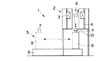
つぎに本発明の第1の実施の形態による永久磁石着磁装置1を図1にもとづき説明する。
図1は、永久磁石着磁装置1の概略側面図であって、永久磁石着磁装置1は、縦置きとした超電導磁石2と、その超電導コイル3を支持する荷重支持体4と、被着磁物搬送機構5と、を有する。
【0015】
超電導磁石2は、その超電導コイル3の中心部に、磁場発生室温空間6を有し、この磁場発生室温空間6は被着磁物7を挿入することができるだけの大きさないし容量を有している。
【0016】
荷重支持体4は、超電導磁石2の超電導コイル3を支持するもので、超電導磁石2と被着磁物7との間に作用する磁気力以上の耐力を有することが必要である。
【0017】
被着磁体搬送機構5は、往復搬送手段8(移送手段)と、この往復搬送手段8に取り付けるとともに被着磁物7を支持している往復用シリンダー9(往復挿入手段)と、を有する。すなわち、往復用シリンダー9のアーム部10の先端部に被着磁物7を取り付ける。
【0018】
こうした構成の永久磁石着磁装置1において、超電導磁石2を励磁して磁場発生室温空間6内に強磁場を発生させたままの状態で、被着磁体搬送機構5の往復搬送手段8により往復用シリンダー9を超電導磁石2の磁場発生室温空間6の下部まで移送し、ついでアーム部10を延ばして被着磁物7を磁場発生室温空間6に挿入する。
したがって、往復用シリンダー9は、被着磁物7の磁場発生室温空間6内への挿入時には、超電導コイル3による吸引力に対抗し、磁場発生室温空間6からの引出し時には、超電導コイル3による吸引力から脱出可能に保持するだけの力が必要となる。
【0019】
被着磁物7が磁場発生室温空間6内に挿入されることにより被着磁物7は着磁されて永久磁石となり、被着磁体搬送機構5によりもとの位置まで復動する。ここで、新たな被着磁物7をアーム部10に装着し、上述と同様の作業を繰り返す。
【0020】
かくして、超電導磁石2による強磁場を一度発生させれば、そのままの状態で被着磁物7を磁場発生室温空間6内に出し入れすればよいので、着磁作業の効率を向上させることができるとともに、とくに希土類磁石材料による永久磁石の性能を良好なものとすることができる。
【0021】
図2は、本発明の第2の実施の形態による永久磁石着磁装置20の概略側面図であって、永久磁石着磁装置20は、横置きとした超電導磁石2と、無端状の搬送手段21(被着磁物搬送機構)と、を有する。
【0022】
搬送手段21は、被着磁物7を超電導磁石2の方向に循環して移送するもので、ベルトコンベア22と、駆動モーター23と、被着磁物収容部材24と、を有する。
【0023】
ベルトコンベア22は、矩形状の搬送路を形成し、超電導コイル3の磁場発生室温空間6内を貫通して被着磁物収容部材24を循環させる。
【0024】
被着磁物収容部材24は、ベルトコンベア22に単一あるいは所定等間隔をあけてその複数個を固定するとともに、被着磁物7をこれに収容して、貫通した磁場発生室温空間6内に被着磁物7とともにこれを通過させる。
【0025】
こうした構成の永久磁石着磁装置20において、ベルトコンベア22の駆動により、被着磁物7を磁場発生室温空間6の一方の口から挿入し、その強磁場内にさらしつつ他方の口から引き出すようにする。
したがって、搬送手段21は、被着磁物7の磁場発生室温空間6内への進入時には、超電導コイル3による吸引力に対抗し、磁場発生室温空間6からの排出時には、超電導コイル3による吸引力から脱出可能に保持するだけの力が必要となる。
【0026】
かくして、超電導磁石2による強磁場を一度発生させれば、そのままの状態で被着磁物7を磁場発生室温空間6内に上流側から下流側へと一方向に通過させればよいので、着磁作業の効率を向上させることができるとともに、被着磁物収容部材24への被着磁物7の取付けおよび取出し作業が容易である。
【0027】
図3は、本発明の第3の実施の形態による永久磁石着磁装置30の概略側面図であって、永久磁石着磁装置30は、横置きとした超電導磁石2と、被着磁物搬送機構31と、を有する。
【0028】
被着磁物搬送機構31は、被着磁物収容部材32と、突っ張り部材33と、押出し手段34と、直線状搬送路35(搬送路手段)と、を有する。
【0029】
被着磁物収容部材32は、被着磁物7を収容し、突っ張り部材33とともに、押出し手段34により直線状搬送路35上を超電導磁石2の方向にこれを移送する。
【0030】
突っ張り部材33は、中央ロッド部36と、その左右一対のフランジ部37と、を有し、先行する被着磁物7の第1の被着磁物収容部材32と、続行する被着磁物7の第2の被着磁物収容部材32との間にこれを設ける。
したがって、この突っ張り部材33は、先行および続行する一対の被着磁物7の間を所定間隔に維持するとともに機械的に接続するものであって、被着磁物7が超電導磁石2の磁場中心に引き込まれようとする磁気力による圧縮力に耐え得る強度を持つものとする。
【0031】
押出し手段34は、たとえばシリンダーによりこれを構成し、そのアーム部38が、突っ張り部材33および被着磁物収容部材32を超電導磁石2の方向に連続的に順次押し出す。
【0032】
こうした構成の永久磁石着磁装置30において、先行する被着磁物7と続行する被着磁物7とは互いの間を突っ張り部材33により一定間隔とした拘束状態のまま連続的に直線状搬送路35上を超電導磁石2に順次供給されることになる。すなわち、被着磁物7を磁場発生室温空間6の上流口から挿入し、下流口から押し出すことになる。
しかして、この永久磁石着磁装置30においては、先行する被着磁物7に超電導磁石2が作用する磁気力と、続行する被着磁物7に働く磁気力が相殺し合うので、押出し手段34の駆動力を大幅に低減することができる。すなわち、図3の超電導コイル3内の被着磁物7に作用する磁気力を矢印で示すように、超電導コイル3の磁場発生室温空間6内に進入しようとする被着磁物7と、磁場発生室温空間6から抜け出ようとする被着磁物7との間には互いに反対方向の磁気力が作用し、被着磁物7自体に作用する磁気力は相殺されることになる。
したがって、押出し手段34はそれほど強大な駆動力を必要とせず、永久磁石着磁装置30全体の小型化が可能で、設備投資を少なくすることができるとともに、ランニングコストも押さえることができる。
【0033】
上記磁気力の相殺作用について図4にもとづき説明する。
図4は、超電導磁石2の超電導コイル3内の磁場強度の分布と、被着磁物7に働く磁気力との関係を示したグラフであって、横軸は超電導コイル3の中心軸上の位置(Z)を示す。グラフ中、黒丸データは、左側縦軸に示した磁場の強さ(磁束密度)で、超電導コイル3の中心部(Z=0)では5Tとなっている。白丸データは、右側縦軸に示した磁気力の大きさ(kgf)を示す。なお、具体的な数値は、被着磁物7をφ100mm−10mmtの円盤状のものとし、この円盤の容積の50%に強磁性体が入っているものとして計算した。
磁性体(被着磁物7)に働く磁気力は、その場所の磁場の勾配と、磁性体が持つ磁化との積によって決定される。たとえば、超電導コイル3における磁場中心(Z=0)では磁場の勾配がゼロで、磁気力はゼロとなり被着磁物7に作用しない。
【0034】
ここで、Zのマイナス側から被着磁物7を超電導磁石2に近づけて、その磁場空間に入れようとすると、グラフに示すように、プラス方向の磁気力が作用し、その大きさは、Z=−1.2m付近で最大約280kgfとなる。すなわち、被着磁物7は強大な力で超電導コイル3内に引き込まれようとするもので、この引き込み力に対抗する力で被着磁物7を支えて挿入する必要がある。
これに対して、磁場中心まできた被着磁物7をZのプラス方向に引き出すときには、グラフに示すように、マイナス方向の磁気力が作用し、その最大値は挿入時と同様に約280kgfとなるので、これに対抗する力で引き出すなり、あるいは押し出してやる必要がある。
かくして、連続するふたつの被着磁物7を突っ張り部材33を介在して機械的に接続した状態で押し込むようにしたので、上述の磁気力を相殺することが可能となり、押出し手段34としては直線状搬送路35上を被着磁物7、被着磁物収容部材32および突っ張り部材33の重量分だけを搬送する力を発揮すればよいことになる。
【0035】
なお、着磁処理が終了した被着磁物7、被着磁物収容部材32および突っ張り部材33を取り除くとともに、押出し手段34のアーム部38を引き込んだ状態で、図3に仮想線で示すように、新たな被着磁物7、被着磁物収容部材32および突っ張り部材33を直線状搬送路35上にセットする。このアーム部38の引き込み動作のときに直線状搬送路35上にすでにある被着磁物7、被着磁物収容部材32および突っ張り部材33の組は、上述のように互いに磁気力を相殺されているので、その現状位置にとどまっており、新たなセットの追加配置作業に支障はない。
【0036】
【発明の効果】
以上のように本発明によれば、超電導磁石の磁場を連続的に発生したまま、被着磁物を磁場空間に出し入れするだけで、着磁作業が完了するので、着磁の時間が短くなり、永久磁石の生産効率が向上する。
【図面の簡単な説明】
【図1】本発明の第1の実施の形態による永久磁石着磁装置1の概略側面図である。
【図2】本発明の第2の実施の形態による永久磁石着磁装置20の概略側面図である。
【図3】本発明の第3の実施の形態による永久磁石着磁装置30の概略側面図である。
【図4】同、超電導磁石2の超電導コイル3内の磁場強度の分布と、被着磁物7に働く磁気力との関係を示したグラフである。
【符号の説明】
1 永久磁石着磁装置(第1の実施の形態、図1)
2 超電導磁石
3 超電導磁石2の超電導コイル
4 荷重支持体
5 被着磁体搬送機構
6 超電導コイル3の磁場発生室温空間
7 被着磁物
8 往復搬送手段
9 往復用シリンダー
10 往復用シリンダー9のアーム部
20 永久磁石着磁装置(第2の実施の形態、図2)
21 無端状の搬送手段(被着磁体搬送機構)
22 ベルトコンベア
23 駆動モーター
24 被着磁物収容部材
30 永久磁石着磁装置(第3の実施の形態、図3)
31 被着磁物搬送機構
32 被着磁物収容部材
33 突っ張り部材
34 押出し手段
35 直線状搬送路(搬送路手段)
36 突っ張り部材33の中央ロッド部
37 突っ張り部材33の左右一対のフランジ部
38 押出し手段34のアーム部[0001]
BACKGROUND OF THE INVENTION
The present invention relates to a permanent magnet magnetizing apparatus, and more particularly to a permanent magnet magnetizing apparatus using a superconducting magnet.
[0002]
[Prior art]
Conventionally, permanent magnets such as rare earth magnets have to be magnetized by applying a strong magnetic field of 1 to 3 T (Tesla) to the object to be magnetized in the final process of production.
Conventionally, a pulse electromagnet has been used for this magnetization operation. That is, magnetization is performed by applying a magnetic field with a current of several hundred amperes by this pulse electromagnet for about 0.1 second, for example, which is a practical means in terms of energy. It should be noted that it is practically difficult to put the magnetic object in and out of the magnetic field within this short time while the magnetic field is constantly generated by the electromagnet, and the pulsed magnet can be used to supply the magnetic field in pulses. It has been broken.
However, with the development of rare earth magnet materials in recent years, the magnetic field strength necessary for the magnetization has been improved. On the other hand, it is difficult to obtain the necessary strong magnetic field with the pulse electromagnet, and the economic efficiency for magnetization is low. There is a problem of lowering.
In addition, in the magnetizing operation using the pulse electromagnet, there is a problem that the permanent magnet cannot be magnetized due to the eddy current flowing in the case when the permanent magnet is put in another metal case.
[0003]
On the other hand, focusing on a superconducting magnet that can obtain a stronger magnetic field than a pulsed electromagnet, a method of magnetizing a permanent magnet by a magnetic field generated by the superconducting magnet has also been attempted. However, the superconducting magnet requires several minutes to several tens of minutes for raising and lowering its magnetic field, and there is a problem that the magnetic field cannot be supplied in the form of pulses like a pulsed electromagnet.
[0004]
[Problems to be solved by the invention]
The present invention has been considered in view of the above problems, and an object of the present invention is to provide a permanent magnet magnetizing apparatus capable of performing practical magnetization using a superconducting magnet.
[0005]
Another object of the present invention is to provide a permanent magnet magnetizing apparatus capable of magnetizing an object to be magnetized with a strong magnetic field generated.
[0006]
It is another object of the present invention to provide a permanent magnet magnetizing apparatus that can greatly improve the magnetizing performance and efficiency.
[0007]
It is another object of the present invention to provide a permanent magnet magnetizing apparatus capable of continuously transferring a magnetized object to a superconducting magnet and reducing the driving force thereof.
[0008]
[Means for Solving the Problems]
That is, the present invention focuses on using a superconducting magnet as the magnetizing means, leaving the magnetic field generated by the superconducting magnet to be generated, and providing a magnetized material transport mechanism for supplying the magnetized material. A permanent magnet magnetizing apparatus for placing a magnetized object in a magnetic field of an electromagnet and magnetizing it to make a permanent magnet, wherein a superconducting magnet is employed as the electromagnet, and the superconducting magnet A permanent magnet magnetizing apparatus comprising a magnetized object transporting mechanism for supplying the magnetized object so as to be taken in and out intermittently in a magnetic field generating room temperature space formed in the above.
[0009]
The adherend magnet transport mechanism includes a transfer means for transferring the adherend in the direction of the superconducting magnet, and the adherend in the magnetic field generating room temperature when the transfer means is temporarily stopped. And a reciprocating insertion means such as a reciprocating cylinder for reciprocating.
[0010]
The adherend magnet transport mechanism moves the adherend in the direction of the superconducting magnet, and moves the adherend from the upstream side to the downstream side in the magnetic field generation room temperature space. It can have conveying means, such as a bell to convey and a conveyor.
[0011]
The magnetized object transport mechanism includes a magnetized object accommodating member that accommodates the magnetized object, a first magnetized object accommodating member of the preceding magnetized object, and the magnetized magnet that continues. A tension member provided between the object and the second magnetized object housing member, an extruding means for continuously and sequentially extruding the strut member and the adherend magnet object accommodating member in the direction of the superconducting magnet, and the pushing means And a conveying path means for passing the stretched member and the adherend magnet housing member pushed out from the upstream side to the downstream side in the magnetic field generation room temperature space.
[0012]
In the permanent magnet magnetizing apparatus according to the present invention, a superconducting magnet is used as the magnetizing means, and a strong magnetic field is kept generated, and the magnetized material is supplied into the constant strong magnetic field. Since the adherend magnet transport mechanism is provided, the adherend can be intermittently supplied into the strong magnetic field without supplying a pulsed magnetic field unlike a pulse electromagnet.
Therefore, the magnetizing operation can be completed by simply putting the magnetized object in and out of the magnetic field space (magnetic field generating room temperature space) while the strong magnetic field generated by the superconducting magnet is continuously generated. The production efficiency improves with the performance of the magnet.
[0013]
In particular, a tension member is provided between the first magnetized object housing member of the preceding magnetized object and the second magnetized object accommodating member of the continued magnetized object, and this thrust member is provided by the pushing means. And the magnetized object housing member are sequentially and sequentially pushed in the direction of the superconducting magnet to cancel the magnetic force between the preceding magnetized object and the continued magnetized substance, The supply pushing force of the adherend can be reduced.
[0014]
DETAILED DESCRIPTION OF THE INVENTION
Next, a permanent magnet magnetizing apparatus 1 according to a first embodiment of the present invention will be described with reference to FIG.
FIG. 1 is a schematic side view of a permanent magnet magnetizing apparatus 1. The permanent magnet magnetizing apparatus 1 includes a
[0015]
The
[0016]
The
[0017]
The adherend magnetic
[0018]
In the permanent magnet magnetizing apparatus 1 having such a configuration, the
Therefore, the reciprocating
[0019]
When the
[0020]
Thus, once a strong magnetic field is generated by the
[0021]
FIG. 2 is a schematic side view of a permanent
[0022]
The conveying means 21 circulates and transfers the
[0023]
The
[0024]
The magnetized
[0025]
In the permanent
Therefore, the conveying
[0026]
Thus, once the strong magnetic field generated by the
[0027]
FIG. 3 is a schematic side view of a permanent
[0028]
The adherend magnetic
[0029]
The adherend
[0030]
The
Therefore, the
[0031]
The push-out means 34 is constituted by, for example, a cylinder, and the
[0032]
In the permanent
Thus, in this permanent
Therefore, the pushing
[0033]
The magnetic force canceling action will be described with reference to FIG.
FIG. 4 is a graph showing the relationship between the distribution of the magnetic field intensity in the
The magnetic force acting on the magnetic body (the magnetized object 7) is determined by the product of the gradient of the magnetic field at that location and the magnetization of the magnetic body. For example, at the magnetic field center (Z = 0) in the
[0034]
Here, when the object to be magnetized 7 is brought close to the
On the other hand, when the
Thus, since two continuous
[0035]
As shown by the phantom line in FIG. 3, the
[0036]
【The invention's effect】
As described above, according to the present invention, the magnetizing operation is completed simply by taking the magnetic object into and out of the magnetic field space while the magnetic field of the superconducting magnet is continuously generated. The production efficiency of permanent magnets is improved.
[Brief description of the drawings]
FIG. 1 is a schematic side view of a permanent magnet magnetizing apparatus 1 according to a first embodiment of the present invention.
FIG. 2 is a schematic side view of a permanent
FIG. 3 is a schematic side view of a permanent
4 is a graph showing the relationship between the distribution of the magnetic field strength in the
[Explanation of symbols]
1 Permanent magnet magnetizing apparatus (first embodiment, FIG. 1)
2
21 Endless conveying means (adhered magnet conveying mechanism)
22
31 Adhered
36
Claims (1)
前記電磁石として超電導磁石を採用するとともに、
この超電導磁石に形成した磁場発生室温空間内に前記被着磁物を断続的に出し入れするように供給する被着磁物搬送機構を設け、
この被着磁物搬送機構は、
前記被着磁物を収容する被着磁物収容部材と、
先行する前記被着磁物の第1の被着磁物収容部材と、続行する前記被着磁物の第2の被着磁物収容部材との間に設ける突っ張り部材と、
シリンダーおよびそのアーム部を有するとともに、このアーム部がこの突っ張り部材および前記被着磁物収容部材を前記超電導磁石の方向に連続的に順次押し出す押出し手段と、
この押出し手段により押し出された前記突っ張り部材および前記被着磁物収容部材を前記磁場発生室温空間内に上流側から下流側に通過させる搬送路手段と、を有するとともに、
前記押出し手段は、前記アーム部を引き込んだ状態で新たな被着磁物、被着磁物収容部材および突っ張り部材を前記搬送路手段上にセット可能とすることを特徴とする永久磁石着磁装置。A permanent magnet magnetizing device for placing a magnetic object in a magnetic field of an electromagnet and magnetizing the magnetized material into a permanent magnet,
While adopting a superconducting magnet as the electromagnet,
A magnetic object transport mechanism for supplying the magnetic material to be intermittently taken in and out of the magnetic field generation room temperature space formed in the superconducting magnet ;
This adherend magnetic material transport mechanism
A magnetized object housing member that accommodates the magnetized material;
A tension member provided between the first magnetic object housing member of the preceding magnetic object to be preceded and the second magnetic object housing member of the magnetic object to be continued,
An extruding means that has a cylinder and its arm part, and this arm part sequentially and sequentially pushes out the tension member and the adherend magnetic material accommodating member in the direction of the superconducting magnet;
Transport path means for passing the stretched member and the adherend magnetic material accommodating member pushed out by the pushing means from the upstream side to the downstream side in the magnetic field generation room temperature space, and
A permanent magnet magnetizing apparatus characterized in that the pushing means can set a new magnetized object, a magnetized object accommodating member and a tension member on the conveying path means in a state where the arm portion is retracted. .
Priority Applications (1)
| Application Number | Priority Date | Filing Date | Title |
|---|---|---|---|
| JP15897799A JP3940980B2 (en) | 1999-06-07 | 1999-06-07 | Permanent magnet magnetizer |
Applications Claiming Priority (1)
| Application Number | Priority Date | Filing Date | Title |
|---|---|---|---|
| JP15897799A JP3940980B2 (en) | 1999-06-07 | 1999-06-07 | Permanent magnet magnetizer |
Publications (2)
| Publication Number | Publication Date |
|---|---|
| JP2000348937A JP2000348937A (en) | 2000-12-15 |
| JP3940980B2 true JP3940980B2 (en) | 2007-07-04 |
Family
ID=15683522
Family Applications (1)
| Application Number | Title | Priority Date | Filing Date |
|---|---|---|---|
| JP15897799A Expired - Fee Related JP3940980B2 (en) | 1999-06-07 | 1999-06-07 | Permanent magnet magnetizer |
Country Status (1)
| Country | Link |
|---|---|
| JP (1) | JP3940980B2 (en) |
Cited By (1)
| Publication number | Priority date | Publication date | Assignee | Title |
|---|---|---|---|---|
| CN105590718A (en) * | 2016-03-11 | 2016-05-18 | 东莞市东鸿自动化科技有限公司 | Simple magnetizing and magnetic strip insertion method |
Families Citing this family (3)
| Publication number | Priority date | Publication date | Assignee | Title |
|---|---|---|---|---|
| JP4496757B2 (en) * | 2003-10-28 | 2010-07-07 | アイシン・エィ・ダブリュ株式会社 | Magnetizing apparatus and magnetizing method |
| JP5144790B2 (en) * | 2011-06-15 | 2013-02-13 | 智之 河内 | Joint mechanism manufacturing method using electromagnetic induction in dolls and animal and plant models |
| CN115472380B (en) * | 2022-09-30 | 2023-03-17 | 东莞市强联磁铁有限公司 | Magnet magnetizing process and equipment thereof |
-
1999
- 1999-06-07 JP JP15897799A patent/JP3940980B2/en not_active Expired - Fee Related
Cited By (1)
| Publication number | Priority date | Publication date | Assignee | Title |
|---|---|---|---|---|
| CN105590718A (en) * | 2016-03-11 | 2016-05-18 | 东莞市东鸿自动化科技有限公司 | Simple magnetizing and magnetic strip insertion method |
Also Published As
| Publication number | Publication date |
|---|---|
| JP2000348937A (en) | 2000-12-15 |
Similar Documents
| Publication | Publication Date | Title |
|---|---|---|
| EP0522950B1 (en) | Linear magnetization mover motor due to linear force resulting from the interaction between magnetostatic induction element and electromagnetic coil | |
| NO20060618L (en) | Device for transporting particles of a magnetic material and tool comprising such a device | |
| US4488962A (en) | Magnetic filtering apparatus | |
| JP3940980B2 (en) | Permanent magnet magnetizer | |
| US6062393A (en) | Process and apparatus for separating particles of different magnetic susceptibilities | |
| GB2367949B (en) | Controlling method of superconductor magnetic field application apparatus and nuclear magnetic resonance apparatus and superconducting magnet apparatus | |
| WO1992009396A1 (en) | Core treating apparatus and method | |
| JPH05129132A (en) | Magnetization equipment for anisotropic polar magnet | |
| JPS5593705A (en) | Work conveyor | |
| EP1457788A3 (en) | MRI pulsed readout magnet | |
| CN219738677U (en) | Conveying type magnetizing device | |
| CN209880308U (en) | Automatic manufacturing equipment for magnet magnetization | |
| JP2001044032A (en) | Magnetizing method for high-temperature- superconducting bulk magnet mounted on superconducting magnet-levitation railway vehicle | |
| CN101226813B (en) | V-shaped demagnetizing device for macrotype bearing ring odd magnetic pole unit and demagnetizing method | |
| JP5326357B2 (en) | Magnetization method of permanent magnet | |
| JP4732812B2 (en) | A system and method for magnetizing blocks on a magnet assembly of an MRI apparatus. | |
| JPS6034336Y2 (en) | magnetic filter | |
| CA2466991A1 (en) | Magnetic holding field for cryogenically accumulated polarized 129xenon | |
| JPS6423098A (en) | Lancher for flying object | |
| JPS60212253A (en) | Magnetic separator for iron pieces mixed in magnetite ore | |
| JPS6453511A (en) | Magnetization of permanent magnet | |
| JPH0761631A (en) | Magnetic sheet transfer device | |
| WO2004099807A1 (en) | The assembling method and conveying tool for magnetic device | |
| CN116037515A (en) | Automatic detection equipment and detection method thereof | |
| JPS60131174A (en) | Wall-surface walking machine |
Legal Events
| Date | Code | Title | Description |
|---|---|---|---|
| A131 | Notification of reasons for refusal |
Free format text: JAPANESE INTERMEDIATE CODE: A131 Effective date: 20060328 |
|
| A521 | Written amendment |
Free format text: JAPANESE INTERMEDIATE CODE: A523 Effective date: 20060515 |
|
| TRDD | Decision of grant or rejection written | ||
| A01 | Written decision to grant a patent or to grant a registration (utility model) |
Free format text: JAPANESE INTERMEDIATE CODE: A01 Effective date: 20070320 |
|
| A61 | First payment of annual fees (during grant procedure) |
Free format text: JAPANESE INTERMEDIATE CODE: A61 Effective date: 20070322 |
|
| R150 | Certificate of patent or registration of utility model |
Free format text: JAPANESE INTERMEDIATE CODE: R150 |
|
| S531 | Written request for registration of change of domicile |
Free format text: JAPANESE INTERMEDIATE CODE: R313531 |
|
| FPAY | Renewal fee payment (event date is renewal date of database) |
Free format text: PAYMENT UNTIL: 20100413 Year of fee payment: 3 |
|
| R350 | Written notification of registration of transfer |
Free format text: JAPANESE INTERMEDIATE CODE: R350 |
|
| FPAY | Renewal fee payment (event date is renewal date of database) |
Free format text: PAYMENT UNTIL: 20100413 Year of fee payment: 3 |
|
| FPAY | Renewal fee payment (event date is renewal date of database) |
Free format text: PAYMENT UNTIL: 20110413 Year of fee payment: 4 |
|
| FPAY | Renewal fee payment (event date is renewal date of database) |
Free format text: PAYMENT UNTIL: 20120413 Year of fee payment: 5 |
|
| FPAY | Renewal fee payment (event date is renewal date of database) |
Free format text: PAYMENT UNTIL: 20120413 Year of fee payment: 5 |
|
| FPAY | Renewal fee payment (event date is renewal date of database) |
Free format text: PAYMENT UNTIL: 20130413 Year of fee payment: 6 |
|
| LAPS | Cancellation because of no payment of annual fees |