JP3931666B2 - Power line carrier communication equipment - Google Patents
Power line carrier communication equipment Download PDFInfo
- Publication number
- JP3931666B2 JP3931666B2 JP2002015058A JP2002015058A JP3931666B2 JP 3931666 B2 JP3931666 B2 JP 3931666B2 JP 2002015058 A JP2002015058 A JP 2002015058A JP 2002015058 A JP2002015058 A JP 2002015058A JP 3931666 B2 JP3931666 B2 JP 3931666B2
- Authority
- JP
- Japan
- Prior art keywords
- power line
- signal
- wavelet
- data
- subcarrier
- Prior art date
- Legal status (The legal status is an assumption and is not a legal conclusion. Google has not performed a legal analysis and makes no representation as to the accuracy of the status listed.)
- Expired - Lifetime
Links
Images
Landscapes
- Cable Transmission Systems, Equalization Of Radio And Reduction Of Echo (AREA)
Description
【0001】
【発明の属する技術分野】
本発明は、電力線を利用してデータ伝送を行う電力線搬送通信装置に関するものである。
【0002】
【従来の技術】
電力線搬送通信装置は、各家庭に既にある電力線をネットワーク伝送路として利用することで、すぐに家庭内通信網が構築できることが大きな特長である。しかしながら、電力線搬送通信装置は、平衡度の悪い電力線を通信媒体として信号を送受信するため、電力線からの漏洩電力が大きい。また、高速電力線搬送通信に必要な周波数帯域では、アマチュア無線や短波放送などが既に周波数帯域を利用しているため、これら既存通信システムに対する電力線搬送通信装置からの干渉が問題となる。各国で定められた電波法や通信法による規制事項には、使用周波数帯や許容電界強度といった項目について多種多様な制限が加えられており、これらに準じて通信に利用する周波数帯域を制限することが必要となる。また、電力線搬送通信装置の通信媒体となる一般の電力線には多種多様な電気機器が接続されるため、通信性能を左右する電力線のインピーダンス、電力線上の雑音、伝送中の信号減衰量などは、各家庭の電灯線の配線状態により個々に違い、電力線に接続されている電気機器によっても変化し、さらにその特性は周波数によっても大きく異なる。
【0003】
このように、電力線を通信媒体とした電力線搬送通信では、電力線のインピーダンス変動や雑音、信号減衰などによる通信障害や、他の既存通信システムへの妨害が懸念される。このため、一時的な通信障害をもつ周波数帯の使用を回避する仕組みと各国の法規制に柔軟に対応するための仕組み、すなわち通信に使用する周波数帯と使用しない周波数帯とをきちんと区別し、さらに、それらを容易に変更できることが必要不可欠となる。この課題に対して、従来からマルチキャリア伝送方式を用いた提案が多く行われている。
【0004】
電力線を通信媒体とした従来の電力線搬送通信装置としては、例えば特開2000−165304号公報に記載されている装置がある。
【0005】
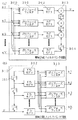
図25は、特開2000−165304号公報に記載された電力線通信装置を示すブロック図である。
【0006】
図25において、600は電力線搬送通信装置、601はデータ分割器、602はQAM(Quadrature Amplitude Modulation)エンコーダ、603は逆フーリエ変換器、604は並直列変換器、605はD/A変換器、606は低域通過フィルタ、607は電力線結合回路、608は電力線、609は低域通過フィルタ、610はA/D変換器、611直並列変換器、612はフーリエ変換器、613はQAMデコーダ、614はデータ合成器である。
【0007】
図25の構成を見て明らかなように、特開2000−165304号公報に記載されている電力線搬送通信装置は、フーリエ変換を利用した直交周波数分割多重(Orthogonal Frequency Division Multiplexing)伝送(以下、「OFDM伝送」という)方式を電力線搬送通信に適用したものである。
【0008】
次に、図25の電力線搬送通信装置について、その動作を説明する。
【0009】
電力線608への送信動作については、まず、送信データがデータ分割器601に入力され、複数のサブキャリアに割り当てるためのビット列が生成される。次に、このビット列がQAMエンコーダ602によって複素信号に変換され、逆フーリエ変換器603、並直列変換器604を介して、周波数分割多重化された時間サンプル系列が生成される。この時間サンプル系列は、D/A変換器605、低域通過フィルタ606および電力線結合回路607を介して、電力線608へ送信される。逆に、電力線608からの受信動作においては、A/D変換器610は、電力線結合回路607と低域通過フィルタ609を介して受信したアナログ信号(電力線通信用信号)をディジタル信号に変換する。次に、このディジタル信号は、直並列変換器611、フーリエ変換器612を介して、各周波数毎のQAMコードに変換される。そして、この各QAMコードをQAMデコーダ613によってそれぞれ復調し、この復調されたデータをデータ合成器614によって合成する。
【0010】
以上のように、この電力線搬送通信装置によれば、OFDM伝送方式によって送信信号を複数の周波数スペクトルをもつ搬送波(サブキャリア)で構成し、電力線の雑音や減衰量の周波数特性に従って、それらの各サブキャリアに重畳する情報量を適応的に変化させることにより、周波数を高効率で利用し、伝送速度を向上させて通信できるという効果がある。また、任意のサブキャリアを使用しないように送信側の回路を制御することによって、伝送路環境が劣悪な周波数帯での通信は避け、伝送路の状態が良好な周波数帯で積極的に多値変調を行うことによって、安定した通信を行うことが可能となっている。さらに、この制御によって、各国の法規制に準じた信号を出力することもできる。
【0011】
【発明が解決しようとする課題】
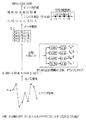
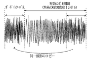
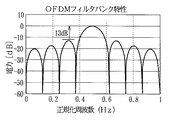
しかしながら、上記従来の電力線搬送通信装置では、以下のような問題点があった。これを図26、図27を用いて説明する。図26はガードインターバルの仕組みを示すグラフであり、図27はOFDMのフィルタバンク特性を示すグラフである。
【0012】
従来の電力線搬送通信装置では、電力線を使用した通信においてフーリエ変換を用いたOFDM伝送が行われているが、フーリエ変換を用いたOFDM伝送はマルチパスの影響を低減するために、図26に示すようなガードインターバル区間を信号区間に設ける必要がある。ガードインターバル区間は情報伝送から見れば冗長であり、その分、周波数利用効率を低下させる。また、ガードインターバル区間は短いほど伝送効率は向上するが、受信側でマルチパスの影響を受け易くなり、誤り率特性の劣化を招く。電力線通信環境はマルチパスによる遅延波の遅延時間が特に大きいため、ガードインターバル区間を大きくする必要があり、結果として伝送速度を犠牲にする割合が著しく大きなものとなる。また、既存システムへの干渉回避について、従来の方法では、サブキャリアに対してデータを割り当てない(マスクする)ことにより、既存システムの使用帯域における信号の振幅を理論的にゼロにする方式がとられる。図19(後述する)に、OFDM方式で使用しない帯域に対してマスクを行った例を示す。確かにマスクされたサブキャリアの振幅は出ていないが、隣接するサブキャリアのサイドローブの漏込みにより、13dB程度の減衰しか得られない。OFDMの場合は矩形波を窓関数に使用してフーリエ変換を行っているため、図27に示すように、メインローブに対するサイドローブの減衰が13dB程度しか得られない。そのため既存通信システムへの妨害を十分に小さくすることができない。特に高速電力線搬送通信が使用する周波数帯域には、アマチュア無線や短波放送など受信感度の高い無線システムが既に多数存在する。これら既存システムへの影響を回避するには、既存システムが使用している帯域に対しては送信しないようにする必要性がある。このため、従来の方法では新たに帯域阻止フィルタを設置する必要があった。この帯域阻止フィルタが回路規模の増大を招き、また高速で動作する必要性があることから消費電力を増大させる要因の一つとなっている。
【0013】
この電力線搬送通信装置では、伝送速度劣化の要因となるガードインターバルを排除しても通信が可能で、各国の電波法規制に応じて通信に利用する周波数帯域を限定し、回路規模増大の要因となる帯域阻止フィルタを設置することなしに既存システムの使用帯域において十分な減衰量を得ることが要求されている。
【0014】
本発明は、このような要求を満たすため、伝送速度劣化の要因となるガードインターバルを排除しても通信が可能で、各国の電波法規制に応じて通信に利用する周波数帯域を限定し、回路規模増大の要因となる帯域阻止フィルタを設置することなしに既存システムの使用帯域において十分な減衰量を得ることのできる電力線搬送通信装置を提供することを目的とする。
【0015】
【課題を解決するための手段】
上記課題を解決するために本発明の電力線搬送通信装置は、送信部と、受信部と、送信部からの信号を電力線に対して電力線通信用信号として重畳すると共に電力線から電力線通信用信号のみを抽出する電力線結合回路と、送信部と受信部の各構成要素を制御する制御部とを有し、複数のサブキャリアを用いて通信を行う電力線搬送通信装置であって、送信部は、入力される送信データから複数のビット列を生成してビット列を各サブキャリアの信号点に写像する信号点写像器と、信号点写像器により写像された各サブキャリアの信号点データに基づき互いに直交したウェーブレット波形をもって各サブキャリアの変調を行うことにより時間波形系列データの生成を行うウェーブレット逆変換器と、ウェーブレット逆変換器による時間波形系列データをアナログ変換するD/A変換器とを有し、受信部は、電力線結合回路により電力線から抽出された電力線通信用信号をディジタル変換してサンプリング系列波形データを得るA/D変換器と、A/D変換器によるサンプリング系列波形データを各サブキャリアの信号点データに変換するウェーブレット変換器と、ウェーブレット変換器から出力される複数の信号点データを逆写像して信号点写像器で写像されたビット列を判別し受信データ系列として合成するシンボル判定器とを有し、前記ウェーブレット逆変換器と前記ウェーブレット変換器は、重複係数に応じたフィルタ長の異なる複数のフィルタ係数パターンを有し、送信部から送信される電力線通信信号や、伝送路の変動、受信レベル等の受信条件に応じて、前記複数のフィルタ係数パターンの中から適切なフィルタ係数パターンを選択する構成を備えている。
【0016】
これにより、伝送速度劣化の要因となるガードインターバルを排除しても通信が可能で、各国の電波法規制に応じて通信に利用する周波数帯域を限定し、回路規模増大の要因となる帯域阻止フィルタを設置することなしに既存システムの使用帯域において十分な減衰量を得ることができ、さらに、伝送路の雑音状態が良好な場合の演算量を低減することができ、受信時の消費電力を削減することができ、また、雑音状態が劣悪な場合においても安定した受信を行うことができるという作用を有する電力線搬送通信装置が得られる。
【0017】
【発明の実施の形態】
本発明の請求項1に記載の電力線搬送通信装置は、送信部と、受信部と、前記送信部からの信号を電力線に対して電力線通信用信号として重畳すると共に電力線から電力線通信用信号のみを抽出する電力線結合回路と、前記送信部と前記受信部の各構成要素を制御する制御部とを有し、複数のサブキャリアを用いて通信を行う電力線搬送通信装置であって、前記送信部は、入力される送信データから複数のビット列を生成して前記ビット列を各サブキャリアの信号点に写像する信号点写像器と、前記信号点写像器により写像された各サブキャリアの信号点データに基づき互いに直交したウェーブレット波形をもって各サブキャリアの変調を行うことにより時間波形系列データの生成を行うウェーブレット逆変換器と、前記ウェーブレット逆変換器による時間波形系列データをアナログ変換するD/A変換器とを有し、前記受信部は、前記電力線結合回路により電力線から抽出された電力線通信用信号をディジタル変換してサンプリング系列波形データを得るA/D変換器と、前記A/D変換器によるサンプリング系列波形データを各サブキャリアの信号点データに変換するウェーブレット変換器と、前記ウェーブレット変換器から出力される複数の信号点データを逆写像して前記信号点写像器で写像されたビット列を判別し受信データ系列として合成するシンボル判定器とを有し、前記ウェーブレット逆変換器と前記ウェーブレット変換器は、重複係数に応じたフィルタ長の異なる複数のフィルタ係数パターンを有し、送信部から送信される電力線通信信号や、伝送路の変動、受信レベル等の受信条件に応じて、前記複数のフィルタ係数パターンの中から適切なフィルタ係数パターンを選択することを特徴とする電力線搬送通信装置である。
【0018】
この構成により、OFDM伝送方式で必要であったガードインターバルという冗長な信号部分が必要でなくなり、周波数利用効率を向上することができ、また、複素演算を必要とするフーリエ変換を実部の演算のみで行うウェーブレット変換で実現しているので、演算量を削減することができ、回路規模を低減することができるという作用を有する。また、伝送速度劣化の要因となるガードインターバルを排除しても通信が可能であり、各国の電波法規制に応じて通信に利用する周波数帯域を限定し、回路規模増大の要因となる帯域阻止フィルタを設置することなしに既存システムの使用帯域において十分な減衰量を得ることができるという作用を有する。さらに、伝送路の雑音状態が良好な場合の演算量を低減することができ、受信時の消費電力を削減することができ、また、雑音状態が劣悪な場合においても安定した受信を行うことができるという作用を有する。
【0019】
請求項2に記載の電力線搬送通信装置は、送信部と、受信部と、前記送信部からの信号を電力線に対して電力線通信用信号として重畳すると共に電力線から電力線通信用信号のみを抽出する電力線結合回路と、前記送信部と前記受信部の各構成要素を制御する制御部とを有し、複数のサブキャリアを用いて通信を行う電力線搬送通信装置であって、前記送信部は、入力される送信データから複数のビット列を生成して前記ビット列を各サブキャリアの信号点に写像する信号点写像器と、前記信号点写像器により写像された各サブキャリアの信号点データに基づき互いに直交したウェーブレット波形をもって各サブキャリアの変調を行うことにより時間波形系列データの生成を行うウェーブレット逆変換器と、前記ウェーブレット逆変換器から出力される時間波形系列データを任意の搬送波周波数帯域に周波数シフトする送信用周波数変換器と、前記送信用周波数変換器から出力される時間波形系列データをアナログ変換するD/A変換器とを有し、前記受信部は、前記電力線結合回路により電力線から抽出された電力線通信用信号をディジタル変換してサンプリング系列波形データを得るA/D変換器と、前記A/D変換器によるサンプリング系列波形データをベースバンド帯域へ周波数シフトしてベースバンド信号系列を得る受信用周波数変換器と、前記受信用周波数変換器から出力されたベースバンド信号系列を各サブキャリアの信号点データに変換するウェーブレット変換器と、前記ウェーブレット変換器から出力される複数の信号点データを逆写像して前記信号点写像器で写像されたビット列を判別し受信データ系列として合成するシンボル判定器とを有し、前記ウェーブレット逆変換器と前記ウェーブレット変換器は、重複係数に応じたフィルタ長の異なる複数のフィルタ係数パターンを有し、送信部から送信される電力線通信信号や、伝送路の変動、受信レベル等の受信条件に応じて、前記複数のフィルタ係数パターンの中から適切なフィルタ係数パターンを選択することを特徴とする電力線搬送通信装置である。
【0020】
この構成により、OFDM伝送方式で必要であったガードインターバルという冗長な信号部分が必要でなくなり、周波数利用効率を向上することができ、また、複素演算を必要とするフーリエ変換を実部の演算のみで行うウェーブレット変換で実現しているので、演算量を削減することができ、回路規模を低減することができるという作用を有する。また、伝送速度劣化の要因となるガードインターバルを排除しても通信が可能であり、各国の電波法規制に応じて通信に利用する周波数帯域を限定し、回路規模増大の要因となる帯域阻止フィルタを設置することなしに既存システムの使用帯域において十分な減衰量を得ることができるという作用を有する。さらに、任意の周波数帯へのシフトが可能になるので、例えば宅内と宅外で使用できる周波数帯が各国で異なる場合についても容易に対応することができ、ベースバンド伝送方式のみで対応するよりも、回路規模をさらに抑えることができるという作用を有する。さらに、伝送路の雑音状態が良好な場合の演算量を低減することができ、受信時の消費電力を削減することができ、また、雑音状態が劣悪な場合においても安定した受信を行うことができるという作用を有する。
【0021】
請求項3に記載の電力線搬送通信装置は、送信部と、受信部と、前記送信部からの信号を電力線に対して電力線通信用信号として重畳すると共に電力線から電力線通信用信号のみを抽出する電力線結合回路と、前記送信部と前記受信部の各構成要素を制御する制御部とを有し、複数のサブキャリアを用いて通信を行う電力線搬送通信装置であって、前記送信部は、入力される送信データから複数のビット列を生成して前記ビット列を各サブキャリアの複素信号点に写像する信号点写像器と、前記信号点写像器により写像された各サブキャリアの複素信号点データに基づき互いに直交したウェーブレット波形をもって各サブキャリアの変調を行うことにより複素時間波形系列データの生成を行うウェーブレット逆変換器と、前記ウェーブレット逆変換器から出力される複素時間波形系列データを直交変調することにより任意の搬送波周波数帯域に周波数シフトする直交変調器と、前記直交変調器から出力される複素時間波形系列データをアナログ変換するD/A変換器とを有し、前記受信部は、前記電力線結合回路により電力線から抽出された電力線通信用信号をディジタル変換してサンプリング系列波形データを得るA/D変換器と、前記A/D変換器によるサンプリング系列波形データをベースバンド帯域へ周波数シフトしてベースバンド信号系列を得る直交復調器と、前記直交復調器から出力されたベースバンド信号系列を各サブキャリアの信号点データに変換するウェーブレット変換器と、前記ウェーブレット変換器から出力される複数の信号点データを逆写像して前記信号点写像器で写像されたビット列を判別し受信データ系列として合成するシンボル判定器とを有し、前記ウェーブレット逆変換器と前記ウェーブレット変換器は、重複係数に応じたフィルタ長の異なる複数のフィルタ係数パターンを有し、送信部から送信される電力線通信信号や、伝送路の変動、受信レベル等の受信条件に応じて、前記複数のフィルタ係数パターンの中から適切なフィルタ係数パターンを選択することを特徴とする電力線搬送通信装置である。
【0022】
この構成により、OFDM伝送方式で必要であったガードインターバルという冗長な信号部分が必要でなくなり、周波数利用効率を向上することができ、また、複素演算を必要とするフーリエ変換を実部の演算のみで行うウェーブレット変換で実現しているので、演算量を削減することができ、回路規模を低減することができるという作用を有する。また、伝送速度劣化の要因となるガードインターバルを排除しても通信が可能であり、各国の電波法規制に応じて通信に利用する周波数帯域を限定し、回路規模増大の要因となる帯域阻止フィルタを設置することなしに既存システムの使用帯域において十分な減衰量を得ることができるという作用を有する。さらに、直交変復調により複素領域の信号点データを使用できるので、さらに周波数利用効率を向上させることができるという作用を有する。さらに、伝送路の雑音状態が良好な場合の演算量を低減することができ、受信時の消費電力を削減することができ、また、雑音状態が劣悪な場合においても安定した受信を行うことができるという作用を有する。
【0023】
請求項4に記載の電力線搬送通信装置は、請求項1乃至3のいずれか1に記載の電力線搬送通信装置において、ウェーブレット逆変換器とウェーブレット変換器は、完全再構成あるいは疑似完全再構成の重複直交変換機能または一般化重複直交変換機能を有することとしたものである。
【0024】
この構成により、ウェーブレット変換を実現するフィルタバンク回路の全フィルタに対して直線位相特性を持たすことができるので、フィルタバンクに必要な乗算器の個数を半分にすることができ、回路規模を小さくすることができるという作用を有する。また、各サブキャリアの周波数特性をメインローブを中心に急峻に設計できるので、受信時において他のサブキャリアからの干渉や帯域外の雑音による影響を低減することができるという作用を有する。
【0025】
請求項5に記載の電力線搬送通信装置は、請求項1乃至3のいずれか1に記載の電力線搬送通信装置において、ウェーブレット逆変換器とウェーブレット変換器は、変調重複変換機能または拡張変調重複変換機能を有することとしたものである。
【0026】
この構成により、各サブキャリアの再度ろ周波数特性をメインローブを中心に更に急峻に設計できるので、電力線搬送通信装置において既存システムに影響を与えないようにする目的で従来は必要であった帯域阻止フィルタを必要とせず、受信時において他のサブキャリアからの干渉や帯域外の雑音による影響を低減することができるという作用を有する。
【0027】
請求項6に記載の電力線搬送通信装置は、請求項1乃至5のいずれか1に記載の電力線搬送通信装置において、ウェーブレット逆変換器とウェーブレット変換器は、ポリフェーズフィルタバンク回路によって構成することとしたものである。
【0028】
この構成により、変調時と復調時における重複直交変換の際の演算を低レートで実行することができ、動作クロック周波数を低くすることができるので、回路の消費電力を低減することができるという作用を有する。また、動作クロック周波数を低くすることができることにより、演算器を流用することができ、回路規模を小さくすることができるという作用を有する。
【0029】
請求項7に記載の電力線搬送通信装置は、送信部と、受信部と、前記送信部からの信号を電力線に対して電力線通信用信号として重畳すると共に電力線から電力線通信用信号のみを抽出する電力線結合回路と、前記送信部と前記受信部の各構成要素を制御する制御部とを有し、複数のサブキャリアを用いて通信を行う電力線搬送通信装置であって、前記送信部は、入力される送信データから複数のビット列を生成して前記ビット列を各サブキャリアの信号点に写像する信号点写像器と、前記信号点写像器により写像された各サブキャリアの信号点データに基づき互いに直交したウェーブレット波形をもって各サブキャリアの変調を行うことにより時間波形系列データの生成を行うウェーブレット逆変換器と、前記ウェーブレット逆変換器による時間波形系列データをアナログ変換するD/A変換器とを有し、前記受信部は、前記電力線結合回路により電力線から抽出された電力線通信用信号をディジタル変換してサンプリング系列波形データを得るA/D変換器と、前記A/D変換器によるサンプリング系列波形データを各サブキャリアの信号点データに変換するウェーブレット変換器と、前記ウェーブレット変換器から出力される複数の信号点データを逆写像して前記信号点写像器で写像されたビット列を判別し受信データ系列として合成するシンボル判定器とを有し、前記ウェーブレット逆変換器と前記ウェーブレット変換器は、ラティス構造のフィルタバンク回路によって構成され、前記ウェーブレット逆変換器と前記ウェーブレット変換器は、更に、重複係数に応じた複数の平面回転角パターンを有し、送信部から送信される電力線通信信号や、伝送路の変動、受信レベル等の受信条件に応じて、前記複数の平面回転角パラメータの中から適切な平面回転角パラメータを選択することを特徴とする電力線搬送通信装置としたものである。
【0030】
この構成により、OFDM伝送方式で必要であったガードインターバルという冗長な信号部分が必要でなくなり、周波数利用効率を向上することができ、また、複素演算を必要とするフーリエ変換を実部の演算のみで行うウェーブレット変換で実現しているので、演算量を削減することができ、回路規模を低減することができるという作用を有する。また、伝送速度劣化の要因となるガードインターバルを排除しても通信が可能であり、各国の電波法規制に応じて通信に利用する周波数帯域を限定し、回路規模増大の要因となる帯域阻止フィルタを設置することなしに既存システムの使用帯域において十分な減衰量を得ることができるという作用を有する。
さらに、変調時と復調時における重複直交変換の際の演算を低レートで実行することができ、動作クロック周波数を低くすることができるので、回路の消費電力を低減することができるという作用を有する。また、高速DCTなどを併用することによって演算量も低減できるので、回路の消費電力および回路規模を小さくすることができるという作用を有する。
さらに、伝送路の雑音状態が良好な場合の演算量を低減することができ、受信時の消費電力を削減することができ、また、雑音状態が劣悪な場合においても安定した受信を行うことができるという作用を有する。また、フィルタ係数を複数パターン用意する必要がなく、記憶容量を減らすことができるという作用を有する。
【0033】
請求項8に記載の電力線搬送通信装置は、送信部と、受信部と、前記送信部からの信号を電力線に対して電力線通信用信号として重畳すると共に電力線から電力線通信用信号のみを抽出する電力線結合回路と、前記送信部と前記受信部の各構成要素を制御する制御部とを有し、複数のサブキャリアを用いて通信を行う電力線搬送通信装置であって、前記送信部は、入力される送信データから複数のビット列を生成して前記ビット列を各サブキャリアの信号点に写像する信号点写像器と、前記信号点写像器により写像された各サブキャリアの信号点データに基づき互いに直交したウェーブレット波形をもって各サブキャリアの変調を行うことにより時間波形系列データの生成を行うウェーブレット逆変換器と、前記ウェーブレット逆変換器から出力される時間波形系列データを任意の搬送波周波数帯域に周波数シフトする送信用周波数変換器と、前記送信用周波数変換器から出力される時間波形系列データをアナログ変換するD/A変換器とを有し、前記受信部は、前記電力線結合回路により電力線から抽出された電力線通信用信号をディジタル変換してサンプリング系列波形データを得るA/D変換器と、前記A/D変換器によるサンプリング系列波形データをベースバンド帯域へ周波数シフトしてベースバンド信号系列を得る受信用周波数変換器と、前記受信用周波数変換器から出力されたベースバンド信号系列を各サブキャリアの信号点データに変換するウェーブレット変換器と、前記ウェーブレット変換器から出力される複数の信号点データを逆写像して前記信号点写像器で写像されたビット列を判別し受信データ系列として合成するシンボル判定器とを有し、前記ウェーブレット逆変換器と前記ウェーブレット変換器は、ラティス構造のフィルタバンク回路によって構成され、前記ウェーブレット逆変換器と前記ウェーブレット変換器は、更に、重複係数に応じた複数の平面回転角パターンを有し、送信部から送信される電力線通信信号や、伝送路の変動、受信レベル等の受信条件に応じて、前記複数の平面回転角パラメータの中から適切な平面回転角パラメータを選択することを特徴とする電力線搬送通信装置としたものである。
【0034】
この構成により、OFDM伝送方式で必要であったガードインターバルという冗長な信号部分が必要でなくなり、周波数利用効率を向上することができ、また、複素演算を必要とするフーリエ変換を実部の演算のみで行うウェーブレット変換で実現しているので、演算量を削減することができ、回路規模を低減することができるという作用を有する。また、伝送速度劣化の要因となるガードインターバルを排除しても通信が可能であり、各国の電波法規制に応じて通信に利用する周波数帯域を限定し、回路規模増大の要因となる帯域阻止フィルタを設置することなしに既存システムの使用帯域において十分な減衰量を得ることができるという作用を有する。さらに、任意の周波数帯へのシフトが可能になるので、例えば宅内と宅外で使用できる周波数帯が各国で異なる場合についても容易に対応することができ、ベースバンド伝送方式のみで対応するよりも、回路規模をさらに抑えることができるという作用を有する。
さらに、変調時と復調時における重複直交変換の際の演算を低レートで実行することができ、動作クロック周波数を低くすることができるので、回路の消費電力を低減することができるという作用を有する。また、高速DCTなどを併用することによって演算量も低減できるので、回路の消費電力および回路規模を小さくすることができるという作用を有する。
さらに、伝送路の雑音状態が良好な場合の演算量を低減することができ、受信時の消費電力を削減することができ、また、雑音状態が劣悪な場合においても安定した受信を行うことができるという作用を有する。また、フィルタ係数を複数パターン用意する必要がなく、記憶容量を減らすことができるという作用を有する。
【0035】
請求項9に記載の電力線搬送通信装置は、送信部と、受信部と、前記送信部からの信号を電力線に対して電力線通信用信号として重畳すると共に電力線から電力線通信用信号のみを抽出する電力線結合回路と、前記送信部と前記受信部の各構成要素を制御する制御部とを有し、複数のサブキャリアを用いて通信を行う電力線搬送通信装置であって、前記送信部は、入力される送信データから複数のビット列を生成して前記ビット列を各サブキャリアの複素信号点に写像する信号点写像器と、前記信号点写像器により写像された各サブキャリアの複素信号点データに基づき互いに直交したウェーブレット波形をもって各サブキャリアの変調を行うことにより複素時間波形系列データの生成を行うウェーブレット逆変換器と、前記ウェーブレット逆変換器から出力される複素時間波形系列データを直交変調することにより任意の搬送波周波数帯域に周波数シフトする直交変調器と、前記直交変調器から出力される複素時間波形系列データをアナログ変換するD/A変換器とを有し、前記受信部は、前記電力線結合回路により電力線から抽出された電力線通信用信号をディジタル変換してサンプリング系列波形データを得るA/D変換器と、前記A/D変換器によるサンプリング系列波形データをベースバンド帯域へ周波数シフトしてベースバンド信号系列を得る直交復調器と、前記直交復調器から出力されたベースバンド信号系列を各サブキャリアの信号点データに変換するウェーブレット変換器と、前記ウェーブレット変換器から出力される複数の信号点データを逆写像して前記信号点写像器で写像されたビット列を判別し受信データ系列として合成するシンボル判定器とを有し、前記ウェーブレット逆変換器と前記ウェーブレット変換器は、ラティス構造のフィルタバンク回路によって構成され、前記ウェーブレット逆変換器と前記ウェーブレット変換器は、更に、重複係数に応じた複数の平面回転角パターンを有し、送信部から送信される電力線通信信号や、伝送路の変動、受信レベル等の受信条件に応じて、前記複数の平面回転角パラメータの中から適切な平面回転角パラメータを選択することを特徴とする電力線搬送通信装置としたものである。
【0036】
この構成により、OFDM伝送方式で必要であったガードインターバルという冗長な信号部分が必要でなくなり、周波数利用効率を向上することができ、また、複素演算を必要とするフーリエ変換を実部の演算のみで行うウェーブレット変換で実現しているので、演算量を削減することができ、回路規模を低減することができるという作用を有する。また、伝送速度劣化の要因となるガードインターバルを排除しても通信が可能であり、各国の電波法規制に応じて通信に利用する周波数帯域を限定し、回路規模増大の要因となる帯域阻止フィルタを設置することなしに既存システムの使用帯域において十分な減衰量を得ることができるという作用を有する。さらに、直交変復調により複素領域の信号点データを使用できるので、さらに周波数利用効率を向上させることができるという作用を有する。
さらに、変調時と復調時における重複直交変換の際の演算を低レートで実行することができ、動作クロック周波数を低くすることができるので、回路の消費電力を低減することができるという作用を有する。また、高速DCTなどを併用することによって演算量も低減できるので、回路の消費電力および回路規模を小さくすることができるという作用を有する。
さらに、伝送路の雑音状態が良好な場合の演算量を低減することができ、受信時の消費電力を削減することができ、また、雑音状態が劣悪な場合においても安定した受信を行うことができるという作用を有する。また、フィルタ係数を複数パターン用意する必要がなく、記憶容量を減らすことができるという作用を有する。
【0037】
請求項10に記載の電力線搬送通信装置は、前記ウェーブレット逆変換器と前記ウェーブレット変換器は、完全再構成あるいは疑似完全再構成の重複直交変換機能または一般化重複直交変換機能を有することを特徴とする請求項7乃至9のいずれか1に記載の電力線搬送通信装置としたものである。
【0038】
この構成により、ウェーブレット変換を実現するフィルタバンク回路の全フィルタに対して直線位相特性を持たすことができるので、フィルタバンクに必要な乗算器の個数を半分にすることができ、回路規模を小さくすることができるという作用を有する。また、各サブキャリアの周波数特性をメインローブを中心に急峻に設計できるので、受信時において他のサブキャリアからの干渉や帯域外の雑音による影響を低減することができるという作用を有する。
さらに、変調時と復調時における重複直交変換の際の演算を低レートで実行することができ、動作クロック周波数を低くすることができるので、回路の消費電力を低減することができるという作用を有する。また、高速DCTなどを併用することによって演算量も低減できるので、回路の消費電力および回路規模を小さくすることができるという作用を有する。
さらに、伝送路の雑音状態が良好な場合の演算量を低減することができ、受信時の消費電力を削減することができ、また、雑音状態が劣悪な場合においても安定した受信を行うことができるという作用を有する。また、フィルタ係数を複数パターン用意する必要がなく、記憶容量を減らすことができるという作用を有する。
【0039】
請求項11に記載の電力線搬送通信装置は、前記ウェーブレット逆変換器と前記ウェーブレット変換器は、変調重複変換機能または拡張変調重複変換機能を有することを特徴とする請求項7乃至9のいずれか1に記載の電力線搬送通信装置としたものである。
【0040】
この構成により、各サブキャリアのサイドローブ周波数特性をメインローブを中心に更に急峻に設計できるので、電力線搬送通信装置において既存システムに影響を与えないようにする目的で従来は必要であった帯域阻止フィルタを必要とせず、受信時において他のサブキャリアからの干渉や帯域外の雑音による影響を低減することができるという作用を有する。
さらに、変調時と復調時における重複直交変換の際の演算を低レートで実行することができ、動作クロック周波数を低くすることができるので、回路の消費電力を低減することができるという作用を有する。また、高速DCTなどを併用することによって演算量も低減できるので、回路の消費電力および回路規模を小さくすることができるという作用を有する。
さらに、伝送路の雑音状態が良好な場合の演算量を低減することができ、受信時の消費電力を削減することができ、また、雑音状態が劣悪な場合においても安定した受信を行うことができるという作用を有する。また、フィルタ係数を複数パターン用意する必要がなく、記憶容量を減らすことができるという作用を有する。
【0041】
請求項12に記載の電力線搬送通信装置は、前記制御部は、前記信号点写像器に対してデータをマッピングし変調するサブキャリアを選択する選択信号を出力し、前記信号点写像器は、前記選択信号に基づき、選択されたサブキャリアに対してはデータをマッピングし、選択されなかったサブキャリアに対するデータはゼロをマッピングすることを特徴とする請求項1乃至11のいずれか1に記載の電力線搬送通信装置としたものである。
【0042】
この構成により、出力するサブキャリアを容易に選択することができ、特定の周波数にのみ信号を出力することが可能になり、国別の法規制によって各国毎に使用可能な周波数が異なる場合であっても、容易に対応することができるという作用を有する。
請求項13に記載の電力線搬送通信装置は、送信部と、受信部と、前記送信部からの信号を電力線に対して電力線通信用信号として重畳すると共に電力線から電力線通信用信号のみを抽出する電力線結合回路と、前記送信部と前記受信部の各構成要素を制御する制御部とを有し、複数のサブキャリアを用いて通信を行う電力線搬送通信装置であって、前記送信部は、入力される送信データから複数のビット列を生成して前記ビット列を各サブキャリアの信号点に写像する信号点写像器と、前記信号点写像器により写像された各サブキャリアの信号点データに基づき互いに直交したウェーブレット波形をもって各サブキャリアの変調を行うことにより時間波形系列データの生成を行うウェーブレット逆変換器と、前記ウェーブレット逆変換器による時間波形系列データをアナログ変換するD/A変換器とを有し、前記受信部は、前記電力線結合回路により電力線から抽出された電力線通信用信号をディジタル変換してサンプリング系列波形データを得るA/D変換器と、前記A/D変換器によるサンプリング系列波形データを各サブキャリアの信号点データに変換するウェーブレット変換器と、前記ウェーブレット変換器から出力される複数の信号点データを逆写像して前記信号点写像器で写像されたビット列を判別し受信データ系列として合成するシンボル判定器とを有し、前記制御部は、前記信号点写像器に対してデータをマッピングし変調するサブキャリアを選択する選択信号を出力し、前記信号点写像器は、前記選択信号に基づき、選択されたサブキャリアに対してはデータをマッピングし、選択されなかったサブキャリアに対するデータはゼロをマッピングすることを特徴とする電力線搬送通信装置としたものである。
この構成により、出力するサブキャリアを容易に選択することができ、特定の周波数にのみ信号を出力することが可能になり、国別の法規制によって各国毎に使用可能な周波数が異なる場合であっても、容易に対応することができるという作用を有する。
請求項14に記載の電力線搬送通信装置は、送信部と、受信部と、前記送信部からの信号を電力線に対して電力線通信用信号として重畳すると共に電力線から電力線通信用信号のみを抽出する電力線結合回路と、前記送信部と前記受信部の各構成要素を制御する制御部とを有し、複数のサブキャリアを用いて通信を行う電力線搬送通信装置であって、前記送信部は、入力される送信データから複数のビット列を生成して前記ビット列を各サブキャリアの信号点に写像する信号点写像器と、前記信号点写像器により写像された各サブキャリアの信号点データに基づき互いに直交したウェーブレット波形をもって各サブキャリアの変調を行うことにより時間波形系列データの生成を行うウェーブレット逆変換器と、前記ウェーブレット逆変換器から出力される時間波形系列データを任意の搬送波周波数帯域に周波数シフトする送信用周波数変換器と、前記送信用周波数変換器から出力される時間波形系列データをアナログ変換するD/A変換器とを有し、前記受信部は、前記電力線結合回路により電力線から抽出された電力線通信用信号をディジタル変換してサンプリング系列波形データを得るA/D変換器と、前記A/D変換器によるサンプリング系列波形データをベースバンド帯域へ周波数シフトしてベースバンド信号系列を得る受信用周波数変換器と、前記受信用周波数変換器から出力されたベースバンド信号系列を各サブキャリアの信号点データに変換するウェーブレット変換器と、前記ウェーブレット変換器から出力される複数の信号点データを逆写像して前記信号点写像器で写像されたビット列を判別し受信データ系列として合成するシンボル判定器とを有し、前記制御部は、前記信号点写像器に対してデータをマッピングし変調するサブキャリアを選択する選択信号を出力し、前記信号点写像器は、前記選択信号に基づき、選択されたサブキャリアに対してはデータをマッピングし、選択されなかったサブキャリアに対するデータはゼロをマッピングすることを特徴とする電力線搬送通信装置としたものである。
この構成により、出力するサブキャリアを容易に選択することができ、特定の周波数にのみ信号を出力することが可能になり、国別の法規制によって各国毎に使用可能な周波数 が異なる場合であっても、容易に対応することができるという作用を有する。
請求項15に記載の電力線搬送通信装置は、送信部と、受信部と、前記送信部からの信号を電力線に対して電力線通信用信号として重畳すると共に電力線から電力線通信用信号のみを抽出する電力線結合回路と、前記送信部と前記受信部の各構成要素を制御する制御部とを有し、複数のサブキャリアを用いて通信を行う電力線搬送通信装置であって、前記送信部は、入力される送信データから複数のビット列を生成して前記ビット列を各サブキャリアの複素信号点に写像する信号点写像器と、前記信号点写像器により写像された各サブキャリアの複素信号点データに基づき互いに直交したウェーブレット波形をもって各サブキャリアの変調を行うことにより複素時間波形系列データの生成を行うウェーブレット逆変換器と、前記ウェーブレット逆変換器から出力される複素時間波形系列データを直交変調することにより任意の搬送波周波数帯域に周波数シフトする直交変調器と、前記直交変調器から出力される複素時間波形系列データをアナログ変換するD/A変換器とを有し、前記受信部は、前記電力線結合回路により電力線から抽出された電力線通信用信号をディジタル変換してサンプリング系列波形データを得るA/D変換器と、前記A/D変換器によるサンプリング系列波形データをベースバンド帯域へ周波数シフトしてベースバンド信号系列を得る直交復調器と、前記直交復調器から出力されたベースバンド信号系列を各サブキャリアの信号点データに変換するウェーブレット変換器と、前記ウェーブレット変換器から出力される複数の信号点データを逆写像して前記信号点写像器で写像されたビット列を判別し受信データ系列として合成するシンボル判定器とを有し、前記制御部は、前記信号点写像器に対してデータをマッピングし変調するサブキャリアを選択する選択信号を出力し、前記信号点写像器は、前記選択信号に基づき、選択されたサブキャリアに対してはデータをマッピングし、選択されなかったサブキャリアに対するデータはゼロをマッピングすることを特徴とする電力線搬送通信装置としたものである。
この構成により、出力するサブキャリアを容易に選択することができ、特定の周波数にのみ信号を出力することが可能になり、国別の法規制によって各国毎に使用可能な周波数が異なる場合であっても、容易に対応することができるという作用を有する。
請求項16に記載の電力線搬送通信装置は、前記ウェーブレット逆変換器と前記ウェーブレット変換器は、完全再構成あるいは疑似完全再構成の重複直交変換機能または一般化重複直交変換機能を有することを特徴とする請求項13乃至15のいずれか1に記載の電力線搬送通信装置としたものである。
この構成により、ウェーブレット変換を実現するフィルタバンク回路の全フィルタに対して直線位相特性を持たすことができるので、フィルタバンクに必要な乗算器の個数を半分にすることができ、回路規模を小さくすることができるという作用を有する。また、各サブキャリアの周波数特性をメインローブを中心に急峻に設計できるので、受信時において他のサブキャリアからの干渉や帯域外の雑音による影響を低減することができるという作用を有する。
請求項17に記載の電力線搬送通信装置は、前記ウェーブレット逆変換器と前記ウェーブレット変換器は、変調重複変換機能または拡張変調重複変換機能を有することを特徴とする請求項13乃至15のいずれか1に記載の電力線搬送通信装置としたものである。
この構成により、各サブキャリアのサイドローブ周波数特性をメインローブを中心に更に急峻に設計できるので、電力線搬送通信装置において既存システムに影響を与えないようにする目的で従来は必要であった帯域阻止フィルタを必要とせず、受信時において他のサブキャリアからの干渉や帯域外の雑音による影響を低減することができるという作用を有する。
請求項18に記載の電力線搬送通信装置は、前記ウェーブレット逆変換器と前記ウェーブレット変換器は、ポリフェーズフィルタバンク回路によって構成することを特徴とする請求項13乃至17のいずれか1に記載の電力線搬送通信装置としたものである。
この構成により、変調時と復調時における重複直交変換の際の演算を低レートで実行することができ、動作クロック周波数を低くすることができるので、回路の消費電力を低減することができるという作用を有する。また、動作クロック周波数を低くすることができ ることにより、演算器を流用することができ、回路規模を小さくすることができるという作用を有する。
請求項19に記載の電力線搬送通信装置は、前記ウェーブレット逆変換器と前記ウェーブレット変換器は、ラティス構造のフィルタバンク回路によって構成されることを特徴とする請求項13乃至17のいずれか1に記載の電力線搬送通信装置としたものである。
この構成により、変調時と復調時における重複直交変換の際の演算を低レートで実行することができ、動作クロック周波数を低くすることができるので、回路の消費電力を低減することができるという作用を有する。また、高速DCTなどを併用することによって演算量も低減できるので、回路の消費電力および回路規模を小さくすることができるという作用を有する。
【0043】
請求項20に記載の電力線搬送通信装置は、前記制御部は、前記シンボル判定器による判定結果を用いて、電力線上の雑音状態を信号電力対雑音電力比で推定することにより、相対的に大きな雑音が定常的に存在する周波数帯域を検出し、前記送信部は大きな雑音が定常的に存在する周波数帯域上のサブキャリアについては前記信号点写像器に対して前記選択信号を出さないように制御することを特徴とする請求項12乃至19に記載の電力線搬送通信装置としたものである。
【0044】
この構成により、電力線上のノイズ状態を把握することができ、使用可能なサブキャリアを選択することができ、あらかじめ大きなノイズ成分が存在する周波数位置を避けるようにサブキャリアを選定して、より信頼性の高い通信を行うことができるという作用を有する。
請求項21に記載の電力線搬送通信装置は、前記制御部は、前記信号点写像器による信号点写像とサブキャリアへの前記選択信号の制御について、通信速度を優先する場合には、信号点写像器で写像される信号点数を増やすことで多値化し、データ伝送の信頼性を優先する場合には、信号点写像器で写像される信号点数を減らして2値化することを特徴とする請求項12乃至20のいずれか1に記載の電力線搬送通信装置としたものである。
この構成により、伝送速度を指定する速度に容易に変更することができ、また指定された伝送速度を実現する以外のサブキャリアを別の通信に利用することができるので、帯域の利用効率を向上させることができるという作用を有する。
請求項22に記載の電力線搬送通信装置は、前記制御部は、前記信号点写像器による信号点写像と各サブキャリアへの前記選択信号の制御について、各サブキャリアの誤り率を調査し、各サブキャリアの中で、誤り率の小さいサブキャリアから優先的に通信に使用するように制御することを特徴とする請求項12乃至21のいずれか1に記載の電力線搬送通信装置としたものである。
この構成により、誤り率の小さいサブキャリアから優先的に通信に使用するようにしたので、受信エラー数を減少させることができるという作用を有する。
請求項23に記載の電力線搬送通信装置は、前記制御部は、前記送信用増幅器の利得を前記受信部で受信した受信信号の信号電力対雑音電力比に基づいて設定することを特徴とする請求項1乃至22のいずれか1に記載の電力線搬送通信装置としたものである。
この構成により、電力線上のノイズレベルが低く通信エラーが発生しない場合には出力レベルを低下させることができるので、送信に必要な電力を削減することができるという作用を有する。
請求項24に記載の電力線搬送通信装置は、送信部と、受信部と、前記送信部からの信号を電力線に対して電力線通信用信号として重畳すると共に電力線から電力線通信用信号のみを抽出する電力線結合回路と、前記送信部と前記受信部の各構成要素を制御する制御部とを有し、複数のサブキャリアを用いて通信を行う電力線搬送通信装置であって、前記送信部は、入力される送信データから複数のビット列を生成して前記ビット列を各サブキャリアの信号点に写像する信号点写像器と、前記信号点写像器により写像された各サブキャリアの信号点データに基づき互いに直交したウェーブレット波形をもって各サブキャリアの変調を行うことにより時間波形系列データの生成を行うウェーブレット逆変換器と、前記ウェーブレット逆変換器による時間波形系列データをアナログ変換するD/A変換器とを有し、前記受信部は、前記電力線結合回路により電力線から抽出された電力線通信用信号をディジタル変換してサンプリング系列波形データを得るA/D変換器と、前記A/D変換器によるサンプリング系列波形データを各サブキャリアの信号点データに変換するウェーブレット変換器と、前記ウェーブレット変換器から出力される複数の信号点データを逆写像して前記信号点写像器で写像されたビット列を判別し受信データ系列として合成するシンボル判定器とを有し、前記制御部は、前記送信用増幅器の利得を前記受信部で受信した受信信号の信号電力対雑音電力比に基づいて設定することを特徴とする電力線搬送通信装置としたものである。
この構成により、電力線上のノイズレベルが低く通信エラーが発生しない場合には出力レベルを低下させることができるので、送信に必要な電力を削減することができるという作用を有する。
請求項25に記載の電力線搬送通信装置は、送信部と、受信部と、前記送信部からの信号を電力線に対して電力線通信用信号として重畳すると共に電力線から電力線通信用信号のみを抽出する電力線結合回路と、前記送信部と前記受信部の各構成要素を制御する制御部とを有し、複数のサブキャリアを用いて通信を行う電力線搬送通信装置であって、前記 送信部は、入力される送信データから複数のビット列を生成して前記ビット列を各サブキャリアの信号点に写像する信号点写像器と、前記信号点写像器により写像された各サブキャリアの信号点データに基づき互いに直交したウェーブレット波形をもって各サブキャリアの変調を行うことにより時間波形系列データの生成を行うウェーブレット逆変換器と、前記ウェーブレット逆変換器から出力される時間波形系列データを任意の搬送波周波数帯域に周波数シフトする送信用周波数変換器と、前記送信用周波数変換器から出力される時間波形系列データをアナログ変換するD/A変換器とを有し、前記受信部は、前記電力線結合回路により電力線から抽出された電力線通信用信号をディジタル変換してサンプリング系列波形データを得るA/D変換器と、前記A/D変換器によるサンプリング系列波形データをベースバンド帯域へ周波数シフトしてベースバンド信号系列を得る受信用周波数変換器と、前記受信用周波数変換器から出力されたベースバンド信号系列を各サブキャリアの信号点データに変換するウェーブレット変換器と、前記ウェーブレット変換器から出力される複数の信号点データを逆写像して前記信号点写像器で写像されたビット列を判別し受信データ系列として合成するシンボル判定器とを有し、前記制御部は、前記送信用増幅器の利得を前記受信部で受信した受信信号の信号電力対雑音電力比に基づいて設定することを特徴とする電力線搬送通信装置としたものである。
この構成により、電力線上のノイズレベルが低く通信エラーが発生しない場合には出力レベルを低下させることができるので、送信に必要な電力を削減することができるという作用を有する。
請求項26に記載の電力線搬送通信装置は、送信部と、受信部と、前記送信部からの信号を電力線に対して電力線通信用信号として重畳すると共に電力線から電力線通信用信号のみを抽出する電力線結合回路と、前記送信部と前記受信部の各構成要素を制御する制御部とを有し、複数のサブキャリアを用いて通信を行う電力線搬送通信装置であって、前記送信部は、入力される送信データから複数のビット列を生成して前記ビット列を各サブキャリアの複素信号点に写像する信号点写像器と、前記信号点写像器により写像された各サブキャリアの複素信号点データに基づき互いに直交したウェーブレット波形をもって各サブキャリアの変調を行うことにより複素時間波形系列データの生成を行うウェーブレット逆変換器と、前記ウェーブレット逆変換器から出力される複素時間波形系列データを直交変調することにより任意の搬送波周波数帯域に周波数シフトする直交変調器と、前記直交変調器から出力される複素時間波形系列データをアナログ変換するD/A変換器とを有し、前記受信部は、前記電力線結合回路により電力線から抽出された電力線通信用信号をディジタル変換してサンプリング系列波形データを得るA/D変換器と、前記A/D変換器によるサンプリング系列波形データをベースバンド帯域へ周波数シフトしてベースバンド信号系列を得る直交復調器と、前記直交復調器から出力されたベースバンド信号系列を各サブキャリアの信号点データに変換するウェーブレット変換器と、前記ウェーブレット変換器から出力される複数の信号点データを逆写像して前記信号点写像器で写像されたビット列を判別し受信データ系列として合成するシンボル判定器とを有し、前記制御部は、前記送信用増幅器の利得を前記受信部で受信した受信信号の信号電力対雑音電力比に基づいて設定することを特徴とする電力線搬送通信装置としたものである。
この構成により、電力線上のノイズレベルが低く通信エラーが発生しない場合には出力レベルを低下させることができるので、送信に必要な電力を削減することができるという作用を有する。
請求項27に記載の電力線搬送通信装置は、前記ウェーブレット逆変換器と前記ウェーブレット変換器は、完全再構成あるいは疑似完全再構成の重複直交変換機能または一般化重複直交変換機能を有することを特徴とする請求項24乃至26のいずれか1に記載の電力線搬送通信装置としたものである。
この構成により、ウェーブレット変換を実現するフィルタバンク回路の全フィルタに対して直線位相特性を持たすことができるので、フィルタバンクに必要な乗算器の個数を半分にすることができ、回路規模を小さくすることができるという作用を有する。また、各サブキャリアの周波数特性をメインローブを中心に急峻に設計できるので、受信時におい て他のサブキャリアからの干渉や帯域外の雑音による影響を低減することができるという作用を有する。
請求項28に記載の電力線搬送通信装置は、前記ウェーブレット逆変換器と前記ウェーブレット変換器は、変調重複変換機能または拡張変調重複変換機能を有することを特徴とする請求項24乃至26のいずれか1に記載の電力線搬送通信装置としたものである。
この構成により、各サブキャリアのサイドローブ周波数特性をメインローブを中心に更に急峻に設計できるので、電力線搬送通信装置において既存システムに影響を与えないようにする目的で従来は必要であった帯域阻止フィルタを必要とせず、受信時において他のサブキャリアからの干渉や帯域外の雑音による影響を低減することができるという作用を有する。
請求項29に記載の電力線搬送通信装置は、前記ウェーブレット逆変換器と前記ウェーブレット変換器は、ポリフェーズフィルタバンク回路によって構成することを特徴とする請求項24乃至28のいずれか1に記載の電力線搬送通信装置としたものである。
この構成により、変調時と復調時における重複直交変換の際の演算を低レートで実行することができ、動作クロック周波数を低くすることができるので、回路の消費電力を低減することができるという作用を有する。また、動作クロック周波数を低くすることができることにより、演算器を流用することができ、回路規模を小さくすることができるという作用を有する。
請求項30に記載の電力線搬送通信装置は、前記ウェーブレット逆変換器と前記ウェーブレット変換器は、ラティス構造のフィルタバンク回路によって構成されることを特徴とする請求項24乃至28のいずれか1に記載の電力線通信搬送装置としたものである。
この構成により、変調時と復調時における重複直交変換の際の演算を低レートで実行することができ、動作クロック周波数を低くすることができるので、回路の消費電力を低減することができるという作用を有する。また、高速DCTなどを併用することによって演算量も低減できるので、回路の消費電力および回路規模を小さくすることができるという作用を有する。
【0045】
以下、本発明の実施の形態について、図1〜図24を用いて説明する。
【0046】
(実施の形態1)
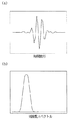
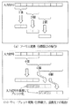
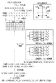
まず、フーリエ変換とウェーブレット変換による変復調の相違点について、図1、図2を用いて説明する。図1(a)はウェーブレットの時間波形の概念説明のためのグラフであり、図1(b)はウェーブレットの周波数スペクトルの概念説明のためのグラフ2(a)は直交変換におけるデータの流れを示す説明図、図2(b)は重複直交変換におけるデータの流れを示す説明図である。
【0047】
フーリエ変換を用いた変復調においては、互いに直交する複数の三角関数に矩形波の窓関数を乗算して各サブキャリアを構成し、その時の周波数特性はSinc関数(Sinx/x関数)となる。一方、ウェーブレット変換を用いた変復調においては、各サブキャリアが互いに直交する複数のウェーブレットによって構成される。ここでいうウェーブレットとは、図1に示すように時間領域でも周波数領域でも局在する波形のことである。
【0048】
また、フーリエ変換は、図2(a)に示すように変換過程において入力信号のサンプル値を重複せずにブロック化する。図2(a)における例では、分割数2の場合における入力信号のブロック化の流れを示している。一方、ウェーブレット変換は図2(b)に示すように各変換過程において入力信号のサンプル値を分割数だけシフトさせた形で重複させてブロック化する。図2(b)における例では、分割数2、重複度2の場合における入力信号のブロック化の流れを示している。両者の比較から1回の変換過程におけるフィルタ長が同じ分割数でも異なることが分かる。すなわち、フーリエ変換は分割数に対して一意的にサブキャリア波形の形状および時間長が決定されるが、ウェーブレット変換においては、入力信号の重複度によって形状および時間長を変化させることができるという自由度がある。
【0049】
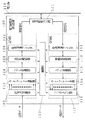
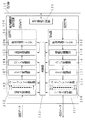
図3は、本発明の実施の形態1による電力線搬送通信装置を示すブロック図である。
【0050】
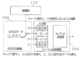
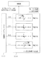
図3において、101は送信部、111は受信部である。送信部101は、信号点写像器102と、ウェーブレット逆変換103と、D/A変換器104と、送信用増幅器105と、帯域通過フィルタ106とを備える。また、受信部111は、帯域通過フィルタ112、増幅度制御器113と、A/D変換器114と、ウェーブレット変換115と、シンボル判定器116とを備える。電力線搬送通信装置100は、送信部101と、受信部111と、電力線結合回路121と、制御部122とから構成される。
【0051】
このように構成された電力線搬送通信装置の動作について、図4と図5を用いて説明する。図4は電力線搬送通信装置の送信部101の動作を説明するための説明図であり、図5は電力線搬送通信装置の受信部111の動作を説明するための説明図である。なお、ウェーブレット変換過程におけるサブキャリア数Nとフィルタ長Mには自由度があり、サブキャリアの数Nは2のべき乗、フィルタ長Mはサブキャリアの数Nの任意の整数倍の値をとることが可能である。しかし、本実施の形態では、説明を簡単にするため、使用周波数帯域を4分割するウェーブレットを使用する。すなわち、通信に使用するサブキャリア数Nを4本として説明する。また、ウェーブレットを構成する各フィルタはサブキャリア数Nの2倍のフィルタ長を有し、2つの信号点データを用いて変換を行うものとする。
【0052】
まず、図4を用いて、送信部101のデータの流れについて説明する。
【0053】
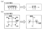
信号点写像器102は、まず、送信するデータ(送信ビット系列)を適当な長さのビット列を複数生成する。例えば、「0001111010110100」というデータを、「00」、「01」、「11」、「10」、「10」、「11」、「01」、「00」のように2ビットずつに分割して各サブキャリアに割り当てるビット列を生成する。次に、信号点写像器102は、この生成した「00」、「01」、「11」、「10」の各ビット列をそれぞれ「+1」、「+3」、「−3」、「−1」といったパルス振幅変調(Pulse Amplitude Modulation、PAM)に相当する信号点に写像する。そして、このPAM信号点データをウェーブレット逆変換103の入力部にT1のように割り当てる。ウェーブレット逆変換103は、T1のように割り当てられた2つの信号点データを用いて、ウェーブレット逆変換を行い、1シンボル期間における時間軸上の送信波形のサンプル値を出力する。D/A変換器104は、この時間サンプル値(時間波形系列データ)を一定のサンプリング時間で出力する。送信用増幅器105は、この送信波形を送信信号レベルまで増幅し、帯域通過フィルタ106は、不要な周波数成分を除去する。電力線結合回路121は、帯域通過フィルタ106によって波形整形された信号を電力線通信用信号として電力線110に出力する。以上が、送信時におけるデータの流れの説明である。
【0054】
次に、図5を用いて受信部111のデータの流れについて説明する。
【0055】
まず、電力線結合回路121は、電力線110から電力線通信用信号を抽出する。帯域通過フィルタ112は、電力線結合回路121によって抽出した信号から帯域外の雑音信号を除去して増幅度制御器113に出力する。増幅度制御器113は、A/D変換器114のダイナミックレンジ内に収まるように信号レベルを調整し、A/D変換器114は、この信号波形を送信側のサンプリング・タイミングと同タイミングでサンプリングしてディジタル化する。ウェーブレット変換115は、この波形データをウェーブレット変換し、サブキャリア毎の信号点データを得る。シンボル判定器116は、この信号点データを逆写像し、最も近いと思われるビット列に復元し、受信データを得る。以上が、受信時におけるデータの流れの説明である。
【0056】
なお、本実施の形態では、送信データを、順番に複数のサブキャリアに割り当てることで高速な通信を可能としているが、同じデータを同時に異なる複数のサブキャリアに割り当てて送信することにより、より信頼性の高いデータ通信も可能になる。
【0057】
上述したような構成により、OFDM伝送方式で必要であったガードインターバルという冗長的な信号部分が必要でなくなり、伝送効率を向上することが可能となる。また、複素演算を必要とするフーリエ変換を実部だけの演算のみで行うウェーブレット変換で実現しているため、演算量を削減することができ、回路規模を低減することができる。
【0058】
(実施の形態2)
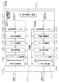
図6は、本発明の実施の形態2による電力線搬送通信装置を示すブロック図である。本実施の形態では、実施の形態1におけるベースバンド信号を任意の搬送波を中心とする帯域信号に拡張する場合について説明する。
【0059】
図6において、101は送信部、111は受信部である。送信部101は、信号点写像器102と、ウェーブレット逆変換103と、送信用周波数変換器としてのSSB(Single Side Band、片側帯域)変調器107と、D/A変換器104と、送信用増幅器105と、帯域通過フィルタ106とを備える。また、受信部111は、帯域通過フィルタ112と、増幅度制御器113と、A/D変換器114と、受信用周波数変換器としてのSSB復調器117と、ウェーブレット変換115と、シンボル判定器116とを備える。電力線搬送通信装置100は、送信部101と、受信部111と、電力線結合回路121と、制御部122とから構成される。
【0060】
このように構成された電力線搬送通信装置の動作について、図4と図5を用いて説明する。なお、本実施の形態では、説明を簡単にするため、使用周波数帯域を4分割するウェーブレットとし、ウェーブレットを構成する各フィルタはサブキャリア数Nの2倍のフィルタ長を有するものとする。また、本実施の形態における動作は、実施の形態1を周波数シフトする以外は同様である。
【0061】
まず、図4を用いて、送信部101のデータの流れについて説明する。信号点写像器102は、まず、送信するデータ(送信ビット系列)を適当な長さのビット列を複数生成する。例えば、「0001111010110100」というデータを、「00」、「01」、「11」、「10」、「10」、「11」、「01」、「00」のように2ビットずつに分割して各サブキャリアに割り当てるビット列を生成する。次に、信号点写像器102は、この生成した「00」、「01」、「11」、「10」の各ビット列をそれぞれ「+1」、「+3」、「−3」、「−1」といったパルス振幅変調(PAM)に相当する信号点に写像する。そして、このPAM信号点データをウェーブレット逆変換103の入力部にT1のように割り当てる。ウェーブレット逆変換103は、T1のように割り当てられた2つの信号点データを用いて、ウェーブレット逆変換を行い、1シンボル期間における時間軸上の送信波形のサンプル値を出力する。SSB変調器107は、この送信サンプル系列を周波数シフトする。D/A変換器104は、周波数シフトされた時間サンプル値を一定のサンプリング時間で出力する。送信用増幅器105は、この送信波形を適当なレベルに増幅し、帯域通過フィルタ106は、不要な周波数成分を除去する。電力線結合回路121は、帯域通過フィルタ106によって波形整形された信号を電力線通信用信号として電力線110に出力する。以上が、送信時におけるデータの流れの説明である。
【0062】
次に、図5を用いて受信部111のデータの流れについて説明する。
【0063】
まず、電力線結合回路121は、電力線110から電力線通信用信号を抽出する。帯域通過フィルタ112は、電力線結合回路121によって抽出した信号から帯域外の雑音信号を除去して増幅度制御器113に出力する。増幅度制御器113は、A/D変換器114のダイナミックレンジ内に収まるように信号レベルを調整し、A/D変換器114は、この信号波形を送信側のサンプリング・タイミングと同タイミングでサンプリングしてディジタル化する。SSB復調器117は、このディジタル信号をベースバンド帯域にダウンコンバートする。ウェーブレット変換115はこの波形データをウェーブレット変換し、サブキャリア毎の信号点データを得る。シンボル判定器116は、この信号点データを逆写像し、最も近いと思われるビット列に復元し、受信データを得る。以上が、受信時におけるデータの流れの説明である。
【0064】
この構成により、本発明における実施の形態1と同様にOFDM伝送方式で必要であったガードインターバルという冗長的な信号部分が必要なくなり、周波数利用効率を向上することが可能となる。また、複素演算を必要とするフーリエ変換を実部だけの演算のみで行うウェーブレット変換で実現しているため、演算量を削減でき、回路規模を低減することができる。さらに、任意の周波数帯へのシフトが可能となるため、例えば宅内と宅外で使用できる周波数帯が各国で異なる場合についても容易に対応することができ、ベースバンド伝送方式のみで対応するよりも回路規模をさらに抑えることが可能となる。
【0065】
(実施の形態3)
図7は、本発明の実施の形態3による電力線搬送通信装置を示すブロック図である。
【0066】
図7において、101は送信部、111は受信部である。送信部101は、信号点写像器102と、ウェーブレット逆変換103と、直交変調器108と、D/A変換器104と、送信用増幅器105と、帯域通過フィルタ106とを備える。また、受信部111は、帯域通過フィルタ112、増幅度制御器113と、A/D変換器114と、直交復調器118と、ウェーブレット変換115と、シンボル判定器116とを備える。電力線搬送通信装置100は、送信部101と、受信部111と、電力線結合回路121と、全体制御部122とから構成される。
【0067】
このように構成された電力線搬送通信装置の動作について、図8と図9を用いて説明する。図8は電力線搬送通信装置の送信部101の動作を説明するための説明図であり、図9は電力線搬送通信装置の受信部111の動作を説明するための説明図である。なお、本実施の形態では、説明を簡単にするため、使用周波数帯域を4分割するウェーブレットを使用し、ウェーブレットを構成する各フィルタはサブキャリア数Nの2倍のフィルタ長を有するものとする。
【0068】
まず、図8を用いて、送信部101のデータの流れについて説明する。
【0069】
信号点写像器102は、まず、送信するデータ(送信ビット系列)を適当な長さのビット列を複数生成する。例えば、「0001111010110100」というデータを、「00」、「01」、「11」、「10」、「10」、「11」、「01」、「00」のように2ビットずつに分割して各サブキャリアに割り当てるビット列を生成する。次に、信号点写像器102は、この生成した「00」、「01」、「11」、「10」の各ビット列を直交振幅変調(Quardrature Amplitude Modulation、QAM)に対応する複素領域の信号点に写像する。そして、このQAM信号点データをウェーブレット逆変換103の入力部にT2のように割り当てる。このとき、複素信号点データを実部と虚部に分けて割り当てる。ウェーブレット逆変換103は、T2のように割り当てられた2つの信号点データによって、実部、虚部それぞれに対してウェーブレット逆変換を行い、1シンボル期間における時間軸上の送信波形のサンプル値を出力する。このとき、送信波形のサンプル値は複素数のままである。直交変調器108は、この複素信号を直交変調することにより、任意の搬送波帯域に周波数シフトする。D/A変換器104は、周波数シフトした時間サンプル値を一定のサンプリング時間で出力する。送信用増幅器105は、この送信波形を適当なレベルに増幅し、帯域通過フィルタ106は、不要な周波数成分を除去する。電力線結合回路121は、帯域通過フィルタ106によって波形整形された信号を電力線通信用信号として電力線110に出力する。以上が、送信時におけるデータの流れの説明である。
【0070】
次に、図9を用いて受信部111のデータの流れについて説明する。
【0071】
まず、電力線結合回路121は、電力線110から電力線通信用信号を抽出する。帯域通過フィルタ112は、電力線結合回路121によって抽出した信号から帯域外の雑音信号を除去して増幅度制御器113に出力する。増幅度制御器113は、A/D変換器114のダイナミックレンジ内に収まるように信号レベルを調整し、A/D変換器114は、この信号波形を送信側のサンプリング・タイミングと同タイミングでサンプリングしてディジタル化する。直交復調器118は、波形データをベースバンド帯域にダウンコンバートし、複素ベースバンド信号に変換する。ウェーブレット変換115はこの複素波形データをウェーブレット変換し、サブキャリア毎の複素信号点データを得る。シンボル判定器116は、この信号点データを逆写像し、最も近いと思われるビット列に復元し、受信データを得る。以上が、受信時におけるデータの流れの説明である。
【0072】
この構成により、OFDM伝送方式で必要であったガードインターバルという冗長的な信号部分が必要でなくなり、周波数利用効率を向上することが可能となる。また、直交変復調により複素領域の信号点データを使用できるため、さらに周波数利用効率が向上する。
【0073】
(実施の形態4)
本発明の実施の形態4による電力線搬送通信装置の構成は、図3、図6または図7に示す構成である。本実施の形態では、ウェーブレット逆変換103およびウェーブレット変換115を一般化重複直交変換(Generized Lapped orthogonal Transform、GLT)によって構成する場合について説明する。GLTは重複直交変換(Lapped Orthogonal Transform、LOT)の構成をフィルタのタップ数に関して一般化したものである。
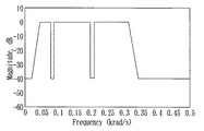
【0074】
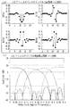
図10(a)は4分割の完全再構成のGLTを実現するフィルタバンク回路の各フィルタのインパルス応答の例を示すグラフであり、図10(b)は4分割の完全再構成のGLTを実現するフィルタバンク回路の各フィルタの周波数応答の例を示すグラフである。
【0075】
なお、本実施の形態では、GLTを実現するフィルタバンク回路をFIRフィルタ群で構成したが、ポリフェーズフィルタやラティス構造によっても構成可能である。また、完全再構成のGLTを実現するフィルタバンク回路の例を示したが、疑似完全再構成のフィルタバンク回路も適用可能である。疑似完全再構成とすることにより、完全再構成の場合よりもさらに、各サブキャリアにおけるサイドローブを小さくすることが可能となる。
【0076】
図10のようなフィルタバンク回路を構成することにより、ウェーブレット変換を実現するフィルタバンク回路の全フィルタに対して直線位相特性を持たすことが可能となる。全てのフィルタが直線位相特性をもつので、フィルタバンクに必要な乗算器の個数を半分にすることができ、回路規模を小さくすることができる。また、各サブキャリアの周波数特性をメインローブを中心に急峻に設計できるため、受信時において、他のサブキャリアからの干渉や帯域外の雑音による影響を低減することが可能となる。
【0077】
(実施の形態5)
本発明の実施の形態5による電力線搬送通信装置の構成は、図3、図6または図7に示す構成である。本実施の形態では、ウェーブレット逆変換103およびウェーブレット変換115を拡張変調重複直交変換(Extended modulated Lapped Transform、ELT)によって構成する場合について説明する。ELTはMLT(Modulated Lapped Transform)の構成をフィルタのタップ数に関して一般化したものである。
【0078】
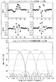
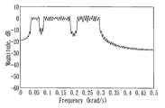
図11(a)は4分割のELTを実現するフィルタバンク回路の各フィルタのインパルス応答の例を示すグラフであり、図11(b)は4分割のELTを実現するフィルタバンク回路の各フィルタの周波数応答の例を示すグラフである。
【0079】
なお、本実施の形態では、ELTを実現するフィルタバンク回路をFIRフィルタ群で構成したが、ポリフェーズフィルタやラティス構造によっても構成可能である。
【0080】
図11のようなフィルタ係数をもつフィルタバンク回路を構成することにより、実施の形態4に記載のLOTあるいはGLTよりも、さらに各サブキャリアのサイドローブを低減することが可能となる。各サブキャリアの周波数特性をメインローブを中心に急峻に設計できるため、電力線搬送通信装置100において既存システムに影響を与えないようにする目的で従来方式では必要となる帯域阻止フィルタを必要とせず、受信時において他のサブキャリアからの干渉や帯域外の雑音による影響を低減することが可能となる。
【0081】
(実施の形態6)
本発明の実施の形態6では、図3、図6、図7の電力線搬送通信装置100を構成するウェーブレット逆変換103およびウェーブレット変換115をポリフェーズフィルタによって構成する場合について、図12、図13を用いて説明する。図12(a)は一般的なFIRフィルタで構成した帯域合成フィルタバンク回路を示すブロック図であり、図12(b)は一般的なFIRフィルタで構成した帯域分割フィルタバンク回路を示すブロック図、図13(a)はポリフェーズフィルタで構成した帯域合成フィルタバンク回路を示すブロック図、図13(b)はポリフェーズフィルタで構成した帯域分割フィルタバンク回路を示すブロック図である。
【0082】
まず、一般的なFIRフィルタで構成したフィルタバンク回路の構成について、図12を用いて説明する。図12において、201は信号のサンプリング・レートをN倍にするアップサンプラ、202はFIRフィルタ、203は互いに直交する複数のFIRフィルタ202を組み合わせたFIRフィルタ群、204は2入力加算器である。以上より、ウェーブレット逆変換103としての帯域合成フィルタバンク回路200が構成される。
【0083】
また、211はFIRフィルタ、212は互いに直交する複数のFIRフィルタ211を組み合わせたFIRフィルタ群、213はサンプリング・レートを1/Nにするダウンサンプラである。以上により、ウェーブレット変換115としての帯域分割フィルタバンク回路210が構成される。
【0084】
なお、ウェーブレット逆変換103のFIRフィルタ群203とウェーブレット変換器210のFIRフィルタ群212とを構成する各FIRフィルタ202、211は、ウェーブレット変換115に対する入力信号とウェーブレット変換115の出力信号とが遅延を除いて一致するように構成されている。例えば、この条件を満たすフィルタ係数としては、(表1)、(表2)が挙げられる。
【0085】
【表1】

【表2】
(表1)、(表2)に示したフィルタ係数は帯域を4分割するフィルタバンク回路の一例である。ここで、hは一般的なFIRフィルタを示す。このFIRフィルタは、入力データを遅延する縦続接続の7個の遅延素子と、この遅延素子の出力データおよび上記入力データに係数を乗算する8個の乗算器と、この乗算器の出力データを入力側から順次に加算して累積値を得る7個の加算器とから成る。tapは上記乗算器を示し、αは上記乗算器の係数を示す。またαMNのMはフィルタ番号、Nはタップ番号を示す。
【0088】
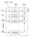
次に、ポリフェーズフィルタで構成したフィルタバンク回路について、図13を用いて説明する。図13において、301はポリフェーズフィルタ、302は信号のサンプリング・レートをN倍にするアップサンプラ、303は2入力加算器、304は1サンプリング分遅延させる遅延素子(レジスタ)である。以上より、ウェーブレット逆変換103としての帯域合成フィルタバンク回路300が構成される。
【0089】
また、311は1サンプリング分遅延させる遅延素子、312はサンプリング・レートを1/Nにするダウンサンプラ、313はポリフェーズフィルタである。以上により、ウェーブレット変換115としての帯域分割フィルタバンク回路310が構成される。
【0090】
図14は、図13のポリフェーズフィルタ301、313を示すブロック図である。図14において、321はフィルタ、322は2入力加算器である。なお、ポリフェーズフィルタ301とポリフェーズフィルタ313とを構成する各フィルタは、帯域合成フィルタバンク回路300に対する入力信号と帯域分割フィルタバンク回路310の出力信号とが遅延を除いて一致するように構成されている。例えば、(表1)、(表2)とのフィルタ係数による演算結果と同一にするためには各ポリフェーズフィルタを(表3)〜(表10)のように構成すればよい。
【0091】
【表3】
【表4】
【表5】
【表6】
【表7】
【表8】
【表9】
【表10】
図12のフィルタバンク回路と図13のフィルタバンク回路との間の相違点は、サンプリング・レートを変更する箇所が異なる点である。帯域合成フィルタバンク回路200、300において、図12では、フィルタに入力する前に信号をアップサンプリングするが、図13では、フィルタ演算の後にアップサンプリングする。一方、帯域分割フィルタバンク回路210、310においては、図12では、フィルタ演算の後にダウンサンプリングして、図13では、フィルタ演算の前にダウンサンプリングする。つまり、図13におけるフィルタ演算は図12よりも遅い速度で実行できる。
【0100】
なおこの実施の形態では、帯域合成フィルタバンクのフィルタ出力のタイミング制御部をアップサンプラ302、2入力加算器303、遅延素子304を用いて構成したが、マルチプレクサによっても構成可能である。
【0101】
したがって、この構成により、変調と復調時における重複直交変換の際の演算を低レートで実行することが可能となる。すなわち、動作クロック周波数を低くできるため回路の消費電力を低減することができる。また、このことは単位時間当たりの演算量が低減されるという観点から見ると、演算器を流用することが可能となり、回路規模を小さくすることも可能となる。
【0102】
(実施の形態7)
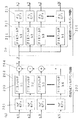
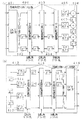
図15(a)は図3、図6、図7の電力線搬送通信装置100のウェーブレット逆変換103としての帯域合成フィルタバンク回路を示すブロック図であり、図15(b)は図3、図6、図7の電力線搬送通信装置100のウェーブレット変換115としての帯域分割フィルタバンク回路を示すブロック図であり、フィルタバンク回路として、ラティス構造のELTフィルタバンク回路を示す。すなわち、本実施の形態では、ウェーブレット逆変換103およびウェーブレット変換115をラティス構造のフィルタバンク回路によって構成する場合について説明する。
【0103】
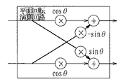
図15において、401はタイプIVの離散コサイン変換(DiscreteCosine Transform、DCT)器、402は1サンプリング分遅延させる遅延素子、403は平面回転演算器、404は2サンプリング分遅延させる遅延素子、405は信号のサンプリング・レートをN倍にするアップサンプラ、406は2入力加算器、407は1サンプリング分遅延させる遅延素子である。以上より、帯域合成フィルタバンク回路400が構成される。一方、411は1サンプリング分遅延させる遅延素子、412はサンプリング・レートを1/Nにするダウンサンプラ、413は2サンプリング分遅延させる遅延素子、414は平面回転演算器、415は1サンプリング分遅延させる遅延素子、416はタイプIVの離散コサイン変換器である。以上より、帯域分割フィルタバンク回路410が構成される。なお、平面回転演算器403と414は、図16に示す平面回転演算回路を複数組み合わせて構成したものである。図16は平面回転演算回路を示す機能ブロック図である。
【0104】
この構成により、実施の形態6で説明したポリフェーズフィルタで構成した場合と同様に、変調と復調時における重複直交変換の際の演算レートを低減することが可能となる。さらに、高速DCTなどを併用することによって演算量も低減できるため、回路の消費電力および回路規模を低減することができる。
【0105】
(実施の形態8)
本発明の実施の形態8では、図3、図6、図7の電力線搬送通信装置100のウェーブレット逆変換103と図3、図6、図7の電力線搬送通信装置100のウェーブレット変換115において、重複係数に応じたフィルタ係数を複数パターン用意しておき、そのフィルタ係数を変更する方法について説明する。
【0106】
まず、送信部101のウェーブレット逆変換103と受信部111のウェーブレット変換115に対して、重複係数に応じたフィルタ長の異なるフィルタ係数を複数パターン用意しておく。そして、送信部101および受信部111の各制御部122よりウェーブレット逆変換103およびウェーブレット変換115に対して、フィルタのパターン番号を指定することにより、パターン番号に合わせてフィルタバンク回路内のフィルタ係数を変化させる。この時、フィルタのパターン番号は制御信号などを使用して送信側および受信側で一致させる必要がある。また、フィルタ係数を変更する基準としては、送信部101から送信される電力線通信信号や、伝送路の変動、受信レベル等が考えられる。例えば、S/N(信号電力対雑音電力比)を用いる場合、受信時においてS/Nが大きい場合は、各サブキャリアから見て帯域外の雑音が小さいため、フィルタ長の短いフィルタによって復調動作を行い、S/Nが小さい場合は、他の帯域からの雑音の影響を受けにくくするため、フィルタ長の大きいフィルタ係数を使用する。
【0107】
この制御により、伝送路の雑音状態が良好な場合の演算量を低減することができ、受信時の消費電力を削減することが可能となる。また、雑音状態が劣悪な場合においても、安定した受信を行うことが可能となる。
【0108】
(実施の形態9)
本発明の実施の形態9では、図3、図6、図7のウェーブレット逆変換103とウェーブレット変換115とをラティス構造で構成した場合において、重複係数に応じた平面回転角パラメータを複数パターン用意しておき、その平面回転角パラメータを変更する方法について説明する。
【0109】
まず、送信部101のウェーブレット逆変換103と受信部111のウェーブレット変換115は実施の形態7のようにラティス構造で構成する。そして、送信部101のウェーブレット逆変換103と受信部111のウェーブレット変換115に対して、重複係数に応じた平面回転角パラメータを複数パターン用意しておく。そして、送信部101および受信部111の各制御部122よりウェーブレット逆変換103とウェーブレット変換115に対して、平面回転角パラメータのパターン番号を指定することにより、そのパターン番号に合わせてフィルタバンク回路内の平面回転角パラメータを変化させる。この時、平面回転角パラメータのパターン番号は制御信号などを使用して送信機および受信機で一致させる必要がある。また、平面回転角パラメータを変更する基準としては、送信部101から送信される電力線通信信号や、伝送路の変動、受信レベル等が考えられる。例えば、S/Nを用いる場合、受信時においてS/Nが大きい場合は、各サブキャリアから見て帯域外の雑音が小さいため、重複係数が小さい平面回転角パラメータによって復調動作を行い、S/Nが小さい場合は、他の帯域からの雑音の影響を受けにくくするため、重複係数が大きい平面回転角パラメータを使用する。
【0110】
この制御により、伝送路のノイズ環境が良好な場合の演算量を低減することができ、受信時の消費電力を削減することが可能となる。また、雑音状態が劣悪な場合においても、安定した受信が行うことが可能となる。さらに、実施の形態8のようにフィルタ係数を複数パターン用意するのに比べ、記憶容量を減らすことができる。
【0111】
(実施の形態10)
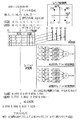
図17は、本発明の実施の形態10による電力線搬送通信装置の制御方法(すなわち図3、図6または図7の制御部122の動作)を説明するための説明図であり、本実施の形態では、特定のサブキャリアのみを出力する場合について説明する。なお、説明を簡単にするため、サブキャリア数を4本としている。
【0112】
図17において、102は信号点写像、103はウェーブレット逆変換、122は制御部である。
【0113】
まず、信号点写像器102において、「+1」、「+3」、「−3」、「−1」、「+1」、「+3」、「−3」、「−1」の順で信号点写像されたデータが出力されたとする。このとき、制御部122が信号点写像器102に対して、使用しないサブキャリア番号を指定することにより、指定した番号のサブキャリア部分に対してデータを入力しないようにする。すなわち、ゼロを挿入する。例えば、1番目と4番目のサブキャリアを出力しないようにする場合は、1番目と4番目のサブキャリアを出力するフィルタの入力部分にはゼロを挿入して、写像された信号点データは2番目と3番目のサブキャリアの入力部分に入れる。そして、ウェーブレット逆変換103は、各々の入力データに基づきウェーブレット逆変換を行う。
【0114】
このように制御することにより、出力するサブキャリアを容易に選択することができ、特定の周波数にのみ信号を出力することが可能になる。つまり、国別の法規制によって各国毎に使用可能な周波数帯が異なる場合であっても、容易に対応することが可能となる。
【0115】
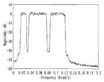
さらに、本実施の形態による電力線搬送通信装置の有効性を、図18、図19、図20を用いて分かりやすく説明する。図18は電力線搬送通信に認可された周波数スペクトルの例を示すグラフであり、図19はOFDM伝送を用いた場合の送信周波数スペクトルを示すグラフ、図20は電力線搬送通信装置の送信周波数スペクトルを示すグラフである。
【0116】
例えば、ある国の法規制による周波数割り当てが図18に示すようであったとする。従来のOFDMを用いた電力線通信搬送装置による送信信号は図19に示すようになり、図18の規制を満足するためには、別途帯域阻止フィルタが必要となる。すなわち、国毎に異なる帯域阻止フィルタのフィルタ係数を用意しておく必要がある。一方、本実施の形態による電力線搬送通信装置は、本実施の形態における動作のみで図20に示すような送信信号スペクトラムを得ることができるので、帯域阻止フィルタを必要としない。このことから、本実施の形態による電力線搬送通信装置は、各国で異なる法規制に柔軟に対応することができる。
【0117】
(実施の形態11)
図21は、図3、図6、図7の電力線搬送通信装置の制御方法(すなわち本発明の実施の形態11による電力線搬送通信装置の制御部122の動作)を説明するための説明図である。本実施の形態では、電力線上のノイズレベルを検出する方法について説明する。
【0118】
図21において、115はウェーブレット変換、116はシンボル判定器、122は制御部である。
【0119】
次に、電力線上のノイズレベル検出動作について説明する。
【0120】
まず、ウェーブレット変換115は、電力線110上のノイズの周波数分布を検知するために、サブキャリア毎の信号点データに復調する。次に、シンボル判定器116は、サブキャリア毎の信号点データに基づき、どの信号点付近に存在するノイズ成分が大きいかを測定する。このとき、雑音が全くない場合には、各サブキャリアにおける信号点データはすべて0になる。したがって、このデータの値が0からどれだけずれたかによってノイズ量を推定する。そして、シンボル判定器116は、所望値よりもノイズが大きなサブキャリアを判定して、そのサブキャリア番号を制御部122に対して通知し、そのサブキャリアを制御部122は使用できないようにする。
【0121】
なお、本実施の形態では、電力線上に信号を重畳しない状態でのノイズレベル検出方法について説明したが、送受信間で既知の信号を使用しても同様な方法で実現することができる。すなわち、通信状態においてもノイズ検出を行える。
【0122】
このような制御を行うことにより、電力線上のノイズ状態を把握することができ、使用可能なサブキャリアを選択することができる。制御部122において、あらかじめ大きなノイズ成分が存在する周波数位置を避けるようにサブキャリアを選定することにより、より信頼性の高い通信が可能となる。
【0123】
(実施の形態12)
本発明の実施の形態12による電力線搬送通信装置における制御方法として、伝送速度を指定する速度に変更する制御方法について、図3と図4を用いて説明する。
【0124】
まず、制御部122は、外部から指定された伝送速度を実現するために必要な信号点の個数やサブキャリアの数を算出し、その算出結果と実施の形態11による使用可能サブキャリアの判定結果に基づき、サブキャリアの選択を行う。次に、制御部122は、信号点写像器102に対して、使用するサブキャリア番号と信号点の個数とを指定する。信号点写像器102は、その設定値に従って信号点写像、サブキャリアへのデータ配置処理を対応させる。
【0125】
例えば、外部から必要な伝送速度が指定され、制御部122において指定された伝送速度に合うように算出された結果が、キャリア数2、信号点の個数が4であるとする。また、実施の形態11による判定で、使用できるサブキャリアが2番目のサブキャリア以外の3本であるとする。このとき、制御部122は、例えば、1番目と3番目のサブキャリアを選択することができる。また、他の使用しないサブキャリア(この例では4番目のキャリア)は、別の通信に利用することができる。
【0126】
このように制御することにより、伝送速度を指定する速度に容易に変更することができ、また、指定された伝送速度を実現する以外のサブキャリアを別の通信に利用することができるため、帯域の利用効率を向上することが可能となる。
【0127】
(実施の形態13)
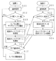
図22は、本発明の実施の形態13による電力線搬送通信装置の制御部122の動作を示すフローチャートである。本実施の形態では、通常の通信中に受信データにエラーが発生した場合、送信する周波数位置をずらし、ノイズの影響を回避しながら、電力線搬送通信装置1(例えば自装置)と電力線搬送通信装置2(例えば相手装置)の間の通信手順を合わせる方法について説明する。なお、電力線搬送通信装置1と電力線搬送通信装置2の構成は図3の構成とする。
【0128】
図22において、最初の状態(S11、S21)では、電力線搬送通信装置1と電力線搬送通信装置2の間の通信はキャリアパターン1で通信している。そして、電力線搬送通信装置1で、エラー数があるしきい値以上になった場合(S12)には、エラー数があるしきい値を越えているサブキャリアを検知し(S13)、変更するサブキャリアの番号あるいは位置を仮に設定する(S14)。なお、このとき変更したキャリアパターンをキャリアパターン2とする。その後、設定したキャリアパターン2の内容を、現在の通信に利用しているキャリアパターン1で電力線搬送通信装置2へ送信する(S15)。その後、電力線搬送通信装置1は、自分のキャリアパターンをキャリアパターン2に変更する。なお、キャリアパターンは1つのサブキャリアまたは複数のサブキャリアの組からなるものである。
【0129】
キャリアパターン1でキャリアパターン2の内容を受信した電力線搬送通信装置2では、キャリアパターン変更であるか否かの判別を行い(S22)、変更でなければ通常処理(S21)に戻り、変更であれば受信部111で重複直交変換をかける周波数位置をキャリアパターン2に変更し(S23)、さらにキャリアパターンを変更したことをキャリアパターン2で変調して電力線搬送通信装置1へ返送する(S24)。
【0130】
電力線搬送通信装置1では、この完了通知の内容が正しく送られたことを判別する(S16)。そこで、変更完了通知を正しく受け取れた場合には通常処理(S11)へ移るが、変更完了通知を受け取れなかった場合には、S/Nのしきい値を変更して(S17)、再度キャリアパターンの選定処理(S13)に移る。そして、再度キャリアパターンの変更のシーケンスを行う。この一連のシーケンスをエラー数が少なくなるまで繰り返す。
【0131】
ここで、上記シーケンスは、通常の通信時のみではなく、初期のインストール時の設定としても利用できる。
【0132】
なお、本実施の形態では、使用するサブキャリアを変更することにより、受信エラー数を減少させたが、信号点写像器の信号点配置を変更することによってエラー数を減少さることも可能である。例えば、図23に示すように、4値の信号点配置から2つの配置方法へ変更しても良く、通信上の整合性は本実施の形態におけるシーケンスと同様の手段で実現することができる。ここで、図23(a)、(b)は電力線搬送通信装置の信号点写像器102の信号点数の変化を示す説明図である。
【0133】
このように本実施の形態によれば、誤り率の小さいサブキャリアから優先的に通信に使用するようにしたので、受信エラー数を減少させることができる。
【0134】
(実施の形態14)
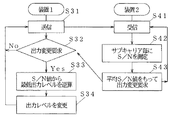
図24は、本発明の実施の形態14による電力線搬送通信装置の動作を示すフローチャートであり、電力線搬送通信装置2(例えば相手装置)の受信結果に基づき、電力線搬送通信装置1(例えば自装置)の送信出力レベルを変更する動作を示す。なお、電力線搬送通信装置1と電力線搬送通信装置2の構成は図3の構成である。
【0135】
図24において、初期状態(S31)では、電力線搬送通信装置1はある出力レベルで送信している。電力線搬送通信装置2では、電力線搬送通信装置1の信号を受信して(S41)、サブキャリア毎にS/Nを測定する(S42)。次に平均S/N値に基づいて電力線搬送通信装置1に出力レベルの変更要求を行う(S43)。
【0136】
このS/N値と変更要求とを受け取った電力線搬送通信装置1では、変更要求の有無を判別し(S32)、このS/N値から逆算して(S33)出力レベルを決定(S34)し、そのレベルで電力線搬送通信装置2に再度送信する。
【0137】
この動作により、電力線上のノイズレベルが低く、通信エラーが発生しない場合には、出力レベルを低下させることにより、送信に必要な電力を削減することが可能になる。
【0138】
このように本実施の形態によれば、電力線上のノイズレベルが低く通信エラーが発生しない場合には出力レベルを低下させることができるので、送信に必要な電力を削減することができる。
【0139】
【発明の効果】
以上説明したように本発明の請求項1に記載の電力線搬送通信装置によれば、送信部と、受信部と、前記送信部からの信号を電力線に対して電力線通信用信号として重畳すると共に電力線から電力線通信用信号のみを抽出する電力線結合回路と、前記送信部と前記受信部の各構成要素を制御する制御部とを有し、複数のサブキャリアを用いて通信を行う電力線搬送通信装置であって、前記送信部は、入力される送信データから複数のビット列を生成して前記ビット列を各サブキャリアの信号点に写像する信号点写像器と、前記信号点写像器により写像された各サブキャリアの信号点データに基づき互いに直交したウェーブレット波形をもって各サブキャリアの変調を行うことにより時間波形系列データの生成を行うウェーブレット逆変換器と、前記ウェーブレット逆変換器による時間波形系列データをアナログ変換するD/A変換器とを有し、前記受信部は、前記電力線結合回路により電力線から抽出された電力線通信用信号をディジタル変換してサンプリング系列波形データを得るA/D変換器と、前記A/D変換器によるサンプリング系列波形データを各サブキャリアの信号点データに変換するウェーブレット変換器と、前記ウェーブレット変換器から出力される複数の信号点データを逆写像して前記信号点写像器で写像されたビット列を判別し受信データ系列として合成するシンボル判定器とを有し、前記ウェーブレット逆変換器と前記ウェーブレット変換器は、重複係数に応じたフィルタ長の異なる複数のフィルタ係数パターンを有し、送信部から送信される電力線通信信号や、伝送路の変動、受信レベル等の受信条件に応じて、前記複数のフィルタ係数パターンの中から適切なフィルタ係数パターンを選択することを特徴とする電力線搬送通信装置とすることにより、OFDM伝送方式で必要であったガードインターバルという冗長な信号部分が必要でなくなり、周波数利用効率を向上することができ、また、複素演算を必要とするフーリエ変換を実部の演算のみで行うウェーブレット変換で実現しているので、演算量を削減することができ、回路規模を低減することができるという作用を有する。また、伝送速度劣化の要因となるガードインターバルを排除しても通信が可能であり、各国の電波法規制に応じて通信に利用する周波数帯域を限定し、回路規模増大の要因となる帯域阻止フィルタを設置することなしに既存システムの使用帯域において十分な減衰量を得ることができるという作用を有する。さらに、伝送路の雑音状態が良好な場合の演算量を低減することができ、受信時の消費電力を削減することができ、また、雑音状態が劣悪な場合においても安定した受信を行うことができるという有利な効果が得られる。
【0140】
請求項2に記載の電力線搬送通信装置によれば、送信部と、受信部と、前記送信部からの信号を電力線に対して電力線通信用信号として重畳すると共に電力線から電力線通信用信号のみを抽出する電力線結合回路と、前記送信部と前記受信部の各構成要素を制御する制御部とを有し、複数のサブキャリアを用いて通信を行う電力線搬送通信装置であって、前記送信部は、入力される送信データから複数のビット列を生成して前記ビット列を各サブキャリアの信号点に写像する信号点写像器と、前記信号点写像器により写像された各サブキャリアの信号点データに基づき互いに直交したウェーブレット波形をもって各サブキャリアの変調を行うことにより時間波形系列データの生成を行うウェーブレット逆変換器と、前記ウェーブレット逆変換器から出力される時間波形系列データを任意の搬送波周波数帯域に周波数シフトする送信用周波数変換器と、前記送信用周波数変換器から出力される時間波形系列データをアナログ変換するD/A変換器とを有し、前記受信部は、前記電力線結合回路により電力線から抽出された電力線通信用信号をディジタル変換してサンプリング系列波形データを得るA/D変換器と、前記A/D変換器によるサンプリング系列波形データをベースバンド帯域へ周波数シフトしてベースバンド信号系列を得る受信用周波数変換器と、前記受信用周波数変換器から出力されたベースバンド信号系列を各サブキャリアの信号点データに変換するウェーブレット変換器と、前記ウェーブレット変換器から出力される複数の信号点データを逆写像して前記信号点写像器で写像されたビット列を判別し受信データ系列として合成するシンボル判定器とを有し、前記ウェーブレット逆変換器と前記ウェーブレット変換器は、重複係数に応じたフィルタ長の異なる複数のフィルタ係数パターンを有し、送信部から送信される電力線通信信号や、伝送路の変動、受信レベル等の受信条件に応じて、前記複数のフィルタ係数パターンの中から適切なフィルタ係数パターンを選択することを特徴とする電力線搬送通信装置とすることにより、OFDM伝送方式で必要であったガードインターバルという冗長な信号部分が必要でなくなり、周波数利用効率を向上することができ、また、複素演算を必要とするフーリエ変換を実部の演算のみで行うウェーブレット変換で実現しているので、演算量を削減することができ、回路規模を低減することができるという作用を有する。また、伝送速度劣化の要因となるガードインターバルを排除しても通信が可能であり、各国の電波法規制に応じて通信に利用する周波数帯域を限定し、回路規模増大の要因となる帯域阻止フィルタを設置することなしに既存システムの使用帯域において十分な減衰量を得ることができるという作用を有する。さらに、任意の周波数帯へのシフトが可能になるので、例えば宅内と宅外で使用できる周波数帯が各国で異なる場合についても容易に対応することができ、ベースバンド伝送方式のみで対応するよりも、回路規模をさらに抑えることができるという作用を有する。さらに、伝送路の雑音状態が良好な場合の演算量を低減することができ、受信時の消費電力を削減することができ、また、雑音状態が劣悪な場合においても安定した受信を行うことができるという有利な効果が得られる。
【0141】
請求項3に記載の電力線搬送通信装置によれば、送信部と、受信部と、前記送信部からの信号を電力線に対して電力線通信用信号として重畳すると共に電力線から電力線通信用信号のみを抽出する電力線結合回路と、前記送信部と前記受信部の各構成要素を制御する制御部とを有し、複数のサブキャリアを用いて通信を行う電力線搬送通信装置であって、前記送信部は、入力される送信データから複数のビット列を生成して前記ビット列を各サブキャリアの複素信号点に写像する信号点写像器と、前記信号点写像器により写像された各サブキャリアの複素信号点データに基づき互いに直交したウェーブレット波形をもって各サブキャリアの変調を行うことにより複素時間波形系列データの生成を行うウェーブレット逆変換器と、前記ウェーブレット逆変換器から出力される複素時間波形系列データを直交変調することにより任意の搬送波周波数帯域に周波数シフトする直交変調器と、前記直交変調器から出力される複素時間波形系列データをアナログ変換するD/A変換器とを有し、前記受信部は、前記電力線結合回路により電力線から抽出された電力線通信用信号をディジタル変換してサンプリング系列波形データを得るA/D変換器と、前記A/D変換器によるサンプリング系列波形データをベースバンド帯域へ周波数シフトしてベースバンド信号系列を得る直交復調器と、前記直交復調器から出力されたベースバンド信号系列を各サブキャリアの信号点データに変換するウェーブレット変換器と、前記ウェーブレット変換器から出力される複数の信号点データを逆写像して前記信号点写像器で写像されたビット列を判別し受信データ系列として合成するシンボル判定器とを有し、前記ウェーブレット逆変換器と前記ウェーブレット変換器は、重複係数に応じたフィルタ長の異なる複数のフィルタ係数パターンを有し、送信部から送信される電力線通信信号や、伝送路の変動、受信レベル等の受信条件に応じて、前記複数のフィルタ係数パターンの中から適切なフィルタ係数パターンを選択することを特徴とする電力線搬送通信装置とすることにより、OFDM伝送方式で必要であったガードインターバルという冗長な信号部分が必要でなくなり、周波数利用効率を向上することができ、また、複素演算を必要とするフーリエ変換を実部の演算のみで行うウェーブレット変換で実現しているので、演算量を削減することができ、回路規模を低減することができるという作用を有する。また、伝送速度劣化の要因となるガードインターバルを排除しても通信が可能であり、各国の電波法規制に応じて通信に利用する周波数帯域を限定し、回路規模増大の要因となる帯域阻止フィルタを設置することなしに既存システムの使用帯域において十分な減衰量を得ることができるという作用を有する。さらに、直交変復調により複素領域の信号点データを使用できるので、さらに周波数利用効率を向上させることができるという作用を有する。さらに、伝送路の雑音状態が良好な場合の演算量を低減することができ、受信時の消費電力を削減することができ、また、雑音状態が劣悪な場合においても安定した受信を行うことができるという有利な効果が得られる。
【0142】
請求項4に記載の電力線搬送通信装置によれば、請求項1乃至3のいずれか1に記載の電力線搬送通信装置において、ウェーブレット逆変換器とウェーブレット変換器は、完全再構成あるいは疑似完全再構成の重複直交変換機能または一般化重複直交変換機能を有することにより、ウェーブレット変換を実現するフィルタバンク回路の全フィルタに対して直線位相特性を持たすことができるので、フィルタバンクに必要な乗算器の個数を半分にすることができ、回路規模を小さくすることができるという有利な効果が得られる。また、各サブキャリアの周波数特性をメインローブを中心に急峻に設計できるので、受信時において他のサブキャリアからの干渉や帯域外の雑音による影響を低減することができるという有利な効果が得られる。
【0143】
請求項5に記載の電力線搬送通信装置によれば、請求項1乃至3のいずれか1に記載の電力線搬送通信装置において、ウェーブレット逆変換器とウェーブレット変換器は、変調重複変換機能または拡張変調重複変換機能を有することにより、各サブキャリアの再度ろ周波数特性をメインローブを中心に更に急峻に設計できるので、電力線搬送通信装置において既存システムに影響を与えないようにする目的で従来は必要であった帯域阻止フィルタを必要とせず、受信時において他のサブキャリアからの干渉や帯域外の雑音による影響を低減することができるという有利な効果が得られる。
【0144】
請求項6に記載の電力線搬送通信装置によれば、請求項1乃至5のいずれか1に記載の電力線搬送通信装置において、ウェーブレット逆変換器とウェーブレット変換器は、ポリフェーズフィルタバンク回路によって構成することにより、変調時と復調時における重複直交変換の際の演算を低レートで実行することができ、動作クロック周波数を低くすることができるので、回路の消費電力を低減することができるという有利な効果が得られる。また、動作クロック周波数を低くすることができることにより、演算器を流用することができ、回路規模を小さくすることができるという有利な効果が得られる。
【0145】
請求項7に記載の電力線搬送通信装置によれば、送信部と、受信部と、前記送信部からの信号を電力線に対して電力線通信用信号として重畳すると共に電力線から電力線通信用信号のみを抽出する電力線結合回路と、前記送信部と前記受信部の各構成要素を制御する制御部とを有し、複数のサブキャリアを用いて通信を行う電力線搬送通信装置であって、前記送信部は、入力される送信データから複数のビット列を生成して前記ビット列を各サブキャリアの信号点に写像する信号点写像器と、前記信号点写像器により写像された各サブキャリアの信号点データに基づき互いに直交したウェーブレット波形をもって各サブキャリアの変調を行うことにより時間波形系列データの生成を行うウェーブレット逆変換器と、前記ウェーブレット逆変換器による時間波形系列データをアナログ変換するD/A変換器とを有し、前記受信部は、前記電力線結合回路により電力線から抽出された電力線通信用信号をディジタル変換してサンプリング系列波形データを得るA/D変換器と、前記A/D変換器によるサンプリング系列波形データを各サブキャリアの信号点データに変換するウェーブレット変換器と、前記ウェーブレット変換器から出力される複数の信号点データを逆写像して前記信号点写像器で写像されたビット列を判別し受信データ系列として合成するシンボル判定器とを有し、前記ウェーブレット逆変換器と前記ウェーブレット変換器は、ラティス構造のフィルタバンク回路によって構成され、前記ウェーブレット逆変換器と前記ウェーブレット変換器は、更に、重複係数に応じた複数の平面回転角パターンを有し、送信部から送信される電力線通信信号や、伝送路の変動、受信レベル等の受信条件に応じて、前記複数の平面回転角パラメータの中から適切な平面回転角パラメータを選択することを特徴とする電力線搬送通信装置とすることにより、OFDM伝送方式で必要であったガードインターバルという冗長な信号部分が必要でなくなり、周波数利用効率を向上することができ、また、複素演算を必要とするフーリエ変換を実部の演算のみで行うウェーブレット変換で実現しているので、演算量を削減することができ、回路規模を低減することができるという作用を有する。また、伝送速度劣化の要因となるガードインターバルを排除しても通信が可能であり、各国の電波法規制に応じて通信に利用する周波数帯域を限定し、回路規模増大の要因となる帯域阻止フィルタを設置することなしに既存システムの使用帯域において十分な減衰量を得ることができるという有利な効果が得られる。
さらに、変調時と復調時における重複直交変換の際の演算を低レートで実行することができ、動作クロック周波数を低くすることができるので、回路の消費電力を低減することができるという作用を有する。また、高速DCTなどを併用することによって演算量も低減できるので、回路の消費電力および回路規模を小さくすることができるという有利な効果が得られる。
さらに、伝送路の雑音状態が良好な場合の演算量を低減することができ、受信時の消費電力を削減することができ、また、雑音状態が劣悪な場合においても安定した受信を行うことができるという作用を有する。また、フィルタ係数を複数パターン用意する必要がなく、記憶容量を減らすことができるという有利な効果が得られる。
【0147】
請求項8に記載の電力線搬送通信装置によれば、送信部と、受信部と、前記送信部からの信号を電力線に対して電力線通信用信号として重畳すると共に電力線から電力線通信用信号のみを抽出する電力線結合回路と、前記送信部と前記受信部の各構成要素を制御する制御部とを有し、複数のサブキャリアを用いて通信を行う電力線搬送通信装置であって、前記送信部は、入力される送信データから複数のビット列を生成して前記ビット列を各サブキャリアの信号点に写像する信号点写像器と、前記信号点写像器により写像された各サブキャリアの信号点データに基づき互いに直交したウェーブレット波形をもって各サブキャリアの変調を行うことにより時間波形系列データの生成を行うウェーブレット逆変換器と、前記ウェーブレット逆変換器から出力される時間波形系列データを任意の搬送波周波数帯域に周波数シフトする送信用周波数変換器と、前記送信用周波数変換器から出力される時間波形系列データをアナログ変換するD/A変換器とを有し、前記受信部は、前記電力線結合回路により電力線から抽出された電力線通信用信号をディジタル変換してサンプリング系列波形データを得るA/D変換器と、前記A/D変換器によるサンプリング系列波形データをベースバンド帯域へ周波数シフトしてベースバンド信号系列を得る受信用周波数変換器と、前記受信用周波数変換器から出力されたベースバンド信号系列を各サブキャリアの信号点データに変換するウェーブレット変換器と、前記ウェーブレット変換器から出力される複数の信号点データを逆写像して前記信号点写像器で写像されたビット列を判別し受信データ系列として合成するシンボル判定器とを有し、前記ウェーブレット逆変換器と前記ウェーブレット変換器は、ラティス構造のフィルタバンク回路によって構成され、前記ウェーブレット逆変換器と前記ウェーブレット変換器は、更に、重複係数に応じた複数の平面回転角パターンを有し、送信部から送信される電力線通信信号や、伝送路の変動、受信レベル等の受信条件に応じて、前記複数の平面回転角パラメータの中から適切な平面回転角パラメータを選択することを特徴とする電力線搬送通信装置とすることにより、OFDM伝送方式で必要であったガードインターバルという冗長な信号部分が必要でなくなり、周波数利用効率を向上することができ、また、複素演算を必要とするフーリエ変換を実部の演算のみで行うウェーブレット変換で実現しているので、演算量を削減することができ、回路規模を低減することができるという作用を有する。また、伝送速度劣化の要因となるガードインターバルを排除しても通信が可能であり、各国の電波法規制に応じて通信に利用する周波数帯域を限定し、回路規模増大の要因となる帯域阻止フィルタを設置することなしに既存システムの使用帯域において十分な減衰量を得ることができるという作用を有する。さらに、任意の周波数帯へのシフトが可能になるので、例えば宅内と宅外で使用できる周波数帯が各国で異なる場合についても容易に対応することができ、ベースバンド伝送方式のみで対応するよりも、回路規模をさらに抑えることができるという有利な効果が得られる。
さらに、変調時と復調時における重複直交変換の際の演算を低レートで実行することができ、動作クロック周波数を低くすることができるので、回路の消費電力を低減することができるという作用を有する。また、高速DCTなどを併用することによって演算量も低減できるので、回路の消費電力および回路規模を小さくすることができるという有利な効果が得られる。
さらに、伝送路の雑音状態が良好な場合の演算量を低減することができ、受信時の消費電力を削減することができ、また、雑音状態が劣悪な場合においても安定した受信を行うことができるという作用を有する。また、フィルタ係数を複数パターン用意する必要がなく、記憶容量を減らすことができるという有利な効果が得られる。
【0148】
請求項9に記載の電力線搬送通信装置によれば、送信部と、受信部と、前記送信部からの信号を電力線に対して電力線通信用信号として重畳すると共に電力線から電力線通信用信号のみを抽出する電力線結合回路と、前記送信部と前記受信部の各構成要素を制御する制御部とを有し、複数のサブキャリアを用いて通信を行う電力線搬送通信装置であって、前記送信部は、入力される送信データから複数のビット列を生成して前記ビット列を各サブキャリアの複素信号点に写像する信号点写像器と、前記信号点写像器により写像された各サブキャリアの複素信号点データに基づき互いに直交したウェーブレット波形をもって各サブキャリアの変調を行うことにより複素時間波形系列データの生成を行うウェーブレット逆変換器と、前記ウェーブレット逆変換器から出力される複素時間波形系列データを直交変調することにより任意の搬送波周波数帯域に周波数シフトする直交変調器と、前記直交変調器から出力される複素時間波形系列データをアナログ変換するD/A変換器とを有し、前記受信部は、前記電力線結合回路により電力線から抽出された電力線通信用信号をディジタル変換してサンプリング系列波形データを得るA/D変換器と、前記A/D変換器によるサンプリング系列波形データをベースバンド帯域へ周波数シフトしてベースバンド信号系列を得る直交復調器と、前記直交復調器から出力されたベースバンド信号系列を各サブキャリアの信号点データに変換するウェーブレット変換器と、前記ウェーブレット変換器から出力される複数の信号点データを逆写像して前記信号点写像器で写像されたビット列を判別し受信データ系列として合成するシンボル判定器とを有し、前記ウェーブレット逆変換器と前記ウェーブレット変換器は、ラティス構造のフィルタバンク回路によって構成され、前記ウェーブレット逆変換器と前記ウェーブレット変換器は、更に、重複係数に応じた複数の平面回転角パターンを有し、送信部から送信される電力線通信信号や、伝送路の変動、受信レベル等の受信条件に応じて、前記複数の平面回転角パラメータの中から適切な平面回転角パラメータを選択することを特徴とする電力線搬送通信装置とすることにより、OFDM伝送方式で必要であったガードインターバルという冗長な信号部分が必要でなくなり、周波数利用効率を向上することができ、また、複素演算を必要とするフーリエ変換を実部の演算のみで行うウェーブレット変換で実現しているので、演算量を削減することができ、回路規模を低減することができるという作用を有する。また、伝送速度劣化の要因となるガードインターバルを排除しても通信が可能であり、各国の電波法規制に応じて通信に利用する周波数帯域を限定し、回路規模増大の要因となる帯域阻止フィルタを設置することなしに既存システムの使用帯域において十分な減衰量を得ることができるという作用を有する。さらに、直交変復調により複素領域の信号点データを使用できるので、さらに周波数利用効率を向上させることができるという有利な効果が得られる。
さらに、変調時と復調時における重複直交変換の際の演算を低レートで実行することができ、動作クロック周波数を低くすることができるので、回路の消費電力を低減することができるという作用を有する。また、高速DCTなどを併用することによって演算量も低減できるので、回路の消費電力および回路規模を小さくすることができるという有利な効果が得られる。
さらに、伝送路の雑音状態が良好な場合の演算量を低減することができ、受信時の消費電力を削減することができ、また、雑音状態が劣悪な場合においても安定した受信を行うことができるという作用を有する。また、フィルタ係数を複数パターン用意する必要がなく、記憶容量を減らすことができるという有利な効果が得られる。
【0149】
請求項10に記載の電力線搬送通信装置によれば、前記ウェーブレット逆変換器と前記ウェーブレット変換器は、完全再構成あるいは疑似完全再構成の重複直交変換機能または一般化重複直交変換機能を有することを特徴とする請求項7乃至9のいずれか1に記載の電力線搬送通信装置とすることにより、ウェーブレット変換を実現するフィルタバンク回路の全フィルタに対して直線位相特性を持たすことができるので、フィルタバンクに必要な乗算器の個数を半分にすることができ、回路規模を小さくすることができるという作用を有する。また、各サブキャリアの周波数特性をメインローブを中心に急峻に設計できるので、受信時において他のサブキャリアからの干渉や帯域外の雑音による影響を低減することができるという有利な効果が得られる。
さらに、変調時と復調時における重複直交変換の際の演算を低レートで実行することができ、動作クロック周波数を低くすることができるので、回路の消費電力を低減することができるという作用を有する。また、高速DCTなどを併用することによって演算量も低減できるので、回路の消費電力および回路規模を小さくすることができるという有利な効果が得られる。
さらに、伝送路の雑音状態が良好な場合の演算量を低減することができ、受信時の消費電力を削減することができ、また、雑音状態が劣悪な場合においても安定した受信を行うことができるという作用を有する。また、フィルタ係数を複数パターン用意する必要がなく、記憶容量を減らすことができるという有利な効果が得られる。
【0150】
請求項11に記載の電力線搬送通信装置によれば、請求項11に記載の電力線搬送通信装置は、前記ウェーブレット逆変換器と前記ウェーブレット変換器は、変調重複変換機能または拡張変調重複変換機能を有することを特徴とする請求項7乃至9のいずれか1に記載の電力線搬送通信装置とすることにより、各サブキャリアのサイドローブ周波数特性をメインローブを中心に更に急峻に設計できるので、電力線搬送通信装置において既存システムに影響を与えないようにする目的で従来は必要であった帯域阻止フィルタを必要とせず、受信時において他のサブキャリアからの干渉や帯域外の雑音による影響を低減することができるという有利な効果が得られる。
さらに、変調時と復調時における重複直交変換の際の演算を低レートで実行することができ、動作クロック周波数を低くすることができるので、回路の消費電力を低減することができるという作用を有する。また、高速DCTなどを併用することによって演算量も低減できるので、回路の消費電力および回路規模を小さくすることができるという有利な効果が得られる。
さらに、伝送路の雑音状態が良好な場合の演算量を低減することができ、受信時の消費電力を削減することができ、また、雑音状態が劣悪な場合においても安定した受信を行うことができるという作用を有する。また、フィルタ係数を複数パターン用意する必要がなく、記憶容量を減らすことができるという有利な効果が得られる。
【0151】
請求項12に記載の電力線搬送通信装置によれば、前記制御部は、前記信号点写像器に対してデータをマッピングし変調するサブキャリアを選択する選択信号を出力し、前記信号点写像器は、前記選択信号に基づき、選択されたサブキャリアに対してはデータをマッピングし、選択されなかったサブキャリアに対するデータはゼロをマッピングすることを特徴とする請求項1乃至11のいずれか1に記載の電力線搬送通信装置とすることにより、出力するサブキャリアを容易に選択することができ、特定の周波数にのみ信号を出力することが可能になり、国別の法規制によって各国毎に使用可能な周波数が異なる場合であっても、容易に対応することができるという有利な効果が得られる。
請求項13に記載の電力線搬送通信装置によれば、送信部と、受信部と、前記送信部からの信号を電力線に対して電力線通信用信号として重畳すると共に電力線から電力線通信用信号のみを抽出する電力線結合回路と、前記送信部と前記受信部の各構成要素を制御する制御部とを有し、複数のサブキャリアを用いて通信を行う電力線搬送通信装置であって、前記送信部は、入力される送信データから複数のビット列を生成して前記ビット列を各サブキャリアの信号点に写像する信号点写像器と、前記信号点写像器により写像された各サブキャリアの信号点データに基づき互いに直交したウェーブレット波形をもって各サブキャリアの変調を行うことにより時間波形系列データの生成を行うウェーブレット逆変換器と、前記ウェーブレット逆変換器による時間波形系列データをアナログ変換するD/A変換器とを有し、前記受信部は、前記電力線結合回路により電力線から抽出された電力線通信用信号をディジタル変換してサンプリング系列波形データを得るA/D変換器と、前記A/D変換器によるサンプリング系列波形データを各サブキャリアの信号点データに変換するウェーブレット変換器と、前記ウェーブレット変換器から出力される複数の信号点データを逆写像して前記信号点写像器で写像されたビット列を判別し受信データ系列として合成するシンボル判定器とを有し、前記制御部は、前記信号点写像器に対してデータをマッピングし変調するサブキャリアを選択する選択信号を出力し、前記信号点写像器は、前記選択信号に基づき、選択されたサブキャリアに対してはデータをマッピングし、選択されなかったサブキャリアに対するデータはゼロをマッピングすることを特徴とする電力線搬送通信装置とすることにより、出力するサブキャリアを容易に選択することができ、特定の周波数にのみ信号を出力することが可能になり、国別の法規制によって各国毎に使用可能な周波数が異なる場合であっても、容易に対応することができるという有利な効果が得られる。
請求項14に記載の電力線搬送通信装置によれば、送信部と、受信部と、前記送信部からの信号を電力線に対して電力線通信用信号として重畳すると共に電力線から電力線通信用信号のみを抽出する電力線結合回路と、前記送信部と前記受信部の各構成要素を制御する制御部とを有し、複数のサブキャリアを用いて通信を行う電力線搬送通信装置であって、前記送信部は、入力される送信データから複数のビット列を生成して前記ビット列を各サブキャリアの信号点に写像する信号点写像器と、前記信号点写像器により写像された各サブキャリアの信号点データに基づき互いに直交したウェーブレット波形をもって各サブキャリアの変調を行うことにより時間波形系列データの生成を行うウェーブレット逆変換器と、前記ウェーブレット逆変換器から出力される時間波形系列データを任意の搬送波周波数帯域に周波数シフトする送信用周波数変換器と、前記送信用周波数変換器から出力される時間波形系列データをアナログ変換するD/A変換器とを有し、前記受信部は、前記電力線結合回路により電力線から抽出された電力線通信用信号をディジタル変換してサンプリング系列波形データを得るA/D変換器と、前記A/D変換器によるサンプリング系列波形データをベースバンド帯域へ周波数シフトしてベースバンド信号系列を得る受信用周波数変換器と、前記受信用周波数変換器から出力されたベースバンド信号系列を各サブキャリアの信号点データに変換するウェーブレット変換器と、前記ウェーブレット変換器から出力される複数の信号点データを逆写像して前記信号点写像器で写像されたビット列を判別し受信データ系列として合成するシンボル判定器とを有し、前記制御部は、前記信号点写像器に対してデータをマッピングし変調するサブキャリアを選択する選択信号を出 力し、前記信号点写像器は、前記選択信号に基づき、選択されたサブキャリアに対してはデータをマッピングし、選択されなかったサブキャリアに対するデータはゼロをマッピングすることを特徴とする電力線搬送通信装置とすることにより、出力するサブキャリアを容易に選択することができ、特定の周波数にのみ信号を出力することが可能になり、国別の法規制によって各国毎に使用可能な周波数が異なる場合であっても、容易に対応することができるという有利な効果が得られる。
請求項15に記載の電力線搬送通信装置によれば、送信部と、受信部と、前記送信部からの信号を電力線に対して電力線通信用信号として重畳すると共に電力線から電力線通信用信号のみを抽出する電力線結合回路と、前記送信部と前記受信部の各構成要素を制御する制御部とを有し、複数のサブキャリアを用いて通信を行う電力線搬送通信装置であって、前記送信部は、入力される送信データから複数のビット列を生成して前記ビット列を各サブキャリアの複素信号点に写像する信号点写像器と、前記信号点写像器により写像された各サブキャリアの複素信号点データに基づき互いに直交したウェーブレット波形をもって各サブキャリアの変調を行うことにより複素時間波形系列データの生成を行うウェーブレット逆変換器と、前記ウェーブレット逆変換器から出力される複素時間波形系列データを直交変調することにより任意の搬送波周波数帯域に周波数シフトする直交変調器と、前記直交変調器から出力される複素時間波形系列データをアナログ変換するD/A変換器とを有し、前記受信部は、前記電力線結合回路により電力線から抽出された電力線通信用信号をディジタル変換してサンプリング系列波形データを得るA/D変換器と、前記A/D変換器によるサンプリング系列波形データをベースバンド帯域へ周波数シフトしてベースバンド信号系列を得る直交復調器と、前記直交復調器から出力されたベースバンド信号系列を各サブキャリアの信号点データに変換するウェーブレット変換器と、前記ウェーブレット変換器から出力される複数の信号点データを逆写像して前記信号点写像器で写像されたビット列を判別し受信データ系列として合成するシンボル判定器とを有し、前記制御部は、前記信号点写像器に対してデータをマッピングし変調するサブキャリアを選択する選択信号を出力し、前記信号点写像器は、前記選択信号に基づき、選択されたサブキャリアに対してはデータをマッピングし、選択されなかったサブキャリアに対するデータはゼロをマッピングすることを特徴とする電力線搬送通信装置とすることにより、出力するサブキャリアを容易に選択することができ、特定の周波数にのみ信号を出力することが可能になり、国別の法規制によって各国毎に使用可能な周波数が異なる場合であっても、容易に対応することができるという有利な効果が得られる。
請求項16に記載の電力線搬送通信装置によれば、前記ウェーブレット逆変換器と前記ウェーブレット変換器は、完全再構成あるいは疑似完全再構成の重複直交変換機能または一般化重複直交変換機能を有することを特徴とする請求項13乃至15のいずれか1に記載の電力線搬送通信装置とすることにより、ウェーブレット変換を実現するフィルタバンク回路の全フィルタに対して直線位相特性を持たすことができるので、フィルタバンクに必要な乗算器の個数を半分にすることができ、回路規模を小さくすることができるという作用を有する。また、各サブキャリアの周波数特性をメインローブを中心に急峻に設計できるので、受信時において他のサブキャリアからの干渉や帯域外の雑音による影響を低減することができるという有利な効果が得られる。
請求項17に記載の電力線搬送通信装置によれば、前記ウェーブレット逆変換器と前記ウェーブレット変換器は、変調重複変換機能または拡張変調重複変換機能を有することを特徴とする請求項13乃至15のいずれか1に記載の電力線搬送通信装置とすることにより、各サブキャリアのサイドローブ周波数特性をメインローブを中心に更に急峻に設計できるので、電力線搬送通信装置において既存システムに影響を与えないようにする目的で従来は必要であった帯域阻止フィルタを必要とせず、受信時において他のサブキャリアからの干渉や帯域外の雑音による影響を低減することができるという有利な効果が得られる。
請求項18に記載の電力線搬送通信装置によれば、前記ウェーブレット逆変換器と前記ウェーブレット変換器は、ポリフェーズフィルタバンク回路によって構成することを特徴 とする請求項13乃至17のいずれか1に記載の電力線搬送通信装置とすることにより、変調時と復調時における重複直交変換の際の演算を低レートで実行することができ、動作クロック周波数を低くすることができるので、回路の消費電力を低減することができるという作用を有する。また、動作クロック周波数を低くすることができることにより、演算器を流用することができ、回路規模を小さくすることができるという有利な効果が得られる。
請求項19に記載の電力線搬送通信装置によれば、前記ウェーブレット逆変換器と前記ウェーブレット変換器は、ラティス構造のフィルタバンク回路によって構成されることを特徴とする請求項13乃至17のいずれか1に記載の電力線搬送通信装置とすることにより、変調時と復調時における重複直交変換の際の演算を低レートで実行することができ、動作クロック周波数を低くすることができるので、回路の消費電力を低減することができるという作用を有する。また、高速DCTなどを併用することによって演算量も低減できるので、回路の消費電力および回路規模を小さくすることができるという有利な効果が得られる。
【0152】
請求項20に記載の電力線搬送通信装置によれば、前記制御部は、前記シンボル判定器による判定結果を用いて、電力線上の雑音状態を信号電力対雑音電力比で推定することにより、相対的に大きな雑音が定常的に存在する周波数帯域を検出し、前記送信部は大きな雑音が定常的に存在する周波数帯域上のサブキャリアについては前記信号点写像器に対して前記選択信号を出さないように制御することを特徴とする請求項12乃至19のいずれか1に記載の電力線搬送通信装置とすることにより、電力線上のノイズ状態を把握することができ、使用可能なサブキャリアを選択することができ、あらかじめ大きなノイズ成分が存在する周波数位置を避けるようにサブキャリアを選定して、より信頼性の高い通信を行うことができるという有利な効果が得られる。
請求項21に記載の電力線搬送通信装置によれば、前記制御部は、前記信号点写像器による信号点写像とサブキャリアへの前記選択信号の制御について、通信速度を優先する場合には、信号点写像器で写像される信号点数を増やすことで多値化し、データ伝送の信頼性を優先する場合には、信号点写像器で写像される信号点数を減らして2値化することを特徴とする請求項12乃至20のいずれか1に記載の電力線搬送通信装置とすることにより、伝送速度を指定する速度に容易に変更することができ、また指定された伝送速度を実現する以外のサブキャリアを別の通信に利用することができるので、帯域の利用効率を向上させることができるという有利な効果が得られる。
請求項22に記載の電力線搬送通信装置によれば、前記制御部は、前記信号点写像器による信号点写像と各サブキャリアへの前記選択信号の制御について、各サブキャリアの誤り率を調査し、各サブキャリアの中で、誤り率の小さいサブキャリアから優先的に通信に使用するように制御することを特徴とする請求項12乃至21のいずれか1に記載の電力線搬送通信装置とすることにより、誤り率の小さいサブキャリアから優先的に通信に使用するようにしたので、受信エラー数を減少させることができるという有利な効果が得られる。
請求項23に記載の電力線搬送通信装置によれば、前記制御部は、前記送信用増幅器の利得を前記受信部で受信した受信信号の信号電力対雑音電力比に基づいて設定することを特徴とする請求項1乃至22のいずれか1に記載の電力線搬送通信装置とすることにより、電力線上のノイズレベルが低く通信エラーが発生しない場合には出力レベルを低下させることができるので、送信に必要な電力を削減することができるという有利な効果が得られる。
請求項24に記載の電力線搬送通信装置によれば、送信部と、受信部と、前記送信部からの信号を電力線に対して電力線通信用信号として重畳すると共に電力線から電力線通信用信号のみを抽出する電力線結合回路と、前記送信部と前記受信部の各構成要素を制御する制御部とを有し、複数のサブキャリアを用いて通信を行う電力線搬送通信装置であって、前記送信部は、入力される送信データから複数のビット列を生成して前記ビット列を各サブキャリアの信号点に写像する信号点写像器と、前記信号点写像器により写像された各サブキャリアの信号点データに基づき互いに直交したウェーブレット波形をもって各サブキャリアの変調を行うことにより時間波形系列データの生成を行うウェーブレット逆変換器と、前記ウェーブレット逆変換器による時間波形系列データをアナログ変換するD/A変換器とを有し、前記受信部は、前記電力線結合回路により電力線から抽出された電力線通信用信号をディジタル変換してサンプリング系列波形データを得るA/D変換器と、前記A/D変換器によるサンプリング系列波形データを各サブキャリアの信号点データに変換するウェーブレット変換器と、前記ウェーブレット変換器から出力される複数の信号点データを逆写像して前記信号点写像器で写像されたビット列を判別し受信データ系列として合成するシンボル判定器とを有し、前記制御部は、前記送信用増幅器の利得を前記受信部で受信した受信信号の信号電力対雑音電力比に基づいて設定することを特徴とする電力線搬送通信装置とすることにより、電力線上のノイズレベルが低く通信エラーが発生しない場合には出力レベルを低下させることができるので、送信に必要な電力を削減することができるという有利な効果が得られる。
請求項25に記載の電力線搬送通信装置によれば、送信部と、受信部と、前記送信部からの信号を電力線に対して電力線通信用信号として重畳すると共に電力線から電力線通信用信号のみを抽出する電力線結合回路と、前記送信部と前記受信部の各構成要素を制御する制御部とを有し、複数のサブキャリアを用いて通信を行う電力線搬送通信装置であって、前記送信部は、入力される送信データから複数のビット列を生成して前記ビット列を各サブキャリアの信号点に写像する信号点写像器と、前記信号点写像器により写像された各サブキャリアの信号点データに基づき互いに直交したウェーブレット波形をもって各サブキャリアの変調を行うことにより時間波形系列データの生成を行うウェーブレット逆変換器と、前記ウェーブレット逆変換器から出力される時間波形系列データを任意の搬送波周波数帯域に周波数シフトする送信用周波数変換器と、前記送信用周波数変換器から出力される時間波形系列データをアナログ変換するD/A変換器とを有し、前記受信部は、前記電力線結合回路により電力線から抽出された電力線通信用信号をディジタル変換してサンプリング系列波形データを得るA/D変換器と、前記A/D変換器によるサンプリング系列波形データをベースバンド帯域へ周波数シフトしてベースバンド信号系列を得る受信用周波数変換器と、前記受信用周波数変換器から出力されたベースバンド信号系列を各サブキャリアの信号点データに変換するウェーブレット変換器と、前記ウェーブレット変換器から出力される複数の信号点データを逆写像して前記信号点写像器で写像されたビット列を判別し受信データ系列として合成するシンボル判定器とを有し、前記制御部は、前記送信用増幅器の利得を前記受信部で受信した受信信号の信号電力対雑音電力比に基づいて設定することを特徴とする電力線搬送通信装置とすることにより、電力線上のノイズレベルが低く通信エラーが発生しない場合には出力レベルを低下させることができるので、送信に必要な電力を削減することができるという有利な効果が得られる。
請求項26に記載の電力線搬送通信装置によれば、送信部と、受信部と、前記送信部からの信号を電力線に対して電力線通信用信号として重畳すると共に電力線から電力線通信用信号のみを抽出する電力線結合回路と、前記送信部と前記受信部の各構成要素を制御する制御部とを有し、複数のサブキャリアを用いて通信を行う電力線搬送通信装置であって、前記送信部は、入力される送信データから複数のビット列を生成して前記ビット列を各サブキャリアの複素信号点に写像する信号点写像器と、前記信号点写像器により写像された各サブキャリアの複素信号点データに基づき互いに直交したウェーブレット波形をもって各サブキャリアの変調を行うことにより複素時間波形系列データの生成を行うウェーブレット逆変換器と、前記ウェーブレット逆変換器から出力される複素時間波形系列データを直交変調することにより任意の搬送波周波数帯域に周波数シフトする直交変調器と、前記直交変調器から出力される複素時間波形系列データをアナログ変換するD/A変換器とを有し、前記受信部は、前記電力線結合回路により電力線から抽出された電力線通信用信号をディジタル変換してサンプリング系列波形データを得るA/D変換器と、前記A/D変換器によるサンプリング系列波形データをベースバンド帯域へ周波数シフトしてベースバンド信号系列を得る直交復調器と、前記直交復調器から出力されたベースバンド信号系列を各サブキャリアの信号点データに変換するウェーブレット変換器と、前記ウェーブレット変換器から出力される複数の信号点データを逆写像して前記信号点写像器で写像されたビット列を判別し受信データ系列として合成するシンボル判定器とを有し、前記制御部は、前記送信用増幅器の利得を前記受信部で受信した受信信号の信号電力対雑音電力比に基づいて設定することを特徴とする電力線搬送通信装置とすることにより、電力線上のノイズレベルが低く通信エラーが発生しない場合には出力レベルを低下させることができるので、送信に必要な電力を削減することができるという有利な効果が得られる。
請求項27に記載の電力線搬送通信装置によれば、前記ウェーブレット逆変換器と前記ウェーブレット変換器は、完全再構成あるいは疑似完全再構成の重複直交変換機能または一般化重複直交変換機能を有することを特徴とする請求項24乃至26のいずれか1に記載の電力線搬送通信装置とすることにより、ウェーブレット変換を実現するフィルタバンク回路の全フィルタに対して直線位相特性を持たすことができるので、フィルタバンクに必要な乗算器の個数を半分にすることができ、回路規模を小さくすることができるという 作用を有する。また、各サブキャリアの周波数特性をメインローブを中心に急峻に設計できるので、受信時において他のサブキャリアからの干渉や帯域外の雑音による影響を低減することができるという有利な効果が得られる。
請求項28に記載の電力線搬送通信装置によれば、前記ウェーブレット逆変換器と前記ウェーブレット変換器は、変調重複変換機能または拡張変調重複変換機能を有することを特徴とする請求項24乃至26のいずれか1に記載の電力線搬送通信装置とすることにより、各サブキャリアのサイドローブ周波数特性をメインローブを中心に更に急峻に設計できるので、電力線搬送通信装置において既存システムに影響を与えないようにする目的で従来は必要であった帯域阻止フィルタを必要とせず、受信時において他のサブキャリアからの干渉や帯域外の雑音による影響を低減することができるという有利な効果が得られる。
請求項29に記載の電力線搬送通信装置によれば、前記ウェーブレット逆変換器と前記ウェーブレット変換器は、ポリフェーズフィルタバンク回路によって構成することを特徴とする請求項24乃至28のいずれか1に記載の電力線搬送通信装置とすることにより、変調時と復調時における重複直交変換の際の演算を低レートで実行することができ、動作クロック周波数を低くすることができるので、回路の消費電力を低減することができるという作用を有する。また、動作クロック周波数を低くすることができることにより、演算器を流用することができ、回路規模を小さくすることができるという有利な効果が得られる。
請求項30に記載の電力線搬送通信装置によれば、前記ウェーブレット逆変換器と前記ウェーブレット変換器は、ラティス構造のフィルタバンク回路によって構成されることを特徴とする請求項24乃至28のいずれか1に記載の電力線通信搬送装置とすることにより、変調時と復調時における重複直交変換の際の演算を低レートで実行することができ、動作クロック周波数を低くすることができるので、回路の消費電力を低減することができるという作用を有する。また、高速DCTなどを併用することによって演算量も低減できるので、回路の消費電力および回路規模を小さくすることができるという有利な効果が得られる。
【図面の簡単な説明】
【図1】(a)ウェーブレットの時間波形の概念説明のためのグラフ
(b)ウェーブレットの周波数スペクトルの概念説明のためのグラフ
【図2】(a)直交変換におけるデータの流れを示す説明図
(b)重複直交変換におけるデータの流れを示す説明図
【図3】本発明の実施の形態1による電力線搬送通信装置を示すブロック図
【図4】電力線搬送通信装置の送信部の動作を説明するための説明図
【図5】電力線搬送通信装置の受信部の動作を説明するための説明図
【図6】本発明の実施の形態2による電力線搬送通信装置を示すブロック図
【図7】本発明の実施の形態3による電力線搬送通信装置を示すブロック図
【図8】電力線搬送通信装置の送信部の動作を説明するための説明図
【図9】電力線搬送通信装置の受信部の動作を説明するための説明図
【図10】(a)4分割の完全再構成のGLTを実現するフィルタバンク回路の各フィルタのインパルス応答の例を示すグラフ
(b)4分割の完全再構成のGLTを実現するフィルタバンク回路の各フィルタの周波数応答の例を示すグラフ
【図11】(a)4分割のELTを実現するフィルタバンク回路の各フィルタのインパルス応答の例を示すグラフ
(b)4分割のELTを実現するフィルタバンク回路の各フィルタの周波数応答の例を示すグラフ
【図12】(a)一般的なFIRフィルタで構成した帯域合成フィルタバンク回路を示すブロック図
(b)一般的なFIRフィルタで構成した帯域分割フィルタバンク回路を示すブロック図
【図13】(a)ポリフェーズフィルタで構成した帯域合成フィルタバンク回路を示すブロック図
(b)ポリフェーズフィルタで構成した帯域分割フィルタバンク回路を示すブロック図
【図14】図13のポリフェーズフィルタを示すブロック図
【図15】(a)図3、図6、図7の電力線搬送通信装置のウェーブレット逆変換としての帯域合成フィルタバンク回路を示すブロック図
(b)図3、図6、図7の電力線搬送通信装置のウェーブレット変換としての帯域分割フィルタバンク回路を示すブロック図
【図16】平面回転演算回路を示す機能ブロック図
【図17】本発明の実施の形態10による電力線搬送通信装置の制御方法を説明するための説明図
【図18】電力線搬送通信に認可された周波数スペクトルの例を示すグラフ
【図19】OFDM伝送を用いた場合の送信周波数スペクトルを示すグラフ
【図20】電力線搬送通信装置の送信周波数スペクトルを示すグラフ
【図21】図3、図6、図7の電力線搬送通信装置の制御方法を説明するための説明図
【図22】本発明の実施の形態13による電力線搬送通信装置の制御部の動作を示すフローチャート
【図23】(a)電力線搬送通信装置の信号点写像器の信号点数の変化を示す説明図
(b)電力線搬送通信装置の信号点写像器の信号点数の変化を示す説明図
【図24】本発明の実施の形態14による電力線搬送通信装置の動作を示すフローチャート
【図25】特開2000−165304号公報に記載された電力線搬送通信装置を示すブロック図
【図26】ガードインターバルの仕組みを示すグラフ
【図27】OFDMのフィルタバンク特性を示すグラフ
【符号の説明】
100 電力線搬送通信装置
101 送信部
102 信号点写像器
103 ウェーブレット逆変換
104 D/A変換器
105 送信用増幅器
106、112 帯域通過フィルタ
107 SSB変調器
108 直交変調器
110 電力線
111 受信部
113 増幅度制御器
114 A/D変換器
115 ウェーブレット変換
116 シンボル判定器
117 SSB復調器
118 直交復調器
121 電力線結合回路
122 制御部
200、300、400 帯域合成フィルタバンク回路
201、302、405 アップサンプラ
202 FIRフィルタ
203 FIRフィルタ群
204、303、322、406 2入力加算器
210、310、410 帯域分割フィルタバンク回路
211 FIRフィルタ
212 FIRフィルタ群
213、312、412 ダウンサンプラ
301、313 ポリフェーズフィルタ
304、311、402、407、411、415 遅延素子(1サンプリング時間)
321 フィルタ
401、416 離散コサイン変換器
403、414 平面回転演算器
404、413 遅延素子(2サンプリング時間)[0001]
BACKGROUND OF THE INVENTION
The present invention relates to a power line carrier communication device that performs data transmission using a power line.
[0002]
[Prior art]
A major feature of the power line carrier communication device is that a home communication network can be constructed immediately by using a power line already in each home as a network transmission path. However, since the power line carrier communication device transmits and receives signals using a power line with a poor balance as a communication medium, leakage power from the power line is large. In addition, in the frequency band necessary for high-speed power line carrier communication, amateur radio, short wave broadcasting, and the like already use the frequency band. Therefore, interference from the power line carrier communication apparatus with respect to these existing communication systems becomes a problem. Various restrictions on items such as the frequency band to be used and allowable electric field strength are added to the items regulated by the Radio Law and Communication Law established in each country, and the frequency band used for communication should be restricted accordingly. Is required. In addition, since various electric devices are connected to a general power line that is a communication medium of a power line carrier communication device, the impedance of the power line that affects communication performance, noise on the power line, signal attenuation during transmission, etc. It differs depending on the wiring state of the power line in each household, changes depending on the electric equipment connected to the power line, and the characteristics vary greatly depending on the frequency.
[0003]
As described above, in power line carrier communication using a power line as a communication medium, there are concerns about communication failure due to impedance fluctuation, noise, signal attenuation, etc. of the power line, and interference with other existing communication systems. For this reason, a mechanism for avoiding the use of frequency bands with temporary communication failures and a mechanism for flexibly responding to the laws and regulations of each country, that is, a frequency band used for communication and a frequency band not used are properly distinguished, Furthermore, it is essential that they can be easily changed. Many proposals using a multicarrier transmission method have been made for this problem.
[0004]
As a conventional power line carrier communication device using a power line as a communication medium, for example, there is a device described in Japanese Patent Laid-Open No. 2000-165304.
[0005]
FIG. 25 is a block diagram showing a power line communication device described in Japanese Patent Laid-Open No. 2000-165304.
[0006]
25, 600 is a power line carrier communication device, 601 is a data divider, 602 is a QAM (Quadrature Amplitude Modulation) encoder, 603 is an inverse Fourier transformer, 604 is a parallel-serial converter, 605 is a D / A converter, 606 Is a low-pass filter, 607 is a power line coupling circuit, 608 is a power line, 609 is a low-pass filter, 610 is an A / D converter, 611 series-parallel converter, 612 is a Fourier transformer, 613 is a QAM decoder, and 614 is Data synthesizer.
[0007]
As is apparent from the configuration of FIG. 25, the power line carrier communication device described in Japanese Patent Laid-Open No. 2000-165304 uses orthogonal frequency division multiplexing (Fourier transform) transmission (hereinafter referred to as “Frequency Division Multiplexing” transmission). (OFDM transmission) method) is applied to power line carrier communication.
[0008]
Next, the operation of the power line carrier communication apparatus of FIG. 25 will be described.
[0009]
Regarding the transmission operation to the
[0010]
As described above, according to this power line carrier communication apparatus, the transmission signal is configured by a carrier wave (subcarrier) having a plurality of frequency spectrums by the OFDM transmission method, and each of those is determined according to the frequency characteristics of power line noise and attenuation. By adaptively changing the amount of information to be superimposed on the subcarrier, there is an effect that communication can be performed by using the frequency with high efficiency and improving the transmission speed. In addition, by controlling the circuit on the transmission side so that arbitrary subcarriers are not used, communication in a frequency band with a poor transmission path environment is avoided, and multi-values are actively added in a frequency band in which the transmission path condition is good. By performing modulation, stable communication can be performed. Further, this control can output a signal conforming to the laws and regulations of each country.
[0011]
[Problems to be solved by the invention]
However, the conventional power line carrier communication apparatus has the following problems. This will be described with reference to FIGS. FIG. 26 is a graph showing a guard interval mechanism, and FIG. 27 is a graph showing OFDM filter bank characteristics.
[0012]
In a conventional power line carrier communication apparatus, OFDM transmission using Fourier transform is performed in communication using a power line. OFDM transmission using Fourier transform is shown in FIG. 26 in order to reduce the influence of multipath. It is necessary to provide such a guard interval section in the signal section. The guard interval section is redundant from the viewpoint of information transmission, and the frequency utilization efficiency is reduced accordingly. Also, the shorter the guard interval interval, the better the transmission efficiency, but it is more susceptible to multipath on the receiving side, leading to a deterioration in error rate characteristics. In the power line communication environment, since the delay time of the delayed wave due to multipath is particularly large, it is necessary to increase the guard interval section, and as a result, the rate at which the transmission speed is sacrificed becomes extremely large. In addition, with respect to avoiding interference with existing systems, the conventional method uses a method in which the amplitude of the signal in the band used by the existing system is theoretically zero by not allocating (masking) data to subcarriers. It is done. FIG. 19 (described later) shows an example in which masking is performed on a band not used in the OFDM system. Although the amplitude of the masked subcarrier does not appear, the attenuation of only about 13 dB can be obtained due to the leakage of the side lobe of the adjacent subcarrier. In the case of OFDM, since a square wave is used as a window function for Fourier transform, as shown in FIG. 27, only about 13 dB attenuation of the side lobe with respect to the main lobe can be obtained. Therefore, the interference with the existing communication system cannot be reduced sufficiently. In particular, in the frequency band used by high-speed power line carrier communication, there are already many radio systems with high reception sensitivity such as amateur radio and short wave broadcasting. In order to avoid the influence on these existing systems, it is necessary not to transmit the band used by the existing system. For this reason, in the conventional method, it is necessary to newly install a band rejection filter. This band rejection filter causes an increase in circuit scale and is necessary to operate at high speed, which is one of the factors that increase power consumption.
[0013]
In this power line carrier communication device, communication is possible even if the guard interval that causes the transmission speed deterioration is eliminated, and the frequency band used for communication is limited according to the radio wave regulations of each country, and the circuit scale increases. Therefore, it is required to obtain a sufficient attenuation amount in the use band of the existing system without installing a band rejection filter.
[0014]
In order to satisfy such requirements, the present invention allows communication even if the guard interval that causes transmission speed degradation is eliminated, limits the frequency band used for communication according to the radio wave regulations of each country, It is an object of the present invention to provide a power line carrier communication device that can obtain a sufficient amount of attenuation in a band used by an existing system without installing a band rejection filter that causes an increase in scale.
[0015]
[Means for Solving the Problems]
In order to solve the above problems, a power line carrier communication device of the present invention superimposes a signal from a transmission unit, a reception unit, and a transmission unit on a power line as a power line communication signal and transmits only the power line communication signal from the power line. A power line carrier communication device that includes a power line coupling circuit to be extracted and a control unit that controls each component of the transmission unit and the reception unit, and performs communication using a plurality of subcarriers. A signal point mapper that generates multiple bitstreams from transmitted data and maps the bitstreams to signal points of each subcarrier, and wavelet waveforms that are orthogonal to each other based on the signal point data of each subcarrier mapped by the signal point mapper Wavelet inverse transformer that generates time waveform series data by modulating each subcarrier with, and time waveform system using wavelet inverse transformer A D / A converter for analog-converting data, and the receiving unit digitally converts the power line communication signal extracted from the power line by the power line coupling circuit to obtain sampling series waveform data; and Wavelet converter that converts sampling series waveform data by A / D converter into signal point data of each subcarrier, and a plurality of signal point data output from wavelet converter are inversely mapped and mapped by signal point mapper A symbol discriminator that discriminates the bit sequence and synthesizes it as a received data sequence.The wavelet inverse transformer and the wavelet transformer have a plurality of filter coefficient patterns having different filter lengths according to the overlap coefficient, and power line communication signals transmitted from the transmission unit, transmission path fluctuations, reception levels Select an appropriate filter coefficient pattern from the multiple filter coefficient patterns according to the receiving conditions such asIt has a configuration to do.
[0016]
As a result, communication is possible even if the guard interval that causes transmission speed degradation is eliminated, and the band rejection filter that limits the frequency band used for communication according to the radio wave regulations of each country and causes an increase in circuit scale. To obtain sufficient attenuation in the use band of the existing system without installingIn addition, the amount of computation when the noise state of the transmission path is good can be reduced, the power consumption during reception can be reduced, and stable reception is possible even when the noise state is poor. Has the effect of being able toA power line carrier communication device is obtained.
[0017]
DETAILED DESCRIPTION OF THE INVENTION
A power line carrier communication apparatus according to
[0018]
This configuration eliminates the need for redundant signal parts, such as guard intervals, that were required in OFDM transmission systems, improving frequency utilization efficiency, and performing Fourier transform that requires complex operations only for real part operations. Since this is realized by the wavelet transform performed in step (b), the amount of calculation can be reduced, and the circuit scale can be reduced. In addition, communication is possible even if the guard interval that causes transmission speed degradation is eliminated, and the band rejection filter that limits the frequency band used for communication according to the radio wave regulations of each country and causes an increase in circuit scale It is possible to obtain a sufficient amount of attenuation in the use band of the existing system without installing the.Furthermore, the amount of calculation when the noise state of the transmission path is good can be reduced, power consumption at the time of reception can be reduced, and stable reception can be performed even when the noise state is poor. Has the effect of being able to.
[0019]
The power line carrier communication device according to
[0020]
This configuration eliminates the need for redundant signal parts, such as guard intervals, that were required in OFDM transmission systems, improving frequency utilization efficiency, and performing Fourier transform that requires complex operations only for real part operations. Since this is realized by the wavelet transform performed in step (b), the amount of calculation can be reduced, and the circuit scale can be reduced. In addition, communication is possible even if the guard interval that causes transmission speed degradation is eliminated, and the band rejection filter that limits the frequency band used for communication according to the radio wave regulations of each country and causes an increase in circuit scale It is possible to obtain a sufficient amount of attenuation in the use band of the existing system without installing the. Furthermore, since it is possible to shift to an arbitrary frequency band, for example, it is possible to easily cope with the case where the frequency bands that can be used in and outside the house are different in each country, rather than only using the baseband transmission method. The circuit scale can be further suppressed.Furthermore, the amount of calculation when the noise state of the transmission path is good can be reduced, power consumption at the time of reception can be reduced, and stable reception can be performed even when the noise state is poor. Has the effect of being able to.
[0021]
The power line carrier communication apparatus according to
[0022]
This configuration eliminates the need for redundant signal parts, such as guard intervals, that were required in OFDM transmission systems, improving frequency utilization efficiency, and performing Fourier transform that requires complex operations only for real part operations. Since this is realized by the wavelet transform performed in step (b), the amount of calculation can be reduced, and the circuit scale can be reduced. In addition, communication is possible even if the guard interval that causes transmission speed degradation is eliminated, and the band rejection filter that limits the frequency band used for communication according to the radio wave regulations of each country and causes an increase in circuit scale It is possible to obtain a sufficient amount of attenuation in the use band of the existing system without installing the. Further, since signal point data in the complex region can be used by orthogonal modulation / demodulation, the frequency utilization efficiency can be further improved.Furthermore, the amount of calculation when the noise state of the transmission path is good can be reduced, power consumption at the time of reception can be reduced, and stable reception can be performed even when the noise state is poor. Has the effect of being able to.
[0023]
The power line carrier communication apparatus according to
[0024]
With this configuration, all the filters of the filter bank circuit that realizes the wavelet transform can have linear phase characteristics, so that the number of multipliers required for the filter bank can be halved and the circuit scale can be reduced. It has the effect of being able to. In addition, since the frequency characteristics of each subcarrier can be designed steeply with the main lobe as the center, the effect of interference from other subcarriers and noise outside the band can be reduced during reception.
[0025]
The power line carrier communication apparatus according to
[0026]
With this configuration, the sub-carrier frequency characteristics of each subcarrier can be designed more steeply with the main lobe as the center, so band blocking that was necessary in the past to prevent the existing system from being affected by the power line carrier communication device No filter is required, and the effect of interference from other subcarriers and out-of-band noise during reception can be reduced.
[0027]
The power line carrier communication apparatus according to claim 6 is the power line carrier communication apparatus according to any one of
[0028]
With this configuration, the operation at the time of modulation and demodulation can be performed at a low rate and the operation clock frequency can be lowered, so that the power consumption of the circuit can be reduced. Have In addition, since the operation clock frequency can be lowered, the arithmetic unit can be used and the circuit scale can be reduced.
[0029]
The power line carrier communication device according to claim 7,A transmission unit, a reception unit, a power line coupling circuit that superimposes a signal from the transmission unit on a power line as a power line communication signal and extracts only the power line communication signal from the power line, and the transmission unit and the reception unit A power line carrier communication device that performs communication using a plurality of subcarriers, wherein the transmission unit generates a plurality of bit strings from input transmission data, and A signal point mapper that maps a bit string to a signal point of each subcarrier, and modulation of each subcarrier with wavelet waveforms orthogonal to each other based on the signal point data of each subcarrier mapped by the signal point mapper Wavelet inverse transformer for generating time waveform series data, and analog conversion of time waveform series data by the wavelet inverse transformer An A / D converter, and the receiving unit digitally converts a power line communication signal extracted from a power line by the power line coupling circuit to obtain sampling series waveform data, and the A / D converter Wavelet converter for converting sampling series waveform data by converter to signal point data of each subcarrier, and a plurality of signal point data output from said wavelet converter are inversely mapped and mapped by said signal point mapper A symbol discriminator that discriminates a bit string and combines it as a received data sequence;The wavelet inverse transformer and the wavelet transformer are configured by a lattice bank filter bank circuit.The wavelet inverse transformer and the wavelet transformer further have a plurality of plane rotation angle patterns corresponding to overlapping coefficients, and power line communication signals transmitted from the transmission unit, transmission path fluctuations, reception levels, etc. An appropriate plane rotation angle parameter is selected from the plurality of plane rotation angle parameters according to the reception condition of the power line carrier communication deviceIt is what.
[0030]
With this configuration,A wavelet transform that eliminates the need for redundant signal parts called guard intervals, which was necessary in the OFDM transmission system, improves frequency utilization efficiency, and performs Fourier transform that requires complex operations only with real part operations. Therefore, the amount of calculation can be reduced and the circuit scale can be reduced. In addition, communication is possible even if the guard interval that causes transmission speed degradation is eliminated, and the band rejection filter that limits the frequency band used for communication according to the radio wave regulations of each country and causes an increase in circuit scale It is possible to obtain a sufficient amount of attenuation in the use band of the existing system without installing the.
furtherSince the operation at the time of the orthogonal orthogonal transformation at the time of modulation and demodulation can be executed at a low rate and the operation clock frequency can be lowered, the power consumption of the circuit can be reduced. In addition, since the amount of calculation can be reduced by using a high-speed DCT together, the power consumption and circuit scale of the circuit can be reduced.
Furthermore, the amount of calculation when the noise state of the transmission path is good can be reduced, power consumption at the time of reception can be reduced, and stable reception can be performed even when the noise state is poor. Has the effect of being able to. Further, there is no need to prepare a plurality of filter coefficient patterns, and the storage capacity can be reduced.
[0033]
Claim8The power line carrier communication device described inA transmission unit, a reception unit, a power line coupling circuit that superimposes a signal from the transmission unit on a power line as a power line communication signal and extracts only the power line communication signal from the power line, and the transmission unit and the reception unit A power line carrier communication device that performs communication using a plurality of subcarriers, wherein the transmission unit generates a plurality of bit strings from input transmission data, and A signal point mapper that maps a bit string to a signal point of each subcarrier, and modulation of each subcarrier with wavelet waveforms orthogonal to each other based on the signal point data of each subcarrier mapped by the signal point mapper Wavelet inverse transformer for generating time waveform series data, and arbitrary time waveform series data output from the wavelet inverse transformer. A transmission frequency converter that shifts the frequency to a wave frequency band; and a D / A converter that analog-converts time waveform series data output from the transmission frequency converter, wherein the reception unit is connected to the power line An A / D converter that digitally converts a power line communication signal extracted from a power line by a circuit to obtain sampling series waveform data, and a base frequency band obtained by shifting the sampling series waveform data by the A / D converter to a baseband band. A receiving frequency converter for obtaining a band signal sequence, a wavelet converter for converting the baseband signal sequence output from the receiving frequency converter into signal point data of each subcarrier, and an output from the wavelet converter Receiving data system by inversely mapping a plurality of signal point data and discriminating the bit string mapped by the signal point mapper The wavelet inverse transformer and the wavelet transformer are configured by a lattice-structure filter bank circuit, and the wavelet inverse transformer and the wavelet transformer are further converted into overlapping coefficients. A plurality of plane rotation angle patterns corresponding to the power line communication signal transmitted from the transmitter, transmission path variation, reception conditions such as reception level, and the like. Power line carrier communication apparatus characterized by selecting a plane rotation angle parameterIt is what.
[0034]
With this configuration,A wavelet transform that eliminates the need for redundant signal parts called guard intervals, which was necessary in the OFDM transmission system, improves frequency utilization efficiency, and performs Fourier transform that requires complex operations only with real part operations. Therefore, the amount of calculation can be reduced and the circuit scale can be reduced. In addition, communication is possible even if the guard interval that causes transmission speed degradation is eliminated, and the band rejection filter that limits the frequency band used for communication according to the radio wave regulations of each country and causes an increase in circuit scale It is possible to obtain a sufficient amount of attenuation in the use band of the existing system without installing the. Furthermore, since it is possible to shift to an arbitrary frequency band, for example, it is possible to easily cope with the case where the frequency bands that can be used in and outside the house are different in each country, rather than only using the baseband transmission method. The circuit scale can be further suppressed.
In addition, the operation at the time of modulation and demodulation can be performed at a low rate and the operation clock frequency can be lowered, so that the power consumption of the circuit can be reduced. . In addition, since the amount of calculation can be reduced by using a high-speed DCT together, the power consumption and circuit scale of the circuit can be reduced.
Furthermore, the amount of calculation when the noise state of the transmission path is good can be reduced, power consumption at the time of reception can be reduced, and stable reception can be performed even when the noise state is poor. Has the effect of being able to. Further, there is no need to prepare a plurality of filter coefficient patterns, and the storage capacity can be reduced.
[0035]
Claim9The power line carrier communication device described inA transmission unit, a reception unit, a power line coupling circuit that superimposes a signal from the transmission unit on a power line as a power line communication signal and extracts only the power line communication signal from the power line, and the transmission unit and the reception unit A power line carrier communication device that performs communication using a plurality of subcarriers, wherein the transmission unit generates a plurality of bit strings from input transmission data, and A signal point mapper that maps a bit string to a complex signal point of each subcarrier, and each subcarrier is modulated with wavelet waveforms orthogonal to each other based on the complex signal point data of each subcarrier mapped by the signal point mapper. Wavelet inverse transformer for generating complex time waveform series data, and complex time waveform series output from the wavelet inverse transformer A quadrature modulator that shifts the frequency to an arbitrary carrier frequency band by performing quadrature modulation of the data, and a D / A converter that analog-converts complex time waveform series data output from the quadrature modulator, The receiving unit digitally converts the power line communication signal extracted from the power line by the power line coupling circuit to obtain sampling series waveform data, and baseband the sampling series waveform data by the A / D converter. From a quadrature demodulator that obtains a baseband signal sequence by frequency shifting to a band, a wavelet transformer that converts the baseband signal sequence output from the quadrature demodulator into signal point data of each subcarrier, and the wavelet transformer A plurality of signal point data to be output are inversely mapped, and the bit string mapped by the signal point mapper is discriminated and received. A symbol determiner that synthesizes as a data series, wherein the wavelet inverse transformer and the wavelet transformer are configured by a lattice-structure filter bank circuit, and the wavelet inverse transformer and the wavelet transformer further overlap each other. It has a plurality of plane rotation angle patterns according to the coefficients, and from among the plurality of plane rotation angle parameters according to the reception conditions such as the power line communication signal transmitted from the transmission unit, transmission path fluctuation, reception level, etc. A power line carrier communication device characterized by selecting an appropriate plane rotation angle parameterIt is what.
[0036]
This configuration eliminates the need for redundant signal parts, such as guard intervals, that were required in OFDM transmission systems, improving frequency utilization efficiency, and performing Fourier transform that requires complex operations only for real part operations. Since this is realized by the wavelet transform performed in step (b), the amount of calculation can be reduced, and the circuit scale can be reduced. In addition, communication is possible even if the guard interval that causes transmission speed degradation is eliminated, and the band rejection filter that limits the frequency band used for communication according to the radio wave regulations of each country and causes an increase in circuit scale It is possible to obtain a sufficient amount of attenuation in the use band of the existing system without installing the. Further, since signal point data in the complex region can be used by orthogonal modulation / demodulation, the frequency utilization efficiency can be further improved.
In addition, the operation at the time of modulation and demodulation can be performed at a low rate and the operation clock frequency can be lowered, so that the power consumption of the circuit can be reduced. . In addition, since the amount of calculation can be reduced by using a high-speed DCT together, the power consumption and circuit scale of the circuit can be reduced.
Furthermore, the amount of calculation when the noise state of the transmission path is good can be reduced, power consumption at the time of reception can be reduced, and stable reception can be performed even when the noise state is poor. Has the effect of being able to. Further, there is no need to prepare a plurality of filter coefficient patterns, and the storage capacity can be reduced.
[0037]
Claim10The power line carrier communication device described inThe said wavelet inverse transformer and the said wavelet transformer have a duplication orthogonal transformation function or generalized duplication orthogonal transformation function of perfect reconstruction or pseudo perfect reconstruction, The any one of Claim 7 thru | or 9 characterized by the above-mentioned. Power line communication equipmentIt is what.
[0038]
With this configuration,Since all the filters of the filter bank circuit that implements the wavelet transform can have linear phase characteristics, the number of multipliers required for the filter bank can be halved, and the circuit scale can be reduced. Has an effect. In addition, since the frequency characteristics of each subcarrier can be designed steeply with the main lobe as the center, the effect of interference from other subcarriers and noise outside the band can be reduced during reception.
In addition, the operation at the time of modulation and demodulation can be performed at a low rate and the operation clock frequency can be lowered, so that the power consumption of the circuit can be reduced. . In addition, since the amount of calculation can be reduced by using a high-speed DCT together, the power consumption and circuit scale of the circuit can be reduced.
Furthermore, the amount of calculation when the noise state of the transmission path is good can be reduced, power consumption at the time of reception can be reduced, and stable reception can be performed even when the noise state is poor. Has the effect of being able to. Further, there is no need to prepare a plurality of filter coefficient patterns, and the storage capacity can be reduced.
[0039]
Claim11The power line carrier communication device described in10. The power line carrier communication apparatus according to claim 7, wherein the wavelet inverse transformer and the wavelet transformer have a modulation overlap conversion function or an extended modulation overlap conversion function.It is what.
[0040]
With this configuration,Since the side lobe frequency characteristics of each subcarrier can be designed more steeply with the main lobe as the center, it is necessary to use a band-rejection filter that was necessary in the past for the purpose of not affecting the existing system in the power line carrier communication device. In addition, it has an effect that the influence of interference from other subcarriers and noise outside the band can be reduced during reception.
In addition, the operation at the time of modulation and demodulation can be performed at a low rate and the operation clock frequency can be lowered, so that the power consumption of the circuit can be reduced. . In addition, since the amount of calculation can be reduced by using a high-speed DCT together, the power consumption and circuit scale of the circuit can be reduced.
Furthermore, the amount of calculation when the noise state of the transmission path is good can be reduced, power consumption at the time of reception can be reduced, and stable reception can be performed even when the noise state is poor. Has the effect of being able to. Further, there is no need to prepare a plurality of filter coefficient patterns, and the storage capacity can be reduced.
[0041]
Claim12The power line carrier communication device described inThe control unit outputs a selection signal for selecting a subcarrier for mapping and modulating data to the signal point mapper, and the signal point mapper selects a selected subcarrier based on the selection signal. 12. The power line carrier communication apparatus according to
[0042]
With this configuration,Subcarriers to be output can be easily selected, signals can be output only at specific frequencies, and even if the frequency that can be used varies from country to country due to country-specific regulations It has the effect | action that it can respond to.
The power line carrier communication apparatus according to claim 13, wherein a power line that superimposes a signal from the transmitter, a receiver, and the transmitter as a power line communication signal on the power line and extracts only the power line communication signal from the power line. A power line carrier communication device that includes a coupling circuit, a control unit that controls each component of the transmission unit and the reception unit, and performs communication using a plurality of subcarriers, wherein the transmission unit is input A signal point mapper that generates a plurality of bitstreams from transmission data and maps the bitstreams to signal points of each subcarrier, and orthogonal to each other based on the signal point data of each subcarrier mapped by the signal point mapper. A wavelet inverse transformer that generates time waveform series data by modulating each subcarrier with a wavelet waveform, and the wavelet inverse transformer A D / A converter for analog-converting the time waveform series data to be obtained, and the receiving unit digitally converts the power line communication signal extracted from the power line by the power line coupling circuit to obtain sampling series waveform data A An A / D converter, a wavelet converter that converts sampling series waveform data from the A / D converter into signal point data of each subcarrier, and a plurality of signal point data output from the wavelet converter are inversely mapped. And a symbol determination unit that determines a bit string mapped by the signal point mapper and combines it as a received data sequence, and the control unit maps subcarriers for mapping and modulating data to the signal point mapper. A selection signal to be selected is output, and the signal point mapper performs data on the selected subcarrier based on the selection signal. Mapping, data for subcarriers not selected is obtained by the power line communication apparatus characterized by mapping the zero.
With this configuration, it is possible to easily select the subcarriers to be output, and it is possible to output signals only at specific frequencies, and the frequency that can be used varies from country to country due to country-specific laws and regulations. However, it has the effect | action that it can respond easily.
The power line carrier communication apparatus according to
With this configuration, it is possible to easily select the subcarrier to be output, and it is possible to output a signal only at a specific frequency, and the frequency that can be used for each country in accordance with country-specific laws and regulations. Even if they are different, it has an effect that it can be easily handled.
The power line carrier communication apparatus according to
With this configuration, it is possible to easily select the subcarriers to be output, and it is possible to output signals only at specific frequencies, and the frequency that can be used varies from country to country due to country-specific laws and regulations. However, it has the effect | action that it can respond easily.
The power line carrier communication device according to claim 16, wherein the wavelet inverse transformer and the wavelet transformer have a fully orthogonal reconstruction function or a pseudo perfect reconstruction overlapping orthogonal transformation function or a generalized overlapping orthogonal transformation function. The power line carrier communication device according to any one of claims 13 to 15.
With this configuration, all the filters of the filter bank circuit that realizes the wavelet transform can have linear phase characteristics, so that the number of multipliers required for the filter bank can be halved and the circuit scale can be reduced. It has the effect of being able to. In addition, since the frequency characteristics of each subcarrier can be designed steeply with the main lobe as the center, the effect of interference from other subcarriers and noise outside the band can be reduced during reception.
The power line carrier communication apparatus according to
With this configuration, the side lobe frequency characteristics of each subcarrier can be designed more steeply with the main lobe as the center, so band blocking that was previously necessary for the purpose of not affecting the existing system in the power line carrier communication equipment No filter is required, and the effect of interference from other subcarriers and out-of-band noise during reception can be reduced.
The power line carrier communication apparatus according to claim 18, wherein the wavelet inverse transformer and the wavelet transformer are configured by a polyphase filter bank circuit. This is a carrier communication device.
With this configuration, the operation at the time of modulation and demodulation can be performed at a low rate and the operation clock frequency can be lowered, so that the power consumption of the circuit can be reduced. Have Also, the operating clock frequency can be lowered Thus, the operation unit can be used and the circuit scale can be reduced.
The power line carrier communication apparatus according to claim 19, wherein the wavelet inverse transformer and the wavelet transformer are configured by a lattice bank filter bank circuit. This is a power line carrier communication device.
With this configuration, the operation at the time of modulation and demodulation can be performed at a low rate and the operation clock frequency can be lowered, so that the power consumption of the circuit can be reduced. Have In addition, since the amount of calculation can be reduced by using a high-speed DCT together, the power consumption and circuit scale of the circuit can be reduced.
[0043]
Claim20The power line carrier communication device described inThe control unit detects a frequency band in which relatively large noise is constantly present by estimating a noise state on the power line by a signal power to noise power ratio using a determination result by the symbol determiner. 21. The transmission unit according to
[0044]
With this configuration,Noise state on the power line can be grasped, usable subcarriers can be selected, and more reliable communication can be performed by selecting subcarriers so as to avoid frequency positions where large noise components exist in advance. It has the effect that it can be performed.
23. The power line carrier communication apparatus according to
With this configuration, the transmission rate can be easily changed to the specified rate, and subcarriers other than realizing the specified transmission rate can be used for other communications, improving bandwidth utilization efficiency It has the effect that it can be made.
The power line carrier communication apparatus according to claim 22, wherein the control unit investigates an error rate of each subcarrier with respect to signal point mapping by the signal point mapper and control of the selection signal to each subcarrier, and The power line carrier communication device according to any one of
With this configuration, the subcarriers with a low error rate are preferentially used for communication, so that the number of reception errors can be reduced.
The power line carrier communication apparatus according to
With this configuration, when the noise level on the power line is low and no communication error occurs, the output level can be lowered, so that the power required for transmission can be reduced.
The power line carrier communication apparatus according to
With this configuration, when the noise level on the power line is low and no communication error occurs, the output level can be lowered, so that the power required for transmission can be reduced.
The power line carrier communication device according to claim 25, wherein a power line that superimposes a signal from the transmitter, a receiver, and the transmitter as a power line communication signal on the power line and extracts only the power line communication signal from the power line. A power line carrier communication device that includes a coupling circuit, a control unit that controls each component of the transmission unit and the reception unit, and performs communication using a plurality of subcarriers, The transmission unit generates a plurality of bit sequences from input transmission data, maps the bit sequences to signal points of each subcarrier, and signal points of each subcarrier mapped by the signal point mapper Wavelet inverse transformer for generating time waveform series data by modulating each subcarrier with wavelet waveforms orthogonal to each other based on data, and time waveform series data output from the wavelet inverse transformer for any carrier frequency A transmission frequency converter that shifts the frequency to a band; and a D / A converter that analog-converts time waveform series data output from the transmission frequency converter, and the reception unit is configured by the power line coupling circuit. A / to obtain sampling series waveform data by digitally converting a power line communication signal extracted from the power line A converter, a receiving frequency converter that obtains a baseband signal sequence by frequency-shifting sampling series waveform data by the A / D converter to a baseband band, and a baseband signal output from the receiving frequency converter A wavelet transformer for converting a sequence into signal point data of each subcarrier, and a plurality of signal point data output from the wavelet transformer, and a bit string mapped by the signal point mapper is discriminated and received data A power line comprising: a symbol determination unit configured to combine as a sequence, wherein the control unit sets a gain of the transmission amplifier based on a signal power to noise power ratio of a reception signal received by the reception unit This is a carrier communication device.
With this configuration, when the noise level on the power line is low and no communication error occurs, the output level can be lowered, so that the power required for transmission can be reduced.
The power line carrier communication apparatus according to claim 26, wherein a power line that superimposes a signal from the transmitter, a receiver, and the transmitter as a power line communication signal on the power line and extracts only the power line communication signal from the power line. A power line carrier communication device that includes a coupling circuit, a control unit that controls each component of the transmission unit and the reception unit, and performs communication using a plurality of subcarriers, wherein the transmission unit is input A signal point mapper that generates a plurality of bitstreams from transmission data and maps the bitstreams to complex signal points of each subcarrier, and a mutual signal based on complex signal point data of each subcarrier mapped by the signal point mapper. A wavelet inverse transformer that generates complex time waveform series data by modulating each subcarrier with an orthogonal wavelet waveform, and the wavelet A quadrature modulator that performs frequency shift to an arbitrary carrier frequency band by performing orthogonal modulation on complex time waveform series data output from an inverse converter, and D that performs analog conversion on complex time waveform series data output from the quadrature modulator An A / D converter, and the receiving unit digitally converts a power line communication signal extracted from a power line by the power line coupling circuit to obtain sampling series waveform data, and the A / D converter A quadrature demodulator that obtains a baseband signal sequence by frequency-shifting the sampling sequence waveform data by the converter to the baseband band, and converts the baseband signal sequence output from the quadrature demodulator into signal point data of each subcarrier. A wavelet transformer and a plurality of signal point data output from the wavelet transformer are inversely mapped to obtain the signal. A symbol decision unit that discriminates a bit string mapped by the point mapper and synthesizes it as a received data sequence, and the control unit is configured to obtain a gain of the transmission amplifier as a signal power versus noise of a reception signal received by the reception unit. The power line carrier communication apparatus is characterized in that it is set based on the power ratio.
With this configuration, when the noise level on the power line is low and no communication error occurs, the output level can be lowered, so that the power required for transmission can be reduced.
28. The power line carrier communication apparatus according to claim 27, wherein the wavelet inverse transformer and the wavelet transformer have an overlap orthogonal transform function or a generalized overlap orthogonal transform function of complete reconstruction or pseudo complete reconstruction. 27. The power line carrier communication device according to any one of
With this configuration, all the filters of the filter bank circuit that realizes the wavelet transform can have linear phase characteristics, so that the number of multipliers required for the filter bank can be halved and the circuit scale can be reduced. It has the effect of being able to. In addition, the frequency characteristics of each subcarrier can be designed steeply around the main lobe. Thus, the influence of interference from other subcarriers and out-of-band noise can be reduced.
28. The power line carrier communication apparatus according to claim 28, wherein the wavelet inverse transformer and the wavelet transformer have a modulation duplication conversion function or an extended modulation duplication conversion function. The power line carrier communication device described in 1. is used.
With this configuration, the side lobe frequency characteristics of each subcarrier can be designed more steeply with the main lobe as the center, so band blocking that was previously necessary for the purpose of not affecting the existing system in the power line carrier communication equipment No filter is required, and the effect of interference from other subcarriers and out-of-band noise during reception can be reduced.
29. The power line carrier communication apparatus according to claim 29, wherein the wavelet inverse transformer and the wavelet transformer are configured by a polyphase filter bank circuit. This is a carrier communication device.
With this configuration, the operation at the time of modulation and demodulation can be performed at a low rate and the operation clock frequency can be lowered, so that the power consumption of the circuit can be reduced. Have In addition, since the operation clock frequency can be lowered, the arithmetic unit can be used and the circuit scale can be reduced.
30. The power line carrier communication device according to
With this configuration, the operation at the time of modulation and demodulation can be performed at a low rate and the operation clock frequency can be lowered, so that the power consumption of the circuit can be reduced. Have In addition, since the amount of calculation can be reduced by using a high-speed DCT together, the power consumption and circuit scale of the circuit can be reduced.
[0045]
Hereinafter, embodiments of the present invention will be described with reference to FIGS.
[0046]
(Embodiment 1)
First, differences between modulation and demodulation by Fourier transform and wavelet transform will be described with reference to FIGS. FIG. 1A is a graph for explaining the concept of a time waveform of a wavelet. FIG. 1B is a graph for explaining the concept of a frequency spectrum of a wavelet. FIG. 1A shows a data flow in orthogonal transformation. FIG. 2B is an explanatory diagram showing a data flow in the overlapping orthogonal transform.
[0047]
In modulation / demodulation using Fourier transform, each subcarrier is configured by multiplying a plurality of orthogonal functions orthogonal to each other by a rectangular wave window function, and the frequency characteristic at that time is a Sinc function (Sinx / x function). On the other hand, in modulation / demodulation using wavelet transform, each subcarrier is constituted by a plurality of wavelets orthogonal to each other. The wavelet here is a waveform that is localized both in the time domain and in the frequency domain, as shown in FIG.
[0048]
In the Fourier transform, as shown in FIG. 2A, the sample values of the input signal are blocked in the transform process without overlapping. In the example in FIG. 2A, the flow of blocking the input signal in the case of the
[0049]
FIG. 3 is a block diagram showing the power line carrier communication apparatus according to
[0050]
In FIG. 3, 101 is a transmission unit, and 111 is a reception unit. The
[0051]
The operation of the power line carrier communication apparatus configured as described above will be described with reference to FIGS. 4 and 5. FIG. 4 is an explanatory diagram for explaining the operation of the
[0052]
First, the data flow of the
[0053]
First, the
[0054]
Next, the data flow of the
[0055]
First, the power
[0056]
In this embodiment, high-speed communication is possible by assigning transmission data to a plurality of subcarriers in order, but more reliable by simultaneously assigning and transmitting the same data to different subcarriers. High-performance data communication is also possible.
[0057]
With the above-described configuration, a redundant signal portion called a guard interval that is necessary in the OFDM transmission method is not necessary, and transmission efficiency can be improved. In addition, since the Fourier transform that requires complex computation is realized by wavelet transformation that performs only the computation of the real part, the amount of computation can be reduced and the circuit scale can be reduced.
[0058]
(Embodiment 2)
FIG. 6 is a block diagram showing a power line carrier communication apparatus according to
[0059]
In FIG. 6, 101 is a transmission unit, and 111 is a reception unit. A
[0060]
The operation of the power line carrier communication apparatus configured as described above will be described with reference to FIGS. 4 and 5. In the present embodiment, for the sake of simplicity, it is assumed that the used frequency band is a wavelet divided into four, and each filter constituting the wavelet has a filter length that is twice the number N of subcarriers. The operation in the present embodiment is the same except that the frequency shift of the first embodiment is performed.
[0061]
First, the data flow of the
[0062]
Next, the data flow of the
[0063]
First, the power
[0064]
This configuration eliminates the need for redundant signal portions called guard intervals, which are necessary in the OFDM transmission system, as in the first embodiment of the present invention, and improves frequency utilization efficiency. In addition, since the Fourier transform that requires complex computation is realized by wavelet transformation that performs only the computation of the real part, the amount of computation can be reduced and the circuit scale can be reduced. Furthermore, since it is possible to shift to an arbitrary frequency band, for example, it is possible to easily cope with the case where the frequency bands that can be used in and out of the house are different in each country, rather than only using the baseband transmission method. It is possible to further reduce the circuit scale.
[0065]
(Embodiment 3)
FIG. 7 is a block diagram showing a power line carrier communication apparatus according to
[0066]
In FIG. 7, 101 is a transmission unit, and 111 is a reception unit. The
[0067]
The operation of the power line carrier communication apparatus configured as described above will be described with reference to FIGS. FIG. 8 is an explanatory diagram for explaining the operation of the
[0068]
First, the data flow of the
[0069]
First, the
[0070]
Next, the data flow of the
[0071]
First, the power
[0072]
This configuration eliminates the need for redundant signal portions called guard intervals, which are necessary in the OFDM transmission system, and improves frequency utilization efficiency. Further, since the signal point data in the complex domain can be used by orthogonal modulation / demodulation, the frequency utilization efficiency is further improved.
[0073]
(Embodiment 4)
The configuration of the power line carrier communication apparatus according to
[0074]
FIG. 10A is a graph showing an example of the impulse response of each filter of the filter bank circuit that realizes GLT with four-part perfect reconstruction, and FIG. 10B realizes GLT with four-part perfect reconstruction. It is a graph which shows the example of the frequency response of each filter of the filter bank circuit to do.
[0075]
In the present embodiment, the filter bank circuit that realizes the GLT is configured by the FIR filter group, but can also be configured by a polyphase filter or a lattice structure. In addition, although an example of a filter bank circuit that realizes a GLT with complete reconstruction has been shown, a filter bank circuit with pseudo complete reconstruction can also be applied. By employing pseudo-complete reconstruction, it is possible to further reduce the side lobes in each subcarrier than in the case of complete reconstruction.
[0076]
By configuring the filter bank circuit as shown in FIG. 10, it is possible to have linear phase characteristics for all the filters of the filter bank circuit that realizes the wavelet transform. Since all the filters have linear phase characteristics, the number of multipliers required for the filter bank can be halved, and the circuit scale can be reduced. Further, since the frequency characteristics of each subcarrier can be designed steeply around the main lobe, it is possible to reduce the influence of interference from other subcarriers and noise outside the band during reception.
[0077]
(Embodiment 5)
The configuration of the power line carrier communication apparatus according to the fifth embodiment of the present invention is the configuration shown in FIG. 3, FIG. 6, or FIG. In the present embodiment, a case will be described in which the wavelet
[0078]
FIG. 11A is a graph showing an example of an impulse response of each filter of the filter bank circuit that realizes the 4-part ELT, and FIG. 11B shows a graph of each filter of the filter bank circuit that realizes the 4-part ELT. It is a graph which shows the example of a frequency response.
[0079]
In the present embodiment, the filter bank circuit for realizing ELT is configured by the FIR filter group, but can also be configured by a polyphase filter or a lattice structure.
[0080]
By configuring a filter bank circuit having filter coefficients as shown in FIG. 11, the side lobes of each subcarrier can be further reduced as compared with the LOT or GLT described in the fourth embodiment. Since the frequency characteristics of each subcarrier can be designed steeply around the main lobe, the band rejection filter required in the conventional method is not required for the purpose of preventing the existing system from being affected in the power line
[0081]
(Embodiment 6)
In the sixth embodiment of the present invention, the case where the wavelet
[0082]
First, the configuration of a filter bank circuit composed of a general FIR filter will be described with reference to FIG. In FIG. 12, 201 is an upsampler for increasing the sampling rate of a signal N times, 202 is an FIR filter, 203 is an FIR filter group combining a plurality of FIR filters 202 orthogonal to each other, and 204 is a two-input adder. As described above, the band synthesis
[0083]
[0084]
The FIR filters 202 and 211 constituting the
[0085]
[Table 1]
[Table 2]
The filter coefficients shown in Table 1 and Table 2 are examples of filter bank circuits that divide the band into four. Here, h represents a general FIR filter. The FIR filter has seven delay elements connected in cascade to delay input data, eight multipliers that multiply the output data of the delay elements and the input data by a coefficient, and the output data of the multiplier. It consists of seven adders that add up sequentially from the side to obtain the accumulated value. tap represents the multiplier, and α represents a coefficient of the multiplier. In addition, M of αMN indicates a filter number, and N indicates a tap number.
[0088]
Next, a filter bank circuit composed of polyphase filters will be described with reference to FIG. In FIG. 13, 301 is a polyphase filter, 302 is an upsampler that multiplies the sampling rate of the signal by N, 303 is a two-input adder, and 304 is a delay element (register) that delays by one sampling. As described above, the band synthesis
[0089]
[0090]
FIG. 14 is a block diagram showing the
[0091]
[Table 3]
[Table 4]
[Table 5]
[Table 6]
[Table 7]
[Table 8]
[Table 9]
[Table 10]
The difference between the filter bank circuit of FIG. 12 and the filter bank circuit of FIG. 13 is that the sampling rate is changed. In the band synthesis
[0100]
In this embodiment, the filter output timing control unit of the band synthesis filter bank is configured by using the
[0101]
Therefore, with this configuration, it is possible to execute the calculation at the time of overlapping orthogonal transformation at the time of modulation and demodulation at a low rate. That is, since the operation clock frequency can be lowered, the power consumption of the circuit can be reduced. In addition, from the viewpoint of reducing the amount of calculation per unit time, this makes it possible to use an arithmetic unit and reduce the circuit scale.
[0102]
(Embodiment 7)
15A is a block diagram showing a band synthesis filter bank circuit as the wavelet inverse transform 103 of the power line
[0103]
In FIG. 15, 401 is a type IV discrete cosine transform (DCT) unit, 402 is a delay element that delays by one sampling, 403 is a plane rotation calculator, 404 is a delay element that delays by two samplings, and 405 is a signal. An up-sampler that multiplies the sampling rate by N times, 406 is a two-input adder, and 407 is a delay element that delays one sampling. As described above, the band synthesis
[0104]
With this configuration, similarly to the case of the polyphase filter described in the sixth embodiment, it is possible to reduce the calculation rate at the time of the orthogonal orthogonal transform at the time of modulation and demodulation. Furthermore, since the amount of calculation can be reduced by using a high-speed DCT together, the power consumption and circuit scale of the circuit can be reduced.
[0105]
(Embodiment 8)
In the eighth embodiment of the present invention, the wavelet inverse transform 103 of the power line
[0106]
First, for the wavelet inverse transform 103 of the
[0107]
With this control, it is possible to reduce the amount of computation when the noise state of the transmission path is good, and it is possible to reduce power consumption during reception. In addition, even when the noise state is poor, stable reception can be performed.
[0108]
(Embodiment 9)
In the ninth embodiment of the present invention, when the wavelet
[0109]
First, the wavelet inverse transform 103 of the transmitting
[0110]
With this control, it is possible to reduce the amount of calculation when the noise environment of the transmission path is good, and it is possible to reduce power consumption during reception. In addition, even when the noise state is poor, stable reception can be performed. Furthermore, the storage capacity can be reduced compared to the case where a plurality of filter coefficient patterns are prepared as in the eighth embodiment.
[0111]
(Embodiment 10)
FIG. 17 is an explanatory diagram for explaining a control method of the power line carrier communication apparatus according to the tenth embodiment of the present invention (that is, the operation of the
[0112]
In FIG. 17,
[0113]
First, in the
[0114]
By controlling in this way, it is possible to easily select a subcarrier to be output, and it is possible to output a signal only at a specific frequency. That is, even if the frequency band that can be used varies from country to country due to country-specific laws and regulations, it is possible to easily cope with the problem.
[0115]
Further, the effectiveness of the power line carrier communication apparatus according to the present embodiment will be described in an easy-to-understand manner with reference to FIG. 18, FIG. 19, and FIG. 18 is a graph showing an example of a frequency spectrum approved for power line carrier communication, FIG. 19 is a graph showing a transmission frequency spectrum when OFDM transmission is used, and FIG. 20 shows a transmission frequency spectrum of the power line carrier communication apparatus. It is a graph.
[0116]
For example, assume that frequency allocation according to the laws and regulations of a certain country is as shown in FIG. A transmission signal by a conventional power line communication carrier apparatus using OFDM is as shown in FIG. 19, and a separate band rejection filter is required to satisfy the regulation of FIG. In other words, it is necessary to prepare filter coefficients for different band rejection filters for each country. On the other hand, the power line carrier communication apparatus according to the present embodiment can obtain a transmission signal spectrum as shown in FIG. 20 only by the operation in the present embodiment, and therefore does not require a band rejection filter. From this, the power line carrier communication apparatus according to the present embodiment can flexibly cope with different laws and regulations in each country.
[0117]
(Embodiment 11)
FIG. 21 is an explanatory diagram for explaining the control method of the power line carrier communication apparatus of FIG. 3, FIG. 6, and FIG. 7 (that is, the operation of the
[0118]
In FIG. 21, 115 is a wavelet transform, 116 is a symbol determiner, and 122 is a control unit.
[0119]
Next, the noise level detection operation on the power line will be described.
[0120]
First, the
[0121]
In the present embodiment, the noise level detection method in a state in which no signal is superimposed on the power line has been described. However, a similar method can be realized even if a known signal is used between transmission and reception. That is, noise detection can be performed even in a communication state.
[0122]
By performing such control, the noise state on the power line can be grasped, and usable subcarriers can be selected. By selecting a subcarrier in advance so as to avoid a frequency position where a large noise component exists in the
[0123]
(Embodiment 12)
As a control method in the power line carrier communication apparatus according to the twelfth embodiment of the present invention, a control method for changing the transmission speed to the designated speed will be described with reference to FIGS.
[0124]
First,
[0125]
For example, it is assumed that a necessary transmission rate is designated from the outside, and the result calculated to match the transmission rate designated by the
[0126]
By controlling in this way, the transmission rate can be easily changed to a designated rate, and subcarriers other than realizing the designated transmission rate can be used for another communication. It is possible to improve the use efficiency of the.
[0127]
(Embodiment 13)
FIG. 22 is a flowchart showing the operation of the
[0128]
22, in the initial state (S11, S21), communication between the power line
[0129]
The power line
[0130]
The power line
[0131]
Here, the sequence can be used not only for normal communication but also for initial installation settings.
[0132]
In the present embodiment, the number of reception errors is reduced by changing the subcarrier to be used. However, the number of errors can be reduced by changing the signal point arrangement of the signal point mapper. . For example, as shown in FIG. 23, the quaternary signal point arrangement may be changed to two arrangement methods, and communication consistency can be realized by means similar to the sequence in the present embodiment. Here, FIGS. 23A and 23B are explanatory diagrams showing changes in the number of signal points of the
[0133]
As described above, according to the present embodiment, the number of reception errors can be reduced because subcarriers having a low error rate are preferentially used for communication.
[0134]
(Embodiment 14)
FIG. 24 is a flowchart showing the operation of the power line carrier communication apparatus according to the fourteenth embodiment of the present invention. Based on the reception result of the power line carrier communication apparatus 2 (for example, the counterpart apparatus), the power line carrier communication apparatus 1 (for example, the own apparatus). The operation to change the transmission output level is shown. In addition, the structure of the power line
[0135]
In FIG. 24, in the initial state (S31), the power line
[0136]
The power line
[0137]
With this operation, when the noise level on the power line is low and no communication error occurs, the power required for transmission can be reduced by reducing the output level.
[0138]
As described above, according to the present embodiment, when the noise level on the power line is low and no communication error occurs, the output level can be lowered, so that the power required for transmission can be reduced.
[0139]
【The invention's effect】
As described above, according to the power line carrier communication apparatus of the first aspect of the present invention, the transmission unit, the reception unit, and the signal from the transmission unit are superimposed on the power line as a power line communication signal and the power line A power line carrier communication device that includes a power line coupling circuit that extracts only a signal for power line communication from a control unit and a control unit that controls each component of the transmission unit and the reception unit, and performs communication using a plurality of subcarriers. The transmission unit generates a plurality of bit sequences from input transmission data and maps the bit sequences to signal points of each subcarrier, and each sub-map mapped by the signal point mapper. A wavelet inverse transformer that generates time waveform series data by modulating each subcarrier with orthogonal wavelet waveforms based on carrier signal point data; A D / A converter for analog-converting time waveform series data by the wavelet inverse converter, and the receiving unit digitally converts a power line communication signal extracted from a power line by the power line coupling circuit to obtain a sampling series An A / D converter that obtains waveform data, a wavelet converter that converts sampling series waveform data from the A / D converter into signal point data of each subcarrier, and a plurality of signal points that are output from the wavelet converter A symbol determiner that reversely maps the data, discriminates the bit string mapped by the signal point mapper, and synthesizes it as a received data sequence;The wavelet inverse transformer and the wavelet transformer have a plurality of filter coefficient patterns having different filter lengths according to the overlap coefficient, and power line communication signals transmitted from the transmission unit, transmission path fluctuations, reception levels A power line carrier communication device, wherein an appropriate filter coefficient pattern is selected from the plurality of filter coefficient patterns according to reception conditions such asThis eliminates the need for redundant signal parts such as guard intervals, which were necessary in the OFDM transmission method, and improves frequency utilization efficiency. Also, Fourier transforms that require complex operations can be performed only in real part operations. Since this is realized by the wavelet transform performed in step (b), the amount of calculation can be reduced, and the circuit scale can be reduced. In addition, communication is possible even if the guard interval that causes transmission speed degradation is eliminated, and the band rejection filter that limits the frequency band used for communication according to the radio wave regulations of each country and causes an increase in circuit scale It is possible to obtain a sufficient amount of attenuation in the use band of the existing system without installing the.Furthermore, the amount of calculation when the noise state of the transmission path is good can be reduced, power consumption at the time of reception can be reduced, and stable reception can be performed even when the noise state is poor. The advantageous effect that it can be obtained.
[0140]
According to the power line carrier communication apparatus according to
[0141]
According to the power line carrier communication device of
[0142]
According to the power line carrier communication apparatus according to
[0143]
According to the power line carrier communication apparatus according to
[0144]
According to the power line carrier communication device according to claim 6, in the power line carrier communication device according to any one of
[0145]
According to the power line carrier communication apparatus of claim 7,A transmission unit, a reception unit, a power line coupling circuit that superimposes a signal from the transmission unit on a power line as a power line communication signal and extracts only the power line communication signal from the power line, and the transmission unit and the reception unit A power line carrier communication device that performs communication using a plurality of subcarriers, wherein the transmission unit generates a plurality of bit strings from input transmission data, and A signal point mapper that maps a bit string to a signal point of each subcarrier, and modulation of each subcarrier with wavelet waveforms orthogonal to each other based on the signal point data of each subcarrier mapped by the signal point mapper Wavelet inverse transformer for generating time waveform series data, and analog conversion of time waveform series data by the wavelet inverse transformer An A / D converter, and the receiving unit digitally converts a power line communication signal extracted from a power line by the power line coupling circuit to obtain sampling series waveform data, and the A / D converter Wavelet converter for converting sampling series waveform data by converter to signal point data of each subcarrier, and a plurality of signal point data output from said wavelet converter are inversely mapped and mapped by said signal point mapper A symbol discriminator that discriminates a bit string and combines it as a received data sequence;The wavelet inverse transformer and the wavelet transformer are configured by a lattice bank filter bank circuit.The wavelet inverse transformer and the wavelet transformer further have a plurality of plane rotation angle patterns corresponding to overlapping coefficients, and power line communication signals transmitted from the transmission unit, transmission path fluctuations, reception levels, etc. An appropriate plane rotation angle parameter is selected from the plurality of plane rotation angle parameters according to the reception condition of the power line carrier communication deviceByA wavelet transform that eliminates the need for redundant signal parts called guard intervals, which was necessary in the OFDM transmission system, improves frequency utilization efficiency, and performs Fourier transform that requires complex operations only with real part operations. Therefore, the amount of calculation can be reduced and the circuit scale can be reduced. In addition, communication is possible even if the guard interval that causes transmission speed degradation is eliminated, and the band rejection filter that limits the frequency band used for communication according to the radio wave regulations of each country and causes an increase in circuit scale An advantageous effect is obtained that a sufficient amount of attenuation can be obtained in the use band of the existing system without installing the.
furtherSince the operation at the time of the orthogonal orthogonal transformation at the time of modulation and demodulation can be executed at a low rate and the operation clock frequency can be lowered, the power consumption of the circuit can be reduced. In addition, since the amount of calculation can be reduced by using a high-speed DCT together, an advantageous effect that the power consumption and circuit scale of the circuit can be reduced can be obtained.
Furthermore, the amount of calculation when the noise state of the transmission path is good can be reduced, power consumption at the time of reception can be reduced, and stable reception can be performed even when the noise state is poor. Has the effect of being able to. Further, there is no need to prepare a plurality of filter coefficient patterns, and an advantageous effect that the storage capacity can be reduced is obtained.
[0147]
Claim8According to the power line carrier communication device described inA transmission unit, a reception unit, a power line coupling circuit that superimposes a signal from the transmission unit on a power line as a power line communication signal and extracts only the power line communication signal from the power line, and the transmission unit and the reception unit A power line carrier communication device that performs communication using a plurality of subcarriers, wherein the transmission unit generates a plurality of bit strings from input transmission data, and A signal point mapper that maps a bit string to a signal point of each subcarrier, and modulation of each subcarrier with wavelet waveforms orthogonal to each other based on the signal point data of each subcarrier mapped by the signal point mapper Wavelet inverse transformer for generating time waveform series data, and arbitrary time waveform series data output from the wavelet inverse transformer. A transmission frequency converter that shifts the frequency to a wave frequency band; and a D / A converter that analog-converts time waveform series data output from the transmission frequency converter, wherein the reception unit is connected to the power line An A / D converter that digitally converts a power line communication signal extracted from a power line by a circuit to obtain sampling series waveform data, and a base frequency band obtained by shifting the sampling series waveform data by the A / D converter to a baseband band. A receiving frequency converter for obtaining a band signal sequence, a wavelet converter for converting the baseband signal sequence output from the receiving frequency converter into signal point data of each subcarrier, and an output from the wavelet converter Receiving data system by inversely mapping a plurality of signal point data and discriminating the bit string mapped by the signal point mapper The wavelet inverse transformer and the wavelet transformer are configured by a lattice-structure filter bank circuit, and the wavelet inverse transformer and the wavelet transformer are further converted into overlapping coefficients. A plurality of plane rotation angle patterns corresponding to the power line communication signal transmitted from the transmitter, transmission path variation, reception conditions such as reception level, and the like. Power line carrier communication apparatus characterized by selecting a plane rotation angle parameterByA wavelet transform that eliminates the need for redundant signal parts called guard intervals, which was necessary in the OFDM transmission system, improves frequency utilization efficiency, and performs Fourier transform that requires complex operations only with real part operations. Therefore, the amount of calculation can be reduced and the circuit scale can be reduced. In addition, communication is possible even if the guard interval that causes transmission speed degradation is eliminated, and the band rejection filter that limits the frequency band used for communication according to the radio wave regulations of each country and causes an increase in circuit scale It is possible to obtain a sufficient amount of attenuation in the use band of the existing system without installing the. Furthermore, since it is possible to shift to an arbitrary frequency band, for example, it is possible to easily cope with the case where the frequency bands that can be used in and outside the house are different in each country, rather than only using the baseband transmission method. The advantageous effect that the circuit scale can be further reduced is obtained.
In addition, the operation at the time of modulation and demodulation can be performed at a low rate and the operation clock frequency can be lowered, so that the power consumption of the circuit can be reduced. . In addition, since the amount of calculation can be reduced by using a high-speed DCT together, an advantageous effect that the power consumption and circuit scale of the circuit can be reduced can be obtained.
further,The amount of computation when the noise state of the transmission line is good can be reduced, the power consumption during reception can be reduced, and stable reception can be performed even when the noise state is poor. Has an effect. In addition, it is not necessary to prepare multiple patterns of filter coefficients, and the storage capacity can be reduced.An advantageous effect is obtained.
[0148]
Claim9According to the power line carrier communication device described inA transmission unit, a reception unit, a power line coupling circuit that superimposes a signal from the transmission unit on a power line as a power line communication signal and extracts only the power line communication signal from the power line, and the transmission unit and the reception unit A power line carrier communication device that performs communication using a plurality of subcarriers, wherein the transmission unit generates a plurality of bit strings from input transmission data, and A signal point mapper that maps a bit string to a complex signal point of each subcarrier, and each subcarrier is modulated with wavelet waveforms orthogonal to each other based on the complex signal point data of each subcarrier mapped by the signal point mapper. Wavelet inverse transformer for generating complex time waveform series data, and complex time waveform series output from the wavelet inverse transformer A quadrature modulator that shifts the frequency to an arbitrary carrier frequency band by performing quadrature modulation of the data, and a D / A converter that analog-converts complex time waveform series data output from the quadrature modulator, The receiving unit digitally converts the power line communication signal extracted from the power line by the power line coupling circuit to obtain sampling series waveform data, and baseband the sampling series waveform data by the A / D converter. From a quadrature demodulator that obtains a baseband signal sequence by frequency shifting to a band, a wavelet transformer that converts the baseband signal sequence output from the quadrature demodulator into signal point data of each subcarrier, and the wavelet transformer A plurality of signal point data to be output are inversely mapped, and the bit string mapped by the signal point mapper is discriminated and received. A symbol determiner that synthesizes as a data series, wherein the wavelet inverse transformer and the wavelet transformer are configured by a lattice-structure filter bank circuit, and the wavelet inverse transformer and the wavelet transformer further overlap each other. It has a plurality of plane rotation angle patterns according to the coefficients, and from among the plurality of plane rotation angle parameters according to the reception conditions such as the power line communication signal transmitted from the transmission unit, transmission path fluctuation, reception level, etc. A power line carrier communication device characterized by selecting an appropriate plane rotation angle parameterByA wavelet transform that eliminates the need for redundant signal parts called guard intervals, which was necessary in the OFDM transmission system, improves frequency utilization efficiency, and performs Fourier transform that requires complex operations only with real part operations. Therefore, the amount of calculation can be reduced and the circuit scale can be reduced. In addition, communication is possible even if the guard interval that causes transmission speed degradation is eliminated, and the band rejection filter that limits the frequency band used for communication according to the radio wave regulations of each country and causes an increase in circuit scale It is possible to obtain a sufficient amount of attenuation in the use band of the existing system without installing the. Furthermore, since signal point data in the complex region can be used by orthogonal modulation / demodulation, an advantageous effect that the frequency utilization efficiency can be further improved is obtained.
In addition, the operation at the time of modulation and demodulation can be performed at a low rate and the operation clock frequency can be lowered, so that the power consumption of the circuit can be reduced. . In addition, since the amount of calculation can be reduced by using a high-speed DCT together, an advantageous effect that the power consumption and circuit scale of the circuit can be reduced can be obtained.
Furthermore, the amount of calculation when the noise state of the transmission path is good can be reduced, power consumption at the time of reception can be reduced, and stable reception can be performed even when the noise state is poor. Has the effect of being able to. Further, there is no need to prepare a plurality of filter coefficient patterns, and an advantageous effect that the storage capacity can be reduced is obtained.
[0149]
Claim10According to the power line carrier communication device described inThe said wavelet inverse transformer and the said wavelet transformer have a duplication orthogonal transformation function or generalized duplication orthogonal transformation function of perfect reconstruction or pseudo perfect reconstruction, The any one of Claim 7 thru | or 9 characterized by the above-mentioned. Power line communication equipmentBySince all the filters of the filter bank circuit that implements the wavelet transform can have linear phase characteristics, the number of multipliers required for the filter bank can be halved, and the circuit scale can be reduced. Has an effect. In addition, since the frequency characteristics of each subcarrier can be designed steeply around the main lobe, an advantageous effect is obtained in that the influence of interference from other subcarriers and noise outside the band can be reduced during reception. .
In addition, the operation at the time of modulation and demodulation can be performed at a low rate and the operation clock frequency can be lowered, so that the power consumption of the circuit can be reduced. . In addition, since the amount of calculation can be reduced by using a high-speed DCT together, an advantageous effect that the power consumption and circuit scale of the circuit can be reduced can be obtained.
Furthermore, the amount of calculation when the noise state of the transmission path is good can be reduced, power consumption at the time of reception can be reduced, and stable reception can be performed even when the noise state is poor. Has the effect of being able to. Further, there is no need to prepare a plurality of filter coefficient patterns, and an advantageous effect that the storage capacity can be reduced is obtained.
[0150]
Claim11According to the power line carrier communication device described in claim11The power line carrier communication device described in10. The power line carrier communication apparatus according to claim 7, wherein the wavelet inverse transformer and the wavelet transformer have a modulation overlap conversion function or an extended modulation overlap conversion function.BySince the side lobe frequency characteristics of each subcarrier can be designed more steeply with the main lobe as the center, it is necessary to use a band-rejection filter that was necessary in the past for the purpose of not affecting the existing system in the power line carrier communication device. In addition, it is possible to obtain an advantageous effect that the influence of interference from other subcarriers and noise outside the band can be reduced during reception.
In addition, the operation at the time of modulation and demodulation can be performed at a low rate and the operation clock frequency can be lowered, so that the power consumption of the circuit can be reduced. . In addition, since the amount of calculation can be reduced by using a high-speed DCT together, an advantageous effect that the power consumption and circuit scale of the circuit can be reduced can be obtained.
Furthermore, the amount of calculation when the noise state of the transmission path is good can be reduced, power consumption at the time of reception can be reduced, and stable reception can be performed even when the noise state is poor. Has the effect of being able to. Further, there is no need to prepare a plurality of filter coefficient patterns, and an advantageous effect that the storage capacity can be reduced is obtained.
[0151]
Claim12According to the power line carrier communication device described inThe control unit outputs a selection signal for selecting a subcarrier for mapping and modulating data to the signal point mapper, and the signal point mapper selects a selected subcarrier based on the selection signal. 12. The power line carrier communication apparatus according to
According to the power line carrier communication apparatus of claim 13, the signal from the transmission unit, the reception unit, and the transmission unit is superimposed on the power line as a power line communication signal, and only the power line communication signal is extracted from the power line. Power line coupling circuit, a control unit that controls each component of the transmission unit and the reception unit, and a power line carrier communication device that performs communication using a plurality of subcarriers, the transmission unit, A signal point mapr that generates a plurality of bit sequences from input transmission data and maps the bit sequences to signal points of each subcarrier, and a signal point map of each subcarrier mapped by the signal point maper. A wavelet inverse transformer that generates time waveform series data by modulating each subcarrier with an orthogonal wavelet waveform, and the wavelet inverse transform And a D / A converter for analog-converting the time waveform series data by the detector, and the receiving unit digitally converts the power line communication signal extracted from the power line by the power line coupling circuit to obtain sampling series waveform data An A / D converter, a wavelet converter that converts sampling series waveform data by the A / D converter into signal point data of each subcarrier, and a plurality of signal point data output from the wavelet converter are inversely mapped A symbol determination unit that determines a bit string mapped by the signal point mapper and combines it as a received data sequence, and the control unit maps and modulates data to the signal point mapper. The signal point mapper outputs a selection signal for selecting a subcarrier based on the selection signal. The power line carrier communication device is characterized in that the data for the subcarriers that are not selected is mapped to zero for the subcarriers that have not been selected, so that the output subcarriers can be easily selected, and It is possible to output only a signal, and it is possible to obtain an advantageous effect that even if the frequency that can be used differs from country to country due to country-specific regulations, it can be easily handled.
According to the power line carrier communication apparatus of
According to the power line carrier communication device according to
According to the power line carrier communication apparatus of claim 16, the wavelet inverse transformer and the wavelet transformer have a complete orthogonal reconstruction function or a generalized overlap orthogonal transform function of a complete reconstruction or a pseudo complete reconstruction. The power line carrier communication device according to any one of claims 13 to 15, wherein all the filters of the filter bank circuit that realizes the wavelet transform can have a linear phase characteristic. The number of multipliers required for the circuit can be halved, and the circuit scale can be reduced. In addition, since the frequency characteristics of each subcarrier can be designed steeply around the main lobe, an advantageous effect is obtained in that the influence of interference from other subcarriers and noise outside the band can be reduced during reception. .
The power line carrier communication apparatus according to
According to the power line carrier communication apparatus of claim 18, the wavelet inverse transformer and the wavelet transformer are configured by a polyphase filter bank circuit. The power line carrier communication device according to any one of claims 13 to 17, wherein the operation at the time of modulation and demodulation at the time of the orthogonal orthogonal transformation can be executed at a low rate, and the operating clock frequency is Since the power consumption can be lowered, the power consumption of the circuit can be reduced. Further, since the operation clock frequency can be lowered, it is possible to divert the arithmetic unit and to obtain an advantageous effect that the circuit scale can be reduced.
The power line carrier communication apparatus according to claim 19, wherein the wavelet inverse transformer and the wavelet transformer are configured by a lattice bank filter bank circuit. By using the power line carrier communication device described in the above, it is possible to execute the calculation at the time of the overlapping orthogonal transformation at the time of modulation and demodulation at a low rate, and the operation clock frequency can be lowered. It has the effect | action that can be reduced. In addition, since the amount of calculation can be reduced by using a high-speed DCT together, an advantageous effect that the power consumption and circuit scale of the circuit can be reduced can be obtained.
[0152]
Claim20According to the power line carrier communication device described inThe control unit detects a frequency band in which relatively large noise is constantly present by estimating a noise state on the power line by a signal power to noise power ratio using a determination result by the symbol determiner. 21. The transmission unit according to
According to the power line carrier communication apparatus of
According to the power line carrier communication apparatus of claim 22, the control unit investigates an error rate of each subcarrier with respect to signal point mapping by the signal point mapper and control of the selection signal to each subcarrier. The power line carrier communication apparatus according to any one of
The power line carrier communication apparatus according to
According to the power line carrier communication device of
According to the power line carrier communication apparatus of claim 25, the signal from the transmission unit, the reception unit, and the transmission unit is superimposed on the power line as a power line communication signal, and only the power line communication signal is extracted from the power line. Power line coupling circuit, a control unit that controls each component of the transmission unit and the reception unit, and a power line carrier communication device that performs communication using a plurality of subcarriers, the transmission unit, A signal point mapr that generates a plurality of bit sequences from input transmission data and maps the bit sequences to signal points of each subcarrier, and a signal point map of each subcarrier mapped by the signal point maper. A wavelet inverse transformer that generates time waveform series data by modulating each subcarrier with an orthogonal wavelet waveform; and the wavelet inverse transform A frequency converter for transmission that shifts the time waveform series data output from the transmitter to an arbitrary carrier frequency band, and a D / A converter for analog conversion of the time waveform series data output from the transmission frequency converter; The A / D converter that digitally converts a power line communication signal extracted from a power line by the power line coupling circuit to obtain sampling series waveform data; and a sampling series by the A / D converter A receiving frequency converter that obtains a baseband signal sequence by frequency shifting waveform data to a baseband band, and a wavelet that converts the baseband signal sequence output from the receiving frequency converter into signal point data of each subcarrier. A plurality of signal point data output from the converter and the wavelet transformer, A symbol decision unit that discriminates a bit string mapped by an imager and synthesizes it as a reception data sequence, wherein the control unit obtains the gain of the transmission amplifier from the signal power of the reception signal received by the reception unit versus the noise power By setting the power line carrier communication device to be set based on the ratio, the output level can be reduced when the noise level on the power line is low and no communication error occurs. The advantageous effect that it can be reduced is obtained.
According to the power line carrier communication device of claim 26, the signal from the transmission unit, the reception unit, and the transmission unit is superimposed on the power line as a power line communication signal, and only the power line communication signal is extracted from the power line. Power line coupling circuit, a control unit that controls each component of the transmission unit and the reception unit, and a power line carrier communication device that performs communication using a plurality of subcarriers, the transmission unit, A signal point mapper that generates a plurality of bitstreams from input transmission data and maps the bitstreams to complex signal points of each subcarrier; and complex signal point data of each subcarrier mapped by the signal point mapper. A wavelet inverse transformer that generates complex time waveform series data by modulating each subcarrier with wavelet waveforms orthogonal to each other, An orthogonal modulator that shifts the complex time waveform sequence data output from the let inverse converter to an arbitrary carrier frequency band by orthogonally modulating the complex time waveform sequence data, and analog conversion of the complex time waveform sequence data output from the orthogonal modulator A D / A converter, and the receiving unit digitally converts a power line communication signal extracted from the power line by the power line coupling circuit to obtain sampling series waveform data, and the A / D converter. A quadrature demodulator that obtains a baseband signal sequence by shifting the sampling sequence waveform data from the D converter to the baseband band, and converts the baseband signal sequence output from the quadrature demodulator into signal point data of each subcarrier. Wavelet transformer, and a plurality of signal point data output from the wavelet transformer A symbol decision unit for discriminating a bit string mapped by the signal point mapper and synthesizing it as a received data sequence, wherein the control unit is configured to obtain a signal power of a reception signal received by the reception unit by a gain of the transmission amplifier. By setting the power line carrier communication device to be set based on the noise-to-noise ratio, the output level can be reduced when the noise level on the power line is low and no communication error occurs. The advantageous effect that the required power can be reduced is obtained.
According to the power line carrier communication apparatus of claim 27, the wavelet inverse transformer and the wavelet transformer have a complete orthogonal reconstruction function or a pseudo-complete reconstruction overlapping orthogonal transformation function or a generalized overlapping orthogonal transformation function. The power line carrier communication device according to any one of
28. The power line carrier communication apparatus according to claim 28, wherein the wavelet inverse transformer and the wavelet transformer have a modulation duplication conversion function or an extended modulation duplication transformation function. By using the power line carrier communication device described in the above, the side lobe frequency characteristics of each subcarrier can be designed more steeply around the main lobe, so that the existing system is not affected in the power line carrier communication device. For this purpose, there is no need for a band rejection filter that has been necessary in the past, and an advantageous effect is obtained in that the influence of interference from other subcarriers or noise outside the band can be reduced during reception.
29. The power line carrier communication apparatus according to claim 29, wherein the wavelet inverse transformer and the wavelet transformer are configured by a polyphase filter bank circuit. By using this power line carrier communication device, it is possible to perform operations at the time of modulation and demodulation at the time of overlapping orthogonal transformation at a low rate, and the operation clock frequency can be lowered, thereby reducing the power consumption of the circuit. It has the effect of being able to. Further, since the operation clock frequency can be lowered, it is possible to divert the arithmetic unit and to obtain an advantageous effect that the circuit scale can be reduced.
30. The power line carrier communication apparatus according to
[Brief description of the drawings]
FIG. 1A is a graph for explaining the concept of a time waveform of a wavelet.
(B) Graph for conceptual explanation of frequency spectrum of wavelet
FIG. 2A is an explanatory diagram showing a data flow in orthogonal transform.
(B) Explanatory drawing which shows the data flow in overlap orthogonal transformation
FIG. 3 is a block diagram showing a power line carrier communication apparatus according to
FIG. 4 is an explanatory diagram for explaining the operation of the transmission unit of the power line carrier communication apparatus.
FIG. 5 is an explanatory diagram for explaining the operation of the receiving unit of the power line carrier communication apparatus.
FIG. 6 is a block diagram showing a power line carrier communication apparatus according to
FIG. 7 is a block diagram showing a power line carrier communication apparatus according to
FIG. 8 is an explanatory diagram for explaining the operation of the transmission unit of the power line carrier communication apparatus.
FIG. 9 is an explanatory diagram for explaining the operation of the receiving unit of the power line carrier communication apparatus.
FIG. 10A is a graph showing an example of an impulse response of each filter of a filter bank circuit realizing a GLT with four-part perfect reconstruction.
(B) A graph showing an example of the frequency response of each filter of the filter bank circuit realizing the GLT with four-part complete reconstruction
FIG. 11A is a graph showing an example of an impulse response of each filter of a filter bank circuit realizing an ELT of four divisions.
(B) A graph showing an example of the frequency response of each filter of the filter bank circuit realizing the 4-division ELT
FIG. 12A is a block diagram showing a band synthesis filter bank circuit configured with a general FIR filter;
(B) Block diagram showing a band division filter bank circuit configured with a general FIR filter
FIG. 13A is a block diagram showing a band synthesis filter bank circuit configured with a polyphase filter;
(B) Block diagram showing a band-division filter bank circuit composed of polyphase filters
14 is a block diagram showing the polyphase filter of FIG.
15A is a block diagram showing a band synthesis filter bank circuit as wavelet inverse transform of the power line carrier communication device of FIGS. 3, 6, and 7. FIG.
(B) Block diagram showing a band division filter bank circuit as a wavelet transform of the power line carrier communication device of FIG. 3, FIG. 6, and FIG.
FIG. 16 is a functional block diagram showing a plane rotation arithmetic circuit.
FIG. 17 is an explanatory diagram for explaining a control method for a power line carrier communication apparatus according to a tenth embodiment of the present invention;
FIG. 18 is a graph showing an example of a frequency spectrum approved for power line carrier communication;
FIG. 19 is a graph showing a transmission frequency spectrum when OFDM transmission is used.
FIG. 20 is a graph showing a transmission frequency spectrum of the power line carrier communication device.
FIG. 21 is an explanatory diagram for explaining a control method of the power line carrier communication apparatus of FIGS. 3, 6, and 7;
FIG. 22 is a flowchart showing the operation of the control unit of the power line carrier communication apparatus according to Embodiment 13 of the present invention;
FIG. 23A is an explanatory diagram showing changes in the number of signal points of the signal point mapper of the power line carrier communication device.
(B) Explanatory drawing which shows the change of the signal point number of the signal point mapper of a power line carrier communication apparatus.
FIG. 24 is a flowchart showing the operation of the power line carrier communication apparatus according to the fourteenth embodiment of the present invention.
FIG. 25 is a block diagram showing a power line carrier communication device described in Japanese Patent Application Laid-Open No. 2000-165304.
FIG. 26 is a graph showing the guard interval mechanism.
FIG. 27 is a graph showing OFDM filter bank characteristics;
[Explanation of symbols]
100 Power line carrier communication device
101 Transmitter
102 Signal point mapper
103 Inverse wavelet transform
104 D / A converter
105 Transmitting amplifier
106, 112 Band pass filter
107 SSB modulator
108 Quadrature modulator
110 Power line
111 Receiver
113 Amplitude controller
114 A / D converter
115 Wavelet transform
116 Symbol determiner
117 SSB demodulator
118 Quadrature demodulator
121 Power line coupling circuit
122 Control unit
200, 300, 400 Band synthesis filter bank circuit
201, 302, 405 Upsampler
202 FIR filter
203 FIR filter group
204, 303, 322, 406 2-input adder
210, 310, 410 Band-division filter bank circuit
211 FIR filter
212 FIR filters
213, 312, 412 Downsampler
301,313 Polyphase filter
304, 311, 402, 407, 411, 415 Delay element (1 sampling time)
321 filter
401, 416 discrete cosine transformer
403, 414 plane rotation calculator
404, 413 Delay element (2 sampling times)
Claims (30)
前記送信部は、入力される送信データから複数のビット列を生成して前記ビット列を各サブキャリアの信号点に写像する信号点写像器と、前記信号点写像器により写像された各サブキャリアの信号点データに基づき互いに直交したウェーブレット波形をもって各サブキャリアの変調を行うことにより時間波形系列データの生成を行うウェーブレット逆変換器と、前記ウェーブレット逆変換器による時間波形系列データをアナログ変換するD/A変換器とを有し、
前記受信部は、前記電力線結合回路により電力線から抽出された電力線通信用信号をディジタル変換してサンプリング系列波形データを得るA/D変換器と、前記A/D変換器によるサンプリング系列波形データを各サブキャリアの信号点データに変換するウェーブレット変換器と、前記ウェーブレット変換器から出力される複数の信号点データを逆写像して前記信号点写像器で写像されたビット列を判別し受信データ系列として合成するシンボル判定器と
を有し、
前記ウェーブレット逆変換器と前記ウェーブレット変換器は、重複係数に応じたフィルタ長の異なる複数のフィルタ係数パターンを有し、送信部から送信される電力線通信信号や、伝送路の変動、受信レベル等の受信条件に応じて、前記複数のフィルタ係数パターンの中から適切なフィルタ係数パターンを選択することを特徴とする電力線搬送通信装置。 A transmission unit, a reception unit, a power line coupling circuit that superimposes a signal from the transmission unit on a power line as a power line communication signal and extracts only the power line communication signal from the power line, and the transmission unit and the reception unit A power line carrier communication device having a control unit for controlling each component and performing communication using a plurality of subcarriers,
The transmission unit generates a plurality of bit sequences from input transmission data and maps the bit sequences to signal points of each subcarrier, and signals of each subcarrier mapped by the signal point mapper Wavelet inverse transformer for generating time waveform series data by modulating each subcarrier with wavelet waveforms orthogonal to each other based on point data, and D / A for analog conversion of time waveform series data by the wavelet inverse transformer A converter,
The receiving unit digitally converts a power line communication signal extracted from a power line by the power line coupling circuit to obtain sampling series waveform data, and each sampling series waveform data by the A / D converter A wavelet transformer for converting to subcarrier signal point data, and a plurality of signal point data output from the wavelet transformer are inversely mapped to discriminate a bit string mapped by the signal point mapper and synthesize it as a received data sequence possess a symbol decision unit for,
The wavelet inverse transformer and the wavelet transformer have a plurality of filter coefficient patterns having different filter lengths according to overlap coefficients, such as a power line communication signal transmitted from the transmission unit, a transmission path variation, a reception level, etc. A power line carrier communication apparatus, wherein an appropriate filter coefficient pattern is selected from the plurality of filter coefficient patterns according to reception conditions.
前記送信部は、入力される送信データから複数のビット列を生成して前記ビット列を各サブキャリアの信号点に写像する信号点写像器と、前記信号点写像器により写像された各サブキャリアの信号点データに基づき互いに直交したウェーブレット波形をもって各サブキャリアの変調を行うことにより時間波形系列データの生成を行うウェーブレット逆変換器と、前記ウェーブレット逆変換器から出力される時間波形系列データを任意の搬送波周波数帯域に周波数シフトする送信用周波数変換器と、前記送信用周波数変換器から出力される時間波形系列データをアナログ変換するD/A変換器とを有し、
前記受信部は、前記電力線結合回路により電力線から抽出された電力線通信用信号をディジタル変換してサンプリング系列波形データを得るA/D変換器と、前記A/D変換器によるサンプリング系列波形データをベースバンド帯域へ周波数シフトしてベースバンド信号系列を得る受信用周波数変換器と、前記受信用周波数変換器から出力されたベースバンド信号系列を各サブキャリアの信号点データに変換するウェーブレット変換器と、前記ウェーブレット変換器から出力される複数の信号点データを逆写像して前記信号点写像器で写像されたビット列を判別し受信データ系列として合成するシンボル判定器とを有し、
前記ウェーブレット逆変換器と前記ウェーブレット変換器は、重複係数に応じたフィルタ長の異なる複数のフィルタ係数パターンを有し、送信部から送信される電力線通信信号や、伝送路の変動、受信レベル等の受信条件に応じて、前記複数のフィルタ係数パターンの中から適切なフィルタ係数パターンを選択することを特徴とする電力線搬送通信装置。 A transmission unit, a reception unit, a power line coupling circuit that superimposes a signal from the transmission unit on a power line as a power line communication signal and extracts only the power line communication signal from the power line, and the transmission unit and the reception unit A power line carrier communication device having a control unit for controlling each component and performing communication using a plurality of subcarriers,
The transmission unit generates a plurality of bit sequences from input transmission data and maps the bit sequences to signal points of each subcarrier, and signals of each subcarrier mapped by the signal point mapper Wavelet inverse transformer for generating time waveform series data by modulating each subcarrier with wavelet waveforms orthogonal to each other based on point data, and time waveform series data output from the wavelet inverse transformer for any carrier wave A transmission frequency converter that shifts the frequency to a frequency band; and a D / A converter that analog-converts time waveform series data output from the transmission frequency converter;
The receiver includes an A / D converter that digitally converts a power line communication signal extracted from a power line by the power line coupling circuit to obtain sampling series waveform data, and a sampling series waveform data obtained by the A / D converter. A frequency converter for reception to obtain a baseband signal sequence by frequency shifting to a band band, a wavelet converter for converting the baseband signal sequence output from the frequency converter for reception into signal point data of each subcarrier, and have a symbol determiner synthesized as received data series to determine the bit sequence mapped in the signal point mapper to inverse mapping a plurality of signal point data output from the wavelet transformer,
The wavelet inverse transformer and the wavelet transformer have a plurality of filter coefficient patterns having different filter lengths according to overlap coefficients, such as a power line communication signal transmitted from the transmission unit, a transmission path variation, a reception level, etc. A power line carrier communication apparatus, wherein an appropriate filter coefficient pattern is selected from the plurality of filter coefficient patterns according to reception conditions.
前記送信部は、入力される送信データから複数のビット列を生成して前記ビット列を各サブキャリアの複素信号点に写像する信号点写像器と、前記信号点写像器により写像された各サブキャリアの複素信号点データに基づき互いに直交したウェーブレット波形をもって各サブキャリアの変調を行うことにより複素時間波形系列データの生成を行うウェーブレット逆変換器と、前記ウェーブレット逆変換器から出力される複素時間波形系列データを直交変調することにより任意の搬送波周波数帯域に周波数シフトする直交変調器と、前記直交変調器から出力される複素時間波形系列データをアナログ変換するD/A変換器とを有し、
前記受信部は、前記電力線結合回路により電力線から抽出された電力線通信用信号をディジタル変換してサンプリング系列波形データを得るA/D変換器と、前記A/D変換器によるサンプリング系列波形データをベースバンド帯域へ周波数シフトしてベースバンド信号系列を得る直交復調器と、前記直交復調器から出力されたベースバンド信号系列を各サブキャリアの信号点データに変換するウェーブレット変換器と、前記ウェーブレット変換器から出力される複数の信号点データを逆写像して前記信号点写像器で写像されたビット列を判別し受信データ系列として合成するシンボル判定器とを有し、
前記ウェーブレット逆変換器と前記ウェーブレット変換器は、重複係数に応じたフィルタ長の異なる複数のフィルタ係数パターンを有し、送信部から送信される電力線通信信号や、伝送路の変動、受信レベル等の受信条件に応じて、前記複数のフィルタ係数パターンの中から適切なフィルタ係数パターンを選択することを特徴とする電力線搬送通信装置。 A transmission unit, a reception unit, a power line coupling circuit that superimposes a signal from the transmission unit on a power line as a power line communication signal and extracts only the power line communication signal from the power line, and the transmission unit and the reception unit A power line carrier communication device having a control unit for controlling each component and performing communication using a plurality of subcarriers,
The transmission unit generates a plurality of bit sequences from input transmission data, maps the bit sequences to complex signal points of each subcarrier, and each subcarrier mapped by the signal point mapper. Wavelet inverse transformer for generating complex time waveform series data by modulating each subcarrier with wavelet waveforms orthogonal to each other based on complex signal point data, and complex time waveform series data output from the wavelet inverse transformer A quadrature modulator that shifts the frequency to an arbitrary carrier frequency band by performing quadrature modulation, and a D / A converter that analog-converts complex time waveform series data output from the quadrature modulator,
The receiver includes an A / D converter that digitally converts a power line communication signal extracted from a power line by the power line coupling circuit to obtain sampling series waveform data, and a sampling series waveform data obtained by the A / D converter. A quadrature demodulator that obtains a baseband signal sequence by frequency shifting to a band band, a wavelet transformer that converts the baseband signal sequence output from the quadrature demodulator into signal point data of each subcarrier, and the wavelet transformer and inverse mapping the plurality of signal points data output have a symbol determiner synthesized as received data series to determine the bit sequence mapped in the signal point mapper from
The wavelet inverse transformer and the wavelet transformer have a plurality of filter coefficient patterns having different filter lengths according to overlap coefficients, such as a power line communication signal transmitted from the transmission unit, a transmission path variation, a reception level, etc. A power line carrier communication apparatus, wherein an appropriate filter coefficient pattern is selected from the plurality of filter coefficient patterns according to reception conditions.
前記送信部は、入力される送信データから複数のビット列を生成して前記ビット列を各サブキャリアの信号点に写像する信号点写像器と、前記信号点写像器により写像された各サブキャリアの信号点データに基づき互いに直交したウェーブレット波形をもって各サブキャリアの変調を行うことにより時間波形系列データの生成を行うウェーブレット逆変換器と、前記ウェーブレット逆変換器による時間波形系列データをアナログ変換するD/A変換器とを有し、
前記受信部は、前記電力線結合回路により電力線から抽出された電力線通信用信号をディジタル変換してサンプリング系列波形データを得るA/D変換器と、前記A/D変換器によるサンプリング系列波形データを各サブキャリアの信号点データに変換するウェーブレット変換器と、前記ウェーブレット変換器から出力される複数の信号点データを逆写像して前記信号点写像器で写像されたビット列を判別し受信データ系列として合成するシンボル判定器と
を有し、
前記ウェーブレット逆変換器と前記ウェーブレット変換器は、ラティス構造のフィルタバンク回路によって構成され、
前記ウェーブレット逆変換器と前記ウェーブレット変換器は、更に、重複係数に応じた複数の平面回転角パターンを有し、送信部から送信される電力線通信信号や、伝送路の変動、受信レベル等の受信条件に応じて、前記複数の平面回転角パラメータの中から適切な平面回転角パラメータを選択することを特徴とする電力線搬送通信装置。 A transmission unit, a reception unit, a power line coupling circuit that superimposes a signal from the transmission unit on a power line as a power line communication signal and extracts only the power line communication signal from the power line, and the transmission unit and the reception unit A power line carrier communication device having a control unit for controlling each component and performing communication using a plurality of subcarriers,
The transmission unit generates a plurality of bit sequences from input transmission data and maps the bit sequences to signal points of each subcarrier, and signals of each subcarrier mapped by the signal point mapper Wavelet inverse transformer for generating time waveform series data by modulating each subcarrier with wavelet waveforms orthogonal to each other based on point data, and D / A for analog conversion of time waveform series data by the wavelet inverse transformer A converter,
The receiving unit digitally converts a power line communication signal extracted from a power line by the power line coupling circuit to obtain sampling series waveform data, and each sampling series waveform data by the A / D converter A wavelet transformer for converting to subcarrier signal point data, and a plurality of signal point data output from the wavelet transformer are inversely mapped to discriminate a bit string mapped by the signal point mapper and synthesize it as a received data sequence With symbol determiner
Have
The wavelet inverse transformer and the wavelet transformer are configured by a lattice bank filter bank circuit ,
The wavelet inverse transformer and the wavelet transformer further have a plurality of plane rotation angle patterns corresponding to overlap coefficients, and receive power line communication signals transmitted from a transmitter, transmission line fluctuations, reception levels, etc. A power line carrier communication apparatus , wherein an appropriate plane rotation angle parameter is selected from the plurality of plane rotation angle parameters according to conditions .
前記送信部は、入力される送信データから複数のビット列を生成して前記ビット列を各サブキャリアの信号点に写像する信号点写像器と、前記信号点写像器により写像された各サブキャリアの信号点データに基づき互いに直交したウェーブレット波形をもって各サブキャリアの変調を行うことにより時間波形系列データの生成を行うウェーブレット逆変換器と、前記ウェーブレット逆変換器から出力される時間波形系列データを任意の搬送波周波数帯域に周波数シフトする送信用周波数変換器と、前記送信用周波数変換器から出力される時間波形系列データをアナログ変換するD/A変換器とを有し、
前記受信部は、前記電力線結合回路により電力線から抽出された電力線通信用信号をディジタル変換してサンプリング系列波形データを得るA/D変換器と、前記A/D変換器によるサンプリング系列波形データをベースバンド帯域へ周波数シフトしてベースバンド信号系列を得る受信用周波数変換器と、前記受信用周波数変換器から出力されたベースバンド信号系列を各サブキャリアの信号点データに変換するウェーブレット変換器と、前記ウェーブレット変換器から出力される複数の信号点データを逆写像して前記信号点写像器で写像されたビット列を判別し受信データ系列として合成するシンボル判定器とを有し、
前記ウェーブレット逆変換器と前記ウェーブレット変換器は、ラティス構造のフィルタバンク回路によって構成され、
前記ウェーブレット逆変換器と前記ウェーブレット変換器は、更に、重複係数に応じた複数の平面回転角パターンを有し、送信部から送信される電力線通信信号や、伝送路の変動、受信レベル等の受信条件に応じて、前記複数の平面回転角パラメータの中から適切な平面回転角パラメータを選択することを特徴とする電力線搬送通信装置。 A transmission unit, a reception unit, a power line coupling circuit that superimposes a signal from the transmission unit on a power line as a power line communication signal and extracts only the power line communication signal from the power line, and the transmission unit and the reception unit A power line carrier communication device having a control unit for controlling each component and performing communication using a plurality of subcarriers,
The transmission unit generates a plurality of bit sequences from input transmission data, maps the bit sequences to signal points of each subcarrier, and signals of each subcarrier mapped by the signal point mapper Wavelet inverse transformer for generating time waveform series data by modulating each subcarrier with wavelet waveforms orthogonal to each other based on point data, and time waveform series data output from the wavelet inverse transformer for any carrier wave A transmission frequency converter that shifts the frequency to a frequency band, and a D / A converter that analog-converts time waveform series data output from the transmission frequency converter,
The receiver includes an A / D converter that digitally converts a power line communication signal extracted from a power line by the power line coupling circuit to obtain sampling series waveform data, and a sampling series waveform data obtained by the A / D converter. A frequency converter for reception to obtain a baseband signal sequence by frequency shifting to a band band, a wavelet converter for converting the baseband signal sequence output from the frequency converter for reception into signal point data of each subcarrier, and A symbol determiner that reversely maps a plurality of signal point data output from the wavelet transformer, discriminates a bit string mapped by the signal point mapper, and synthesizes the received data sequence;
The wavelet inverse transformer and the wavelet transformer are configured by a lattice bank filter bank circuit,
The wavelet inverse transformer and the wavelet transformer further have a plurality of plane rotation angle patterns corresponding to overlap coefficients, and receive power line communication signals transmitted from a transmitter, transmission line fluctuations, reception levels, etc. A power line carrier communication apparatus , wherein an appropriate plane rotation angle parameter is selected from the plurality of plane rotation angle parameters according to conditions .
前記送信部は、入力される送信データから複数のビット列を生成して前記ビット列を各サブキャリアの複素信号点に写像する信号点写像器と、前記信号点写像器により写像された各サブキャリアの複素信号点データに基づき互いに直交したウェーブレット波形をもって各サブキャリアの変調を行うことにより複素時間波形系列データの生成を行うウェーブレット逆変換器と、前記ウェーブレット逆変換器から出力される複素時間波形系列データを直交変調することにより任意の搬送波周波数帯域に周波数シフトする直交変調器と、前記直交変調器から出力される複素時間波形系列データをアナログ変換するD/A変換器とを有し、
前記受信部は、前記電力線結合回路により電力線から抽出された電力線通信用信号をディジタル変換してサンプリング系列波形データを得るA/D変換器と、前記A/D変換器によるサンプリング系列波形データをベースバンド帯域へ周波数シフトしてベースバンド信号系列を得る直交復調器と、前記直交復調器から出力されたベースバンド信号系列を各サブキャリアの信号点データに変換するウェーブレット変換器と、前記ウェーブレット変換器から出力される複数の信号点データを逆写像して前記信号点写像器で写像されたビット列を判別し受信データ系列として合成するシンボル判定器とを有し、
前記ウェーブレット逆変換器と前記ウェーブレット変換器は、ラティス構造のフィルタバンク回路によって構成され、
前記ウェーブレット逆変換器と前記ウェーブレット変換器は、更に、重複係数に応じた複数の平面回転角パターンを有し、送信部から送信される電力線通信信号や、伝送路の変動、受信レベル等の受信条件に応じて、前記複数の平面回転角パラメータの中から適切な平面回転角パラメータを選択することを特徴とする電力線搬送通信装置。 A transmission unit, a reception unit, a power line coupling circuit that superimposes a signal from the transmission unit on a power line as a power line communication signal and extracts only the power line communication signal from the power line, and the transmission unit and the reception unit A power line carrier communication device having a control unit for controlling each component and performing communication using a plurality of subcarriers,
The transmission unit generates a plurality of bit sequences from input transmission data, maps the bit sequences to complex signal points of each subcarrier, and each subcarrier mapped by the signal point mapper. Wavelet inverse transformer for generating complex time waveform series data by modulating each subcarrier with wavelet waveforms orthogonal to each other based on complex signal point data, and complex time waveform series data output from the wavelet inverse transformer A quadrature modulator that shifts the frequency to an arbitrary carrier frequency band by performing quadrature modulation, and a D / A converter that analog-converts complex time waveform series data output from the quadrature modulator,
The receiver includes an A / D converter that digitally converts a power line communication signal extracted from a power line by the power line coupling circuit to obtain sampling series waveform data, and a sampling series waveform data obtained by the A / D converter. An orthogonal demodulator that obtains a baseband signal sequence by frequency shifting to a band band, a wavelet transformer that converts a baseband signal sequence output from the orthogonal demodulator into signal point data of each subcarrier, and the wavelet transformer A symbol determiner that inversely maps a plurality of signal point data output from the signal point map, discriminates a bit string mapped by the signal point mapper, and synthesizes it as a received data sequence;
The wavelet inverse transformer and the wavelet transformer are configured by a lattice bank filter bank circuit,
The wavelet inverse transformer and the wavelet transformer further have a plurality of plane rotation angle patterns corresponding to overlap coefficients, and receive power line communication signals transmitted from a transmitter, transmission line fluctuations, reception levels, etc. A power line carrier communication apparatus, wherein an appropriate plane rotation angle parameter is selected from the plurality of plane rotation angle parameters according to conditions.
前記送信部は、入力される送信データから複数のビット列を生成して前記ビット列を各サブキャリアの信号点に写像する信号点写像器と、前記信号点写像器により写像された各サブキャリアの信号点データに基づき互いに直交したウェーブレット波形をもって各サブキャリアの変調を行うことにより時間波形系列データの生成を行うウェーブレット逆変換器と、前記ウェーブレット逆変換器による時間波形系列データをアナログ変換するD/A変換器とを有し、 The transmission unit generates a plurality of bit sequences from input transmission data and maps the bit sequences to signal points of each subcarrier, and signals of each subcarrier mapped by the signal point mapper Wavelet inverse transformer for generating time waveform series data by modulating each subcarrier with wavelet waveforms orthogonal to each other based on point data, and D / A for analog conversion of time waveform series data by the wavelet inverse transformer A converter,
前記受信部は、前記電力線結合回路により電力線から抽出された電力線通信用信号をディジタル変換してサンプリング系列波形データを得るA/D変換器と、前記A/D変換器によるサンプリング系列波形データを各サブキャリアの信号点データに変換するウェーブレット変換器と、前記ウェーブレット変換器から出力される複数の信号点データを逆写像して前記信号点写像器で写像されたビット列を判別し受信データ系列として合成するシンボル判定器と The receiving unit digitally converts a power line communication signal extracted from a power line by the power line coupling circuit to obtain sampling series waveform data, and each sampling series waveform data by the A / D converter A wavelet transformer for converting to subcarrier signal point data, and a plurality of signal point data output from the wavelet transformer are inversely mapped to discriminate a bit string mapped by the signal point mapper and synthesize it as a received data sequence With symbol determiner
を有し、Have
前記制御部は、前記信号点写像器に対してデータをマッピングし変調するサブキャリアを選択する選択信号を出力し、前記信号点写像器は、前記選択信号に基づき、選択されたサブキャリアに対してはデータをマッピングし、選択されなかったサブキャリアに対するデータはゼロをマッピングすることを特徴とする電力線搬送通信装置。 The control unit outputs a selection signal for selecting a subcarrier for mapping and modulating data to the signal point mapper, and the signal point mapper selects a selected subcarrier based on the selection signal. A power line carrier communication apparatus characterized in that data is mapped and data for subcarriers not selected is mapped to zero.
前記送信部は、入力される送信データから複数のビット列を生成して前記ビット列を各サブキャリアの信号点に写像する信号点写像器と、前記信号点写像器により写像された各サブキャリアの信号点データに基づき互いに直交したウェーブレット波形をもって各サブキャリアの変調を行うことにより時間波形系列データの生成を行うウェーブレット逆変換器と、前記ウェーブレット逆変換器から出力される時間波形系列データを任意の搬送波周波数帯域に周波数シフトする送信用周波数変換器と、前記送信用周波数変換器から出力される時間波形系列データをアナログ変換するD/A変換器とを有し、 The transmission unit generates a plurality of bit sequences from input transmission data and maps the bit sequences to signal points of each subcarrier, and signals of each subcarrier mapped by the signal point mapper Wavelet inverse transformer for generating time waveform series data by modulating each subcarrier with wavelet waveforms orthogonal to each other based on point data, and time waveform series data output from the wavelet inverse transformer for any carrier wave A transmission frequency converter that shifts the frequency to a frequency band; and a D / A converter that analog-converts time waveform series data output from the transmission frequency converter;
前記受信部は、前記電力線結合回路により電力線から抽出された電力線通信用信号をディジタル変換してサンプリング系列波形データを得るA/D変換器と、前記A/D変換器によるサンプリング系列波形データをベースバンド帯域へ周波数シフトしてベースバンド信号系列を得る受信用周波数変換器と、前記受信用周波数変換器から出力されたベースバンド信号系列を各サブキャリアの信号点データに変換するウェーブレット変換器と、前記ウェーブレット変換器から出力される複数の信号点データを逆写像して前記信号点写像器で写像されたビット列を判別し受信データ系列として合成するシンボル判定器とを有し、 The receiver includes an A / D converter that digitally converts a power line communication signal extracted from a power line by the power line coupling circuit to obtain sampling series waveform data, and a sampling series waveform data obtained by the A / D converter. A frequency converter for reception to obtain a baseband signal sequence by frequency shifting to a band band, a wavelet converter for converting the baseband signal sequence output from the frequency converter for reception into signal point data of each subcarrier, and A symbol determiner that reversely maps a plurality of signal point data output from the wavelet transformer, discriminates a bit string mapped by the signal point mapper, and synthesizes the received data sequence;
前記制御部は、前記信号点写像器に対してデータをマッピングし変調するサブキャリアを選択する選択信号を出力し、前記信号点写像器は、前記選択信号に基づき、選択された The control unit outputs a selection signal for selecting a subcarrier for mapping and modulating data to the signal point mapper, and the signal point mapper is selected based on the selection signal サブキャリアに対してはデータをマッピングし、選択されなかったサブキャリアに対するデータはゼロをマッピングすることを特徴とする電力線搬送通信装置。A power line carrier communication apparatus, wherein data is mapped to subcarriers, and zero is mapped to data of unselected subcarriers.
前記送信部は、入力される送信データから複数のビット列を生成して前記ビット列を各サブキャリアの複素信号点に写像する信号点写像器と、前記信号点写像器により写像された各サブキャリアの複素信号点データに基づき互いに直交したウェーブレット波形をもって各サブキャリアの変調を行うことにより複素時間波形系列データの生成を行うウェーブレット逆変換器と、前記ウェーブレット逆変換器から出力される複素時間波形系列データを直交変調することにより任意の搬送波周波数帯域に周波数シフトする直交変調器と、前記直交変調器から出力される複素時間波形系列データをアナログ変換するD/A変換器とを有し、
前記受信部は、前記電力線結合回路により電力線から抽出された電力線通信用信号をディジタル変換してサンプリング系列波形データを得るA/D変換器と、前記A/D変換器によるサンプリング系列波形データをベースバンド帯域へ周波数シフトしてベースバンド信号系列を得る直交復調器と、前記直交復調器から出力されたベースバンド信号系列を各サブキャリアの信号点データに変換するウェーブレット変換器と、前記ウェーブレット変換器から出力される複数の信号点データを逆写像して前記信号点写像器で写像されたビット列を判別し受信データ系列として合成するシンボル判定器とを有し、
前記制御部は、前記信号点写像器に対してデータをマッピングし変調するサブキャリアを選択する選択信号を出力し、前記信号点写像器は、前記選択信号に基づき、選択されたサブキャリアに対してはデータをマッピングし、選択されなかったサブキャリアに対するデータはゼロをマッピングすることを特徴とする電力線搬送通信装置。 A transmission unit, a reception unit, a power line coupling circuit that superimposes a signal from the transmission unit on a power line as a power line communication signal and extracts only the power line communication signal from the power line, and the transmission unit and the reception unit A power line carrier communication device having a control unit for controlling each component and performing communication using a plurality of subcarriers,
The transmission unit generates a plurality of bit sequences from input transmission data, maps the bit sequences to complex signal points of each subcarrier, and each subcarrier mapped by the signal point mapper. Wavelet inverse transformer for generating complex time waveform series data by modulating each subcarrier with wavelet waveforms orthogonal to each other based on complex signal point data, and complex time waveform series data output from the wavelet inverse transformer A quadrature modulator that shifts the frequency to an arbitrary carrier frequency band by performing quadrature modulation, and a D / A converter that analog-converts complex time waveform series data output from the quadrature modulator,
The receiver includes an A / D converter that digitally converts a power line communication signal extracted from a power line by the power line coupling circuit to obtain sampling series waveform data, and a sampling series waveform data obtained by the A / D converter. A quadrature demodulator that obtains a baseband signal sequence by frequency shifting to a band band, a wavelet transformer that converts the baseband signal sequence output from the quadrature demodulator into signal point data of each subcarrier, and the wavelet transformer and inverse mapping the plurality of signal points data output have a symbol determiner synthesized as received data series to determine the bit sequence mapped in the signal point mapper from
The control unit outputs a selection signal for selecting a subcarrier for mapping and modulating data to the signal point mapper, and the signal point mapper selects a selected subcarrier based on the selection signal. A power line carrier communication apparatus characterized in that data is mapped and data for subcarriers not selected is mapped to zero.
前記送信部は、入力される送信データから複数のビット列を生成して前記ビット列を各サブキャリアの信号点に写像する信号点写像器と、前記信号点写像器により写像された各サブキャリアの信号点データに基づき互いに直交したウェーブレット波形をもって各サブキャリアの変調を行うことにより時間波形系列データの生成を行うウェーブレット逆変換器と、前記ウェーブレット逆変換器による時間波形系列データをアナログ変換するD/A変換器とを有し、 The transmission unit generates a plurality of bit sequences from input transmission data and maps the bit sequences to signal points of each subcarrier, and signals of each subcarrier mapped by the signal point mapper Wavelet inverse transformer for generating time waveform series data by modulating each subcarrier with wavelet waveforms orthogonal to each other based on point data, and D / A for analog conversion of time waveform series data by the wavelet inverse transformer A converter,
前記受信部は、前記電力線結合回路により電力線から抽出された電力線通信用信号をディジタル変換してサンプリング系列波形データを得るA/D変換器と、前記A/D変換器によるサンプリング系列波形データを各サブキャリアの信号点データに変換するウェーブレット変換器と、前記ウェーブレット変換器から出力される複数の信号点データを逆写像して前記信号点写像器で写像されたビット列を判別し受信データ系列として合成するシンボル判定器と The receiving unit digitally converts a power line communication signal extracted from a power line by the power line coupling circuit to obtain sampling series waveform data, and each sampling series waveform data by the A / D converter A wavelet transformer for converting to subcarrier signal point data, and a plurality of signal point data output from the wavelet transformer are inversely mapped to discriminate a bit string mapped by the signal point mapper and synthesize it as a received data sequence With symbol determiner
を有し、Have
前記制御部は、前記送信用増幅器の利得を前記受信部で受信した受信信号の信号電力対雑音電力比に基づいて設定することを特徴とする電力線搬送通信装置。 The control unit sets a gain of the transmission amplifier based on a signal power to noise power ratio of a reception signal received by the reception unit.
前記送信部は、入力される送信データから複数のビット列を生成して前記ビット列を各サブキャリアの信号点に写像する信号点写像器と、前記信号点写像器により写像された各サブキャリアの信号点データに基づき互いに直交したウェーブレット波形をもって各サブキャリアの変調を行うことにより時間波形系列データの生成を行うウェーブレット逆変換器と、前記ウェーブレット逆変換器から出力される時間波形系列データを任意の搬送波周波数帯域に周波数シフトする送信用周波数変換器と、前記送信用周波数変換器から出力される時間波形系列データをアナログ変換するD/A変換器とを有し、 The transmission unit generates a plurality of bit sequences from input transmission data and maps the bit sequences to signal points of each subcarrier, and signals of each subcarrier mapped by the signal point mapper Wavelet inverse transformer for generating time waveform series data by modulating each subcarrier with wavelet waveforms orthogonal to each other based on point data, and time waveform series data output from the wavelet inverse transformer for any carrier wave A transmission frequency converter that shifts the frequency to a frequency band; and a D / A converter that analog-converts time waveform series data output from the transmission frequency converter;
前記受信部は、前記電力線結合回路により電力線から抽出された電力線通信用信号をディジタル変換してサンプリング系列波形データを得るA/D変換器と、前記A/D変換器によるサンプリング系列波形データをベースバンド帯域へ周波数シフトしてベースバンド信号系列を得る受信用周波数変換器と、前記受信用周波数変換器から出力されたベースバンド信号系列を各サブキャリアの信号点データに変換するウェーブレット変換器と、前記ウェーブレット変換器から出力される複数の信号点データを逆写像して前記信号点写像器で写像されたビット列を判別し受信データ系列として合成するシンボル判定器とを有し、 The receiver includes an A / D converter that digitally converts a power line communication signal extracted from a power line by the power line coupling circuit to obtain sampling series waveform data, and a sampling series waveform data obtained by the A / D converter. A frequency converter for reception to obtain a baseband signal sequence by frequency shifting to a band band, a wavelet converter for converting the baseband signal sequence output from the frequency converter for reception into signal point data of each subcarrier, and A symbol determiner that reversely maps a plurality of signal point data output from the wavelet transformer, discriminates a bit string mapped by the signal point mapper, and synthesizes the received data sequence;
前記制御部は、前記送信用増幅器の利得を前記受信部で受信した受信信号の信号電力対雑音電力比に基づいて設定することを特徴とする電力線搬送通信装置。 The control unit sets a gain of the transmission amplifier based on a signal power to noise power ratio of a reception signal received by the reception unit.
前記送信部は、入力される送信データから複数のビット列を生成して前記ビット列を各サブキャリアの複素信号点に写像する信号点写像器と、前記信号点写像器により写像された各サブキャリアの複素信号点データに基づき互いに直交したウェーブレット波形をもっ The transmission unit generates a plurality of bit sequences from input transmission data, maps the bit sequences to complex signal points of each subcarrier, and each subcarrier mapped by the signal point mapper. Based on complex signal point data, the wavelet waveforms are orthogonal to each other. て各サブキャリアの変調を行うことにより複素時間波形系列データの生成を行うウェーブレット逆変換器と、前記ウェーブレット逆変換器から出力される複素時間波形系列データを直交変調することにより任意の搬送波周波数帯域に周波数シフトする直交変調器と、前記直交変調器から出力される複素時間波形系列データをアナログ変換するD/A変換器とを有し、A wavelet inverse transformer for generating complex time waveform series data by modulating each subcarrier, and an arbitrary carrier frequency band by orthogonally modulating the complex time waveform series data output from the wavelet inverse transformer A quadrature modulator that shifts the frequency to a D / A converter that analog-converts complex time waveform series data output from the quadrature modulator,
前記受信部は、前記電力線結合回路により電力線から抽出された電力線通信用信号をディジタル変換してサンプリング系列波形データを得るA/D変換器と、前記A/D変換器によるサンプリング系列波形データをベースバンド帯域へ周波数シフトしてベースバンド信号系列を得る直交復調器と、前記直交復調器から出力されたベースバンド信号系列を各サブキャリアの信号点データに変換するウェーブレット変換器と、前記ウェーブレット変換器から出力される複数の信号点データを逆写像して前記信号点写像器で写像されたビット列を判別し受信データ系列として合成するシンボル判定器とを有し、 The receiver includes an A / D converter that digitally converts a power line communication signal extracted from a power line by the power line coupling circuit to obtain sampling series waveform data, and a sampling series waveform data obtained by the A / D converter. A quadrature demodulator that obtains a baseband signal sequence by frequency shifting to a band band, a wavelet transformer that converts the baseband signal sequence output from the quadrature demodulator into signal point data of each subcarrier, and the wavelet transformer A symbol determiner that inversely maps a plurality of signal point data output from the signal point map, discriminates a bit string mapped by the signal point mapper, and synthesizes the received data sequence
前記制御部は、前記送信用増幅器の利得を前記受信部で受信した受信信号の信号電力対雑音電力比に基づいて設定することを特徴とする電力線搬送通信装置。 The control unit sets a gain of the transmission amplifier based on a signal power to noise power ratio of a reception signal received by the reception unit.
Priority Applications (14)
| Application Number | Priority Date | Filing Date | Title |
|---|---|---|---|
| JP2002015058A JP3931666B2 (en) | 2002-01-24 | 2002-01-24 | Power line carrier communication equipment |
| EP03731823.5A EP1468503B1 (en) | 2002-01-24 | 2003-01-22 | Method of and system for power line carrier communications |
| KR1020097002757A KR100972593B1 (en) | 2002-01-24 | 2003-01-22 | Method of and system for power line carrier communications |
| KR10-2004-7011484A KR20040073592A (en) | 2002-01-24 | 2003-01-22 | Method of and system for power line carrier communications |
| AU2003237796A AU2003237796A1 (en) | 2002-01-24 | 2003-01-22 | Method of and system for power line carrier communications |
| ES03731823.5T ES2550821T3 (en) | 2002-01-24 | 2003-01-22 | Method and system for carrier communications by power line |
| PCT/JP2003/000556 WO2003063380A2 (en) | 2002-01-24 | 2003-01-22 | Method of and system for power line carrier communications |
| CNB038045168A CN100574132C (en) | 2002-01-24 | 2003-01-22 | Device for power line carrier communications |
| EP10174402A EP2259442A1 (en) | 2002-01-24 | 2003-01-22 | Method of and system for power line carrier communications |
| US10/349,648 US7023324B2 (en) | 2002-01-24 | 2003-01-23 | Power-line carrier communication apparatus |
| TW092101607A TWI302064B (en) | 2002-01-24 | 2003-01-24 | Power-line carrier communication apparatus |
| US11/362,502 US7498935B2 (en) | 2002-01-24 | 2006-02-27 | Power-line carrier communication apparatus |
| US12/345,423 US7800491B2 (en) | 2002-01-24 | 2008-12-29 | Power-line carrier communication apparatus |
| US12/862,598 US8072323B2 (en) | 2002-01-24 | 2010-08-24 | Power-line carrier communication apparatus |
Applications Claiming Priority (1)
| Application Number | Priority Date | Filing Date | Title |
|---|---|---|---|
| JP2002015058A JP3931666B2 (en) | 2002-01-24 | 2002-01-24 | Power line carrier communication equipment |
Related Child Applications (1)
| Application Number | Title | Priority Date | Filing Date |
|---|---|---|---|
| JP2007016628A Division JP4548427B2 (en) | 2007-01-26 | 2007-01-26 | Power line carrier communication equipment |
Publications (2)
| Publication Number | Publication Date |
|---|---|
| JP2003218831A JP2003218831A (en) | 2003-07-31 |
| JP3931666B2 true JP3931666B2 (en) | 2007-06-20 |
Family
ID=27651571
Family Applications (1)
| Application Number | Title | Priority Date | Filing Date |
|---|---|---|---|
| JP2002015058A Expired - Lifetime JP3931666B2 (en) | 2002-01-24 | 2002-01-24 | Power line carrier communication equipment |
Country Status (2)
| Country | Link |
|---|---|
| JP (1) | JP3931666B2 (en) |
| CN (1) | CN100574132C (en) |
Families Citing this family (44)
| Publication number | Priority date | Publication date | Assignee | Title |
|---|---|---|---|---|
| KR20040073592A (en) | 2002-01-24 | 2004-08-19 | 마쯔시다덴기산교 가부시키가이샤 | Method of and system for power line carrier communications |
| US7164724B2 (en) * | 2002-09-25 | 2007-01-16 | Matsushita Electric Industrial Co., Ltd. | Communication apparatus |
| ATE433241T1 (en) | 2003-06-18 | 2009-06-15 | Panasonic Corp | METHOD AND DEVICE FOR RECEIVING DIGITAL MULTI CARRIER SIGNALS USING A WAVELET TRANSFORMATION |
| US7680208B2 (en) | 2004-02-25 | 2010-03-16 | Nokia Corporation | Multiscale wireless communication |
| JP4637498B2 (en) | 2004-04-16 | 2011-02-23 | パナソニック株式会社 | Communication apparatus and communication method |
| JP4754268B2 (en) * | 2004-05-27 | 2011-08-24 | パナソニック株式会社 | COMMUNICATION DEVICE, COMMUNICATION SYSTEM, AND COMMUNICATION METHOD |
| WO2006003776A1 (en) * | 2004-06-04 | 2006-01-12 | Matsushita Electric Industrial Co., Ltd. | Radio communication device |
| JP5052742B2 (en) | 2004-07-22 | 2012-10-17 | パナソニック株式会社 | Transmitting apparatus and communication system using the same |
| JP4543817B2 (en) * | 2004-08-13 | 2010-09-15 | パナソニック電工株式会社 | Power line carrier communication equipment |
| EP1643658A1 (en) | 2004-10-04 | 2006-04-05 | Sony Deutschland GmbH | Power line communication method |
| DE102004059940A1 (en) * | 2004-12-13 | 2006-06-14 | Fraunhofer-Gesellschaft zur Förderung der angewandten Forschung e.V. | A signal converter for converting a start signal into an end signal and a method for converting a start signal into an end signal |
| JP4606149B2 (en) | 2004-12-16 | 2011-01-05 | パナソニック株式会社 | Receiving apparatus and receiving method |
| JP4602073B2 (en) | 2004-12-28 | 2010-12-22 | パナソニック株式会社 | Communication apparatus and communication method |
| JP4852246B2 (en) | 2005-01-04 | 2012-01-11 | パナソニック株式会社 | COMMUNICATION DEVICE, INTEGRATED CIRCUIT, AND COMMUNICATION METHOD |
| JP4699113B2 (en) * | 2005-07-05 | 2011-06-08 | パナソニック株式会社 | Multi-carrier communication apparatus and multi-carrier communication method |
| JP2007036491A (en) * | 2005-07-25 | 2007-02-08 | Matsushita Electric Ind Co Ltd | Transmitter, receiver, and control method thereof |
| JP4555185B2 (en) * | 2005-07-25 | 2010-09-29 | パナソニック株式会社 | Transmitter, receiver and control method thereof |
| JP4895557B2 (en) * | 2005-09-16 | 2012-03-14 | パナソニック株式会社 | Multi-carrier communication apparatus and multi-carrier communication method |
| JP4749815B2 (en) | 2005-09-27 | 2011-08-17 | パナソニック株式会社 | Multi-carrier communication apparatus, multi-carrier communication system, and multi-carrier communication method |
| KR100842259B1 (en) * | 2006-04-21 | 2008-06-30 | 한국전자통신연구원 | Human body communication method using multi-carrier modulation |
| CN1988402B (en) * | 2006-10-10 | 2011-04-20 | 东南大学 | Method for realizing power line carrier communication system |
| JP4835392B2 (en) * | 2006-11-06 | 2011-12-14 | 住友電気工業株式会社 | Power line communication apparatus and power line communication network system |
| JP5448359B2 (en) * | 2007-05-30 | 2014-03-19 | パナソニック株式会社 | Power line communication method, power line communication apparatus, and power line communication system |
| JP5152967B2 (en) | 2007-10-12 | 2013-02-27 | パナソニック株式会社 | COMMUNICATION METHOD, COMMUNICATION DEVICE, AND COMMUNICATION SYSTEM, |
| JP5157480B2 (en) * | 2008-01-28 | 2013-03-06 | 富士通株式会社 | Relay device and communication control method |
| US8411451B2 (en) | 2008-07-30 | 2013-04-02 | Panasonic Corporation | Power line communication apparatus |
| JP5129087B2 (en) * | 2008-10-27 | 2013-01-23 | 三菱電機株式会社 | Power line communication device |
| CN101651472B (en) * | 2009-07-22 | 2012-06-13 | 冯汉春 | Carrier wave communication device of power line and carrier wave communication method thereof |
| JP5102862B2 (en) * | 2010-06-02 | 2012-12-19 | シャープ株式会社 | Indoor wiring termination state determination device, PLC adapter, indoor wiring termination state determination method |
| JP5874025B2 (en) * | 2010-08-05 | 2016-03-01 | パナソニックIpマネジメント株式会社 | Remote meter reading system, information terminal, communication device, distribution board |
| JP4973788B2 (en) * | 2011-01-11 | 2012-07-11 | パナソニック株式会社 | Transmitting apparatus and communication system using the same |
| CN102684746A (en) * | 2012-01-11 | 2012-09-19 | 华北电网有限公司计量中心 | Method and device for adjusting transmission characteristics of carrier narrow-band signal of power line |
| CN102571152A (en) * | 2012-03-02 | 2012-07-11 | 钜泉光电科技(上海)股份有限公司 | Control device of transmitted power of power line carrier communication |
| CN102611481B (en) * | 2012-03-16 | 2016-04-27 | 北京晓程科技股份有限公司 | A kind of power-line carrier communication method and system thereof |
| JP5650255B2 (en) | 2013-01-17 | 2015-01-07 | 株式会社リブ技術研究所 | Power line carrier communication equipment |
| JP5604538B2 (en) | 2013-01-28 | 2014-10-08 | 株式会社リブ技術研究所 | Receiver circuit for power line carrier communication |
| CN103297091B (en) * | 2013-05-10 | 2015-03-04 | 中国科学院微电子研究所 | Power line communication transmitting system and receiving system |
| CN103532591B (en) * | 2013-10-28 | 2015-09-23 | 国家电网公司 | Based on voltage Power Line Carrier Channel attenuation test system and the method thereof of orthogonal signalling |
| DK3283848T3 (en) * | 2015-04-17 | 2019-09-02 | Landis & Gyr Ag | ELECTRICITY METER AND ADAPTER MODULE HEREIN |
| CN105788224A (en) * | 2016-02-15 | 2016-07-20 | 黄焕珠 | Control device for household power line carrier |
| CN107896114B (en) * | 2016-09-29 | 2020-04-21 | 华为技术有限公司 | Method, device and system for receiving and sending signals |
| CN107612865B (en) * | 2017-10-12 | 2020-06-02 | 国网天津市电力公司电力科学研究院 | Signal noise reduction method applied to low-voltage power line carrier communication |
| US10594366B2 (en) * | 2018-04-26 | 2020-03-17 | RayMX Microelectronics, Corp. | Storage device, memory controller circuit, and monitoring method thereof |
| CN116318261A (en) * | 2023-03-24 | 2023-06-23 | 北京博维亚讯技术有限公司 | Dual-mode communication chip based on high-speed carrier and wireless |
-
2002
- 2002-01-24 JP JP2002015058A patent/JP3931666B2/en not_active Expired - Lifetime
-
2003
- 2003-01-22 CN CNB038045168A patent/CN100574132C/en not_active Expired - Fee Related
Also Published As
| Publication number | Publication date |
|---|---|
| CN100574132C (en) | 2009-12-23 |
| CN1703844A (en) | 2005-11-30 |
| JP2003218831A (en) | 2003-07-31 |
Similar Documents
| Publication | Publication Date | Title |
|---|---|---|
| JP3931666B2 (en) | Power line carrier communication equipment | |
| US7023324B2 (en) | Power-line carrier communication apparatus | |
| JP4008035B2 (en) | Method for simplifying demodulation in multi-carrier transmission systems | |
| US7561614B2 (en) | Communication apparatus and communication method using digital wavelet multi carrier transmission system | |
| US20080056395A1 (en) | Notch filtering for ofdm system with null postfix | |
| Van Bouwel et al. | Wavelet packet based multicarrier modulation | |
| JP2013521741A (en) | System and method for pilot tones assisted with selected mapping | |
| EP2095555A1 (en) | Selecting carriers for modulating signals in a communication network | |
| US8115605B2 (en) | Power line communications device in which physical communications protocol layer operation is dynamically selectable | |
| JP4548427B2 (en) | Power line carrier communication equipment | |
| EP1045538A1 (en) | Multicarrier communication device and multicarrier communication method | |
| CN110932753A (en) | Transform domain self-adaptive communication transmission method based on intelligent decision | |
| WO2013113282A1 (en) | Methods and systems for peak-to-average power reduction without reducing data rate | |
| EP1604501B1 (en) | Multicarrier system wherein control data is summed to information data | |
| CN109873782A (en) | Data sending, receiving method, device, equipment and computer readable storage medium | |
| CN110337800A (en) | Receiver, transmitter, the communication system for subband communication and the method for subband communication | |
| US10951247B1 (en) | Channelizing a wideband waveform for transmission on a spectral band comprising unavailable channel segments | |
| KR20000000275A (en) | Frequency Hopping - Orthogonal Frequency Division Multiplexing Method and Apparatus | |
| JP6037503B2 (en) | Transmission equipment | |
| CN112543085A (en) | Method, device, equipment and storage medium for selecting subcarriers for transmission | |
| GB2457967A (en) | Acoustic multicarrier OFDM for shallow water communication |
Legal Events
| Date | Code | Title | Description |
|---|---|---|---|
| A621 | Written request for application examination |
Free format text: JAPANESE INTERMEDIATE CODE: A621 Effective date: 20050117 |
|
| RD01 | Notification of change of attorney |
Free format text: JAPANESE INTERMEDIATE CODE: A7421 Effective date: 20050704 |
|
| A131 | Notification of reasons for refusal |
Free format text: JAPANESE INTERMEDIATE CODE: A131 Effective date: 20061128 |
|
| A521 | Request for written amendment filed |
Free format text: JAPANESE INTERMEDIATE CODE: A523 Effective date: 20070126 |
|
| TRDD | Decision of grant or rejection written | ||
| A01 | Written decision to grant a patent or to grant a registration (utility model) |
Free format text: JAPANESE INTERMEDIATE CODE: A01 Effective date: 20070220 |
|
| A61 | First payment of annual fees (during grant procedure) |
Free format text: JAPANESE INTERMEDIATE CODE: A61 Effective date: 20070305 |
|
| R151 | Written notification of patent or utility model registration |
Ref document number: 3931666 Country of ref document: JP Free format text: JAPANESE INTERMEDIATE CODE: R151 |
|
| FPAY | Renewal fee payment (event date is renewal date of database) |
Free format text: PAYMENT UNTIL: 20100323 Year of fee payment: 3 |
|
| FPAY | Renewal fee payment (event date is renewal date of database) |
Free format text: PAYMENT UNTIL: 20110323 Year of fee payment: 4 |
|
| FPAY | Renewal fee payment (event date is renewal date of database) |
Free format text: PAYMENT UNTIL: 20110323 Year of fee payment: 4 |
|
| FPAY | Renewal fee payment (event date is renewal date of database) |
Free format text: PAYMENT UNTIL: 20120323 Year of fee payment: 5 |
|
| FPAY | Renewal fee payment (event date is renewal date of database) |
Free format text: PAYMENT UNTIL: 20130323 Year of fee payment: 6 |
|
| FPAY | Renewal fee payment (event date is renewal date of database) |
Free format text: PAYMENT UNTIL: 20130323 Year of fee payment: 6 |
|
| FPAY | Renewal fee payment (event date is renewal date of database) |
Free format text: PAYMENT UNTIL: 20140323 Year of fee payment: 7 |
|
| EXPY | Cancellation because of completion of term |