JP3931069B2 - Blood collection tool, quantitative solution preparation method using the same, quantitative solution preparation device and method of use thereof, and quantitative method using the quantitative solution - Google Patents
Blood collection tool, quantitative solution preparation method using the same, quantitative solution preparation device and method of use thereof, and quantitative method using the quantitative solution Download PDFInfo
- Publication number
- JP3931069B2 JP3931069B2 JP2001320245A JP2001320245A JP3931069B2 JP 3931069 B2 JP3931069 B2 JP 3931069B2 JP 2001320245 A JP2001320245 A JP 2001320245A JP 2001320245 A JP2001320245 A JP 2001320245A JP 3931069 B2 JP3931069 B2 JP 3931069B2
- Authority
- JP
- Japan
- Prior art keywords
- solution
- blood
- diluted
- quantitative
- storage chamber
- Prior art date
- Legal status (The legal status is an assumption and is not a legal conclusion. Google has not performed a legal analysis and makes no representation as to the accuracy of the status listed.)
- Expired - Fee Related
Links
- 210000004369 blood Anatomy 0.000 title claims description 474
- 239000008280 blood Substances 0.000 title claims description 474
- 238000000034 method Methods 0.000 title claims description 88
- 238000002360 preparation method Methods 0.000 title claims description 75
- 238000004445 quantitative analysis Methods 0.000 title claims description 9
- 239000000243 solution Substances 0.000 claims description 575
- 238000003860 storage Methods 0.000 claims description 199
- 239000000126 substance Substances 0.000 claims description 125
- 238000011002 quantification Methods 0.000 claims description 89
- 230000007246 mechanism Effects 0.000 claims description 82
- 239000003085 diluting agent Substances 0.000 claims description 66
- 238000010790 dilution Methods 0.000 claims description 53
- 239000012895 dilution Substances 0.000 claims description 53
- 238000000926 separation method Methods 0.000 claims description 45
- 238000004891 communication Methods 0.000 claims description 29
- 102000001554 Hemoglobins Human genes 0.000 claims description 24
- 108010054147 Hemoglobins Proteins 0.000 claims description 24
- 238000004146 energy storage Methods 0.000 claims description 19
- 238000007865 diluting Methods 0.000 claims description 18
- 102000007513 Hemoglobin A Human genes 0.000 claims description 16
- 108010085682 Hemoglobin A Proteins 0.000 claims description 16
- 230000006837 decompression Effects 0.000 claims description 13
- 239000007788 liquid Substances 0.000 claims description 8
- 239000007864 aqueous solution Substances 0.000 claims description 4
- 210000004027 cell Anatomy 0.000 description 101
- 239000000872 buffer Substances 0.000 description 37
- MHAJPDPJQMAIIY-UHFFFAOYSA-N Hydrogen peroxide Chemical compound OO MHAJPDPJQMAIIY-UHFFFAOYSA-N 0.000 description 26
- 238000004040 coloring Methods 0.000 description 22
- 239000003153 chemical reaction reagent Substances 0.000 description 20
- -1 polypropylene Polymers 0.000 description 17
- LEHOTFFKMJEONL-UHFFFAOYSA-N Uric Acid Chemical compound N1C(=O)NC(=O)C2=C1NC(=O)N2 LEHOTFFKMJEONL-UHFFFAOYSA-N 0.000 description 16
- TVWHNULVHGKJHS-UHFFFAOYSA-N Uric acid Natural products N1C(=O)NC(=O)C2NC(=O)NC21 TVWHNULVHGKJHS-UHFFFAOYSA-N 0.000 description 15
- 229940116269 uric acid Drugs 0.000 description 15
- 238000007789 sealing Methods 0.000 description 14
- 229920001971 elastomer Polymers 0.000 description 11
- 230000001590 oxidative effect Effects 0.000 description 11
- 239000005060 rubber Substances 0.000 description 11
- 239000000975 dye Substances 0.000 description 10
- 239000000835 fiber Substances 0.000 description 10
- 238000005259 measurement Methods 0.000 description 10
- 102000003992 Peroxidases Human genes 0.000 description 9
- 238000002835 absorbance Methods 0.000 description 9
- 108040007629 peroxidase activity proteins Proteins 0.000 description 9
- 229920000642 polymer Polymers 0.000 description 9
- RLFWWDJHLFCNIJ-UHFFFAOYSA-N 4-aminoantipyrine Chemical compound CN1C(C)=C(N)C(=O)N1C1=CC=CC=C1 RLFWWDJHLFCNIJ-UHFFFAOYSA-N 0.000 description 8
- 239000004743 Polypropylene Substances 0.000 description 8
- PXIPVTKHYLBLMZ-UHFFFAOYSA-N Sodium azide Chemical compound [Na+].[N-]=[N+]=[N-] PXIPVTKHYLBLMZ-UHFFFAOYSA-N 0.000 description 8
- 229920001155 polypropylene Polymers 0.000 description 8
- 239000003381 stabilizer Substances 0.000 description 8
- 239000010419 fine particle Substances 0.000 description 7
- 238000005691 oxidative coupling reaction Methods 0.000 description 7
- 102000004190 Enzymes Human genes 0.000 description 6
- 108090000790 Enzymes Proteins 0.000 description 6
- GLUUGHFHXGJENI-UHFFFAOYSA-N Piperazine Chemical compound C1CNCCN1 GLUUGHFHXGJENI-UHFFFAOYSA-N 0.000 description 6
- 229940088598 enzyme Drugs 0.000 description 6
- 230000003340 mental effect Effects 0.000 description 6
- 102000004316 Oxidoreductases Human genes 0.000 description 5
- 108090000854 Oxidoreductases Proteins 0.000 description 5
- ISWSIDIOOBJBQZ-UHFFFAOYSA-N Phenol Chemical compound OC1=CC=CC=C1 ISWSIDIOOBJBQZ-UHFFFAOYSA-N 0.000 description 5
- 239000013543 active substance Substances 0.000 description 5
- 238000004737 colorimetric analysis Methods 0.000 description 5
- 150000001875 compounds Chemical class 0.000 description 5
- 238000010586 diagram Methods 0.000 description 5
- 239000000463 material Substances 0.000 description 5
- KPGXRSRHYNQIFN-UHFFFAOYSA-N 2-oxoglutaric acid Chemical compound OC(=O)CCC(=O)C(O)=O KPGXRSRHYNQIFN-UHFFFAOYSA-N 0.000 description 4
- 102000006410 Apoproteins Human genes 0.000 description 4
- 108010083590 Apoproteins Proteins 0.000 description 4
- 102000004420 Creatine Kinase Human genes 0.000 description 4
- 108010042126 Creatine kinase Proteins 0.000 description 4
- DHMQDGOQFOQNFH-UHFFFAOYSA-N Glycine Chemical compound NCC(O)=O DHMQDGOQFOQNFH-UHFFFAOYSA-N 0.000 description 4
- 239000007990 PIPES buffer Substances 0.000 description 4
- 244000046052 Phaseolus vulgaris Species 0.000 description 4
- 239000004698 Polyethylene Substances 0.000 description 4
- FAPWRFPIFSIZLT-UHFFFAOYSA-M Sodium chloride Chemical compound [Na+].[Cl-] FAPWRFPIFSIZLT-UHFFFAOYSA-M 0.000 description 4
- XSQUKJJJFZCRTK-UHFFFAOYSA-N Urea Chemical compound NC(N)=O XSQUKJJJFZCRTK-UHFFFAOYSA-N 0.000 description 4
- 239000002253 acid Substances 0.000 description 4
- NIXOWILDQLNWCW-UHFFFAOYSA-N acrylic acid group Chemical group C(C=C)(=O)O NIXOWILDQLNWCW-UHFFFAOYSA-N 0.000 description 4
- 238000006243 chemical reaction Methods 0.000 description 4
- 230000003647 oxidation Effects 0.000 description 4
- 238000007254 oxidation reaction Methods 0.000 description 4
- 150000002978 peroxides Chemical class 0.000 description 4
- 229920000728 polyester Polymers 0.000 description 4
- 229920000573 polyethylene Polymers 0.000 description 4
- 230000009467 reduction Effects 0.000 description 4
- 229920005989 resin Polymers 0.000 description 4
- 239000011347 resin Substances 0.000 description 4
- IHPYMWDTONKSCO-UHFFFAOYSA-N 2,2'-piperazine-1,4-diylbisethanesulfonic acid Chemical compound OS(=O)(=O)CCN1CCN(CCS(O)(=O)=O)CC1 IHPYMWDTONKSCO-UHFFFAOYSA-N 0.000 description 3
- 125000000954 2-hydroxyethyl group Chemical group [H]C([*])([H])C([H])([H])O[H] 0.000 description 3
- 102100036475 Alanine aminotransferase 1 Human genes 0.000 description 3
- 108010082126 Alanine transaminase Proteins 0.000 description 3
- 108010003415 Aspartate Aminotransferases Proteins 0.000 description 3
- 102000004625 Aspartate Aminotransferases Human genes 0.000 description 3
- 108010000659 Choline oxidase Proteins 0.000 description 3
- HTTJABKRGRZYRN-UHFFFAOYSA-N Heparin Chemical compound OC1C(NC(=O)C)C(O)OC(COS(O)(=O)=O)C1OC1C(OS(O)(=O)=O)C(O)C(OC2C(C(OS(O)(=O)=O)C(OC3C(C(O)C(O)C(O3)C(O)=O)OS(O)(=O)=O)C(CO)O2)NS(O)(=O)=O)C(C(O)=O)O1 HTTJABKRGRZYRN-UHFFFAOYSA-N 0.000 description 3
- 239000007993 MOPS buffer Substances 0.000 description 3
- SEQKRHFRPICQDD-UHFFFAOYSA-N N-tris(hydroxymethyl)methylglycine Chemical compound OCC(CO)(CO)[NH2+]CC([O-])=O SEQKRHFRPICQDD-UHFFFAOYSA-N 0.000 description 3
- 235000010627 Phaseolus vulgaris Nutrition 0.000 description 3
- 239000004793 Polystyrene Substances 0.000 description 3
- 239000007983 Tris buffer Substances 0.000 description 3
- 239000000427 antigen Substances 0.000 description 3
- 102000036639 antigens Human genes 0.000 description 3
- 108091007433 antigens Proteins 0.000 description 3
- 230000023555 blood coagulation Effects 0.000 description 3
- 239000002738 chelating agent Substances 0.000 description 3
- 239000003365 glass fiber Substances 0.000 description 3
- 230000036541 health Effects 0.000 description 3
- 229960002897 heparin Drugs 0.000 description 3
- 229920000669 heparin Polymers 0.000 description 3
- 125000004029 hydroxymethyl group Chemical group [H]OC([H])([H])* 0.000 description 3
- RAXXELZNTBOGNW-UHFFFAOYSA-N imidazole Natural products C1=CNC=N1 RAXXELZNTBOGNW-UHFFFAOYSA-N 0.000 description 3
- 125000002496 methyl group Chemical group [H]C([H])([H])* 0.000 description 3
- 239000000049 pigment Substances 0.000 description 3
- 229920002223 polystyrene Polymers 0.000 description 3
- 229920002635 polyurethane Polymers 0.000 description 3
- 239000004814 polyurethane Substances 0.000 description 3
- 125000002924 primary amino group Chemical group [H]N([H])* 0.000 description 3
- 230000008569 process Effects 0.000 description 3
- 238000012207 quantitative assay Methods 0.000 description 3
- 238000012360 testing method Methods 0.000 description 3
- PYHRZPFZZDCOPH-QXGOIDDHSA-N (S)-amphetamine sulfate Chemical compound [H+].[H+].[O-]S([O-])(=O)=O.C[C@H](N)CC1=CC=CC=C1.C[C@H](N)CC1=CC=CC=C1 PYHRZPFZZDCOPH-QXGOIDDHSA-N 0.000 description 2
- QZTKDVCDBIDYMD-UHFFFAOYSA-N 2,2'-[(2-amino-2-oxoethyl)imino]diacetic acid Chemical compound NC(=O)CN(CC(O)=O)CC(O)=O QZTKDVCDBIDYMD-UHFFFAOYSA-N 0.000 description 2
- AJTVSSFTXWNIRG-UHFFFAOYSA-N 2-[bis(2-hydroxyethyl)amino]ethanesulfonic acid Chemical compound OCC[NH+](CCO)CCS([O-])(=O)=O AJTVSSFTXWNIRG-UHFFFAOYSA-N 0.000 description 2
- BGFTWECWAICPDG-UHFFFAOYSA-N 2-[bis(4-chlorophenyl)methyl]-4-n-[3-[bis(4-chlorophenyl)methyl]-4-(dimethylamino)phenyl]-1-n,1-n-dimethylbenzene-1,4-diamine Chemical compound C1=C(C(C=2C=CC(Cl)=CC=2)C=2C=CC(Cl)=CC=2)C(N(C)C)=CC=C1NC(C=1)=CC=C(N(C)C)C=1C(C=1C=CC(Cl)=CC=1)C1=CC=C(Cl)C=C1 BGFTWECWAICPDG-UHFFFAOYSA-N 0.000 description 2
- DVLFYONBTKHTER-UHFFFAOYSA-N 3-(N-morpholino)propanesulfonic acid Chemical compound OS(=O)(=O)CCCN1CCOCC1 DVLFYONBTKHTER-UHFFFAOYSA-N 0.000 description 2
- NUFBIAUZAMHTSP-UHFFFAOYSA-N 3-(n-morpholino)-2-hydroxypropanesulfonic acid Chemical compound OS(=O)(=O)CC(O)CN1CCOCC1 NUFBIAUZAMHTSP-UHFFFAOYSA-N 0.000 description 2
- XCBLFURAFHFFJF-UHFFFAOYSA-N 3-[bis(2-hydroxyethyl)azaniumyl]-2-hydroxypropane-1-sulfonate Chemical compound OCCN(CCO)CC(O)CS(O)(=O)=O XCBLFURAFHFFJF-UHFFFAOYSA-N 0.000 description 2
- XQXPVVBIMDBYFF-UHFFFAOYSA-N 4-hydroxyphenylacetic acid Chemical compound OC(=O)CC1=CC=C(O)C=C1 XQXPVVBIMDBYFF-UHFFFAOYSA-N 0.000 description 2
- 229920000178 Acrylic resin Polymers 0.000 description 2
- 239000004925 Acrylic resin Substances 0.000 description 2
- 108010088751 Albumins Proteins 0.000 description 2
- 102000009027 Albumins Human genes 0.000 description 2
- VVJKKWFAADXIJK-UHFFFAOYSA-N Allylamine Chemical compound NCC=C VVJKKWFAADXIJK-UHFFFAOYSA-N 0.000 description 2
- 102100023635 Alpha-fetoprotein Human genes 0.000 description 2
- QGZKDVFQNNGYKY-UHFFFAOYSA-N Ammonia Chemical compound N QGZKDVFQNNGYKY-UHFFFAOYSA-N 0.000 description 2
- PAYRUJLWNCNPSJ-UHFFFAOYSA-N Aniline Chemical compound NC1=CC=CC=C1 PAYRUJLWNCNPSJ-UHFFFAOYSA-N 0.000 description 2
- 108010024957 Ascorbate Oxidase Proteins 0.000 description 2
- BPYKTIZUTYGOLE-IFADSCNNSA-N Bilirubin Chemical compound N1C(=O)C(C)=C(C=C)\C1=C\C1=C(C)C(CCC(O)=O)=C(CC2=C(C(C)=C(\C=C/3C(=C(C=C)C(=O)N\3)C)N2)CCC(O)=O)N1 BPYKTIZUTYGOLE-IFADSCNNSA-N 0.000 description 2
- 108010022366 Carcinoembryonic Antigen Proteins 0.000 description 2
- 102100025475 Carcinoembryonic antigen-related cell adhesion molecule 5 Human genes 0.000 description 2
- 102000011022 Chorionic Gonadotropin Human genes 0.000 description 2
- 108010062540 Chorionic Gonadotropin Proteins 0.000 description 2
- RTZKZFJDLAIYFH-UHFFFAOYSA-N Diethyl ether Chemical compound CCOCC RTZKZFJDLAIYFH-UHFFFAOYSA-N 0.000 description 2
- KCXVZYZYPLLWCC-UHFFFAOYSA-N EDTA Chemical compound OC(=O)CN(CC(O)=O)CCN(CC(O)=O)CC(O)=O KCXVZYZYPLLWCC-UHFFFAOYSA-N 0.000 description 2
- 239000004471 Glycine Substances 0.000 description 2
- 206010020460 Human T-cell lymphotropic virus type I infection Diseases 0.000 description 2
- 102000004157 Hydrolases Human genes 0.000 description 2
- 108090000604 Hydrolases Proteins 0.000 description 2
- XEEYBQQBJWHFJM-UHFFFAOYSA-N Iron Chemical compound [Fe] XEEYBQQBJWHFJM-UHFFFAOYSA-N 0.000 description 2
- PWKSKIMOESPYIA-BYPYZUCNSA-N L-N-acetyl-Cysteine Chemical compound CC(=O)N[C@@H](CS)C(O)=O PWKSKIMOESPYIA-BYPYZUCNSA-N 0.000 description 2
- 102000003855 L-lactate dehydrogenase Human genes 0.000 description 2
- 108700023483 L-lactate dehydrogenases Proteins 0.000 description 2
- 108090001090 Lectins Proteins 0.000 description 2
- 102000004856 Lectins Human genes 0.000 description 2
- 102000004882 Lipase Human genes 0.000 description 2
- 108090001060 Lipase Proteins 0.000 description 2
- 239000004367 Lipase Substances 0.000 description 2
- FSVCELGFZIQNCK-UHFFFAOYSA-N N,N-bis(2-hydroxyethyl)glycine Chemical compound OCCN(CCO)CC(O)=O FSVCELGFZIQNCK-UHFFFAOYSA-N 0.000 description 2
- MKWKNSIESPFAQN-UHFFFAOYSA-N N-cyclohexyl-2-aminoethanesulfonic acid Chemical compound OS(=O)(=O)CCNC1CCCCC1 MKWKNSIESPFAQN-UHFFFAOYSA-N 0.000 description 2
- 239000004677 Nylon Substances 0.000 description 2
- 101710171243 Peroxidase 10 Proteins 0.000 description 2
- 240000004713 Pisum sativum Species 0.000 description 2
- 235000010582 Pisum sativum Nutrition 0.000 description 2
- 239000005062 Polybutadiene Substances 0.000 description 2
- 108010060059 Sarcosine Oxidase Proteins 0.000 description 2
- 102000008118 Sarcosine oxidase Human genes 0.000 description 2
- VYPSYNLAJGMNEJ-UHFFFAOYSA-N Silicium dioxide Chemical compound O=[Si]=O VYPSYNLAJGMNEJ-UHFFFAOYSA-N 0.000 description 2
- 208000007536 Thrombosis Diseases 0.000 description 2
- 239000013504 Triton X-100 Substances 0.000 description 2
- 229920004890 Triton X-100 Polymers 0.000 description 2
- 238000011481 absorbance measurement Methods 0.000 description 2
- 229960004308 acetylcysteine Drugs 0.000 description 2
- 239000000654 additive Substances 0.000 description 2
- HWXBTNAVRSUOJR-UHFFFAOYSA-N alpha-hydroxyglutaric acid Natural products OC(=O)C(O)CCC(O)=O HWXBTNAVRSUOJR-UHFFFAOYSA-N 0.000 description 2
- 229940009533 alpha-ketoglutaric acid Drugs 0.000 description 2
- 239000012736 aqueous medium Substances 0.000 description 2
- 239000012298 atmosphere Substances 0.000 description 2
- OWMVSZAMULFTJU-UHFFFAOYSA-N bis-tris Chemical compound OCCN(CCO)C(CO)(CO)CO OWMVSZAMULFTJU-UHFFFAOYSA-N 0.000 description 2
- 239000007853 buffer solution Substances 0.000 description 2
- 239000004202 carbamide Substances 0.000 description 2
- 239000003795 chemical substances by application Substances 0.000 description 2
- HVYWMOMLDIMFJA-DPAQBDIFSA-N cholesterol Chemical compound C1C=C2C[C@@H](O)CC[C@]2(C)[C@@H]2[C@@H]1[C@@H]1CC[C@H]([C@H](C)CCCC(C)C)[C@@]1(C)CC2 HVYWMOMLDIMFJA-DPAQBDIFSA-N 0.000 description 2
- 229940048961 cholinesterase Drugs 0.000 description 2
- 210000000078 claw Anatomy 0.000 description 2
- 230000015271 coagulation Effects 0.000 description 2
- 238000005345 coagulation Methods 0.000 description 2
- ZYGHJZDHTFUPRJ-UHFFFAOYSA-N coumarin Chemical compound C1=CC=C2OC(=O)C=CC2=C1 ZYGHJZDHTFUPRJ-UHFFFAOYSA-N 0.000 description 2
- DDRJAANPRJIHGJ-UHFFFAOYSA-N creatinine Chemical compound CN1CC(=O)NC1=N DDRJAANPRJIHGJ-UHFFFAOYSA-N 0.000 description 2
- LOKCTEFSRHRXRJ-UHFFFAOYSA-I dipotassium trisodium dihydrogen phosphate hydrogen phosphate dichloride Chemical compound P(=O)(O)(O)[O-].[K+].P(=O)(O)([O-])[O-].[Na+].[Na+].[Cl-].[K+].[Cl-].[Na+] LOKCTEFSRHRXRJ-UHFFFAOYSA-I 0.000 description 2
- 229940079593 drug Drugs 0.000 description 2
- 239000003814 drug Substances 0.000 description 2
- 239000007789 gas Substances 0.000 description 2
- 238000007429 general method Methods 0.000 description 2
- 229940084986 human chorionic gonadotropin Drugs 0.000 description 2
- 230000036039 immunity Effects 0.000 description 2
- 238000003780 insertion Methods 0.000 description 2
- 230000037431 insertion Effects 0.000 description 2
- NOESYZHRGYRDHS-UHFFFAOYSA-N insulin Chemical compound N1C(=O)C(NC(=O)C(CCC(N)=O)NC(=O)C(CCC(O)=O)NC(=O)C(C(C)C)NC(=O)C(NC(=O)CN)C(C)CC)CSSCC(C(NC(CO)C(=O)NC(CC(C)C)C(=O)NC(CC=2C=CC(O)=CC=2)C(=O)NC(CCC(N)=O)C(=O)NC(CC(C)C)C(=O)NC(CCC(O)=O)C(=O)NC(CC(N)=O)C(=O)NC(CC=2C=CC(O)=CC=2)C(=O)NC(CSSCC(NC(=O)C(C(C)C)NC(=O)C(CC(C)C)NC(=O)C(CC=2C=CC(O)=CC=2)NC(=O)C(CC(C)C)NC(=O)C(C)NC(=O)C(CCC(O)=O)NC(=O)C(C(C)C)NC(=O)C(CC(C)C)NC(=O)C(CC=2NC=NC=2)NC(=O)C(CO)NC(=O)CNC2=O)C(=O)NCC(=O)NC(CCC(O)=O)C(=O)NC(CCCNC(N)=N)C(=O)NCC(=O)NC(CC=3C=CC=CC=3)C(=O)NC(CC=3C=CC=CC=3)C(=O)NC(CC=3C=CC(O)=CC=3)C(=O)NC(C(C)O)C(=O)N3C(CCC3)C(=O)NC(CCCCN)C(=O)NC(C)C(O)=O)C(=O)NC(CC(N)=O)C(O)=O)=O)NC(=O)C(C(C)CC)NC(=O)C(CO)NC(=O)C(C(C)O)NC(=O)C1CSSCC2NC(=O)C(CC(C)C)NC(=O)C(NC(=O)C(CCC(N)=O)NC(=O)C(CC(N)=O)NC(=O)C(NC(=O)C(N)CC=1C=CC=CC=1)C(C)C)CC1=CN=CN1 NOESYZHRGYRDHS-UHFFFAOYSA-N 0.000 description 2
- 239000000644 isotonic solution Substances 0.000 description 2
- 238000005304 joining Methods 0.000 description 2
- JVTAAEKCZFNVCJ-UHFFFAOYSA-N lactic acid Chemical compound CC(O)C(O)=O JVTAAEKCZFNVCJ-UHFFFAOYSA-N 0.000 description 2
- 239000002523 lectin Substances 0.000 description 2
- 235000019421 lipase Nutrition 0.000 description 2
- FDZZZRQASAIRJF-UHFFFAOYSA-M malachite green Chemical compound [Cl-].C1=CC(N(C)C)=CC=C1C(C=1C=CC=CC=1)=C1C=CC(=[N+](C)C)C=C1 FDZZZRQASAIRJF-UHFFFAOYSA-M 0.000 description 2
- 229920001778 nylon Polymers 0.000 description 2
- 230000002093 peripheral effect Effects 0.000 description 2
- NMHMNPHRMNGLLB-UHFFFAOYSA-N phloretic acid Chemical compound OC(=O)CCC1=CC=C(O)C=C1 NMHMNPHRMNGLLB-UHFFFAOYSA-N 0.000 description 2
- 239000002953 phosphate buffered saline Substances 0.000 description 2
- 239000002504 physiological saline solution Substances 0.000 description 2
- 229920003023 plastic Polymers 0.000 description 2
- 239000004033 plastic Substances 0.000 description 2
- 229920002857 polybutadiene Polymers 0.000 description 2
- 239000004417 polycarbonate Substances 0.000 description 2
- 229920000515 polycarbonate Polymers 0.000 description 2
- 239000004800 polyvinyl chloride Substances 0.000 description 2
- 229920000915 polyvinyl chloride Polymers 0.000 description 2
- 239000003755 preservative agent Substances 0.000 description 2
- 230000000717 retained effect Effects 0.000 description 2
- 210000002966 serum Anatomy 0.000 description 2
- AWUCVROLDVIAJX-GSVOUGTGSA-N sn-glycerol 3-phosphate Chemical compound OC[C@@H](O)COP(O)(O)=O AWUCVROLDVIAJX-GSVOUGTGSA-N 0.000 description 2
- 229910052708 sodium Inorganic materials 0.000 description 2
- 239000011734 sodium Substances 0.000 description 2
- 239000011780 sodium chloride Substances 0.000 description 2
- PUZPDOWCWNUUKD-UHFFFAOYSA-M sodium fluoride Chemical compound [F-].[Na+] PUZPDOWCWNUUKD-UHFFFAOYSA-M 0.000 description 2
- 229910001220 stainless steel Inorganic materials 0.000 description 2
- 239000010935 stainless steel Substances 0.000 description 2
- 239000004094 surface-active agent Substances 0.000 description 2
- 229920002994 synthetic fiber Polymers 0.000 description 2
- 239000012209 synthetic fiber Substances 0.000 description 2
- 229920002554 vinyl polymer Polymers 0.000 description 2
- XLYOFNOQVPJJNP-UHFFFAOYSA-N water Substances O XLYOFNOQVPJJNP-UHFFFAOYSA-N 0.000 description 2
- LORKUZBPMQEQET-UHFFFAOYSA-M (2e)-1,3,3-trimethyl-2-[(2z)-2-(1-methyl-2-phenylindol-1-ium-3-ylidene)ethylidene]indole;chloride Chemical compound [Cl-].CC1(C)C2=CC=CC=C2N(C)\C1=C/C=C(C1=CC=CC=C1[N+]=1C)/C=1C1=CC=CC=C1 LORKUZBPMQEQET-UHFFFAOYSA-M 0.000 description 1
- HSINOMROUCMIEA-FGVHQWLLSA-N (2s,4r)-4-[(3r,5s,6r,7r,8s,9s,10s,13r,14s,17r)-6-ethyl-3,7-dihydroxy-10,13-dimethyl-2,3,4,5,6,7,8,9,11,12,14,15,16,17-tetradecahydro-1h-cyclopenta[a]phenanthren-17-yl]-2-methylpentanoic acid Chemical compound C([C@@]12C)C[C@@H](O)C[C@H]1[C@@H](CC)[C@@H](O)[C@@H]1[C@@H]2CC[C@]2(C)[C@@H]([C@H](C)C[C@H](C)C(O)=O)CC[C@H]21 HSINOMROUCMIEA-FGVHQWLLSA-N 0.000 description 1
- MPCAJMNYNOGXPB-SLPGGIOYSA-N 1,5-anhydro-D-glucitol Chemical compound OC[C@H]1OC[C@H](O)[C@@H](O)[C@@H]1O MPCAJMNYNOGXPB-SLPGGIOYSA-N 0.000 description 1
- ZIRURAJAJIQZFG-UHFFFAOYSA-N 1-aminopropane-1-sulfonic acid Chemical compound CCC(N)S(O)(=O)=O ZIRURAJAJIQZFG-UHFFFAOYSA-N 0.000 description 1
- ZPGZNKGKCSYBGK-UHFFFAOYSA-N 1-n-[4-(dimethylamino)phenyl]-4-n,4-n-dimethylbenzene-1,4-diamine Chemical compound C1=CC(N(C)C)=CC=C1NC1=CC=C(N(C)C)C=C1 ZPGZNKGKCSYBGK-UHFFFAOYSA-N 0.000 description 1
- GZCWLCBFPRFLKL-UHFFFAOYSA-N 1-prop-2-ynoxypropan-2-ol Chemical compound CC(O)COCC#C GZCWLCBFPRFLKL-UHFFFAOYSA-N 0.000 description 1
- QAMCXJOYXRSXDU-UHFFFAOYSA-N 2,4-dimethoxy-n-[2-(1,3,3-trimethylindol-1-ium-2-yl)ethenyl]aniline;chloride Chemical compound [Cl-].COC1=CC(OC)=CC=C1NC=CC1=[N+](C)C2=CC=CC=C2C1(C)C QAMCXJOYXRSXDU-UHFFFAOYSA-N 0.000 description 1
- SXGZJKUKBWWHRA-UHFFFAOYSA-N 2-(N-morpholiniumyl)ethanesulfonate Chemical compound [O-]S(=O)(=O)CC[NH+]1CCOCC1 SXGZJKUKBWWHRA-UHFFFAOYSA-N 0.000 description 1
- JKMHFZQWWAIEOD-UHFFFAOYSA-N 2-[4-(2-hydroxyethyl)piperazin-1-yl]ethanesulfonic acid Chemical compound OCC[NH+]1CCN(CCS([O-])(=O)=O)CC1 JKMHFZQWWAIEOD-UHFFFAOYSA-N 0.000 description 1
- CEQFOVLGLXCDCX-UHFFFAOYSA-N 2-[[4-(dimethylamino)phenyl]diazenyl]benzoic acid Chemical compound C1=CC(N(C)C)=CC=C1N=NC1=CC=CC=C1C(O)=O CEQFOVLGLXCDCX-UHFFFAOYSA-N 0.000 description 1
- LVQFQZZGTZFUNF-UHFFFAOYSA-N 2-hydroxy-3-[4-(2-hydroxy-3-sulfonatopropyl)piperazine-1,4-diium-1-yl]propane-1-sulfonate Chemical compound OS(=O)(=O)CC(O)CN1CCN(CC(O)CS(O)(=O)=O)CC1 LVQFQZZGTZFUNF-UHFFFAOYSA-N 0.000 description 1
- 239000001763 2-hydroxyethyl(trimethyl)azanium Substances 0.000 description 1
- HSXUNHYXJWDLDK-UHFFFAOYSA-N 2-hydroxypropane-1-sulfonic acid Chemical compound CC(O)CS(O)(=O)=O HSXUNHYXJWDLDK-UHFFFAOYSA-N 0.000 description 1
- XEZFKMUDMLXWAW-UHFFFAOYSA-N 3,7-bis(dimethylamino)-n-methylphenothiazine-10-carboxamide Chemical compound CN(C)C1=CC=C2N(C(=O)NC)C3=CC=C(N(C)C)C=C3SC2=C1 XEZFKMUDMLXWAW-UHFFFAOYSA-N 0.000 description 1
- MENXRDLDYNLDHE-UHFFFAOYSA-N 3-(3,5-dimethoxyanilino)propane-1-sulfonic acid Chemical compound COC1=CC(NCCCS(O)(=O)=O)=CC(OC)=C1 MENXRDLDYNLDHE-UHFFFAOYSA-N 0.000 description 1
- AZKSAVLVSZKNRD-UHFFFAOYSA-M 3-(4,5-dimethylthiazol-2-yl)-2,5-diphenyltetrazolium bromide Chemical compound [Br-].S1C(C)=C(C)N=C1[N+]1=NC(C=2C=CC=CC=2)=NN1C1=CC=CC=C1 AZKSAVLVSZKNRD-UHFFFAOYSA-M 0.000 description 1
- INEWUCPYEUEQTN-UHFFFAOYSA-N 3-(cyclohexylamino)-2-hydroxy-1-propanesulfonic acid Chemical compound OS(=O)(=O)CC(O)CNC1CCCCC1 INEWUCPYEUEQTN-UHFFFAOYSA-N 0.000 description 1
- BTIDJAQNJLWPTI-UHFFFAOYSA-N 3-(n-ethyl-3,5-dimethoxyanilino)-2-hydroxypropane-1-sulfonic acid Chemical compound OS(=O)(=O)CC(O)CN(CC)C1=CC(OC)=CC(OC)=C1 BTIDJAQNJLWPTI-UHFFFAOYSA-N 0.000 description 1
- NZAVBNVWEPQSBL-UHFFFAOYSA-N 3-(n-ethyl-3,5-dimethoxyanilino)propane-1-sulfonic acid Chemical compound OS(=O)(=O)CCCN(CC)C1=CC(OC)=CC(OC)=C1 NZAVBNVWEPQSBL-UHFFFAOYSA-N 0.000 description 1
- CDGBQMHYFARRCC-UHFFFAOYSA-N 3-(n-ethyl-3,5-dimethylanilino)-2-hydroxypropane-1-sulfonic acid Chemical compound OS(=O)(=O)CC(O)CN(CC)C1=CC(C)=CC(C)=C1 CDGBQMHYFARRCC-UHFFFAOYSA-N 0.000 description 1
- NPROGRQJOGOVDS-UHFFFAOYSA-N 3-(n-ethyl-3,5-dimethylanilino)propane-1-sulfonic acid Chemical compound OS(=O)(=O)CCCN(CC)C1=CC(C)=CC(C)=C1 NPROGRQJOGOVDS-UHFFFAOYSA-N 0.000 description 1
- ZLQNJZKBJSMXCJ-UHFFFAOYSA-N 3-(n-ethyl-3-methoxyanilino)-2-hydroxypropane-1-sulfonic acid Chemical compound OS(=O)(=O)CC(O)CN(CC)C1=CC=CC(OC)=C1 ZLQNJZKBJSMXCJ-UHFFFAOYSA-N 0.000 description 1
- ZTQGWROHRVYSPW-UHFFFAOYSA-N 3-(n-ethyl-3-methylanilino)-2-hydroxypropane-1-sulfonic acid Chemical compound OS(=O)(=O)CC(O)CN(CC)C1=CC=CC(C)=C1 ZTQGWROHRVYSPW-UHFFFAOYSA-N 0.000 description 1
- IBSUMVZKDLDAEK-UHFFFAOYSA-N 3-(n-ethyl-3-methylanilino)propane-1-sulfonic acid Chemical compound OS(=O)(=O)CCCN(CC)C1=CC=CC(C)=C1 IBSUMVZKDLDAEK-UHFFFAOYSA-N 0.000 description 1
- LHZMSRLULDAWLM-UHFFFAOYSA-N 3-(n-ethylanilino)-2-hydroxypropane-1-sulfonic acid Chemical compound OS(=O)(=O)CC(O)CN(CC)C1=CC=CC=C1 LHZMSRLULDAWLM-UHFFFAOYSA-N 0.000 description 1
- HXITYOAFXWBMLL-UHFFFAOYSA-N 3-(n-ethylanilino)propane-1-sulfonic acid Chemical compound OS(=O)(=O)CCCN(CC)C1=CC=CC=C1 HXITYOAFXWBMLL-UHFFFAOYSA-N 0.000 description 1
- NYLUYMWPXIIXDX-UHFFFAOYSA-N 3-(phenylazaniumyl)propane-1-sulfonate Chemical compound OS(=O)(=O)CCCNC1=CC=CC=C1 NYLUYMWPXIIXDX-UHFFFAOYSA-N 0.000 description 1
- RZQXOGQSPBYUKH-UHFFFAOYSA-N 3-[[1,3-dihydroxy-2-(hydroxymethyl)propan-2-yl]azaniumyl]-2-hydroxypropane-1-sulfonate Chemical compound OCC(CO)(CO)NCC(O)CS(O)(=O)=O RZQXOGQSPBYUKH-UHFFFAOYSA-N 0.000 description 1
- GIAVHGFPMPSIFI-UHFFFAOYSA-N 3-hydroxy-2,4,6-triiodobenzoic acid Chemical compound OC(=O)C1=C(I)C=C(I)C(O)=C1I GIAVHGFPMPSIFI-UHFFFAOYSA-N 0.000 description 1
- VOUAQYXWVJDEQY-QENPJCQMSA-N 33017-11-7 Chemical compound OC(=O)CC[C@H](N)C(=O)N[C@@H](C)C(=O)N[C@@H](CCC(O)=O)C(=O)N[C@@H](CC(O)=O)C(=O)N[C@@H](CC(C)C)C(=O)N[C@@H](CCC(N)=O)C(=O)N[C@@H](C(C)C)C(=O)NCC(=O)N[C@@H](CCC(N)=O)C(=O)N[C@@H](C(C)C)C(=O)N[C@@H](CCC(O)=O)C(=O)N[C@@H](CC(C)C)C(=O)NCC(=O)NCC(=O)NCC(=O)N1CCC[C@H]1C(=O)NCC(=O)N[C@@H](C)C(=O)NCC(=O)N[C@@H](CO)C(=O)N[C@@H](CC(C)C)C(=O)N[C@@H](CCC(N)=O)C(=O)N1[C@H](C(=O)N[C@@H](CC(C)C)C(=O)N[C@@H](C)C(=O)N[C@@H](CC(C)C)C(=O)N[C@@H](CCC(O)=O)C(=O)NCC(=O)N[C@@H](CO)C(=O)N[C@@H](CC(C)C)C(=O)N[C@@H](CCC(N)=O)C(O)=O)CCC1 VOUAQYXWVJDEQY-QENPJCQMSA-N 0.000 description 1
- HUDPLKWXRLNSPC-UHFFFAOYSA-N 4-aminophthalhydrazide Chemical compound O=C1NNC(=O)C=2C1=CC(N)=CC=2 HUDPLKWXRLNSPC-UHFFFAOYSA-N 0.000 description 1
- OQRXBXNATIHDQO-UHFFFAOYSA-N 6-chloropyridine-3,4-diamine Chemical compound NC1=CN=C(Cl)C=C1N OQRXBXNATIHDQO-UHFFFAOYSA-N 0.000 description 1
- 239000007991 ACES buffer Substances 0.000 description 1
- 108010066676 Abrin Proteins 0.000 description 1
- 102000013563 Acid Phosphatase Human genes 0.000 description 1
- 108010051457 Acid Phosphatase Proteins 0.000 description 1
- CQPFMGBJSMSXLP-ZAGWXBKKSA-M Acid orange 7 Chemical compound OC1=C(C2=CC=CC=C2C=C1)/N=N/C1=CC=C(C=C1)S(=O)(=O)[O-].[Na+] CQPFMGBJSMSXLP-ZAGWXBKKSA-M 0.000 description 1
- 102000004539 Acyl-CoA Oxidase Human genes 0.000 description 1
- 108020001558 Acyl-CoA oxidase Proteins 0.000 description 1
- 102000002260 Alkaline Phosphatase Human genes 0.000 description 1
- 108020004774 Alkaline Phosphatase Proteins 0.000 description 1
- WLDHEUZGFKACJH-ZRUFZDNISA-K Amaranth Chemical compound [Na+].[Na+].[Na+].C12=CC=C(S([O-])(=O)=O)C=C2C=C(S([O-])(=O)=O)C(O)=C1\N=N\C1=CC=C(S([O-])(=O)=O)C2=CC=CC=C12 WLDHEUZGFKACJH-ZRUFZDNISA-K 0.000 description 1
- 239000004382 Amylase Substances 0.000 description 1
- 102000013142 Amylases Human genes 0.000 description 1
- 108010065511 Amylases Proteins 0.000 description 1
- 108700016232 Arg(2)-Sar(4)- dermorphin (1-4) Proteins 0.000 description 1
- 102000006942 B-Cell Maturation Antigen Human genes 0.000 description 1
- 108010008014 B-Cell Maturation Antigen Proteins 0.000 description 1
- LSNNMFCWUKXFEE-UHFFFAOYSA-M Bisulfite Chemical compound OS([O-])=O LSNNMFCWUKXFEE-UHFFFAOYSA-M 0.000 description 1
- BTBUEUYNUDRHOZ-UHFFFAOYSA-N Borate Chemical compound [O-]B([O-])[O-] BTBUEUYNUDRHOZ-UHFFFAOYSA-N 0.000 description 1
- 102400000667 Brain natriuretic peptide 32 Human genes 0.000 description 1
- 101800000407 Brain natriuretic peptide 32 Proteins 0.000 description 1
- 101800002247 Brain natriuretic peptide 45 Proteins 0.000 description 1
- SGHZXLIDFTYFHQ-UHFFFAOYSA-L Brilliant Blue Chemical compound [Na+].[Na+].C=1C=C(C(=C2C=CC(C=C2)=[N+](CC)CC=2C=C(C=CC=2)S([O-])(=O)=O)C=2C(=CC=CC=2)S([O-])(=O)=O)C=CC=1N(CC)CC1=CC=CC(S([O-])(=O)=O)=C1 SGHZXLIDFTYFHQ-UHFFFAOYSA-L 0.000 description 1
- 108010075254 C-Peptide Proteins 0.000 description 1
- RTMBGDBBDQKNNZ-UHFFFAOYSA-L C.I. Acid Blue 3 Chemical compound [Ca+2].C1=CC(N(CC)CC)=CC=C1C(C=1C(=CC(=C(O)C=1)S([O-])(=O)=O)S([O-])(=O)=O)=C1C=CC(=[N+](CC)CC)C=C1.C1=CC(N(CC)CC)=CC=C1C(C=1C(=CC(=C(O)C=1)S([O-])(=O)=O)S([O-])(=O)=O)=C1C=CC(=[N+](CC)CC)C=C1 RTMBGDBBDQKNNZ-UHFFFAOYSA-L 0.000 description 1
- KSFOVUSSGSKXFI-GAQDCDSVSA-N CC1=C/2NC(\C=C3/N=C(/C=C4\N\C(=C/C5=N/C(=C\2)/C(C=C)=C5C)C(C=C)=C4C)C(C)=C3CCC(O)=O)=C1CCC(O)=O Chemical compound CC1=C/2NC(\C=C3/N=C(/C=C4\N\C(=C/C5=N/C(=C\2)/C(C=C)=C5C)C(C=C)=C4C)C(C)=C3CCC(O)=O)=C1CCC(O)=O KSFOVUSSGSKXFI-GAQDCDSVSA-N 0.000 description 1
- 239000008000 CHES buffer Substances 0.000 description 1
- JUQPZRLQQYSMEQ-UHFFFAOYSA-N CI Basic red 9 Chemical compound [Cl-].C1=CC(N)=CC=C1C(C=1C=CC(N)=CC=1)=C1C=CC(=[NH2+])C=C1 JUQPZRLQQYSMEQ-UHFFFAOYSA-N 0.000 description 1
- BVKZGUZCCUSVTD-UHFFFAOYSA-L Carbonate Chemical compound [O-]C([O-])=O BVKZGUZCCUSVTD-UHFFFAOYSA-L 0.000 description 1
- 101710184216 Cardioactive peptide Proteins 0.000 description 1
- 244000020518 Carthamus tinctorius Species 0.000 description 1
- 235000003255 Carthamus tinctorius Nutrition 0.000 description 1
- 229920003043 Cellulose fiber Polymers 0.000 description 1
- 229940123150 Chelating agent Drugs 0.000 description 1
- 241000195628 Chlorophyta Species 0.000 description 1
- 235000019743 Choline chloride Nutrition 0.000 description 1
- 102000003914 Cholinesterases Human genes 0.000 description 1
- 108090000322 Cholinesterases Proteins 0.000 description 1
- 108010077078 Creatinase Proteins 0.000 description 1
- 239000003154 D dimer Substances 0.000 description 1
- SHZGCJCMOBCMKK-UHFFFAOYSA-N D-mannomethylose Natural products CC1OC(O)C(O)C(O)C1O SHZGCJCMOBCMKK-UHFFFAOYSA-N 0.000 description 1
- SDKQRNRRDYRQKY-UHFFFAOYSA-N Dioxacarb Chemical compound CNC(=O)OC1=CC=CC=C1C1OCCO1 SDKQRNRRDYRQKY-UHFFFAOYSA-N 0.000 description 1
- 235000014066 European mistletoe Nutrition 0.000 description 1
- 108010073385 Fibrin Proteins 0.000 description 1
- 102000009123 Fibrin Human genes 0.000 description 1
- BWGVNKXGVNDBDI-UHFFFAOYSA-N Fibrin monomer Chemical compound CNC(=O)CNC(=O)CN BWGVNKXGVNDBDI-UHFFFAOYSA-N 0.000 description 1
- 102000001390 Fructose-Bisphosphate Aldolase Human genes 0.000 description 1
- 108010068561 Fructose-Bisphosphate Aldolase Proteins 0.000 description 1
- PNNNRSAQSRJVSB-SLPGGIOYSA-N Fucose Natural products C[C@H](O)[C@@H](O)[C@H](O)[C@H](O)C=O PNNNRSAQSRJVSB-SLPGGIOYSA-N 0.000 description 1
- 101710107035 Gamma-glutamyltranspeptidase Proteins 0.000 description 1
- 102000006395 Globulins Human genes 0.000 description 1
- 108010044091 Globulins Proteins 0.000 description 1
- WQZGKKKJIJFFOK-GASJEMHNSA-N Glucose Natural products OC[C@H]1OC(O)[C@H](O)[C@@H](O)[C@@H]1O WQZGKKKJIJFFOK-GASJEMHNSA-N 0.000 description 1
- 101710173228 Glutathione hydrolase proenzyme Proteins 0.000 description 1
- 244000068988 Glycine max Species 0.000 description 1
- 235000010469 Glycine max Nutrition 0.000 description 1
- 239000006173 Good's buffer Substances 0.000 description 1
- 108010023302 HDL Cholesterol Proteins 0.000 description 1
- 239000007995 HEPES buffer Substances 0.000 description 1
- OWXMKDGYPWMGEB-UHFFFAOYSA-N HEPPS Chemical compound OCCN1CCN(CCCS(O)(=O)=O)CC1 OWXMKDGYPWMGEB-UHFFFAOYSA-N 0.000 description 1
- GIZQLVPDAOBAFN-UHFFFAOYSA-N HEPPSO Chemical compound OCCN1CCN(CC(O)CS(O)(=O)=O)CC1 GIZQLVPDAOBAFN-UHFFFAOYSA-N 0.000 description 1
- 206010018910 Haemolysis Diseases 0.000 description 1
- 101000623901 Homo sapiens Mucin-16 Proteins 0.000 description 1
- 241000714260 Human T-lymphotropic virus 1 Species 0.000 description 1
- 102000004877 Insulin Human genes 0.000 description 1
- 108090001061 Insulin Proteins 0.000 description 1
- SHZGCJCMOBCMKK-DHVFOXMCSA-N L-fucopyranose Chemical compound C[C@@H]1OC(O)[C@@H](O)[C@H](O)[C@@H]1O SHZGCJCMOBCMKK-DHVFOXMCSA-N 0.000 description 1
- 108010028554 LDL Cholesterol Proteins 0.000 description 1
- 238000008214 LDL Cholesterol Methods 0.000 description 1
- 235000014647 Lens culinaris subsp culinaris Nutrition 0.000 description 1
- 244000043158 Lens esculenta Species 0.000 description 1
- 102000003960 Ligases Human genes 0.000 description 1
- 108090000364 Ligases Proteins 0.000 description 1
- 108010013563 Lipoprotein Lipase Proteins 0.000 description 1
- 102000043296 Lipoprotein lipases Human genes 0.000 description 1
- 235000007688 Lycopersicon esculentum Nutrition 0.000 description 1
- 239000004472 Lysine Substances 0.000 description 1
- KDXKERNSBIXSRK-UHFFFAOYSA-N Lysine Natural products NCCCCC(N)C(O)=O KDXKERNSBIXSRK-UHFFFAOYSA-N 0.000 description 1
- 241000218212 Maclura pomifera Species 0.000 description 1
- 229920000877 Melamine resin Polymers 0.000 description 1
- 241000239205 Merostomata Species 0.000 description 1
- 241001465754 Metazoa Species 0.000 description 1
- 102100023123 Mucin-16 Human genes 0.000 description 1
- 241000204031 Mycoplasma Species 0.000 description 1
- GXCLVBGFBYZDAG-UHFFFAOYSA-N N-[2-(1H-indol-3-yl)ethyl]-N-methylprop-2-en-1-amine Chemical compound CN(CCC1=CNC2=C1C=CC=C2)CC=C GXCLVBGFBYZDAG-UHFFFAOYSA-N 0.000 description 1
- 241000047703 Nonion Species 0.000 description 1
- MUBZPKHOEPUJKR-UHFFFAOYSA-N Oxalic acid Chemical compound OC(=O)C(O)=O MUBZPKHOEPUJKR-UHFFFAOYSA-N 0.000 description 1
- 108010047320 Pepsinogen A Proteins 0.000 description 1
- 244000025272 Persea americana Species 0.000 description 1
- 235000008673 Persea americana Nutrition 0.000 description 1
- 108010064785 Phospholipases Proteins 0.000 description 1
- 102000015439 Phospholipases Human genes 0.000 description 1
- 240000007643 Phytolacca americana Species 0.000 description 1
- 235000009074 Phytolacca americana Nutrition 0.000 description 1
- 229920003171 Poly (ethylene oxide) Polymers 0.000 description 1
- 239000004952 Polyamide Substances 0.000 description 1
- 244000046095 Psophocarpus tetragonolobus Species 0.000 description 1
- 102100036286 Purine nucleoside phosphorylase Human genes 0.000 description 1
- 229920000297 Rayon Polymers 0.000 description 1
- 235000004443 Ricinus communis Nutrition 0.000 description 1
- 239000012891 Ringer solution Substances 0.000 description 1
- BUGBHKTXTAQXES-UHFFFAOYSA-N Selenium Chemical compound [Se] BUGBHKTXTAQXES-UHFFFAOYSA-N 0.000 description 1
- 229920002125 Sokalan® Polymers 0.000 description 1
- 240000003768 Solanum lycopersicum Species 0.000 description 1
- 244000061456 Solanum tuberosum Species 0.000 description 1
- 235000002595 Solanum tuberosum Nutrition 0.000 description 1
- 229910000831 Steel Inorganic materials 0.000 description 1
- UZMAPBJVXOGOFT-UHFFFAOYSA-N Syringetin Natural products COC1=C(O)C(OC)=CC(C2=C(C(=O)C3=C(O)C=C(O)C=C3O2)O)=C1 UZMAPBJVXOGOFT-UHFFFAOYSA-N 0.000 description 1
- 108090000190 Thrombin Proteins 0.000 description 1
- 239000007997 Tricine buffer Substances 0.000 description 1
- GSEJCLTVZPLZKY-UHFFFAOYSA-N Triethanolamine Chemical compound OCCN(CCO)CCO GSEJCLTVZPLZKY-UHFFFAOYSA-N 0.000 description 1
- 235000021307 Triticum Nutrition 0.000 description 1
- 244000098338 Triticum aestivum Species 0.000 description 1
- 102000013394 Troponin I Human genes 0.000 description 1
- 108010065729 Troponin I Proteins 0.000 description 1
- 102000004987 Troponin T Human genes 0.000 description 1
- 108090001108 Troponin T Proteins 0.000 description 1
- 208000034953 Twin anemia-polycythemia sequence Diseases 0.000 description 1
- 229920001807 Urea-formaldehyde Polymers 0.000 description 1
- 240000006677 Vicia faba Species 0.000 description 1
- 235000010749 Vicia faba Nutrition 0.000 description 1
- 235000002098 Vicia faba var. major Nutrition 0.000 description 1
- 240000001417 Vigna umbellata Species 0.000 description 1
- 235000011453 Vigna umbellata Nutrition 0.000 description 1
- XTXRWKRVRITETP-UHFFFAOYSA-N Vinyl acetate Chemical compound CC(=O)OC=C XTXRWKRVRITETP-UHFFFAOYSA-N 0.000 description 1
- BZHJMEDXRYGGRV-UHFFFAOYSA-N Vinyl chloride Chemical compound ClC=C BZHJMEDXRYGGRV-UHFFFAOYSA-N 0.000 description 1
- 241000221013 Viscum album Species 0.000 description 1
- 108010093894 Xanthine oxidase Proteins 0.000 description 1
- 102100033220 Xanthine oxidase Human genes 0.000 description 1
- GRPFBMKYXAYEJM-UHFFFAOYSA-M [4-[(2-chlorophenyl)-[4-(dimethylamino)phenyl]methylidene]cyclohexa-2,5-dien-1-ylidene]-dimethylazanium;chloride Chemical compound [Cl-].C1=CC(N(C)C)=CC=C1C(C=1C(=CC=CC=1)Cl)=C1C=CC(=[N+](C)C)C=C1 GRPFBMKYXAYEJM-UHFFFAOYSA-M 0.000 description 1
- IURGIPVDZKDLIX-UHFFFAOYSA-M [7-(diethylamino)phenoxazin-3-ylidene]-diethylazanium;chloride Chemical compound [Cl-].C1=CC(=[N+](CC)CC)C=C2OC3=CC(N(CC)CC)=CC=C3N=C21 IURGIPVDZKDLIX-UHFFFAOYSA-M 0.000 description 1
- BSXMADANSQSTML-UHFFFAOYSA-N [P].N1=CN=C2N=CNC2=C1 Chemical compound [P].N1=CN=C2N=CNC2=C1 BSXMADANSQSTML-UHFFFAOYSA-N 0.000 description 1
- 238000010521 absorption reaction Methods 0.000 description 1
- 230000004308 accommodation Effects 0.000 description 1
- 239000008351 acetate buffer Substances 0.000 description 1
- MLVYOYVMOZFHIU-ANVLNOONSA-M acid orange 5 Chemical compound [Na+].C1=CC(S(=O)(=O)[O-])=CC=C1\N=N\C(C=C1)=CC=C1NC1=CC=CC=C1 MLVYOYVMOZFHIU-ANVLNOONSA-M 0.000 description 1
- 229940099540 acid violet 43 Drugs 0.000 description 1
- 230000009471 action Effects 0.000 description 1
- 239000011149 active material Substances 0.000 description 1
- 230000000996 additive effect Effects 0.000 description 1
- 229920000180 alkyd Polymers 0.000 description 1
- 235000012741 allura red AC Nutrition 0.000 description 1
- 239000004191 allura red AC Substances 0.000 description 1
- 108010026331 alpha-Fetoproteins Proteins 0.000 description 1
- 235000012735 amaranth Nutrition 0.000 description 1
- 229940024606 amino acid Drugs 0.000 description 1
- 235000001014 amino acid Nutrition 0.000 description 1
- 150000001413 amino acids Chemical class 0.000 description 1
- 229910021529 ammonia Inorganic materials 0.000 description 1
- 239000002280 amphoteric surfactant Substances 0.000 description 1
- 235000019418 amylase Nutrition 0.000 description 1
- 150000001448 anilines Chemical class 0.000 description 1
- 239000003945 anionic surfactant Substances 0.000 description 1
- KSCQDDRPFHTIRL-UHFFFAOYSA-N auramine O Chemical compound [H+].[Cl-].C1=CC(N(C)C)=CC=C1C(=N)C1=CC=C(N(C)C)C=C1 KSCQDDRPFHTIRL-UHFFFAOYSA-N 0.000 description 1
- WXLFIFHRGFOVCD-UHFFFAOYSA-L azophloxine Chemical compound [Na+].[Na+].OC1=C2C(NC(=O)C)=CC(S([O-])(=O)=O)=CC2=CC(S([O-])(=O)=O)=C1N=NC1=CC=CC=C1 WXLFIFHRGFOVCD-UHFFFAOYSA-L 0.000 description 1
- 235000012733 azorubine Nutrition 0.000 description 1
- WQZGKKKJIJFFOK-VFUOTHLCSA-N beta-D-glucose Chemical compound OC[C@H]1O[C@@H](O)[C@H](O)[C@@H](O)[C@@H]1O WQZGKKKJIJFFOK-VFUOTHLCSA-N 0.000 description 1
- SQVRNKJHWKZAKO-UHFFFAOYSA-N beta-N-Acetyl-D-neuraminic acid Natural products CC(=O)NC1C(O)CC(O)(C(O)=O)OC1C(O)C(O)CO SQVRNKJHWKZAKO-UHFFFAOYSA-N 0.000 description 1
- 239000007998 bicine buffer Substances 0.000 description 1
- 239000003613 bile acid Substances 0.000 description 1
- 239000011230 binding agent Substances 0.000 description 1
- 230000005540 biological transmission Effects 0.000 description 1
- 210000000601 blood cell Anatomy 0.000 description 1
- 230000017531 blood circulation Effects 0.000 description 1
- 210000001772 blood platelet Anatomy 0.000 description 1
- 235000012745 brilliant blue FCF Nutrition 0.000 description 1
- 239000004161 brilliant blue FCF Substances 0.000 description 1
- 230000003139 buffering effect Effects 0.000 description 1
- QHIWVLPBUQWDMQ-UHFFFAOYSA-N butyl prop-2-enoate;methyl 2-methylprop-2-enoate;prop-2-enoic acid Chemical compound OC(=O)C=C.COC(=O)C(C)=C.CCCCOC(=O)C=C QHIWVLPBUQWDMQ-UHFFFAOYSA-N 0.000 description 1
- 238000011088 calibration curve Methods 0.000 description 1
- 150000001720 carbohydrates Chemical class 0.000 description 1
- 239000003093 cationic surfactant Substances 0.000 description 1
- 239000001913 cellulose Substances 0.000 description 1
- 229920002678 cellulose Polymers 0.000 description 1
- 238000005119 centrifugation Methods 0.000 description 1
- IWWWBRIIGAXLCJ-BGABXYSRSA-N chembl1185241 Chemical compound C1=2C=C(C)C(NCC)=CC=2OC2=C\C(=N/CC)C(C)=CC2=C1C1=CC=CC=C1C(=O)OCC IWWWBRIIGAXLCJ-BGABXYSRSA-N 0.000 description 1
- OIQPTROHQCGFEF-UHFFFAOYSA-L chembl1371409 Chemical compound [Na+].[Na+].OC1=CC=C2C=C(S([O-])(=O)=O)C=CC2=C1N=NC1=CC=C(S([O-])(=O)=O)C=C1 OIQPTROHQCGFEF-UHFFFAOYSA-L 0.000 description 1
- CEZCCHQBSQPRMU-UHFFFAOYSA-L chembl174821 Chemical compound [Na+].[Na+].COC1=CC(S([O-])(=O)=O)=C(C)C=C1N=NC1=C(O)C=CC2=CC(S([O-])(=O)=O)=CC=C12 CEZCCHQBSQPRMU-UHFFFAOYSA-L 0.000 description 1
- 235000012000 cholesterol Nutrition 0.000 description 1
- 229960001231 choline Drugs 0.000 description 1
- SGMZJAMFUVOLNK-UHFFFAOYSA-M choline chloride Chemical compound [Cl-].C[N+](C)(C)CCO SGMZJAMFUVOLNK-UHFFFAOYSA-M 0.000 description 1
- 229960003178 choline chloride Drugs 0.000 description 1
- 239000007979 citrate buffer Substances 0.000 description 1
- 229920006026 co-polymeric resin Polymers 0.000 description 1
- 239000005515 coenzyme Substances 0.000 description 1
- 235000009508 confectionery Nutrition 0.000 description 1
- 229920001577 copolymer Polymers 0.000 description 1
- 229960000956 coumarin Drugs 0.000 description 1
- 235000001671 coumarin Nutrition 0.000 description 1
- 230000008878 coupling Effects 0.000 description 1
- 238000010168 coupling process Methods 0.000 description 1
- 238000005859 coupling reaction Methods 0.000 description 1
- 229940109239 creatinine Drugs 0.000 description 1
- ZXJXZNDDNMQXFV-UHFFFAOYSA-M crystal violet Chemical compound [Cl-].C1=CC(N(C)C)=CC=C1[C+](C=1C=CC(=CC=1)N(C)C)C1=CC=C(N(C)C)C=C1 ZXJXZNDDNMQXFV-UHFFFAOYSA-M 0.000 description 1
- 230000007423 decrease Effects 0.000 description 1
- 238000011161 development Methods 0.000 description 1
- 206010012601 diabetes mellitus Diseases 0.000 description 1
- ZBCBWPMODOFKDW-UHFFFAOYSA-N diethanolamine Chemical compound OCCNCCO ZBCBWPMODOFKDW-UHFFFAOYSA-N 0.000 description 1
- KCFYHBSOLOXZIF-UHFFFAOYSA-N dihydrochrysin Natural products COC1=C(O)C(OC)=CC(C2OC3=CC(O)=CC(O)=C3C(=O)C2)=C1 KCFYHBSOLOXZIF-UHFFFAOYSA-N 0.000 description 1
- 229940042399 direct acting antivirals protease inhibitors Drugs 0.000 description 1
- YFSRRLXAGNGNNQ-UHFFFAOYSA-L disodium 4-hydroxy-3-[[3-methyl-4-[2-methyl-4-[[4-(4-methylphenyl)sulfonyloxyphenyl]diazenyl]phenyl]phenyl]diazenyl]naphthalene-2,7-disulfonate Chemical compound CC1=CC=C(C=C1)S(=O)(=O)OC2=CC=C(C=C2)N=NC3=CC(=C(C=C3)C4=C(C=C(C=C4)N=NC5=C(C=C6C=C(C=CC6=C5[O-])S(=O)(=O)[O-])S(=O)(=O)O)C)C.[Na+].[Na+] YFSRRLXAGNGNNQ-UHFFFAOYSA-L 0.000 description 1
- UWBXIFCTIZXXLS-UHFFFAOYSA-L disodium;2,3,4,5-tetrachloro-6-(2,4,5,7-tetraiodo-3-oxido-6-oxoxanthen-9-yl)benzoate Chemical compound [Na+].[Na+].[O-]C(=O)C1=C(Cl)C(Cl)=C(Cl)C(Cl)=C1C1=C2C=C(I)C(=O)C(I)=C2OC2=C(I)C([O-])=C(I)C=C21 UWBXIFCTIZXXLS-UHFFFAOYSA-L 0.000 description 1
- AHSJNHONMVUMLK-UHFFFAOYSA-L disodium;4',5'-diiodo-3-oxospiro[2-benzofuran-1,9'-xanthene]-3',6'-diolate Chemical compound [Na+].[Na+].O1C(=O)C2=CC=CC=C2C21C1=CC=C([O-])C(I)=C1OC1=C(I)C([O-])=CC=C21 AHSJNHONMVUMLK-UHFFFAOYSA-L 0.000 description 1
- WSALIDVQXCHFEG-UHFFFAOYSA-L disodium;4,8-diamino-1,5-dihydroxy-9,10-dioxoanthracene-2,6-disulfonate Chemical compound [Na+].[Na+].O=C1C2=C(N)C=C(S([O-])(=O)=O)C(O)=C2C(=O)C2=C1C(O)=C(S([O-])(=O)=O)C=C2N WSALIDVQXCHFEG-UHFFFAOYSA-L 0.000 description 1
- YSVBPNGJESBVRM-UHFFFAOYSA-L disodium;4-[(1-oxido-4-sulfonaphthalen-2-yl)diazenyl]naphthalene-1-sulfonate Chemical compound [Na+].[Na+].C1=CC=C2C(N=NC3=C(C4=CC=CC=C4C(=C3)S([O-])(=O)=O)O)=CC=C(S([O-])(=O)=O)C2=C1 YSVBPNGJESBVRM-UHFFFAOYSA-L 0.000 description 1
- FPAYXBWMYIMERV-UHFFFAOYSA-L disodium;5-methyl-2-[[4-(4-methyl-2-sulfonatoanilino)-9,10-dioxoanthracen-1-yl]amino]benzenesulfonate Chemical compound [Na+].[Na+].[O-]S(=O)(=O)C1=CC(C)=CC=C1NC(C=1C(=O)C2=CC=CC=C2C(=O)C=11)=CC=C1NC1=CC=C(C)C=C1S([O-])(=O)=O FPAYXBWMYIMERV-UHFFFAOYSA-L 0.000 description 1
- XPRMZBUQQMPKCR-UHFFFAOYSA-L disodium;8-anilino-5-[[4-[(3-sulfonatophenyl)diazenyl]naphthalen-1-yl]diazenyl]naphthalene-1-sulfonate Chemical compound [Na+].[Na+].[O-]S(=O)(=O)C1=CC=CC(N=NC=2C3=CC=CC=C3C(N=NC=3C4=CC=CC(=C4C(NC=4C=CC=CC=4)=CC=3)S([O-])(=O)=O)=CC=2)=C1 XPRMZBUQQMPKCR-UHFFFAOYSA-L 0.000 description 1
- 239000012153 distilled water Substances 0.000 description 1
- 235000012489 doughnuts Nutrition 0.000 description 1
- 230000000694 effects Effects 0.000 description 1
- SEACYXSIPDVVMV-UHFFFAOYSA-L eosin Y Chemical compound [Na+].[Na+].[O-]C(=O)C1=CC=CC=C1C1=C2C=C(Br)C(=O)C(Br)=C2OC2=C(Br)C([O-])=C(Br)C=C21 SEACYXSIPDVVMV-UHFFFAOYSA-L 0.000 description 1
- 210000003743 erythrocyte Anatomy 0.000 description 1
- IINNWAYUJNWZRM-UHFFFAOYSA-L erythrosin B Chemical compound [Na+].[Na+].[O-]C(=O)C1=CC=CC=C1C1=C2C=C(I)C(=O)C(I)=C2OC2=C(I)C([O-])=C(I)C=C21 IINNWAYUJNWZRM-UHFFFAOYSA-L 0.000 description 1
- 150000002148 esters Chemical class 0.000 description 1
- 229940011871 estrogen Drugs 0.000 description 1
- 239000000262 estrogen Substances 0.000 description 1
- CCIVGXIOQKPBKL-UHFFFAOYSA-M ethanesulfonate Chemical compound CCS([O-])(=O)=O CCIVGXIOQKPBKL-UHFFFAOYSA-M 0.000 description 1
- JVICFMRAVNKDOE-UHFFFAOYSA-M ethyl violet Chemical compound [Cl-].C1=CC(N(CC)CC)=CC=C1C(C=1C=CC(=CC=1)N(CC)CC)=C1C=CC(=[N+](CC)CC)C=C1 JVICFMRAVNKDOE-UHFFFAOYSA-M 0.000 description 1
- SQHOAFZGYFNDQX-UHFFFAOYSA-N ethyl-[7-(ethylamino)-2,8-dimethylphenothiazin-3-ylidene]azanium;chloride Chemical compound [Cl-].S1C2=CC(=[NH+]CC)C(C)=CC2=NC2=C1C=C(NCC)C(C)=C2 SQHOAFZGYFNDQX-UHFFFAOYSA-N 0.000 description 1
- 238000000605 extraction Methods 0.000 description 1
- 238000001125 extrusion Methods 0.000 description 1
- 229950003499 fibrin Drugs 0.000 description 1
- 108010052295 fibrin fragment D Proteins 0.000 description 1
- 238000002795 fluorescence method Methods 0.000 description 1
- 235000021588 free fatty acids Nutrition 0.000 description 1
- 102000006640 gamma-Glutamyltransferase Human genes 0.000 description 1
- 239000011521 glass Substances 0.000 description 1
- 239000008103 glucose Substances 0.000 description 1
- 108010090622 glycerol oxidase Proteins 0.000 description 1
- 108010054790 glycerol-3-phosphate oxidase Proteins 0.000 description 1
- 108010004903 glycosylated serum albumin Proteins 0.000 description 1
- 229920000578 graft copolymer Polymers 0.000 description 1
- 230000008588 hemolysis Effects 0.000 description 1
- HBSYJULDYOVADU-UHFFFAOYSA-N hydrazine;3-methyl-1,3-benzothiazol-2-one Chemical compound NN.C1=CC=C2SC(=O)N(C)C2=C1 HBSYJULDYOVADU-UHFFFAOYSA-N 0.000 description 1
- SYGRIMFNUFCHJC-UHFFFAOYSA-N hydron;4-methyl-6-phenyldiazenylbenzene-1,3-diamine;chloride Chemical compound Cl.C1=C(N)C(C)=CC(N=NC=2C=CC=CC=2)=C1N SYGRIMFNUFCHJC-UHFFFAOYSA-N 0.000 description 1
- 239000000815 hypotonic solution Substances 0.000 description 1
- 238000002649 immunization Methods 0.000 description 1
- 230000003053 immunization Effects 0.000 description 1
- KHLVKKOJDHCJMG-QDBORUFSSA-L indigo carmine Chemical compound [Na+].[Na+].N/1C2=CC=C(S([O-])(=O)=O)C=C2C(=O)C\1=C1/NC2=CC=C(S(=O)(=O)[O-])C=C2C1=O KHLVKKOJDHCJMG-QDBORUFSSA-L 0.000 description 1
- 239000007924 injection Substances 0.000 description 1
- 238000002347 injection Methods 0.000 description 1
- 238000007689 inspection Methods 0.000 description 1
- 238000009434 installation Methods 0.000 description 1
- 229940125396 insulin Drugs 0.000 description 1
- 229910052742 iron Inorganic materials 0.000 description 1
- 229960003284 iron Drugs 0.000 description 1
- 239000012948 isocyanate Substances 0.000 description 1
- 150000002513 isocyanates Chemical class 0.000 description 1
- 235000021332 kidney beans Nutrition 0.000 description 1
- 235000014655 lactic acid Nutrition 0.000 description 1
- 239000004310 lactic acid Substances 0.000 description 1
- 210000000265 leukocyte Anatomy 0.000 description 1
- SXQCTESRRZBPHJ-UHFFFAOYSA-M lissamine rhodamine Chemical compound [Na+].C=12C=CC(=[N+](CC)CC)C=C2OC2=CC(N(CC)CC)=CC=C2C=1C1=CC=C(S([O-])(=O)=O)C=C1S([O-])(=O)=O SXQCTESRRZBPHJ-UHFFFAOYSA-M 0.000 description 1
- KNJDBYZZKAZQNG-UHFFFAOYSA-N lucigenin Chemical compound [O-][N+]([O-])=O.[O-][N+]([O-])=O.C12=CC=CC=C2[N+](C)=C(C=CC=C2)C2=C1C1=C(C=CC=C2)C2=[N+](C)C2=CC=CC=C12 KNJDBYZZKAZQNG-UHFFFAOYSA-N 0.000 description 1
- 238000002796 luminescence method Methods 0.000 description 1
- HWYHZTIRURJOHG-UHFFFAOYSA-N luminol Chemical compound O=C1NNC(=O)C2=C1C(N)=CC=C2 HWYHZTIRURJOHG-UHFFFAOYSA-N 0.000 description 1
- 125000000040 m-tolyl group Chemical group [H]C1=C([H])C(*)=C([H])C(=C1[H])C([H])([H])[H] 0.000 description 1
- 229940107698 malachite green Drugs 0.000 description 1
- 229940049920 malate Drugs 0.000 description 1
- BJEPYKJPYRNKOW-UHFFFAOYSA-N malic acid Chemical compound OC(=O)C(O)CC(O)=O BJEPYKJPYRNKOW-UHFFFAOYSA-N 0.000 description 1
- 108010077372 mast cell degranulating peptide Proteins 0.000 description 1
- JDSHMPZPIAZGSV-UHFFFAOYSA-N melamine Chemical compound NC1=NC(N)=NC(N)=N1 JDSHMPZPIAZGSV-UHFFFAOYSA-N 0.000 description 1
- 239000012528 membrane Substances 0.000 description 1
- 229910052751 metal Inorganic materials 0.000 description 1
- 239000002184 metal Substances 0.000 description 1
- NYGZLYXAPMMJTE-UHFFFAOYSA-M metanil yellow Chemical compound [Na+].[O-]S(=O)(=O)C1=CC=CC(N=NC=2C=CC(NC=3C=CC=CC=3)=CC=2)=C1 NYGZLYXAPMMJTE-UHFFFAOYSA-M 0.000 description 1
- JZMJDSHXVKJFKW-UHFFFAOYSA-M methyl sulfate(1-) Chemical compound COS([O-])(=O)=O JZMJDSHXVKJFKW-UHFFFAOYSA-M 0.000 description 1
- CXKWCBBOMKCUKX-UHFFFAOYSA-M methylene blue Chemical compound [Cl-].C1=CC(N(C)C)=CC2=[S+]C3=CC(N(C)C)=CC=C3N=C21 CXKWCBBOMKCUKX-UHFFFAOYSA-M 0.000 description 1
- 239000000203 mixture Substances 0.000 description 1
- CEZVAZTZKUQHGY-UHFFFAOYSA-N n,n-dimethyl-10h-phenothiazin-1-amine Chemical compound S1C2=CC=CC=C2NC2=C1C=CC=C2N(C)C CEZVAZTZKUQHGY-UHFFFAOYSA-N 0.000 description 1
- JSABTPDNEXHNOQ-UHFFFAOYSA-N n-phenylaniline;sodium Chemical compound [Na].C=1C=CC=CC=1NC1=CC=CC=C1 JSABTPDNEXHNOQ-UHFFFAOYSA-N 0.000 description 1
- PGSADBUBUOPOJS-UHFFFAOYSA-N neutral red Chemical compound Cl.C1=C(C)C(N)=CC2=NC3=CC(N(C)C)=CC=C3N=C21 PGSADBUBUOPOJS-UHFFFAOYSA-N 0.000 description 1
- 239000002736 nonionic surfactant Substances 0.000 description 1
- 108010009099 nucleoside phosphorylase Proteins 0.000 description 1
- HSXUHWZMNJHFRV-QIKYXUGXSA-L orange G Chemical compound [Na+].[Na+].OC1=CC=C2C=C(S([O-])(=O)=O)C=C(S([O-])(=O)=O)C2=C1\N=N\C1=CC=CC=C1 HSXUHWZMNJHFRV-QIKYXUGXSA-L 0.000 description 1
- 108010071584 oxidized low density lipoprotein Proteins 0.000 description 1
- 235000012736 patent blue V Nutrition 0.000 description 1
- 239000000137 peptide hydrolase inhibitor Substances 0.000 description 1
- 239000005011 phenolic resin Substances 0.000 description 1
- 150000002989 phenols Chemical class 0.000 description 1
- RXNXLAHQOVLMIE-UHFFFAOYSA-N phenyl 10-methylacridin-10-ium-9-carboxylate Chemical compound C12=CC=CC=C2[N+](C)=C2C=CC=CC2=C1C(=O)OC1=CC=CC=C1 RXNXLAHQOVLMIE-UHFFFAOYSA-N 0.000 description 1
- GVKCHTBDSMQENH-UHFFFAOYSA-L phloxine B Chemical compound [Na+].[Na+].[O-]C(=O)C1=C(Cl)C(Cl)=C(Cl)C(Cl)=C1C1=C2C=C(Br)C(=O)C(Br)=C2OC2=C(Br)C([O-])=C(Br)C=C21 GVKCHTBDSMQENH-UHFFFAOYSA-L 0.000 description 1
- 239000008363 phosphate buffer Substances 0.000 description 1
- 150000003904 phospholipids Chemical class 0.000 description 1
- XNGIFLGASWRNHJ-UHFFFAOYSA-L phthalate(2-) Chemical compound [O-]C(=O)C1=CC=CC=C1C([O-])=O XNGIFLGASWRNHJ-UHFFFAOYSA-L 0.000 description 1
- 230000000704 physical effect Effects 0.000 description 1
- 229920002492 poly(sulfone) Polymers 0.000 description 1
- 239000004584 polyacrylic acid Substances 0.000 description 1
- 229920002647 polyamide Polymers 0.000 description 1
- 229920001083 polybutene Polymers 0.000 description 1
- 235000012015 potatoes Nutrition 0.000 description 1
- 238000004321 preservation Methods 0.000 description 1
- 230000002335 preservative effect Effects 0.000 description 1
- KCXFHTAICRTXLI-UHFFFAOYSA-N propane-1-sulfonic acid Chemical compound CCCS(O)(=O)=O KCXFHTAICRTXLI-UHFFFAOYSA-N 0.000 description 1
- 235000018102 proteins Nutrition 0.000 description 1
- 102000004169 proteins and genes Human genes 0.000 description 1
- 108090000623 proteins and genes Proteins 0.000 description 1
- 229950003776 protoporphyrin Drugs 0.000 description 1
- 239000002212 purine nucleoside Substances 0.000 description 1
- 235000012752 quinoline yellow Nutrition 0.000 description 1
- FZUOVNMHEAPVBW-UHFFFAOYSA-L quinoline yellow ws Chemical compound [Na+].[Na+].O=C1C2=CC=CC=C2C(=O)C1C1=NC2=C(S([O-])(=O)=O)C=C(S(=O)(=O)[O-])C=C2C=C1 FZUOVNMHEAPVBW-UHFFFAOYSA-L 0.000 description 1
- 235000012739 red 2G Nutrition 0.000 description 1
- PYWVYCXTNDRMGF-UHFFFAOYSA-N rhodamine B Chemical compound [Cl-].C=12C=CC(=[N+](CC)CC)C=C2OC2=CC(N(CC)CC)=CC=C2C=1C1=CC=CC=C1C(O)=O PYWVYCXTNDRMGF-UHFFFAOYSA-N 0.000 description 1
- 229960003138 rose bengal sodium Drugs 0.000 description 1
- SOUHUMACVWVDME-UHFFFAOYSA-N safranin O Chemical compound [Cl-].C12=CC(N)=CC=C2N=C2C=CC(N)=CC2=[N+]1C1=CC=CC=C1 SOUHUMACVWVDME-UHFFFAOYSA-N 0.000 description 1
- 150000003839 salts Chemical class 0.000 description 1
- 229910052711 selenium Inorganic materials 0.000 description 1
- 239000011669 selenium Substances 0.000 description 1
- SQVRNKJHWKZAKO-OQPLDHBCSA-N sialic acid Chemical compound CC(=O)N[C@@H]1[C@@H](O)C[C@@](O)(C(O)=O)OC1[C@H](O)[C@H](O)CO SQVRNKJHWKZAKO-OQPLDHBCSA-N 0.000 description 1
- 239000000377 silicon dioxide Substances 0.000 description 1
- 229920002050 silicone resin Polymers 0.000 description 1
- LGZQSRCLLIPAEE-UHFFFAOYSA-M sodium 1-[(4-sulfonaphthalen-1-yl)diazenyl]naphthalen-2-olate Chemical compound [Na+].C1=CC=C2C(N=NC3=C4C=CC=CC4=CC=C3O)=CC=C(S([O-])(=O)=O)C2=C1 LGZQSRCLLIPAEE-UHFFFAOYSA-M 0.000 description 1
- KKJOSHGDFRDDGD-UHFFFAOYSA-M sodium 2-[[4-methyl-3-(phenylsulfamoyl)phenyl]diazenyl]-4-sulfonaphthalen-1-olate Chemical compound [Na+].Cc1ccc(cc1S(=O)(=O)Nc1ccccc1)N=Nc1cc(c2ccccc2c1O)S([O-])(=O)=O KKJOSHGDFRDDGD-UHFFFAOYSA-M 0.000 description 1
- COEZWFYORILMOM-UHFFFAOYSA-M sodium 4-[(2,4-dihydroxyphenyl)diazenyl]benzenesulfonate Chemical compound [Na+].OC1=CC(O)=CC=C1N=NC1=CC=C(S([O-])(=O)=O)C=C1 COEZWFYORILMOM-UHFFFAOYSA-M 0.000 description 1
- SMBKJPHMYWYRDF-UHFFFAOYSA-M sodium 4-[2-(2,4-dinitrophenyl)-3-(4-iodophenyl)-1,3-dihydrotetrazol-3-ium-5-yl]benzene-1,3-disulfonate Chemical compound [Na+].[O-][N+](=O)C1=CC([N+](=O)[O-])=CC=C1N1[NH+](C=2C=CC(I)=CC=2)N=C(C=2C(=CC(=CC=2)S([O-])(=O)=O)S([O-])(=O)=O)N1 SMBKJPHMYWYRDF-UHFFFAOYSA-M 0.000 description 1
- 235000013024 sodium fluoride Nutrition 0.000 description 1
- 239000011775 sodium fluoride Substances 0.000 description 1
- 159000000000 sodium salts Chemical class 0.000 description 1
- BADRBIXUSUCBEG-UHFFFAOYSA-M sodium;2-[(4-amino-3-methyl-9,10-dioxoanthracen-1-yl)amino]-5-methylbenzenesulfonate Chemical compound [Na+].[O-]S(=O)(=O)C1=CC(C)=CC=C1NC1=CC(C)=C(N)C2=C1C(=O)C1=CC=CC=C1C2=O BADRBIXUSUCBEG-UHFFFAOYSA-M 0.000 description 1
- GTKIEPUIFBBXJQ-UHFFFAOYSA-M sodium;2-[(4-hydroxy-9,10-dioxoanthracen-1-yl)amino]-5-methylbenzenesulfonate Chemical compound [Na+].[O-]S(=O)(=O)C1=CC(C)=CC=C1NC1=CC=C(O)C2=C1C(=O)C1=CC=CC=C1C2=O GTKIEPUIFBBXJQ-UHFFFAOYSA-M 0.000 description 1
- SVLRFMQGKVFRTB-UHFFFAOYSA-M sodium;3-(3,5-dimethoxyanilino)-2-hydroxypropane-1-sulfonate Chemical compound [Na+].COC1=CC(NCC(O)CS([O-])(=O)=O)=CC(OC)=C1 SVLRFMQGKVFRTB-UHFFFAOYSA-M 0.000 description 1
- IRQRBVOQGUPTLG-UHFFFAOYSA-M sodium;3-(n-ethyl-3-methylanilino)-2-hydroxypropane-1-sulfonate Chemical compound [Na+].[O-]S(=O)(=O)CC(O)CN(CC)C1=CC=CC(C)=C1 IRQRBVOQGUPTLG-UHFFFAOYSA-M 0.000 description 1
- ZPCAZHPYLUKSMY-UHFFFAOYSA-M sodium;3-(n-ethyl-3-methylanilino)-2-hydroxypropane-1-sulfonate;dihydrate Chemical compound O.O.[Na+].[O-]S(=O)(=O)CC(O)CN(CC)C1=CC=CC(C)=C1 ZPCAZHPYLUKSMY-UHFFFAOYSA-M 0.000 description 1
- VRJUJRXWRNPXLV-UHFFFAOYSA-M sodium;3-(n-ethyl-4-fluoro-3,5-dimethoxyanilino)-2-hydroxypropane-1-sulfonate Chemical compound [Na+].[O-]S(=O)(=O)CC(O)CN(CC)C1=CC(OC)=C(F)C(OC)=C1 VRJUJRXWRNPXLV-UHFFFAOYSA-M 0.000 description 1
- NTOOJLUHUFUGQI-UHFFFAOYSA-M sodium;4-(4-acetamidoanilino)-1-amino-9,10-dioxoanthracene-2-sulfonate Chemical compound [Na+].C1=CC(NC(=O)C)=CC=C1NC1=CC(S([O-])(=O)=O)=C(N)C2=C1C(=O)C1=CC=CC=C1C2=O NTOOJLUHUFUGQI-UHFFFAOYSA-M 0.000 description 1
- JUJBNYBVVQSIOU-UHFFFAOYSA-M sodium;4-[2-(4-iodophenyl)-3-(4-nitrophenyl)tetrazol-2-ium-5-yl]benzene-1,3-disulfonate Chemical compound [Na+].C1=CC([N+](=O)[O-])=CC=C1N1[N+](C=2C=CC(I)=CC=2)=NC(C=2C(=CC(=CC=2)S([O-])(=O)=O)S([O-])(=O)=O)=N1 JUJBNYBVVQSIOU-UHFFFAOYSA-M 0.000 description 1
- VHYHKZFQXUYNSG-UHFFFAOYSA-M sodium;4-[3-(4-iodophenyl)-2-(4-nitrophenyl)-1,3-dihydrotetrazol-3-ium-5-yl]benzene-1,3-disulfonate Chemical compound [Na+].C1=CC([N+](=O)[O-])=CC=C1N1[NH+](C=2C=CC(I)=CC=2)N=C(C=2C(=CC(=CC=2)S([O-])(=O)=O)S([O-])(=O)=O)N1 VHYHKZFQXUYNSG-UHFFFAOYSA-M 0.000 description 1
- WYLWMAWLDZBLRN-UHFFFAOYSA-M sodium;4-[3-methyl-4-[[4-methyl-3-(phenylsulfamoyl)phenyl]diazenyl]-5-oxo-4h-pyrazol-1-yl]benzenesulfonate Chemical compound [Na+].CC1=NN(C=2C=CC(=CC=2)S([O-])(=O)=O)C(=O)C1N=NC(C=1)=CC=C(C)C=1S(=O)(=O)NC1=CC=CC=C1 WYLWMAWLDZBLRN-UHFFFAOYSA-M 0.000 description 1
- UWGCNDBLFSEBDW-UHFFFAOYSA-M sodium;4-[[4-(diethylamino)phenyl]-(4-diethylazaniumylidenecyclohexa-2,5-dien-1-ylidene)methyl]naphthalene-2,7-disulfonate Chemical compound [Na+].C1=CC(N(CC)CC)=CC=C1C(C=1C2=CC=C(C=C2C=C(C=1)S([O-])(=O)=O)S([O-])(=O)=O)=C1C=CC(=[N+](CC)CC)C=C1 UWGCNDBLFSEBDW-UHFFFAOYSA-M 0.000 description 1
- STZCRXQWRGQSJD-UHFFFAOYSA-M sodium;4-[[4-(dimethylamino)phenyl]diazenyl]benzenesulfonate Chemical compound [Na+].C1=CC(N(C)C)=CC=C1N=NC1=CC=C(S([O-])(=O)=O)C=C1 STZCRXQWRGQSJD-UHFFFAOYSA-M 0.000 description 1
- RBYJOOWYRXEJAM-UHFFFAOYSA-M sodium;5,9-dianilino-7-phenylbenzo[a]phenazin-7-ium-4,10-disulfonate Chemical compound [Na+].C=1C=CC=CC=1[N+]1=C2C=C(NC=3C=CC=CC=3)C(S(=O)(=O)[O-])=CC2=NC(C2=CC=CC(=C22)S([O-])(=O)=O)=C1C=C2NC1=CC=CC=C1 RBYJOOWYRXEJAM-UHFFFAOYSA-M 0.000 description 1
- 230000006641 stabilisation Effects 0.000 description 1
- 238000011105 stabilization Methods 0.000 description 1
- 239000010959 steel Substances 0.000 description 1
- 238000003756 stirring Methods 0.000 description 1
- 239000008362 succinate buffer Substances 0.000 description 1
- 229920003051 synthetic elastomer Polymers 0.000 description 1
- 229920003002 synthetic resin Polymers 0.000 description 1
- 239000000057 synthetic resin Substances 0.000 description 1
- 239000005061 synthetic rubber Substances 0.000 description 1
- 235000012756 tartrazine Nutrition 0.000 description 1
- UJMBCXLDXJUMFB-GLCFPVLVSA-K tartrazine Chemical compound [Na+].[Na+].[Na+].[O-]C(=O)C1=NN(C=2C=CC(=CC=2)S([O-])(=O)=O)C(=O)C1\N=N\C1=CC=C(S([O-])(=O)=O)C=C1 UJMBCXLDXJUMFB-GLCFPVLVSA-K 0.000 description 1
- 239000004149 tartrazine Substances 0.000 description 1
- 229920001169 thermoplastic Polymers 0.000 description 1
- 229920001187 thermosetting polymer Polymers 0.000 description 1
- 239000004634 thermosetting polymer Substances 0.000 description 1
- JADVWWSKYZXRGX-UHFFFAOYSA-M thioflavine T Chemical compound [Cl-].C1=CC(N(C)C)=CC=C1C1=[N+](C)C2=CC=C(C)C=C2S1 JADVWWSKYZXRGX-UHFFFAOYSA-M 0.000 description 1
- 229960004072 thrombin Drugs 0.000 description 1
- UFTFJSFQGQCHQW-UHFFFAOYSA-N triformin Chemical compound O=COCC(OC=O)COC=O UFTFJSFQGQCHQW-UHFFFAOYSA-N 0.000 description 1
- LENZDBCJOHFCAS-UHFFFAOYSA-N tris Chemical compound OCC(N)(CO)CO LENZDBCJOHFCAS-UHFFFAOYSA-N 0.000 description 1
- SWGJCIMEBVHMTA-UHFFFAOYSA-K trisodium;6-oxido-4-sulfo-5-[(4-sulfonatonaphthalen-1-yl)diazenyl]naphthalene-2-sulfonate Chemical compound [Na+].[Na+].[Na+].C1=CC=C2C(N=NC3=C4C(=CC(=CC4=CC=C3O)S([O-])(=O)=O)S([O-])(=O)=O)=CC=C(S([O-])(=O)=O)C2=C1 SWGJCIMEBVHMTA-UHFFFAOYSA-K 0.000 description 1
- 201000008827 tuberculosis Diseases 0.000 description 1
Images


Landscapes
- Investigating Or Analysing Biological Materials (AREA)
- Apparatus Associated With Microorganisms And Enzymes (AREA)
- Measurement Of The Respiration, Hearing Ability, Form, And Blood Characteristics Of Living Organisms (AREA)
Description
【0001】
【発明の属する技術分野】
本発明は、動物や人体の血液中の成分を分析・検査するために使用する採血用具に係り、特に、定量用溶液の調製を容易に行う上で有効な採血用具、更には、この採血用具を用いて希釈血漿溶液からなる定量用溶液及び/又は希釈細胞画分溶液からなる定量用溶液を調製する方法、定量用溶液調製器具及びその使用方法、並びに、調製した定量用溶液を用いて血漿中の被測定物質及び/又は細胞画分中の被測定物質(特に、細胞画分中のヘモグロビンA1Cのヘモグロビンに対する割合)を定量する方法に関する。
【0002】
【従来の技術】
病院や保健所、検査センター等では、一般に注射器による採血や真空採血管等により採血されているが、これらは医師、看護婦や臨床検査技師など専門家による中空針を使用した採血方法が行われている。
この種の採血方法は、これらの施設にわざわざ出かける必要があり、また、人手がかかる点で面倒さが感じられて、個人健康管理に検査が頻繁に採り入れられていないのが実状である。
近年、糖尿病患者など自己管理や健康に大きな関心のある人は自己検査時に自己採血するケースが多くなり、種々のやり方が用いられているが、その採血用具が旧来の注射器であったり、指等の皮膚を傷つけ、にじむ血液を採取したり、ハンディーな機器で腕などの痛点の少ない所から採血する方法等が提案されている。
【0003】
【発明が解決しようとする課題】
しかしながら、注射器を使用する方法やにじむ血液を採取する方法では、自らの皮膚に自らの意思で針や刃を当てて力を入れる必要があるため、これらの採血方法は、刃物や針がむき出しで、それを自ら生身の皮膚に直接当てる事は精神的な大きな苦痛であった。特に、指は痛点が多く存在しているため、そこに穿刺する場合は痛く、これも精神的な苦痛になっていた。
また、ハンディーな機器(例えばダイナボット(株)製のソフタックや帝人(株)製のアトラストなど)を使用する方法は、腕などの痛点の少ない所から採血する様になっており、かつ、皮膚への穿刺部が隠された形となっているため、精神的な苦痛は軽減されるものの、機器自体が高価であった。
【0004】
また、特開平9−182736号公報には、針をバネの付勢力にて自然に穿刺する用具が記載されている。しかし、該用具は採血機能を有していないため、採血用の用具が別途必要となる。
【0005】
また、従来より、採血用具にて採取した血液を血漿と細胞画分とに分離する手段として、遠心分離が用いられており、フィルタを使用する方法も知られている。しかし、採取した血液をそのままフィルタに通過させる方法では、血液の粘度等の物性からフィルタを通過する時間が長く、また、得られた血漿も成分によっては不安定なものもあり、測定までに時間がかかる場合は検査値として信頼できない項目もあった。
【0006】
本発明は、以上の技術的課題を解決するためになされたものであって、精神的な苦痛を排除し、かつ、ある程度の量の血液を簡単且つ確実に採取できる(解決すべき第1の技術的課題)採血用具を提供するものである。
また、本発明は、採血と同時に希釈血液溶液を生成でき、定量用溶液の調製を容易に行うことができる(解決すべき第2の技術的課題)採血用具を提供するものである。
ここで、第1の技術的課題は、血液採取が容易になる分、定量用溶液の調製を容易に行うことができるという第2の技術的課題と共通する。
更に、本発明は、前記採血用具を用いた定量用溶液調製方法、調製器具及びその使用方法並びに定量用溶液を用いた定量方法をも提供するものである。
【0007】
【課題を解決するための手段】
すなわち、第一の技術的課題を解決するための発明は、図1(a)に示すように、内部に血液収容室2が形成され、かつ、前記血液収容室2に連通して被採血部4との間を密封に保つ血液吸引部3を有する用具本体1と、この用具本体1に対し進退自在に設けられて前記被採血部4を穿刺する穿刺体5と、この穿刺体5を初期位置又は退避位置と穿刺位置との間で進退可能に移動させる進退移動機構6と、穿刺体5を初期位置に係脱自在に係止する係脱機構7と、穿刺体5が少なくとも初期位置から穿刺位置まで進出動作する上で必要な駆動エネルギを蓄積し、進退移動機構6に伝達するエネルギ蓄積手段8と、進退移動機構6による穿刺体5の穿刺位置から退避位置までの後退動作に連動して血液収容室2を負圧状態に減圧する減圧機構9とを備えたことを特徴とする採血用具である(請求項1)。
本件の採血用具によれば、自動的に穿刺体5を刺す方式で、所定量の血液を採取することができる。
要するに、自動穿刺であるため、自力で皮膚等に穿刺する必要がなく、精神的苦痛が少ない。また、血液収容室2へ血液を吸引収容可能であるため、ある程度の量の血液を確保できる。
【0008】
このような技術的手段において、用具本体1としては、少なくとも血液収容室2と血液吸引部3を有することが必要である。
ここで、血液収容室2とは、採取した血液を収容する室であればよく、後述する希釈液収容室10の有無は問わない。
また、血液吸引部3は、血液収容室2に連通して被採血部4との間を密封に保つものであればよく、例えば吸盤のようなものが使用される。これは、血液収容室2に血液を吸引収容する上で必要である。
【0009】
特に、図1(a)に仮想線で示すように、血液収容室2には第1の希釈液を収容した希釈液収容室10が液密に連通配設される態様が好ましい(請求項2)。この態様によれば、採血と同時に希釈血液溶液を生成する上で好ましく、例えば血漿中の被測定物質を定量するための希釈血漿溶液からなる定量用溶液を調製する場合には、第1の希釈液としては既知濃度の指示物質を含有するものであることが必要である。
そして、2つの収容室2,10の位置的関係、機能的関係(血液収容室2に血液が採取された段階で希釈液と徐々に混ざる構造)については適宜選定して差し支えないが、例えば希釈液収容室10から希釈液が漏れないように、両者の連結部を液密に保つことが必要である。
【0010】
更に、穿刺体5は、被採血部4を穿刺するものであれば、針や刃などを広く含む。
一方、進退移動機構6には、穿刺体5を所定範囲で進退させるものであれば、リンク機構を始め適宜選定してよい。
このとき、進退移動機構6には手動操作可能な操作部を設けることが好ましい(請求項5)。
これは、エネルギ蓄積手段8による蓄積エネルギによる穿刺体5の駆動以外に、手動による穿刺体5の戻り動作や再押出動作などが可能となり、その分、採血用具の使い勝手を良好にすることができる。
そしてまた、穿刺体5の初期位置と退避位置とは同位置でもよいし、別位置に設定されていてもよい。
更に、係脱機構7としては、穿刺体5を初期位置で係止でき、エネルギ蓄積手段8による駆動エネルギが蓄積された状態で穿刺体5の係止状態を解除できればよい。
【0011】
また、エネルギ蓄積手段8には、物理的エネルギを利用したものであればよく、バネ、ゴムなどの弾性体による変形を利用したもののほか、気体の圧力差を利用したもの、電磁気力を利用したものなど広く含む。
そして、エネルギの蓄積量については、少なくとも初期位置から穿刺位置まで穿刺体5を進出動作できればよく、これにより穿刺体5による自動穿刺が可能になる。
ここで、エネルギ蓄積手段8が穿刺体5の退避位置への戻り動作について駆動エネルギを与えない態様にあっては、穿刺体5の退避位置への戻り動作について、例えば手動操作を行う態様をも含む。
【0012】
特に、エネルギ蓄積手段8の好ましい態様としては、穿刺体5が初期位置から穿刺位置まで進出動作し、かつ、穿刺位置から後退位置まで後退動作する上で必要な駆動エネルギを蓄積するものが挙げられる(請求項3)。
この態様によれば、自動穿刺及び自動血液採取が可能になる。
具体的には、穿刺体5は、穿刺動作を行った後自動的に後退するため、穿刺体5による穿刺動作が瞬間的に行われる。
一方、穿刺体5の自動後退動作に伴って減圧機構9による減圧動作が行われるため、血液収容室2への血液の吸引動作が自動的に行われる。
【0013】
また、減圧機構9は、血液収容室2に血液を吸引収容するための要件であり、代表的にはピストン部を具備した態様が挙げられる。
この減圧機構9は、進退移動機構6に連動することが必要であり、これにより、穿刺体5が穿刺位置から退避位置に戻る際に減圧機構9を確実に働かせることができる。
ここで、ピストン部を具備した減圧機構9の代表的態様としては、進退移動機構6による穿刺体5の進退動作に連動して、血液収容室2を進退するピストン部を備え、進退移動機構6による穿刺体5の後退動作に連動し、血液収容室2を減圧し、かつ、前記進退移動機構6による穿刺体5の退避位置から穿刺位置への再進出動作に連動し、血液収容室2内の血液を押し出すものが挙げられる(請求項4)。
この態様によれば、血液収容室2への血液採取を簡便に行い、かつ、血液収容室2内の採取血液の取り出しを簡便に行うことができる。
一般に、採取血液の取り出しに関しては、別容器に移し替えればよいが、本態様は、採取血液を取り出す際に減圧機構9を利用するようにしたものであり、ピストン部で血液収容室2内の採取血液を押し出すことで、採取血液を取り出すようにしたものである。
【0014】
更に、第2の技術的課題を解決する発明は、図1(b)に示すように、内部に第1の希釈液12が収容され、かつ、密封で減圧状態の希釈血液溶液収容室13が形成される用具本体11と、この用具本体11の希釈血液溶液収容室13に連通接続され、被採血部4を穿刺して血液を希釈血液溶液収容室13に導く穿刺体15とを備えたことを特徴とする採血用具である(請求項6)。
本態様によれば、採血と同時に希釈血液溶液を生成することができる。
【0015】
このような技術的手段において、本態様は希釈血液溶液収容室13を有する採血用具を広く含むものである。
ここで、希釈血液溶液収容室13は希釈血液溶液が収容される室であり、例えば図1(a)に示す態様においては、血液収容室2と希釈液収容室10とを合わせた室が相当する。
また、希釈血液溶液収容室13の減圧状態は予め形成されていてもよいし、あるいは、事後的に形成されていてもよい。
このとき、減圧状態を事後的に形成する態様の代表例としては、用具本体11に密封状態の希釈血液溶液収容室13の容積を可変にする容積可変機構14を具備させるようにすればよい(請求項7)。
更に、穿刺体5は、少なくとも被採血部4を穿刺するものであればよく、注射針のように、血液採取路を有するもの以外の態様(例えば図1(a)に示す、穿刺体5を介さずに血液を採取する態様)も含む。
【0016】
また、本発明は、上述した採血用具(図1(a)(b))を使用し、希釈血漿溶液からなる定量用溶液や希釈細胞画分溶液からなる定量用溶液を調製する方法も対象とする。
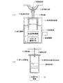
先ず、図1(a)に示す採血用具を使用した定量用溶液調製方法について説明する。
この場合、本発明は、図2(a)に示すように、採取された血液を用いて、血漿中の被測定物質を定量するための希釈血漿溶液からなる定量用溶液を調製する方法であって、(1)図1(a)に示す採血用具Aを使用して採取された血液を既知濃度の指示物質を含有する第1の希釈液12にて希釈する工程と、(2)この希釈血液溶液16を、分離手段Bにより血漿と細胞画分とに分離し、希釈血漿溶液17を調製する工程と、を含むことを特徴とするものである(請求項8)。
【0017】
この態様において、採血用具Aは、用具本体1に血液収容室2を備えていればよく、希釈液収容室10の有無は問わない。
従って、第1の希釈液による希釈工程は、採血用具A(血液収容室2+希釈液収容室10)内で行ってもよいし、別途定量用溶液調製器具で行ってもよい。
ここでいう第1の希釈液は、既知濃度の指示物質が含有されることを必要とする。
【0018】
また、本発明は、図2(a)に示すように、採取された血液を用いて、細胞画分中の被測定物質を定量するための希釈細胞画分溶液からなる定量用溶液を調製する方法であって、(1)図1(a)に示す採血用具Aを使用して採取された血液を第1の希釈液12で希釈する工程と、(2)この希釈血液溶液16を、分離手段Bにより血漿と細胞画分とに分離する工程と、(3)分離された細胞画分を第2の希釈液18で希釈し、希釈細胞画分溶液19を調製する工程と、を含むことを特徴とするものである(請求項9)。細胞画分中の被測定物質を定量する場合、被測定物質の濃度を測定する場合には、細胞画分の希釈細胞画分溶液19における希釈倍率を算出する必要があるため、第2の希釈液18中には既知濃度の指示物質を含有される。
また、本発明は、図2(a)に示すように、採取された血液を用いて、細胞画分中のヘモグロビンA1Cのヘモグロビンに対する割合を定量するための希釈細胞画分溶液からなる定量用溶液を調製する方法であって、(1)図1(a)に示す採血用具Aを使用し、血液収容室2内に血液を採取すると共に、採取された血液を第1の希釈液12で希釈する工程と、(2)この希釈血液溶液16を、分離手段Bにより血漿と細胞画分とに分離する工程と、(3)分離された細胞画分を第2の希釈液18で希釈し、希釈細胞画分溶液19を調製する工程と、を含むことを特徴とするものである(請求項10)。
【0019】
このような態様において、採血用具Aは、用具本体1に血液収容室2を備えていればよく、希釈液収容室10の有無は問わない。
従って、第1の希釈液12による希釈工程は、採血用具A(血液収容室2+希釈液収容室10)内で行ってもよいし、別途定量用溶液調製器具で行ってもよい。
また、通常、希釈血液溶液16を分離手段Bに通過させると、希釈血漿溶液17も調製されるが、ここでは、希釈血漿溶液17の調製の有無については問わない。
但し、希釈血漿溶液17からなる定量用溶液を調製する場合には、第1の希釈液12には、既知濃度の指示物質が含有されることを必要とする。
【0020】
次に、図1(b)に示す採血用具を使用した定量用溶液調製方法について説明する。
この場合、本発明は、図2(a)に示すように、採取された血液を用いて、血漿中の被測定物質を定量するための希釈血漿溶液からなる定量用溶液を調製する方法であって、(1)図1(b)に示す採血用具Aを使用して採取された血液を、希釈血液溶液収容室13内にて希釈血液溶液16として生成する工程と、(2)この希釈血液溶液16を、分離手段Bにより血漿と細胞画分とに分離し、希釈血漿溶液17を調製する工程と、を含むことを特徴とするものである(請求項11)。
また、本発明は、図2(a)に示すように、採取された血液を用いて、細胞画分中の被測定物質を定量するための希釈細胞画分溶液からなる定量用溶液を調製する方法であって、(1)図2(b)に示す採血用具Aを使用して採取された血液を第1の希釈液12で希釈する工程と、(2)この希釈血液溶液16を、分離手段Bにより血漿と細胞画分とに分離する工程と、(3)分離された細胞画分を第2の希釈液18で希釈し、希釈細胞画分溶液19を調製する工程と、を含むことを特徴とするものである(請求項12)。細胞画分中の被測定物質を定量する場合、被測定物質の濃度を測定する場合には、細胞画分の希釈細胞画分溶液19における希釈倍率を算出する必要があるため、第2の希釈液18中には既知濃度の指示物質が含有される。ここで、第2の希釈液18は、細胞画分を希釈するものであれば適宜選定して差し支えないが、細胞画分中の被測定物質を安定化する物質を含有する溶液であることが好ましい。
【0021】
また、本発明は、図2(a)に示すように、採取された血液を用いて、細胞画分中のヘモグロビンA1Cのヘモグロビンに対する割合を定量するための希釈細胞画分溶液からなる定量用溶液を調製する方法であって、(1)図1(b)に示す採血用具Aを使用し、希釈血液溶液収容室13内に希釈血液溶液16を生成する工程と、(2)この希釈血液溶液16を、分離手段Bにより血漿と細胞画分とに分離する工程と、(3)分離された細胞画分を第2の希釈液18で希釈し、希釈細胞画分溶液19を調製する工程と、を含むことを特徴とするものである(請求項13)。
ここで、第2の希釈液18は、細胞画分を希釈するものであれば適宜選定して差し支えないが、ヘモグロビン安定化剤を含有する溶液であることが好ましい。
【0022】
更に、本発明は、上述した定量用溶液調製方法を具現化した定量用溶液調製器具をも対象とする。
先ず、図1(a)に示す採血用具を使用した定量用溶液調製器具について説明する。
この場合、本発明は、図2(b)に示すように、図1(a)に示す採血用具Aと、この採血用具Aにて採取された血液から希釈血液溶液を生成した後、この希釈血液溶液から血漿と細胞画分とを分離する分離手段Bと、この分離手段Bにて分離調製された希釈血漿溶液からなる定量用溶液を収容する定量用溶液収容容器Cとを備えたことを特徴とするものである(請求項14)。
【0023】
また、図1(b)に示す採血用具のうち、容積可変機構14を備えた採血用具を使用した定量用溶液調製器具について説明する。
この場合、本発明は、図2(b)に示すように、図1(b)に示す容積可変機構14付き採血用具Aと、この採血用具Aにて採取、調製された希釈血液溶液から血漿と細胞画分とを分離する分離手段Bと、この分離手段Bにて分離調製された希釈血漿溶液からなる定量用溶液を収容する定量用溶液収容容器Cとを備えたことを特徴とするものである(請求項15)。
【0024】
ここで、前述した定量用溶液調製器具の代表的態様としては、分離手段Bは、定量用溶液収容容器Cの入口部分に設けられ、細胞画分を保持し且つ血漿を通過させるフィルタと、このフィルタの入口側に設けられて採血用具Aの希釈血液溶液収容室13に連通接続される連通部材とを備え、前記容積可変機構14により希釈血液溶液収容室13の容積を減少させることで、希釈血液溶液収容室13内の希釈血液溶液を前記分離手段Bに通過させ、定量用溶液収容容器Cに希釈血漿溶液からなる定量用溶液を調製するものが挙げられる(請求項16)。
尚、フィルタに保持された細胞画分については、第2の希釈液にて希釈することにより希釈細胞画分溶液からなる定量用溶液を調製し得る。
【0025】
また、この定量用溶液調製器具の使用方法としては、図1(b)に示す容積可変機構14付き採血用具Aを使用して採取された血液を、希釈血液溶液収容室13内にて希釈血液溶液として生成し、しかる後、採血用具Aの希釈血液溶液収容室13に分離手段Bの連通部材を連通接続した後、採血用具Aの容積可変機構14により希釈血液溶液収容室13の容積を減少させ、希釈血液溶液収容室13内の希釈血液溶液を前記分離手段Bに通過させ、定量用溶液収容容器Cに希釈血漿溶液からなる定量用溶液を調製するようにすればよい(請求項17)。
【0026】
更に、図1(b)に示す採血用具のうち、希釈血液溶液収容室13の容積が一定の態様(真空採血管内に第1の希釈液を収容した態様)の採血用具を使用した定量用溶液調製器具について説明する。
この場合、本発明は、図2(b)に示すように、内部に第1の希釈液が収容され、かつ、密封で減圧状態の希釈血液溶液収容室13が予め形成される用具本体11を有する図1(b)に示す採血用具Aと、この採血用具Aにて採取、調製された希釈血液溶液から血漿と細胞画分とを分離する分離手段Bと、密封で少なくとも採血用具Aの希釈血液溶液収容室13よりも減圧状態の定量用溶液収容室を有し、前記分離手段Bにて分離調製された希釈血漿溶液からなる定量用溶液を収容する定量用溶液収容容器Cとを備えたものが挙げられる(請求項18)。
【0027】
本態様において、定量用溶液収容容器Cは密封で採血用具Aの希釈血液溶液収容室13よりも減圧状態であることを必要とし、これにより、希釈血液溶液が分離手段(フィルタ)Bを介して定量用溶液収容容器C側に圧力差により移動する。
【0028】
ここで、前述した定量用溶液調製器具の代表的態様としては、分離手段Bは、細胞画分を保持し且つ血漿を通過させるフィルタと、このフィルタの入口側に設けられて前記希釈血液溶液収容室に連通接続される入口側連通部材と、フィルタの出口側に設けられて前記定量用溶液収容室に連通接続される出口側連通部材とを備え、採血用具Aの希釈血液溶液収容室13内の希釈血液溶液を前記分離手段Bに通過させ、定量用溶液収容容器Cに希釈血漿溶液からなる定量用溶液を調製するものが挙げられる(請求項19)。
尚、フィルタに保持された細胞画分については、第2の希釈液にて希釈することにより希釈細胞画分溶液からなる定量用溶液を調製し得る。
【0029】
また、この定量用溶液調製器具の使用方法としては、内部に第1の希釈液が収容され、かつ、密封で減圧状態の希釈血液溶液収容室が予め形成される用具本体を有する図1(b)に示す採血用具Aを使用して採取された血液を、希釈血液溶液収容室13内にて希釈血液溶液として生成し、しかる後、採血用具Aの希釈血液溶液収容室13に分離手段Bの入口側連通部材を連通接続した後、定量用溶液収容容器Cの定量用溶液収容室に前記分離手段Bの出口側連通部材を連通接続し、定量用溶液収容室と希釈血液溶液収容室13との圧力差により、採血用具Aの希釈血液溶液収容室13内の希釈血液溶液を前記分離手段Bに通過させ、定量用溶液収容容器Cに希釈血漿溶液からなる定量用溶液を調製するようにすればよい(請求項20)。
【0030】
また、本発明は、これらの定量用溶液調製方法にて調製された定量用溶液を用いた定量方法をも対象とする。
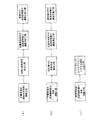
先ず、血漿中の被測定成分の定量方法の代表的態様を挙げると、本発明は、図3(a)に示すように、血液を用いて血漿中の被測定物質を定量する方法であって、(1)前述した定量用溶液調製方法にて希釈血漿溶液からなる定量用溶液を調製する工程と、(2)該定量用溶液中の指示物質の濃度と、第1の希釈液中の指示物質の濃度とから、該定量用溶液中の血漿の希釈倍率を算出する工程と、(3)該定量用溶液中の被測定物質の濃度を測定する工程と、(4)(2)で算出した希釈倍率と、(3)で測定した定量用溶液中の被測定物質の濃度とから、該血漿中の被測定物質の濃度を定量する工程と、を含むことを特徴とするものである(請求項21)。
【0031】
また、細胞画分中の被測定成分の定量方法の代表的態様を挙げると、本発明は、図3(b)に示すように、血液を用いて、細胞画分中の被測定物質を定量する方法であって、(1)前述した定量用溶液調製方法にて希釈細胞画分溶液からなる定量用溶液を調製する工程と、(2)該定量用溶液中の指示物質の濃度と、第2の希釈液中の指示物質の濃度とから、該定量用溶液中の細胞画分の希釈倍率を算出する工程と、(3)該定量用溶液中の被測定物質の濃度を測定する工程と、(4)(2)で算出した希釈倍率と、(3)で測定した定量用溶液中の被測定物質の濃度とから、該細胞画分中の被測定物質の濃度を定量する工程と、を含むことを特徴とするものである(請求項22)。
また、細胞画分中の被測定成分であるヘモグロビンA1Cのヘモグロビン対する割合を定量する方法の代表的態様を挙げると、本発明は、図3(c)に示すように、血液を用いて、細胞画分中のヘモグロビンA1Cのヘモグロビンに対する割合を定量する方法であって、(1)前述した定量用溶液調製方法にて希釈細胞画分溶液からなる定量用溶液を調製する工程と、(2)(1)で調製された定量用溶液におけるヘモグロビンA1Cのヘモグロビンに対する割合を定量する工程と、を含むことを特徴とするものである(請求項23)。
【0032】
【発明の実施の形態】
以下、添付図面に示す実施の形態に基づいて本発明を詳細に説明する。
◎実施の形態1
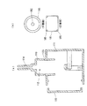
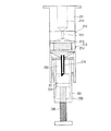
図4は本発明が適用された採血用具の実施の形態1の断面説明図、図5はその側面説明図である。
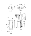
本実施の形態において、採血用具100は、血液収容室112を有する用具本体110と、この用具本体110に対して進退自在に設けられる穿刺体としての穿刺刃130と、この穿刺刃130を進退移動させる進退移動機構140と、この進退移動機構140に駆動エネルギを供給するエネルギ蓄積部材160と、前記進退移動機構140を初期位置に係脱させる係脱機構170と、進退移動機構140に連動して血液収容室112を減圧させる減圧機構180とを備えている。
【0033】
本実施の形態において、用具本体110は、例えば略ボックス状の合成樹脂製のハウジング111を有し、このハウジング111の頂部側には血液収容室112が区画される円筒状のシリンダ部113を設けると共に、このシリンダ部113の外側には血液収容室112に連通するノズル部114を突出形成したものである。
ここで、血液収容室112としては、採取される血液の量(通常1mL以下の少量でよい)に応じて適宜選定して差し支えなく、例えば5mL程度以下の容積を備えていればよい。
尚、ハウジング111の側面部の一部は、図5及び図6(a)に示すように、取り外し可能なカバー115にて構成されている。
更に、前記ノズル部114の先端部にはゴム製の吸盤116が設けられ、例えば人体の被採血部190(図11参照)周辺に吸着固定されるようになっている。
【0034】
また、前記シリンダ部113の外側には、図4及び図8に示すように、ドーナツ形状で且つチャンネル状に開口した希釈液収容室119が区画される希釈液収容環118がネジなどで嵌合装着されており、シリンダ部113と希釈液収容環118との間には連通孔120(本例では少なくとも一方側の連通孔120形状を長孔状とし、両者間の連通状態を確保する構造を採用)が適宜数(例えば4箇所)設けられ、更に、シリンダ部113と希釈液収容環118との間にはOリングなどのシール部材121が介装されている。尚、図6(a)中、符号123はシール部材121が収容されるシール溝である。
そしてまた、希釈液収容環118の開口部はリング状のラバーシール122にてハウジング111に対し液密に設けられている。
更にまた、希釈液収容室119には、攪拌性を考慮して、第1の希釈液21が満杯より少ない量だけ予め収容されている。
ここで、第1の希釈液21については、実施の形態2の定量用溶液の調製を説明する際に詳述する。
【0035】
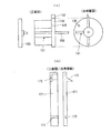
更に、穿刺刃130は通常金属製がよく、鋼鉄やステンレスが一般的である。
この穿刺刃130は前記ノズル部114内に進退自在に配設されており、進退移動機構140に連結されている。
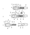
本実施の形態において、進退移動機構140は、ハウジング111内に回転自在に配設される回転板141と、この回転板141の中心位置から偏位した位置にピン連結され且つ前記穿刺刃130にピン連結されるリンク機構142とを備え、回転板141の回転動作に伴って穿刺刃130を進退動作させるようになっている。
ここで、リンク機構142としては、図7(a)〜(d)に示すように、2つのリンクアーム143,144を例えばボス145とエンボス146とを嵌合させる形式でピン連結し、一方のリンクアーム143の先端側に穿刺刃130をピン147連結すると共に、他方のリンクアーム144の先端側に弾性変形可能な接合ピン148を設け、前記回転板141の連結孔149(図9(a)参照)に接合ピン148を弾性嵌合させるものが用いられる。
また、回転板141の近傍には、回転板141の接合ピン148が当接して回転板141の回転範囲を規制するストッパ爪156が設けられている。
【0036】
また、本実施の形態において、回転板141の回転軸150には、図9(a)に示すように、羽根車状の駆動力伝達部151が設けられると共に、前記回転軸150の先端はハウジング111の外部に露呈し、この回転軸150の先端に操作ハンドル153が手動操作可能に連結されている。
更に、エネルギ蓄積部材160としては例えばゴムやバネ材が用いられ、前記回転板141に回転駆動力が付与されるようにエネルギ蓄積部材160が駆動力伝達部151に係合配設されている。
更にまた、前記回転板141の周囲の一部には係止突起152が設けられている。
【0037】
また、本実施の形態において、係脱機構170は、ハウジング111の底部に立設される弾性変形可能な範囲で傾動する係止部材171と、この係止部材171を傾動させる係止解除機構174とを備えている。
本実施の形態において、係止部材171は、図4及び図9(b)に示すように、回転板141の係止突起152と係脱する係止突起172を設け、かつ、その基端部には横方向からの荷重に対して傾動支点となる弾性凹部173を設けたものである。
一方、係止解除機構174は、図10(a)(b)に示すように、ハウジング111の一部にロッド取付部175を設け、このロッド取付部175にはロッド挿通孔176を設けると共に、このロッド挿通孔176に係止ロッド177を進退自在に挿通させ、この係止ロッド177の一部に弾性変形可能な位置決め凸部178を設け、前記ロッド取付部175に設けられた位置決め孔179に係脱させることを可能としたものであり、係止ロッド177を係止部材171側に押し込むことにより、係止部材171を係止ロッド177の押し込み方向に向けて傾動させ、前記回転板141と係止部材171との間で係止突起152,172の係止状態を解除するようにしたものである。
尚、本実施の形態では、前記回転板141と係止部材171との間で係止突起152,172が係止状態にある場合には、前記穿刺刃130が初期位置に配置されるようになっている。また、係止ロッド177は押し込み操作力を解除すると、係止部材171の弾性復帰力にて元の初期位置に戻るようになっている。
【0038】
また、本実施の形態において、減圧機構180は、図4及び図6(b)に示すように、前記シリンダ部113内に進退自在に配設されるピストン部181を有し、このピストン部181の中心部にはリンク機構142のリンクアーム143,144及び穿刺刃130が挿通する貫通孔182を設け、このピストン部181の貫通孔182部分には夫々Oリングからなるシール部材183,184を配設したものである。尚、シール部材183はリンク機構142のリンクアーム143の穿刺刃130側に巻装されてシリンダ部113とノズル部114との連結部位に配置され、また、シール部材184はリンク機構142のリンクアーム143のリンクアーム144側に巻装され且つリンクアーム143に固着されたストッパリング155(図7(a)参照)とピストン部181との間に配設されている。
また、図6(b)に示すように、ピストン部181の周囲には2条のシール溝185が設けられ、このシール溝185にOリング等のシール部材186が巻装され、シリンダ部113との間を液密に保つようになっている。
尚、ハウジング111やピストン部181等の素材については、滑り易さやOリングなどのシール部材の弾性を考慮し、適宜選定して差し支えないが、例えばプラスチックとしては、ポリプロピレン、ポリエチレン、ポリカーボネート、尿素樹脂、フェノール樹脂、ポリエステル、ナイロン樹脂、ポリスチレン、アクリル、ポリウレタン、合成ゴム、フッ素樹脂、シリコン樹脂等、市販のポリマーの中から選択してよい。
【0039】
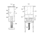
次に、本実施の形態に係る採血用具の使用方法について説明する。
今、図11に示すように、人体の被採血部190を覆うように吸盤116を吸い付けた状態で採血用具100をセットする。
この状態で、係脱機構170は係止状態を保持しており、穿刺刃130を初期位置に位置決めすると共に、エネルギ蓄積部材160は回転板141に回転駆動力を付与した状態に保持されている。
この後、係脱機構170の係止ロッド177を押し込み操作すると、回転板141と係止部材171との間の係止突起152,172同士の係止状態が解除され、エネルギ蓄積部材160からの回転駆動力が駆動力伝達部151を介して回転板141に伝達され、回転板141を矢印方向に回転させる。
【0040】
このとき、本実施の形態では、回転板141が約1/4回転すると、回転板141とリンク機構142とのピン連結部が最も上昇した位置に移動する。
すると、リンク機構142に連結されている穿刺刃130は、ノズル部114より突出し、人体の被採血部190に穿刺される。
この場合、穿刺刃130は、元々ノズル部114内に隠れており、係脱機構170の係止解除操作を行うだけで、穿刺刃130が一瞬だけ被採血部190を穿刺するため、採血用具100を使用しているユーザーが精神的に恐怖感を受けることはない。
【0041】
特に、本実施の形態において、エネルギ蓄積部材160からのエネルギが、回転板141のピン連結部がストッパ爪156に当接するまで回転板141に回転駆動力を与えるものであるとすれば、図12に示すように、回転板141は約3/4回転した後にストッパ爪156にて強制停止せしめられるが、この回転板141が約1/4回転以降回転すると、穿刺刃130は穿刺位置から退避位置へと退避動作していく。
従って、穿刺刃130が被採血部190を穿刺するのは瞬間的であるから、穿刺刃130による穿刺動作がユーザーに大きな痛みを与える懸念は少ない。
【0042】
また、図12に示すように、穿刺刃130が退避動作するとき、リンク機構142と共に、リンク機構142に巻装されているシール部材183がピストン部181の頂部に突き当たる。
すると、ピストン部181が当該シール部材183を介してシリンダ部113内で後退することになり、このピストン部181の移動に伴って、吸盤116によって密封されている血液収容室112が減圧せしめられる。
この状態において、穿刺刃130によって傷つけられた被採血部190から血液が負圧によって、ノズル部114と穿刺刃130との隙間を通じて血液収容室112側に吸引収容されていく。
【0043】
そして、ピストン部181がある程度後退すると、血液収容室112と希釈液収容室119とが連通孔120を介して連通する状態になり、血液収容室112内に吸引収容された血液Mは第1の希釈液21によって順次希釈される。
この段階において、採血用具100の血液収容室112には希釈血液溶液が所定量収容される。
【0044】
この後、採血用具100にて採取した希釈血液溶液を用いて、定量用溶液を調製するような場合には、図13に示すように、希釈血液溶液が収容される別容器30を用意し、これに対向するように、採血用具100を配置する。
この状態で、操作ハンドル153を所定方向に回転操作すると、リンク機構142を介して穿刺刃130が進出動作すると共に、リンク機構142を介してシール部材184がピストン部181の底部側に突き当たり、このシール部材184を介してシリンダ部113内でピストン部181が押し出す方向に移動する。すると、ピストン部181の押出動作に伴って、血液収容室112内の希釈血液溶液がピストン部181で押し出され、容器30に移される。
この後、容器30内の希釈血液溶液を用いて、定量用溶液の調製作業が行われる(実施の形態2参照)。
【0045】
尚、本実施の形態においては、採血用具100としては、血液収容室112に連通接続される希釈液収容室119を備えたものが用いられているが、これに限られるものではなく、図14に示すように、用具本体110に希釈液収容室119を設けない態様についても適用して差し支えなく、この態様にあっては、血液収容室112には希釈されていない血液が収容されることになるため、採取された血液は別途迅速に希釈された後に、定量用溶液を調製することが好ましい。
【0046】
◎実施の形態2
本実施の形態は、実施の形態1に係る採血用具100を使用し、定量用溶液を調製する方法について説明する。
本実施の形態において、定量用溶液調製器具は、実施の形態1で使用される採血用具100と、図15に示される定量用溶液調製用具とを備えている。
本実施の形態において、定量用溶液調製用具は、血漿中の被測定物質または細胞画分中の被測定物質を定量するための定量用溶液を調製するための用具であり、図15に示すように、相互に嵌合可能な第1容器30及び第2容器40からなる。尚、図15(a)は第1容器30の正面図及び平面図、図15(b)は第2容器40の正面図及び平面図である。
ここで、第1容器30及び第2容器40は、プラスチック製が望ましく、材質としては、ポリエチレンやポリプロピレン、ポリカーボネイト、塩化ビニル、ポリエステル、ナイロン、ポリブデン、ポリブタジエン、あるいは、これらの共重合体などが挙げられる。
【0047】
先ず、第1容器30について説明すると、第1容器30は、例えば円柱状の容器本体31を有し、この容器本体31には希釈血液溶液22(図16参照)又は第2の希釈液28(図17参照)が収容せしめられる希釈血液溶液収容部32(希釈血液溶液収容室33を区画する部分に相当)を設け、希釈血液溶液収容部32の内壁、言い換えれば、希釈血液溶液収容室33壁面入口側には雌ねじ部34を形成する一方、前記容器本体31の底部には下方へ突出する固定スタッド35を形成し、この固定スタッド35を図示外の固定ホルダのねじ孔部に係合固定することにより、固定ホルダに固定設置されるようになっている。
尚、容器本体31の入口部には後述する第2容器40の定量用溶液収容部42と嵌合部44との段差部が当接するフランジ部36が設けられている。
【0048】
一方、第2容器40は、例えば円柱状の容器本体41を有し、この容器本体41には定量用溶液(希釈血漿溶液又は希釈細胞画分溶液)が収容せしめられる定量用溶液収容部42(定量用溶液収容室43を区画する部分に相当)を設け、更に、この定量用溶液収容部42に隣接した箇所には第1容器30側に向かって突出し且つ前記第1容器30の希釈血液溶液収容部32に嵌合する嵌合部44を設け、この嵌合部44には先端から定量用溶液収容部42に向かって連通する連通部45を形成したものである。
本実施の形態において、定量用溶液収容部42は、円柱状形状にくりぬかれた収容室部分と、この下方に隣接して下方に向かって窄まるように円錐状形状にくりぬかれた収容室部分とからなる定量用溶液収容室43を備えている。
また、前記嵌合部44は定着用溶液収容部42よりも小さな外径を有し、その周壁には第1容器30の希釈血液溶液収容部32の雌ねじ部34に螺合する雄ねじ部46を形成したものである。
更に、連通部45は、嵌合部44の先端側から所定の内径に形成されるフィルタ保持孔47と、このフィルタ保持孔47よりも小径で前記定量用溶液収容室43の下端部に連通接続される小径接続孔48とを備えたものである。
【0049】
また、本実施の形態において、第2容器40のフィルタ保持孔47にはフィルタ60が挿入保持されており、このフィルタ60はフィルタ保持孔47より所定量m突出して配設されている。
本実施の形態において、フィルタ60は例えば微細繊維集合体、多孔質ポリマー又は微粒子集合体にて構成されており、例えば微細繊維集合体又は微粒子集合体を使用する態様にあっては、血漿以外の細胞画分が捕獲され、多孔質ポリマー、多孔質ポリマーが混在する微細繊維集合体又は多孔質ポリマーが混在する微粒子集合体を使用する態様にあっては、表面に細胞画分を保持し、内部に希釈血漿溶液を保持するようになっている。
尚、多孔質ポリマーのうち、特に、高吸水性に優れたものとしては、例えばポリアクリル酸樹脂、ポリエチレンオキシド樹脂、酢酸ビニル共重合体系樹脂、アクリル酸グラフト共重合体系樹脂などが挙げられる。
特に、本実施の形態では、嵌合部44の長さ寸法k及びフィルタ60の嵌合部44からの突出部寸法mの合計は、第1容器30の希釈血液溶液収容部32の深さ寸法nに対応して設定されている。
更に、前記嵌合部44の先端側周囲には周辺シール部材としてのOリング49が設けられている。
【0050】
更にまた、本実施の形態では、第2容器40の定量用溶液収容部42の上方側には当該定量用溶液収容部42の上方を開放可能に覆う蓋部材50が設けられている。
この蓋部材50は、定量用溶液収容部42の上方突出部42aに嵌合する凹部51を有し、この凹部51の内面には前記上方突出部42aに形成された雄ねじ部42bに螺合する雌ねじ部52を備えている。
そして、この蓋部材50は大気に連通する微小な大気開放口53を有している。
更にまた、本実施の形態では、容器本体41の定量用溶液収容部42の外周にはフランジ状の支持片54が設けられている。
この支持片54は、例えば自動分析装置に本件の調製用具を設置する際にサンプルテーブルの設置個所に調製用具を支えるためのものである。
【0051】
また、本実施の形態及び本件において使用する用語については以下のように意義を明確にしておく。
(血漿と細胞画分)
血液は、血漿と細胞画分から成り立っており、細胞画分には赤血球、白血球、血小板等が含有される。本発明において、血漿は本来の意味での血漿だけでなく、血液凝固反応によって凝集したフィブリンを除いた本来の意味での血清をも表す。以下、血清および血漿を合わせて、血漿とよぶこととする。また、本発明において、血液凝固反応が起こった場合には、細胞画分は血餅をも表す。以下、細胞画分及び血液凝固反応が起こった場合の血餅を合わせて、細胞画分とよぶこととする。
【0052】
(血漿中の被測定物質、細胞画分中の被測定物質)
血漿中の被測定物質としては、生化学項目や免疫項目のいずれの項目も適用可能である。生化学項目としては、例えば、グルコース、1,5−アンヒドログルシトール、フコース、尿素、アンモニア、クレアチニン、総コレステロール、HDLコレステロール、LDLコレステロール、RLPコレステロール、トリグリセライド、リン脂質、Na、K、Cl、Ca、総蛋白、アルブミン、グロブリン、ビリルビン、胆汁酸、シアル酸、遊離脂肪酸、アラニンアミノトランスフェラーゼ(ALT)、アスパラギン酸アミノトランスフェラーゼ(AST)、クレアチンホスホキナーゼ(CPK)、ホスホキナーゼ(PK)、アミラーゼ、リパーゼ、コリンエステラーゼ、γ−グルタミルトランスペプチダーゼ、L−乳酸デヒドロゲナーゼ(LDH)、アルドラーゼ、アルカリフォスファターゼ、酸フォスファターゼ等が挙げられる。免疫項目としては、例えば、IgG、IgM、IgA、IgE、アポ蛋白AI、アポ蛋白AII、アポ蛋白B、アポ蛋白E、リューマチファクター、D−ダイマー、酸化LDL、グリコアルブミン、T3、T4、抗テンカン剤などの薬剤、α−フェトプロテイン(AFP)、癌胎児性抗原(CEA)、CA19−9、CA−125、BNP、トロポニンT、トロポニンI、ヒト絨毛性ゴナドトロピン(hCG)、インスリン、C−ペプタイド、エストロゲン、抗GAD抗体、ペプシノーゲン、HB抗原、抗HB抗体、HCV抗原、抗HCV抗体、HTLV−I抗原、抗HTLV−I抗体、HIV抗体、結核抗体、マイコプラズマ抗体等が挙げられる。細胞画分中の被測定物質としては、例えば、ヘモグロビンA1C等が挙げられる。
【0053】
(第1の希釈液)
第1の希釈液は、血漿中の被測定物質を測定する場合に使用する、血液を希釈・溶解するための水性溶液であり、希釈倍率算出のための指示物質が一定濃度で含有される水性溶液である。
(第1の希釈液調製用水性媒体)
第1の希釈液を調製するために使用する水性媒体としては、溶血させずに血液を安定に保存するものであれば特に制限はないが、例えば、等張液、生理食塩水、緩衝液等が挙げられる。等張液としては、例えば、ロック液、リンガー液、タイロード液、アール液、クレブス液、リン酸緩衝化生理食塩水(PBS)等が挙げられる。生理食塩水中の塩化ナトリウムの濃度は、0.1〜0.2mol/Lである。緩衝液に用いる緩衝剤としては、緩衝能を有するものならば特に制限されないが、pH2〜11の例えば、乳酸緩衝剤、クエン酸緩衝剤、酢酸緩衝剤、コハク酸緩衝剤、フタル酸緩衝剤、リン酸緩衝剤、トリエタノールアミン緩衝剤、ジエタノールアミン緩衝剤、リジン緩衝剤、バルビツール緩衝剤、トリス(ヒドロキシメチル)アミノメタン緩衝剤、イミダゾール緩衝剤、リンゴ酸緩衝剤、シュウ酸緩衝剤、グリシン緩衝剤、ホウ酸緩衝剤、炭酸緩衝剤、グリシン緩衝剤、MES(2−モルホリノエタンスルホン酸)緩衝剤、ビス−トリス[ビス(2−ヒドロキシエチル)イミノトリス(ヒドロキシメチル)メタン]緩衝剤、ADA[N−(2−アセトアミド)イミノ二酢酸]緩衝剤、PIPES[ピペラジン−N,N’−ビス(2−エタンスルホン酸)]緩衝剤、ACES{2−[N−(2−アセトアミド)アミノ]エタンスルホン酸}緩衝剤、MOPSO(3−モルホリノ−2−ヒドロキシプロパンスルホン酸)緩衝剤、BES{2−[N,N−ビス(2−ヒドロキシエチル)アミノ]エタンスルホン酸}緩衝剤、MOPS(3−モルホリノプロパンスルホン酸)緩衝剤、TES〈2−{N−[トリス(ヒドロキシメチル)メチル]アミノ}エタンスルホン酸〉緩衝剤、HEPES[N−(2−ヒドロキシエチル)−N’−(2−スルホエチル)ピペラジン]緩衝剤、DIPSO{3−[N,N−ビス(2−ヒドロキシエチル)アミノ]−2−ヒドロキシプロパンスルホン酸}緩衝剤、TAPSO〈2−ヒドロキシ−3−{[N−トリス(ヒドロキシメチル)メチル]アミノ}プロパンスルホン酸〉緩衝剤、POPSO[ピペラジン−N,N’−ビス(2−ヒドロキシプロパン−3−スルホン酸)]緩衝剤、HEPPSO[N−(2−ヒドロキシエチル)−N’−(2−ヒドロキシ−3−スルホプロピル)ピペラジン]緩衝剤、EPPS[N−(2−ヒドロキシエチル)−N’−(3−スルホプロピル)ピペラジン]緩衝剤、トリシン[N−トリス(ヒドロキシメチル)メチルグリシン]緩衝剤、ビシン[N,N−ビス(2−ヒドロキシエチル)グリシン]緩衝剤、TAPS{3−[N−トリス(ヒドロキシメチル)メチル]アミノプロパンスルホン酸}緩衝剤、CHES[2−(N−シクロヘキシルアミノ)エタンスルホン酸]緩衝剤、CAPSO[3−(N−シクロヘキシルアミノ)−2−ヒドロキシプロパンスルホン酸]緩衝剤、CAPS[3−(N−シクロヘキシルアミノ)プロパンスルホン酸]緩衝剤等のグッド緩衝剤等が挙げられる。緩衝液の濃度は特に制限はされないが、0.1〜1000mmol/Lが好ましく1〜500mmol/Lがより好ましい。
【0054】
(第1の希釈液中の添加物)
第1の希釈液には必要に応じて、キレート剤、酵素安定化剤、防腐剤、凝固促進剤等の添加物が含有されてもよい。キレート剤としては、例えば、エチレンジアミン四酢酸(EDTA)等が挙げられ、酵素安定化剤としては、例えば、CPKの安定化剤としてのN−アセチルシステイン(NAC)、ALT、AST、CPKの安定化剤としてのα−ケトグルタル酸等が挙げられる。防腐剤としては、例えば、アジ化ナトリウム等が挙げられる。凝固促進剤としては、例えば、トロンビン、レクチン等が挙げられる。レクチンの由来としては、例えば、アブリン、トウアズキ、モクワンジュ、シベリア豆、海緑藻、タチナタ豆、大豆、スイートピー、レンズ豆、カブトガニ、トマト、オセージオレンジ、アボガド、ベニバナインゲンハナササゲ、赤インゲン豆、アメリカヤマゴボウ、エンドウ豆、ウィングビーン、ヒマ、ジャガイモ、コムギ麦芽、ソラ豆、ヨーロッパヤドリギ等が挙げられる。
【0055】
外因性指示物質としては、例えば、色素、還元発色型色原体、酸化発色型色原体、蛍光物質、発光物質等が挙げられる。酸化発色型色原体としては、ロイコ型色原体、酸化カップリング発色型色原体が挙げられる。これらのうち、酸化カップリング発色型色原体が好ましい。
【0056】
(色素)
色素としては、例えば、アシッドイエロー3、アシッドイエロー23、アシッドイエロー25、アシッドイエロー36、アシッドオレンジ5、アシッドオレンジ6、アシッドオレンジ7、アシッドオレンジ10、アシッドオレンジ19、アシッドオレンジ52、アシッドグリーン16、アシッドグリーン25、アシッドバイオレット43、アシッドブルー3、アシッドブルー9(ブリリアントブルーFCF)、アシッドブルー40、アシッドブルー45、アシッドブルー47、アシッドブルー59、アシッドブルー74、アシッドブルー113、アシッドブルー158、アシッドレッド1、アシッドレッド2、アシッドレッド14、アシッドレッド18、アシッドレッド27、アシッドレッド37、アシッドレッド51、アシッドレッド52、アシッドレッド87、アシッドレッド88、アシッドレッド92、アシッドレッド94、アシッドレッド95、アシッドレッド111、フードレッド17、フードイエロー3、ベーシックイエロー1、ベーシックイエロー2、ベーシックイエロー11、ベーシックオレンジ1、ベーシックオレンジ22、ベーシックグリーン4(マラカイトグリーン)、ベーシックバイオレット3、ベーシックバイオレット4、ベーシックバイオレット10、ベーシックブルー1、ベーシックブルー3、ベーシックブルー9、ベーシックブルー24、ベーシックレッド1、ベーシックレッド2、ベーシックレッド5、ベーシックレッド9、ベーシックレッド18等が挙げられる。
【0057】
(還元発色型色原体)
還元発色型色原体としては、例えば、3−(4,5−ジメチル−2−チアゾリル)−2,5−ジフェニル−2H−テトラゾリウム ブロミド(MTT)、2−(4−ヨードフェニル)−3−(4−ニトロフェニル)−5−(2,4−ジスルホフェニル)−2H−テトラゾリウム モノナトリウム塩(WST−1)、2−(4−ヨードフェニル)−3−(2,4−ジニトロフェニル)−5−(2,4−ジスルホフェニル)−2H−テトラゾリウム モノナトリウム塩(WST−3)等が挙げられる。
(酸化発色型色原体〜ロイコ型色原体)
ロイコ型色原体は、過酸化水素およびペルオキシダーゼ等の過酸化活性物質の共存下、単独で色素へ変換される色原体であり、例えば、10−N−カルボキシメチルカルバモイル−3,7−ビス(ジメチルアミノ)−10H−フェノチアジン(CCAP)、10−N−メチルカルバモイル−3,7−ビス(ジメチルアミノ)−10H−フェノチアジン(MCDP)、N−(カルボキシメチルアミノカルボニル)−4,4’−ビス(ジメチルアミノ)ジフェニルアミン ナトリウム塩(DA−64)、4,4’−ビス(ジメチルアミノ)ジフェニルアミン、ビス[3−ビス(4−クロロフェニル)メチル−4−ジメチルアミノフェニル]アミン(BCMA)等が挙げられる。
【0058】
(酸化発色型色原体〜酸化カップリング発色型色原体)
酸化カップリング発色型色原体は、過酸化水素およびペルオキシダーゼ等の過酸化活性物質の共存下、2つの化合物が酸化的カップリングして色素を生成する色原体である。2つの化合物の組み合わせとしては、カプラーとアニリン類との組み合わせ、カプラーとフェノール類との組み合わせが挙げられる。カプラーとしては、例えば、4−アミノアンチピリン(4−AA)、3−メチル−2−ベンゾチアゾリノンヒドラジン等が挙げられる。アニリン類としては、N−エチル−N−(3−メチルフェニル)−N’サクシニルエチレンジアミン(EMSE)、N−(3,5−ジメトキシフェニル)−N’サクシニルエチレンジアミン・ナトリウム塩(DOSE)、N−エチル−N−(2−ヒドロキシ−3−スルホプロピル)−m−トルイジン、N−エチル−N−スルホプロピルアニリン、N−エチル−N−スルホプロピル−3,5−ジメトキシアニリン、N−スルホプロピル−3,5−ジメトキシアニリン、N−エチル−N−スルホプロピル−3,5−ジメチルアニリン、N−エチル−N−スルホプロピル−m−トルイジン、N−エチル−N−(2−ヒドロキシ−3−スルホプロピル)−m−アニシジン、N−エチル−N−(2−ヒドロキシ−3−スルホプロピル)アニリン、N−エチル−N−(2−ヒドロキシ−3−スルホプロピル)−3−メチルアニリン・ナトリウム塩2水和物(TOOS)、N−エチル−N−(2−ヒドロキシ−3−スルホプロピル)−3,5−ジメトキシアニリン、N−(2−ヒドロキシ−3−スルホプロピル)−3,5−ジメトキシアニリン・ナトリウム塩(HSDA)、N−エチル−N−(2−ヒドロキシ−3−スルホプロピル)−3,5−ジメチルアニリン、N−スルホプロピルアニリン、N−エチル−N−スルホプロピルアニリンプロピル−m−アニジン、N−エチル−N−(2−ヒドロキシ−3−スルホプロピル)−4−フルオロ−3,5−ジメトキシアニリン・ナトリウム塩(F−DAOS)等が挙げられる。フェノール類としては、フェノール、3−ヒドロキシ−2,4,6−トリヨウド安息香酸等が挙げられる。
【0059】
(蛍光物質及び発光物質)
蛍光物質としては、例えば、4−ヒドロキシフェニル酢酸、3−(4−ヒドロキシフェニル)プロピオン酸、クマリン等が挙げられる。発光物質としては、例えば、ルミノール、イソルミノール、ルシゲニン、アクリジニウムエステル等が挙げられる。
【0060】
(第2の希釈液)
第2の希釈液としては、例えば、蒸留水や塩濃度の低い水溶液等の低張液が挙げられる。第2の希釈液には、必要に応じて、指示物質、ヘモグロビン安定化剤、界面活性剤、脂質加水分解酵素等が含有される。細胞画分中の被測定物質を定量する場合には、特に、細胞画分中の被測定物質を濃度として測定する場合には、指示物質が含有される。指示物質としては上記のものが挙げられる。また、細胞画分中のヘモグロビンA1Cのヘモグロビンに対する割合を定量する場合には、第2の希釈液にはヘモグロビン安定化剤が含有されることが好ましい。
(ヘモグロビン安定化剤)
ヘモグロビン安定化剤としては、例えば、糖類、アミノ酸類、プロテアーゼ阻害剤、キレート剤、鉄プロトポルフィリン、フッ化ナトリウム、アルブミン類、ハプトグロブリン等が挙げられる。界面活性剤としては、例えば、ノニオン性界面活性剤、カチオン性界面活性剤、アニオン性界面活性剤、両性界面活性剤等が挙げられる。脂質加水分解酵素としては、例えば、ホスホリパーゼ類やリポプロテインリパーゼ等が挙げられる。
【0061】
(フィルタ)
本実施の形態では、分離手段としてフィルタ60が用いられている。このフィルタ60としては、微細繊維集合体、多孔質ポリマー又は微粒子集合体が挙げられる。
(微細繊維集合体)
微細繊維集合体としては、例えば、ガラス繊維集合体、セルロース繊維集合体、合成繊維集合体等が挙げられる。合成繊維集合体の材質としては、例えば、ポリエチレン、ポリプロピレン、ポリスチレン、ポリアミド、ポリスルホン、ポリウレタン、ポリビニルホルマール、ポリ塩化ビニル、ポリエステル類等が挙げられる。必要に応じて、親水処理が施された微細繊維集合体も用いることができる。
(多孔質ポリマー及び微粒子集合体)
多孔質ポリマーとしては、例えば、熱硬化性ポリマー(フェノール系、尿素系、メラミン系、アルキド系、ポリエステルイソシアナート系)、熱可塑性ポリマー(ポリビニルホルマール、ポリ塩化ビニル、ポリスチレン、ポリエチレン)、セルロース誘導体(エステル体、エーテル体、ビスコース)等が挙げられる。微粒子集合体としては、例えば、シリカ微粒子集合体等が挙げられる。
【0062】
次に、本実施の形態に係る定量用溶液調製用具の使用方法について説明する。
(希釈血漿溶液からなる定量用溶液の調製方法1)
今、第2容器40のフィルタ保持孔47にフィルタ60として微細繊維集合体を挿入保持させた実施の形態モデルを使用する場合を想定する。
この場合、図16(a)に示すように、第1容器30の希釈血液溶液収容部32に希釈血液溶液(例えば実施の形態1参照)22を収容し、しかる後、図16(b)(c)に示すように、第1容器30と第2容器40とを嵌合させ、第2容器40の定量用溶液収容部42に希釈血漿溶液25からなる定量用溶液を調製する。
【0063】
本例の場合、第2容器40の嵌合部44が第1容器30の希釈血液溶液収容部32に嵌合していき、前記フィルタ60の先端が希釈血液溶液22に浸漬すると、第1容器30に第2容器40を押し込んでいる間、蓋部材50の大気開放口53が開放されているため、この大気開放口53から空気が逃げ、希釈血液溶液22はフィルタ60を介して定量用溶液収容部42側へと移動する。
このとき、希釈血液溶液22中の細胞画分Sはフィルタ60である微細繊維集合体の表面に保持されるため、希釈血液溶液22のうち、血漿がフィルタ60を透過して定量用溶液収容部42に移動する。
このため、定量用溶液収容部42には希釈血漿溶液25からなる定量用溶液が調製される。
また、図15に示すように、連通部45のうち、小径接続孔48はフィルタ保持孔47に保持されているフィルタ60と定量用溶液収容部42とを連通接続するが、その径が非常に細いため、定量用溶液収容部42内の定量用溶液とフィルタ60に残っている液とが混在することはない。
【0064】
(希釈細胞画分溶液からなる定量用溶液の調製方法1)
今、第2容器40のフィルタ保持孔47にフィルタ60として微細繊維集合体を挿入保持させた実施の形態モデルを使用する場合を想定する。
この場合、図16(a)に示すように、第1容器30の希釈血液溶液収容部32に希釈血液溶液22を収容させ、しかる後、図16(b)(c)に示すように、第1容器30と第2容器40とを嵌合させ、第2容器40の定量用溶液収容部42に希釈血漿溶液25からなる定量用溶液を調製し、次いで、図17(a)に示すように、第1容器30及び第2容器40の嵌合状態を解除した後に、前記第2容器40の定量用溶液収容部42から前記希釈血漿溶液25からなる定量用溶液を取り除き、一方、第1容器30の希釈血液溶液収容部32に所定量の第2の希釈液28を収容し、しかる後、図17(b)(c)に示すように、第1容器30と第2容器40とを嵌合させ、第2容器40の定量用溶液収容部42に希釈細胞画分溶液27からなる定量用溶液を調製する。
【0065】
このような調製方法において、希釈細胞画分溶液27を調製する段階において、第2容器40の定量用溶液収容部42については、希釈血漿溶液25の影響が及ばないように、洗浄した後に使用することが好ましい。
また、第1容器30には第2の希釈液28を収容することになるが、希釈血液溶液22の影響が及ばないようにするには第1容器30も洗浄後に第2の希釈液28を収容させるようにするか、あるいは、第1容器30として別パーツのものを使用することが好ましい。
この調製方法では、図17(b)(c)のように、第1容器30と第2容器40とを嵌合させると、第2の希釈液28がフィルタ60表面に保持された細胞画分Sを希釈し、定量用溶液収容部42へと移動していく。
【0066】
◎実施の形態3
図18は本発明が適用された定量用溶液調製器具の実施の形態3を示す。
同図において、定量用溶液調製器具は、図18(a)に示す採血用具200と、図18(b)に示す定量用溶液調製用具210とからなる。
本実施の形態において、採血用具200は、採血管201の内部に第1の希釈液21が収容される希釈血液溶液収容室202を形成し、この採血管201の開口部を例えばゴム状膜からなる封止体203にて密閉状に封止すると共に、この採血管201には希釈血液溶液収容室202の容積を可変にするピストン204を例えばネジ状の進退操作ロッド205を回転することにより進退自在に設けたものである。
【0067】
一方、定量用溶液調製用具210は、上部が開口した定量用溶液収容室212が形成された定量用溶液収容容器211を有し、この定量用溶液収容容器211の下部に分離デバイス213を取り付けたものである。
この分離デバイス213は、内部に連通路が形成された連通ホルダ215内にフィルタ214を配設し、この連通ホルダ215の下部には中空針216を突出配置すると共に、前記定量用溶液収容容器211の下部に分離デバイス213の連通路に連通する連通孔217を設けたものである。
尚、フィルタ214は、希釈血液溶液22内の細胞画分を保持し、血漿を通過させるものである。
【0068】
このような定量用溶液調製器具の使用方法について説明すると、以下のようである。
先ず、採血用具200を用いて採血する場合には、図19に示すように、採血用具200の進退操作ロッド205を後退させ、希釈血液溶液収容室202の容積を増加させることで、希釈血液溶液収容室202を減圧状態とし、この状態で、人体の被採血部に両端が穿刺可能な中空針206を穿刺すると共に、この中空針206の他方を前記採血用具200の封止体203に突き刺すようにすればよい。
このようにすれば、被採血部から流出した血液は、負圧状態の希釈血液溶液収容室202内に吸引収容されると同時に、内部の第1の希釈液21にて希釈される。
この状態で、採血用具200内には、希釈血液溶液が調製される。
【0069】
次に、定量用溶液調製用具210について説明すると、図20に示すように、希釈血液溶液22が収容された採血用具200の封止体203に分離デバイス213の中空針216を突き刺し、この状態で、採血用具200の進退操作ロッド205を進出させ、希釈血液溶液収容室202内の希釈血液溶液22を正圧で押し出すことにより、分離デバイス213のフィルタ214に希釈血液溶液22を通過させるようにすればよい。
このようにすれば、定量用溶液収容容器211の定量用溶液収容室212にフィルタ214を通過した希釈血漿溶液からなる定量用溶液が収容される。
尚、フィルタ214には、細胞画分が捕獲されており、仮に、希釈細胞画分溶液からなる定量用溶液を調製する場合には、フィルタ214に第2の希釈液を通過させることで、フィルタ214に捕獲されている細胞画分を希釈し、希釈細胞画分溶液として調製するようにすればよい。
【0070】
◎実施の形態4
図21は本発明が適用された定量用溶液調製器具の実施の形態4を示す。
同図において、定量用溶液調製器具は、図21(a)に示す採血用具300と、図21(b)に示す分離デバイス310と、図21(c)に示す定量用溶液収容管320とからなる。
本実施の形態において、採血用具300は、採血管301の内部に第1の希釈液21が収容される希釈血液溶液収容室302を形成し、この希釈血液溶液収容室302を予め負圧状態に真空吸引すると共に、採血管301の開口部を例えばゴム状膜からなる封止体303にて密閉状に封止したものである。
【0071】
一方、分離デバイス310は、連通ホルダ311内の連通路にフィルタ312を配設し、連通ホルダ311の上下には入口側中空針313及び出口側中空針314を突出形成したものである。
更に、定量用溶液収容管320は内部に定量用溶液収容室322を形成したもので、この定量用溶液収容室322を予め負圧状態に真空吸引すると共に、開口部を例えばゴム状膜からなる封止体323にて密閉状に封止したものである。
特に、定量用溶液収容管320の負圧状態は少なくとも希釈血液溶液が調製された採血管301よりも真空度が大きくなるように設定される。
【0072】
このような定量用溶液調製器具の使用方法について説明すると、以下のようである。
先ず、採血用具300を用いて採血する場合には、図22に示すように、人体の被採血部に両端が穿刺可能な中空針306を穿刺すると共に、この中空針306の他方を前記採血用具300の封止体303に突き刺すようにすればよい。
このようにすれば、被採血部から流出した血液は、負圧状態の希釈血液溶液収容室302内に吸引収容されると同時に、内部の第1の希釈液21にて希釈される。
この状態で、採血用具300内には、希釈血液溶液が調製される。
【0073】
次に、定量用溶液を調製する場合について説明すると、図23(a)(b)(c)に示すように、希釈血液溶液22が収容された採血用具300の封止体303に分離デバイス310の入口側中空針313を突き刺し、この後、分離デバイス310の出口側中空針314を定量用溶液収容管320の封止体323に突き刺すようにすればよい。
このとき、定量用溶液収容管320の方が採血管301に比べて負圧状態が高いので、気体の圧力差により、採血管301内の希釈血液溶液22が分離デバイス310のフィルタ312を通過して定量用溶液収容管320に吸い出される。この結果、定量用溶液収容管320の定量用溶液収容室322にフィルタ312を通過した希釈血漿溶液からなる定量用溶液が収容される。
尚、フィルタ312には、細胞画分が捕獲されており、仮に、希釈細胞画分溶液からなる定量用溶液を調製する場合には、フィルタ312に第2の希釈液を通過させることで、フィルタ312に捕獲されている細胞画分を希釈し、希釈細胞画分溶液として調製するようにすればよい。
【0074】
◎実施の形態5
本実施の形態は、各実施の形態で調製された定量用溶液を用いた定量方法を示す。
これは、血液を用いて血漿中の被測定物質を定量する方法であって、
(1)上述した定量用溶液調製方法にて希釈血漿溶液からなる定量用溶液を調製する工程と、
(2)該定量用溶液中の指示物質の濃度と、第1希釈用溶液中の指示物質の濃度とから、該定量用溶液中の血漿の希釈倍率を算出する工程と、
(3)該定量用溶液中の被測定物質の濃度を測定する工程と、
(4)(2)で算出した希釈倍率と、(3)で測定した定量用溶液中の被測定物質の濃度とから、該血漿中の被測定物質の濃度を定量する工程と、
を含むものである(図3(a)参照)。
以下、本実施の形態における定量方法について詳述する。
【0075】
血漿中の被測定物質の濃度(X)は、上述の2つの方法により調製された定量用溶液中の被測定物質の濃度(Y)と、該定量用溶液中の血漿の希釈倍率(a)とから式1により求めることができる。
X=a×Y …(式1)
(定量用溶液中の血漿の希釈倍率を算出する方法)
第1希釈用溶液中の指示物質の量をM1、該第1希釈用溶液の容量をV1とすると、該第1希釈用溶液中の指示物質の濃度C1は、
C1=M1/V1 …(式2)
で表される。
一方、血漿を含有する定量用溶液中の指示物質の濃度C2は、該血漿の容量をV2(但し、V2は測定されない)とすると、
C2=M1/(V1+V2) …(式3)
で表される。
【0076】
定量用溶液中の血漿の希釈倍率(a)は、
希釈倍率(a)=(V1+V2)/V2 …(式4)
であることから、従って、希釈倍率(a)は、C1及びC2の値から式5により求めることができる。
希釈倍率(a)=C1/(C1−C2) …(式5)
ここで、指示物質の濃度C1とC2は、指示物質が色素、色原体である場合には吸光度で、指示物質が発光物質である場合には発光強度で、指示物質が蛍光物質の場合には蛍光強度を計測することにより求められる。
指示物質を吸光度により定量する場合には濃度と吸光度は比例するので、血液希釈用溶液及び定量用溶液における指示物質の濃度と吸光度をそれぞれC1とE1、及びC2とE2とすると、
C2/C1=E2/E1 …(式6)
が成り立つ。
よって、希釈倍率(a)は、
希釈倍率(a)=C1/(C1−C2)=E1/(E1−E2) …(式7)
として求めることもできる。
【0077】
以上のように希釈倍率は、C1及びC2値またはE1及びE2値により計算されうる。
尚、C1またはE1はあらかじめ既知の値に設定されていてもよいが、新たに調製した第1希釈用溶液を用いて定量することもできる。
この場合、指示物質と該指示物質由来の情報との関係を表した検量線を作成すれば、既知になることによる。
【0078】
(指示物質の定量方法)
指示物質の定量方法としては、指示物質の濃度が定量できる方法であれば特に限定はない。指示物質が色素の場合は、定量用溶液そのものの吸光度を定量することができる。また、その他の場合には、定量用溶液から一定量の試料を取り出し、該試料中の指示物質の濃度を、指示物質の然るべき定量方法で定量する。定量に際し、吸光度を用いる場合には、指示物質の濃度に換算することなく直接、吸光度の値を用いることが出来る。
本例において指示物質の濃度を測定する方法としては、比色法、発光法、蛍光法などが挙げられるが、比色法が特に好ましい。
【0079】
比色法に用いる指示物質としては、例えば、前述の色素、還元発色型色原体及び酸化発色型色原体が挙げられる。酸化発色型色原体としては、ロイコ型色原体、酸化カップリング発色型色原体が挙げられる。還元発色型色原体を用いた場合の比色法としては、還元発色型色原体を、NAD(P)H等の還元型補酵素、ジアホラーゼ及び1−メトキシー5−メチルフェナジウムメチルサルフェート等の電子キャリアーの作用により色素に変換し、生成色素の吸光度を分光光度計で測定する方法が挙げられる。酸化発色型色原体を用いた場合の比色法としては、酸化発色型色原体を過酸化水素及びペルオキシダーゼ等の過酸化活性物質の作用により色素に変換し、生成色素の吸光度を分光光度計で測定する方法が挙げられる。
蛍光法としては、過酸化水素及びペルオキシダーゼ等の過酸化活性物質により前述の蛍光物質から生じた蛍光を蛍光光度計で測定する方法があげられる。
発光法としては、過酸化水素及びペルオキシダーゼ等の過酸化活性物質により前述の発光物質から生じた光(フォトン)をルミノメータで測定する方法があげられる。
【0080】
尚、酸化発色型色原体として酸化カップリング発色型色原体を用いる場合には、定量用溶液中の指示物質として発色に与る2つの化合物のうちの一方の化合物が含有され、もう一方の化合物は別に保存される。
酸化発色型色原体を指示物質として用いる場合には、該酸化発色型色原体のモル数は過酸化水素のモル数よりも小さくすることが必要である。また、酸化カップリング発色型色原体を指示物質として用いる場合には、該色原体のモル数は過酸化水素ともう一方の化合物のそれぞれのモル数よりも小さくすることが必要である。
酸化発色型色原体の色素への変換に使用する過酸化水素は、過酸化水素そのものであっても、物質から酵素により直接または間接的に生成するものであってもよい。過酸化水素を直接または間接的に生成するような物質と酵素の組み合わせとしては、例えば、以下の組み合わせが挙げられる。
【0081】
・コリン−コリンオキシダーゼ、
・コレステロール−コレステロールオキシダーゼ、
・尿酸−ウリカーゼ、
・トリグリセライド−リポプロテインリパーゼおよびグリセロールオキシダーゼ、
・遊離脂肪酸−アシル−CoAシンセターゼおよびアシル−CoAオキシダーゼ、
・グルコース−ピラノースオキシダーゼ、
・リン脂質−ホスホリパーゼDおよびコリンオキシダーゼ、
・クレアチン−クレアチナーゼおよびザルコシンオキシダーゼ、
・クレアチニン−クレアチニナーゼ、クレアチナーゼおよびザルコシンオキシダーゼ、
・乳酸−ラクトースオキシダーゼ、
・無機リン−プリンヌクレオシドホスホリラーゼおよびキサンチンオキシダーゼ、
・オルトトルオイルコリン−コリンエステラーゼおよびコリンオキシダーゼ、
・モノアミン類(アリルアミン等)−モノアミンオキシダーゼ。
【0082】
(希釈倍率算出用試薬)
酸化発色型色原体を指示物質として用いた場合、該色原体を定量するための試薬は、該色原体を色素に変換する試薬を表す。この酸化発色型色原体を定量するための試薬は、1試薬系または複数の試薬系での保存が可能である。複数の試薬系での保存が好ましく、2試薬系での保存がより好ましい。過酸化水素そのものを用いる場合は、過酸化水素とペルオキシダーゼ等の過酸化活性物質との共存を避けるような2試薬系が好ましい。また、過酸化水素が物質から酵素により直接または間接的に生成する場合には、該物質と該物質と直接反応する酵素との共存を避けるような2試薬系が好ましい。
【0083】
(希釈倍率算出用試薬の具体的保存形態)
酸化発色型色原体を定量するための試薬の具体的保存形態を以下に記す。しかし、保存形態はこれらの具体例に限定されるものではない。
定量用溶液中の指示物質:EMSE
第1試薬
MOPS緩衝液(pH7.1) 20mmol/L
ペルオキシダーゼ 10U/mL
塩化コリン 0.05mg/mL
アスコルビン酸オキシダーゼ 3U/mL
ノニオンHS−210 0.1%
第2試薬
MOPS緩衝液(pH7.0) 20mmol/L
4−アミノアンチピリン 0.5g/L
コリンオキシダーゼ 10U/mL
【0084】
(希釈血漿溶液からなる定量用溶液中の被測定物質の定量)
該被測定物質としては、血漿中の成分であれば特に限定はないが、例えば、前述の生化学項目や免疫項目が挙げられる。該被測定物質の定量は、該被測定物質の定量法として確立されている一般的な方法により実施可能であり特に制限はないが、指示物質により実質的に影響されない定量方法が好ましい。また、希釈血漿溶液からなる定量用溶液中の被測定物質の定量に際しては、該定量用溶液を希釈して用いてもよい。
【0085】
◎実施の形態6
本実施の形態は、各実施の形態で調製された定量用溶液を用いた定量方法を示す。
これは、血液を用いて、細胞画分中の被測定物質を定量する方法であって、
(1)上述した定量用溶液調製方法にて希釈細胞画分溶液からなる定量用溶液を調製する工程と、
(2)該定量用溶液中の指示物質の濃度と、第2の希釈液中の指示物質の濃度とから、該定量用溶液中の細胞画分の希釈倍率を算出する工程と、
(3)該定量用溶液中の被測定物質の濃度を測定する工程と、
(4)(2)で算出した希釈倍率と、(3)で測定した定量用溶液中の被測定物質の濃度とから、該細胞画分中の被測定物質の濃度を定量する工程と、
を含むものである(図3(b)参照)。本実施の形態の詳細は、実施の形態5と同様である。
◎実施の形態7
本実施の形態は、各実施の形態で調製された定量用溶液を用いた定量方法を示す。
これは、血液を用いて、細胞画分中のヘモグロビンA1Cのヘモグロビンに対する割合を定量する方法であって、
(1)上述した定量用溶液調製方法にて希釈細胞画分溶液からなる定量用溶液を調製する工程と、
(2)(1)で調製された定量用溶液におけるヘモグロビンA1Cのヘモグロビンに対する割合(比率)を定量する工程と、を含むものである(図3(c)参照)。
【0086】
(希釈細胞画分溶液からなる定量用溶液中の被測定物質の定量)
該被測定物質としては、細胞画分中の成分であれば特に限定はないが、特に、ヘモグロビンA1Cが好ましく挙げられる。該被測定物質の定量は、該被測定物質の定量法として確立されている一般的な方法により実施可能である。
【0087】
【実施例】
実施例1(採血用具)
実施の形態1に示す採血用具を作成した(図4参照)。
ここで、採血用具の要素としては、ポリウレタン製の吸盤116、ポリプロピレン製の軸(リンク機構142)にステンレス製の1mmの穿刺刃130を結合させたもの、ポリプロピレン製の回転板141にエネルギ蓄積部材160として市販の輪ゴム2個を使用し、回転板141の回転で輪ゴムが伸長するよう結合させたもの、用具本体110はアクリル樹脂を使用して血液が流入すると外部から観察できるように透明なもので成型した。
また、減圧機構180のピストン部181をポリプロピレン製とした。
更に、回転板141には外部に操作ハンドル153が結合しており、操作ハンドル153を回転すると回転板141が回転してゴムを伸ばし、エネルギの蓄積が行われる。
【0088】
実施例2 実施例1に係る採血用具を用いた希釈血漿溶液からなる定量用溶液の調製
(1)血液の採取
図4において、回転板141が結合している外部の操作ハンドル153を回してエネルギ蓄積部材160のゴムを伸ばしてエネルギを蓄積し、係脱機構170にて穿刺刃130が初期位置になるように停止した。
人体の被採血部として例えば腕の内側に吸盤116を押しつけて吸盤116を吸着させ、係止ロッド177を押し出して係止部材171と回転板141との係止状態を解除すると、回転板141を一気に回転させて穿刺刃130による穿刺動作が行われ、同時に採血が行われた。
1分後に吸盤116をはずし、操作ハンドル153を逆回転させて血液を押しだした所、得られた血液は約0.2mLであった。
【0089】
(2)希釈血漿溶液からなる定量用溶液の調製
(1)で採取した血液を下記の血液希釈用溶液(第1の希釈液)で希釈し、得られた希釈血液溶液をアクリル樹脂接着ガラス繊維濾紙(ミリポア社製)により分離し、希釈血漿溶液からなる定量用溶液を調製した。尚、該定量用溶液中には、指示物質としてグリセロール−3−リン酸が含有されている。
PIPES緩衝液(pH7.0) 50mmol/L
ヘパリン 10kU/L
塩化ナトリウム 5g/L
α−ケトグルタル酸 1.5g/L
グリセロール−3−リン酸 0.5g/L
アジ化ナトリウム 0.3g/L
【0090】
実施例3(定量用溶液調製器具)
本実施例は、実施の形態3に係るモデルで、希釈血漿溶液からなる定量用溶液を調製するための器具であり、▲1▼採血および希釈血液溶液調製の機能を有する装置(採血用具)、並びに、▲2▼希釈血漿溶液からなる定量用溶液調製の機能を有する装置(定量用溶液調製用具:場合により細胞画分分離用具とよぶことがある)から成り立っている。
▲1▼採血および希釈血液溶液調製の機能を有する装置は、採血機能、希釈血液溶液調製機能、および、希釈血液溶液収容機能を有する。▲2▼希釈血漿溶液からなる定量用溶液調製の機能を有する装置は、希釈血漿溶液からなる定量用溶液調製機能、および、希釈血漿溶液からなる定量用溶液収容機能を有する。
これらの2つの用具からなる定量用溶液調製器具は、血液を採取すると同時に希釈し、希釈血液溶液を血球分離する装置であり、主としてポリプロピレンによって作成した。
すなわち、本体部分がポリプロピレンで、封止体がポリブタジエン製のゴムである。また、フィルタは径がミクロンのアクリル酸樹脂をバインダに使用したガラスフィルタを5mmの厚さに敷いている。採血用具内には、実施例2で使用した第1の希釈液と同じ組成の第1の希釈液を0.5mL入れ、ゴム状膜からなる封止体で封入した。
【0091】
実施例4 実施例3の定量用溶液調製器具を用いた希釈血漿溶液からなる定量用溶液の調製
(1)採血と希釈血液溶液の調製
先ず、実施例3の採血用具における操作進退ロッドを回転させてピストンを、ゴム状膜からなる封止体と反対側に移動させて減圧を発生させた。市販の両端が針になっている真空採血用アダプタ(テルモ製)を使用し、腕に針を刺して腕側と反対側の針をゴム状膜からなる封止体に貫通させ、採血用具内に血液を吸引させた。
30秒後、腕から針を抜き、採血用具の封止体からも針を取り外した。
採血用具の内部に血液が進入し、第1の希釈液と混合され、希釈血液溶液が調製された。
(2)希釈血漿溶液からなる定量用溶液の調製
次に、実施例3の定量用溶液調製用具(細胞画分分離用具)を装着すべく、採血用具のゴム状膜からなる封止体に中空針を突き刺し、上記採血用具と定量用溶液調製器具とを例えばねじ込みなどにより装着した。
この状態で、定量用溶液調製用具の定量用溶液収容容器が上になるように全体を垂直にし、続いて操作進退ロッドを逆に回して希釈血液溶液収容室の容積が減少する方向に向けてピストンを移動させた。すると、採血用具内は加圧され、希釈血液溶液はフィルタにより濾過され、フィルタに細胞画分が捕捉され、若干黄色みがかった希釈血漿溶液からなる定量用溶液が定量用溶液収容容器に収容された。
【0092】
実施例5 定量用溶液調製器具を用いた希釈血漿溶液からなる定量用溶液の調製
本実施例は、実施の形態4に係る定量用溶液調製器具を用いたものであり、第1の希釈液が混入されている真空採血管で血液を採取し、当該採血管内に希釈血液溶液を調製した。この希釈血液溶液を含有する採血管に分離デバイスの針の部分を差し込んだ。この分離デバイスは両側に中空針が装着されており、両側の針は中央のフィルタを介してつながっている。フィルタとしては、アクリル樹脂接着ガラス繊維濾紙(ミリポア社製)を用いた。次に、1〜2mL程度の採血が可能な真空採血管を反対側の針に刺し、減圧により上部の希釈血液溶液がフィルタを通して濾過され、下部の真空採血管に希釈血漿溶液からなる定量用溶液が得られた。
【0093】
実施例6 実施例4で調製した希釈血漿溶液からなる定量用溶液を用いた血漿中の尿酸の定量
(1)希釈倍率算出
実施例4で調製した希釈血漿溶液からなる定量用溶液における血漿の希釈倍率を、下記の希釈度算出用試薬を用いた吸光度測定により算出した。吸光度測定は、自動分析装置 東芝200FRを用いて、下記の測定パラメータにより行った。その結果、該定量用溶液における血漿の希釈倍率は12.8と算出された。
希釈度算出用溶液
第1試薬
PIPES緩衝液(pH7.0) 20mmol/L
トリトン X−100 1.0g/L
EMSE 0.2g/L
アジ化ナトリウム 0.3g/L
アスコルビン酸オキシダーゼ 1U/mL
ペルオキシダーゼ 5U/mL
第2試薬
PIPES緩衝液(pH7.0) 50mmol/L
トリトン X−100 1.0g/L
4−アミノアンチピリン 0.5g/L
アジ化ナトリウム 0.3g/L
ペルオキシダーゼ 10U/mL
グリセロール−3−リン酸オキシダーゼ 20U/mL
希釈倍率算出用試薬パラメータ
サンプル容量:5μL
R1:150μL
R2:50μL
主波長 546nm 副波長 700nm
測光ポイント:(14−16) (31−33)
【0094】
(2)該定量用溶液中の尿酸濃度の測定
実施例3で調製した希釈血漿溶液からなる定量用溶液における尿酸の濃度を、尿酸測定試薬 デタミナー L UA(協和メデックス社製)のR1およびR2を用いて測定した。測定は、自動分析装置 東芝200FRを用いて、下記の測定パラメータにより行った。その結果、該定量用溶液中の尿酸濃度は0.27mg/dLであった。
尿酸測定用測定パラメータ
サンプル容量:15μL
R1:150μL
R2:50μL
主波長 546nm 副波長 700nm
測光ポイント:(14−16) (31−33)
【0095】
(3)血漿中の尿酸の定量
(1)で算出された希釈倍率12.8と(2)で測定した該定量用溶液中の尿酸濃度0.27mg/dLとから、血漿中の尿酸濃度は3.5mg/dLと定量された。
一方、実施例3で用いた血液の提供者から別個血液(5mL)をヘパリン含有試験管に採取し、該ヘパリン含有血液を遠心分離(3000rpm、10分間)し、血漿を得た。該血漿中の尿酸の濃度を、前記と同様に、尿酸測定試薬 デタミナーL UA(協和メデックス社製)のR1およびR2を用いて測定した。その結果、該血漿中の尿酸の濃度は3.6mg/dLであり、本発明の方法で定量した尿酸の濃度3.5mg/dLと極めて近い値であることから、本発明の方法による血漿中の尿酸の定量方法は、従来の尿酸の定量方法と何ら遜色のない方法であることが判明した。
【0096】
【発明の効果】
以上説明してきたように、本発明に係る採血用具によれば、蓄積エネルギを利用して穿刺体を自動的に穿刺する方式を採用し、かつ、進退移動機構による穿刺体の後退動作に連動して血液収容室に所定量の血液を吸引採取できるようにしたので、穿刺体を自力で穿刺する際の精神的な苦痛を排除し、かつ、ある程度の量の血液を簡単且つ確実に採取することができる。
また、本発明の別の態様に係る採血用具によれば、内部に第1の希釈液が収容され、かつ、密封で減圧状態の希釈血液溶液収容室が形成される用具本体と、この希釈血液溶液収容室に連通接続される穿刺体とを具備させたので、採血と同時に希釈血液溶液を簡単に生成することができる。
要するに、本発明のいずれの態様にあっても、血液の採取、あるいは、希釈血液溶液の調製が容易になるため、定量用溶液の調製を容易に行うことができる。
【0097】
また、本発明に係る定量用溶液調製方法は、採取された血液を希釈した後に、分離手段にて血漿と細胞画分とに分離し、希釈血漿溶液若しくは希釈細胞画分溶液からなる定量用溶液を調製するようにしたので、採取、調製された希釈血液溶液を用いて、迅速、簡便、かつ、安全に、希釈血漿溶液若しくは希釈細胞画分溶液からなる定量用溶液を調製することが可能となる。
従って、希釈血漿溶液若しくは希釈細胞画分溶液からなる定量用溶液を用いた、血漿中の被測定物質、細胞画分中の被測定物質(特に、ヘモグロビンA1C)の定量が可能となる。
更に、本発明に係る定量用溶液調製器具によれば、上述した定量用溶液の調製を簡単に実現することができる。
【図面の簡単な説明】
【図1】 (a)は本発明に係る採血用具の概要を示す説明図、(b)は本発明の別の態様に係る採血用具の概要を示す説明図である。
【図2】 (a)は本発明に係る定量用溶液調製方法の概要を示す説明図、(b)は本発明に係る定量用溶液調製器具の概要を示す説明図である。
【図3】 (a)は本発明に係る希釈血漿溶液からなる定量用溶液を用いた定量方法を示す説明図、(b)及び(c)は本発明に係る希釈細胞画分溶液からなる定量用溶液を用いた定量方法を示す説明図である。
【図4】 本発明が適用された採血用具の実施の形態1を示す断面説明図である。
【図5】 図4の側面説明図である。
【図6】 (a)は実施の形態1の採血用具のハウジングを示す説明図、(b)はピストン部を示す説明図である。
【図7】 (a)は穿刺刃を支持するリンク機構を示す正面図及びその平面図、(b)は(a)中B方向から見た矢視図、(c)は(a)中C部の詳細を示す正面部及びその左側面図、(d)は(a)中D部の詳細を示す正面図及びその左側面図である。
【図8】 実施の形態1で用いられる希釈液収容容器を示す説明図である。
【図9】 (a)は実施の形態1で用いられる回転駆動装置の正面図及びその左側面図、(b)は回転駆動装置と係脱する係脱機構の係止部材の正面図及びその左側面図である。
【図10】 (a)は回転駆動装置と係脱する係脱機構のロッド取付部の正面図及び右側面図、(b)は係脱機構の係止ロッドを示す説明図である。
【図11】 実施の形態1に係る採血用具の動作過程(1)を示す説明図である。
【図12】 実施の形態1に係る採血用具の動作過程(2)を示す説明図である。
【図13】 実施の形態1に係る採血用具の動作過程(3)を示す説明図である。
【図14】 実施の形態1に係る採血用具の変形形態を示す説明図である。
【図15】 (a)(b)は実施の形態2で用いられる定量用溶液調製器具の採血用具以外の構成を示す説明図である。
【図16】 (a)〜(c)は実施の形態2で用いられる定量用溶液調製器具の使用方法(1)を示す説明図である。
【図17】 (a)〜(c)は実施の形態2で用いられる定量用溶液調製器具の使用方法(2)を示す説明図である。
【図18】 (a)(b)は実施の形態3に係る定量用溶液調製器具を示す説明図である。
【図19】 実施の形態3における採血方法を示す説明図である。
【図20】 実施の形態3における定量用溶液の調製方法を示す説明図である。
【図21】 (a)〜(c)は実施の形態4に係る定量用溶液調製器具を示す説明図である。
【図22】 実施の形態4における採血方法を示す説明図である。
【図23】 (a)〜(c)は実施の形態4における定量用溶液の調製方法を示す説明図である。
【符号の説明】
1…用具本体,2…血液収容室,3…血液吸引部,4…被採血部,5…穿刺体,6…進退移動機構,7…係脱機構,8…エネルギ蓄積手段,9…減圧機構,10…希釈液収容室,11…用具本体,12…第1の希釈液,13…希釈血液溶液収容室,14…容積可変機構,15…穿刺体,16…希釈血液溶液,17…定量用溶液(希釈血漿溶液),18…第2の希釈液,19…定量用溶液(希釈細胞画分溶液),A…採血用具,B…分離手段,C…定量用溶液収容容器[0001]
BACKGROUND OF THE INVENTION
The present invention relates to a blood collection tool used for analyzing and examining components in the blood of animals and human bodies. In particular, the present invention relates to a blood collection tool effective for easily preparing a quantitative solution, and further to this blood collection tool. , A method for preparing a quantitative solution comprising a diluted plasma solution and / or a quantitative solution comprising a diluted cell fraction solution, a quantitative solution preparation device and a method for using the same, and plasma using the prepared quantitative solution Substance to be measured and / or substance to be measured in cell fraction (in particular, hemoglobin A in cell fraction) 1C To the hemoglobin).
[0002]
[Prior art]
In hospitals, health centers, inspection centers, etc., blood is generally collected using syringes or vacuum blood collection tubes, etc., but these are collected by doctors, nurses, clinical laboratory technicians, and other specialists using hollow needles. Yes.
This type of blood collection method requires bothering to go to these facilities, and is actually troublesome in that it requires human labor, and the fact is that tests are not frequently adopted for personal health management.
In recent years, people with great interest in self-management and health, such as diabetic patients, have frequently collected blood during self-examination, and various methods have been used, but the blood collection tool is an old syringe, fingers, etc. There have been proposed methods such as collecting blood that hurts and bleeds the skin, and collecting blood from a place with few pain points such as an arm with a handy device.
[0003]
[Problems to be solved by the invention]
However, methods that use syringes and blood collection methods require that you apply force by applying a needle or blade to your skin with your own intention. Applying it directly to the skin itself was a great mental pain. In particular, since there are many pain points on the finger, it hurts when puncturing the finger, which was also a mental pain.
In addition, the method using a handy device (for example, SOFTACH manufactured by Dynabot Co., Ltd. or Atlas manufactured by Teijin Co., Ltd.) is designed to collect blood from a place with few pain points such as an arm, and skin. Since the puncture part of the lip was concealed, the mental pain was reduced, but the device itself was expensive.
[0004]
Japanese Patent Application Laid-Open No. 9-182736 discloses a tool for naturally puncturing a needle with a biasing force of a spring. However, since the tool does not have a blood collection function, a separate blood collection tool is required.
[0005]
Conventionally, centrifugation has been used as means for separating blood collected with a blood collection tool into plasma and cell fractions, and a method using a filter is also known. However, in the method in which the collected blood is passed through the filter as it is, it takes a long time to pass through the filter due to the physical properties such as the viscosity of the blood, and some of the obtained plasma is unstable depending on the components. In some cases, the test value is not reliable.
[0006]
The present invention has been made to solve the above technical problem, eliminates mental pain, and can easily and reliably collect a certain amount of blood (the first problem to be solved). TECHNICAL PROBLEM To provide a blood collection tool.
In addition, the present invention provides a blood collection tool that can produce a diluted blood solution simultaneously with blood collection and can easily prepare a solution for quantification (second technical problem to be solved).
Here, the first technical problem is common to the second technical problem that the solution for quantification can be easily prepared as much as blood collection is facilitated.
Furthermore, the present invention also provides a method for preparing a quantitative solution using the blood collection tool, a preparation instrument, a method for using the same, and a quantitative method using a quantitative solution.
[0007]
[Means for Solving the Problems]
That is, the invention for solving the first technical problem is that, as shown in FIG. 1 (a), a blood storage chamber 2 is formed inside, and the blood collection portion communicates with the blood storage chamber 2 A tool main body 1 having a blood suction part 3 that keeps hermetically sealed with 4, a puncture body 5 that is provided so as to be able to advance and retreat with respect to the tool main body 1 and punctures the blood collection part 4; An advancing / retracting
According to the blood collection tool of the present case, a predetermined amount of blood can be collected by the method of automatically pricking the puncture body 5.
In short, since it is automatic puncture, it is not necessary to puncture the skin or the like by itself and there is little mental pain. Further, since blood can be sucked and stored in the blood storage chamber 2, a certain amount of blood can be secured.
[0008]
In such technical means, the tool body 1 needs to have at least a blood storage chamber 2 and a blood suction part 3.
Here, the blood storage chamber 2 may be a chamber that stores the collected blood, and the presence or absence of the diluent storage chamber 10 to be described later does not matter.
Moreover, the blood suction part 3 should just communicate with the blood storage chamber 2, and should keep sealing between the blood-collecting parts 4, for example, a sucker is used. This is necessary for sucking and storing blood in the blood storage chamber 2.
[0009]
In particular, as shown by a phantom line in FIG. 1 (a), it is preferable that the blood storage chamber 2 has a diluent storage chamber 10 in which the first diluent is stored in fluid-tight communication. ). According to this aspect, it is preferable for producing a diluted blood solution simultaneously with blood collection. For example, when preparing a quantification solution comprising a diluted plasma solution for quantifying a substance to be measured in plasma, the first dilution The liquid needs to contain an indicator substance with a known concentration.
The positional relationship and functional relationship between the two storage chambers 2 and 10 (structure that gradually mixes with the diluent when blood is collected in the blood storage chamber 2) may be appropriately selected. It is necessary to keep both connecting portions liquid-tight so that the diluent does not leak from the liquid storage chamber 10.
[0010]
Furthermore, the puncture body 5 includes a wide range of needles and blades as long as it punctures the blood collection portion 4.
On the other hand, the advance /
At this time, it is preferable that the advance /
In addition to driving the puncture body 5 by the energy accumulated by the energy storage means 8, manual return operation and re-extrusion operation of the puncture body 5 can be performed, and the convenience of the blood collection tool can be improved accordingly. .
Moreover, the initial position and the retracted position of the puncture body 5 may be the same position, or may be set at different positions.
Further, as the engagement / disengagement mechanism 7, it is only necessary that the puncture body 5 can be locked at the initial position and the locked state of the puncture body 5 can be released in a state where the drive energy by the energy storage means 8 is accumulated.
[0011]
The energy storage means 8 only needs to use physical energy. In addition to the use of deformation by an elastic body such as a spring or rubber, the energy storage means 8 uses a gas pressure difference, or uses electromagnetic force. Widely including things.
As for the amount of accumulated energy, it is sufficient that the puncture body 5 can be advanced from at least the initial position to the puncture position, whereby automatic puncture by the puncture body 5 becomes possible.
Here, in a mode in which the energy storage means 8 does not give drive energy for the return operation of the puncture body 5 to the retracted position, for example, a manual operation may be performed for the return operation of the puncture body 5 to the retracted position. Including.
[0012]
In particular, a preferred embodiment of the energy storage means 8 is one that stores drive energy necessary for the puncture body 5 to advance from the initial position to the puncture position and to move backward from the puncture position to the retracted position. (Claim 3).
According to this aspect, automatic puncture and automatic blood collection are possible.
Specifically, since the puncture body 5 automatically retracts after performing the puncture operation, the puncture operation by the puncture body 5 is performed instantaneously.
On the other hand, since the decompression operation by the decompression mechanism 9 is performed along with the automatic retraction operation of the puncture body 5, the blood suction operation into the blood storage chamber 2 is automatically performed.
[0013]
The decompression mechanism 9 is a requirement for sucking and storing blood in the blood storage chamber 2, and typically includes an embodiment having a piston portion.
The decompression mechanism 9 needs to be interlocked with the advance /
Here, as a typical mode of the decompression mechanism 9 having a piston portion, a piston portion that moves forward and backward through the blood storage chamber 2 in conjunction with the forward and backward movement of the puncture body 5 by the forward and
According to this aspect, it is possible to easily collect blood into the blood storage chamber 2 and to easily extract the collected blood from the blood storage chamber 2.
In general, regarding the extraction of the collected blood, it may be transferred to a separate container. However, in this embodiment, the decompression mechanism 9 is used when the collected blood is extracted, and the piston portion contains the inside of the blood storage chamber 2. The collected blood is taken out by pushing out the collected blood.
[0014]
Furthermore, the invention for solving the second technical problem is that, as shown in FIG. 1B, a first diluted solution 12 is housed inside, and a diluted blood solution housing chamber 13 in a sealed and decompressed state is provided. A tool body 11 to be formed, and a
According to this aspect, a diluted blood solution can be generated simultaneously with blood collection.
[0015]
In such technical means, this embodiment broadly includes blood collection tools having a diluted blood solution storage chamber 13.
Here, the diluted blood solution storage chamber 13 is a chamber in which the diluted blood solution is stored. For example, in the embodiment shown in FIG. 1A, the combined chamber of the blood storage chamber 2 and the diluted solution storage chamber 10 corresponds. To do.
The reduced pressure state of the diluted blood solution storage chamber 13 may be formed in advance or may be formed afterwards.
At this time, as a typical example of a mode in which the reduced pressure state is formed afterwards, the device body 11 may be provided with a
Furthermore, the puncture body 5 is not limited as long as it punctures at least the blood collection portion 4, and the puncture body 5 other than the one having a blood collection path like an injection needle (for example, the puncture body 5 shown in FIG. A mode of collecting blood without intervention) is also included.
[0016]
The present invention is also directed to a method for preparing a quantitative solution comprising a diluted plasma solution and a quantitative solution comprising a diluted cell fraction solution using the blood collection tool (FIGS. 1 (a) and (b)) described above. To do.
First, a method for preparing a quantitative solution using the blood collection tool shown in FIG.
In this case, as shown in FIG. 2 (a), the present invention is a method for preparing a quantification solution comprising a diluted plasma solution for quantifying a substance to be measured in plasma using collected blood. (1) Using a blood collection tool A shown in FIG. The A step of diluting the collected blood with a first diluent 12 containing an indicator substance of a known concentration; (2) separating the diluted
[0017]
In this embodiment, the blood collection tool A only needs to include the blood storage chamber 2 in the tool body 1, and the presence or absence of the diluent storage chamber 10 is not questioned.
Therefore, the dilution step using the first diluent may be performed in the blood collection tool A (blood storage chamber 2 + dilution solution storage chamber 10) or may be performed separately using a quantitative solution preparation device.
The first diluted solution here needs to contain an indicator substance having a known concentration.
[0018]
In addition, as shown in FIG. 2 (a), the present invention uses the collected blood to prepare a quantification solution comprising a diluted cell fraction solution for quantifying the substance to be measured in the cell fraction. (1) Using a blood collection tool A shown in FIG. The A step of diluting the collected blood with the first diluent 12, (2) a step of separating the diluted
In addition, as shown in FIG. 2 (a), the present invention uses hemoglobin collected in hemoglobin A in a cell fraction. 1C A method for preparing a quantification solution comprising a diluted cell fraction solution for quantifying the ratio of hemoglobin to hemoglobin, comprising: (1) using a blood collection tool A shown in FIG. Collecting blood and diluting the collected blood with the first diluent 12; (2) separating the diluted
[0019]
In such an embodiment, the blood collection tool A only needs to include the blood storage chamber 2 in the tool body 1, and the presence or absence of the diluent storage chamber 10 does not matter.
Therefore, the dilution step with the first diluent 12 may be performed in the blood collection tool A (blood storage chamber 2 + dilution solution storage chamber 10) or may be performed separately using a quantitative solution preparation device.
Usually, when the diluted
However, when preparing a quantitative solution consisting of the diluted
[0020]
Next, a method for preparing a quantitative solution using the blood collection tool shown in FIG.
In this case, as shown in FIG. 2 (a), the present invention is a method for preparing a quantification solution comprising a diluted plasma solution for quantifying a substance to be measured in plasma using collected blood. (1) Using a blood collection tool A shown in FIG. Blood collected In the diluted blood solution storage chamber 13 The Diluted
In addition, as shown in FIG. 2 (a), the present invention uses the collected blood to prepare a quantification solution comprising a diluted cell fraction solution for quantifying the substance to be measured in the cell fraction. (1) Using a blood collection tool A shown in FIG. The A step of diluting the collected blood with the first diluent 12, (2) a step of separating the diluted
[0021]
In addition, as shown in FIG. 2 (a), the present invention uses hemoglobin collected in hemoglobin A in a cell fraction. 1C A method for preparing a quantification solution comprising a diluted cell fraction solution for quantifying the ratio of selenium to hemoglobin, (1) using a blood collection tool A shown in FIG. A step of generating a diluted
Here, the second diluent 18 may be appropriately selected as long as it dilutes the cell fraction, but is preferably a solution containing a hemoglobin stabilizer.
[0022]
Furthermore, the present invention is also directed to a quantitative solution preparation instrument that embodies the above-described quantitative solution preparation method.
First, a quantitative solution preparation instrument using the blood collection tool shown in FIG.
In this case, as shown in FIG. 2 (b), the present invention generates a diluted blood solution from the blood collection tool A shown in FIG. 1 (a) and the blood collected by the blood collection tool A, and then performs this dilution. Separation means B for separating plasma and cell fraction from blood solution, and a quantification solution storage container C for accommodating a quantification solution consisting of a diluted plasma solution separated and prepared by the separation means B It is characterized (claim 14).
[0023]
In addition, a quantitative solution preparation instrument using a blood collection tool provided with a
In this case, as shown in FIG. 2 (b), the present invention provides a blood collection tool A with a
[0024]
Here, as a typical embodiment of the quantitation solution preparation instrument described above, the separating means B is provided at the inlet portion of the quantitation solution storage container C, and a filter that holds the cell fraction and allows plasma to pass through, A communication member provided on the inlet side of the filter and connected to the diluted blood solution storage chamber 13 of the blood collection tool A, and the volume of the diluted blood solution storage chamber 13 is reduced by the
In addition, about the cell fraction hold | maintained at the filter, the solution for fixed_quantity | quantitative_assay which consists of a diluted cell fraction solution can be prepared by diluting with a 2nd diluent.
[0025]
In addition, as a method of using this quantitation solution preparation instrument, a blood collection tool A with a
[0026]
Furthermore, among the blood collection tools shown in FIG. 1 (b), a quantitative solution using a blood collection tool in a mode in which the volume of the diluted blood solution storage chamber 13 is constant (a mode in which the first dilution liquid is stored in a vacuum blood collection tube). The preparation tool will be described.
In this case, as shown in FIG. 2 (b), the present invention includes a tool body 11 in which a first diluted solution is housed and a diluted blood solution housing chamber 13 in a sealed and decompressed state is formed in advance. The blood collection tool A shown in FIG. 1 (b), separation means B for separating plasma and cell fraction from the diluted blood solution collected and prepared by the blood collection tool A, and at least dilution of the blood collection tool A in a sealed manner A quantification solution storage chamber having a quantification solution storage chamber in a decompressed state than the blood solution storage chamber 13 and storing a quantification solution composed of a diluted plasma solution separated and prepared by the separation means B is provided. (Claim 18).
[0027]
In this embodiment, the quantitative solution storage container C needs to be sealed and in a reduced pressure state compared to the diluted blood solution storage chamber 13 of the blood collection tool A, so that the diluted blood solution is passed through the separating means (filter) B. It moves to the solution storage container C side by the pressure difference.
[0028]
Here, as a typical embodiment of the above-described quantitation solution preparation instrument, the separation means B includes a filter that holds a cell fraction and allows plasma to pass therethrough, and is provided on the inlet side of the filter and accommodates the diluted blood solution. An inlet-side communication member that is connected to the chamber, and an outlet-side communication member that is provided on the outlet side of the filter and is connected to the quantitation solution storage chamber, and in the diluted blood solution storage chamber 13 of the blood collection tool A The diluted blood solution is passed through the separation means B, and a quantitative solution comprising a diluted plasma solution is prepared in the quantitative solution storage container C (claim 19).
In addition, about the cell fraction hold | maintained at the filter, the solution for fixed_quantity | quantitative_assay which consists of a diluted cell fraction solution can be prepared by diluting with a 2nd diluent.
[0029]
In addition, as a method of using this quantitation solution preparation instrument, FIG. 1 (b) has a tool body in which a first diluted solution is housed and a diluted blood solution housing chamber in a sealed and decompressed state is formed in advance. Use blood collection tool A shown in Blood collected In the diluted blood solution storage chamber 13 The Diluted blood solution As Then, after connecting the inlet side communication member of the separation means B to the diluted blood solution storage chamber 13 of the blood collection tool A, the outlet of the separation means B is connected to the measurement solution storage chamber of the measurement solution storage container C. The side communication member is connected in communication, and the diluted blood solution in the diluted blood solution storage chamber 13 of the blood collection tool A is passed through the separation means B by the pressure difference between the quantitative solution storage chamber and the diluted blood solution storage chamber 13; What is necessary is just to prepare the solution for determination which consists of a diluted plasma solution in the solution storage container C for determination (Claim 20).
[0030]
The present invention is also directed to quantitative methods using quantitative solutions prepared by these quantitative solution preparation methods.
First, as a typical embodiment of a method for quantifying a component to be measured in plasma, the present invention is a method for quantifying a substance to be measured in plasma using blood as shown in FIG. (1) a step of preparing a quantitative solution comprising a diluted plasma solution by the above-described quantitative solution preparation method; (2) a concentration of an indicator substance in the quantitative solution and an instruction in the first diluent A step of calculating the dilution ratio of plasma in the quantitative solution from the concentration of the substance, (3) a step of measuring the concentration of the substance to be measured in the quantitative solution, and (4) calculated in (2) And a step of quantifying the concentration of the substance to be measured in the plasma from the dilution factor measured and the concentration of the substance to be measured in the quantitation solution measured in (3) ( Claim 21).
[0031]
In addition, as a typical embodiment of the method for quantifying the component to be measured in the cell fraction, the present invention quantifies the substance to be measured in the cell fraction using blood as shown in FIG. 3 (b). (1) a step of preparing a quantitative solution comprising a diluted cell fraction solution by the above-described quantitative solution preparation method, (2) a concentration of an indicator substance in the quantitative solution, Calculating the dilution ratio of the cell fraction in the quantification solution from the concentration of the indicator substance in the dilution solution of 2, and (3) measuring the concentration of the substance to be measured in the quantification solution; (4) quantifying the concentration of the substance to be measured in the cell fraction from the dilution factor calculated in (2) and the concentration of the substance to be measured in the solution for quantification measured in (3); It is characterized by including (Claim 22).
In addition, hemoglobin A which is a component to be measured in the cell fraction 1C As a representative embodiment of a method for quantifying the ratio of hemoglobin to hemoglobin, as shown in FIG. 3 (c), the present invention uses hemoglobin to analyze hemoglobin A in a cell fraction. 1C (1) a step of preparing a quantitative solution comprising a diluted cell fraction solution by the above-described quantitative solution preparation method, and (2) prepared in (1) Hemoglobin A in quantitative solution 1C And a step of quantifying the ratio of the amount of hemoglobin to hemoglobin (claim 23).
[0032]
DETAILED DESCRIPTION OF THE INVENTION
Hereinafter, the present invention will be described in detail based on embodiments shown in the accompanying drawings.
Embodiment 1
FIG. 4 is a cross-sectional explanatory view of Embodiment 1 of a blood collection tool to which the present invention is applied, and FIG. 5 is a side explanatory view thereof.
In the present embodiment,
[0033]
In the present embodiment, the
Here, the
In addition, a part of side part of the
Further, a
[0034]
Further, as shown in FIGS. 4 and 8, a
The opening of the
Furthermore, in the
Here, the
[0035]
Furthermore, the
The
In the present embodiment, the advancing /
Here, as the
In addition, a
[0036]
In the present embodiment, the
Further, for example, rubber or a spring material is used as the
Furthermore, a locking
[0037]
Further, in the present embodiment, the engagement /
In the present embodiment, as shown in FIGS. 4 and 9B, the locking
On the other hand, as shown in FIGS. 10A and 10B, the
In the present embodiment, when the locking
[0038]
In the present embodiment, as shown in FIGS. 4 and 6B, the
As shown in FIG. 6B, two
The material such as the
[0039]
Next, a method for using the blood collection tool according to the present embodiment will be described.
Now, as shown in FIG. 11, the
In this state, the engagement /
Thereafter, when the locking
[0040]
At this time, in this embodiment, when the
Then, the
In this case, the
[0041]
In particular, in the present embodiment, if the energy from the
Therefore, since the
[0042]
As shown in FIG. 12, when the
Then, the
In this state, blood is sucked and stored in the
[0043]
Then, when the
At this stage, a predetermined amount of diluted blood solution is stored in the
[0044]
Thereafter, in the case of preparing a quantitative solution using the diluted blood solution collected by the
In this state, when the operation handle 153 is rotated in a predetermined direction, the
Thereafter, a preparation operation for a quantitative solution is performed using the diluted blood solution in the container 30 (see Embodiment 2).
[0045]
In the present embodiment, the
[0046]
Embodiment 2
In the present embodiment, a method for preparing a quantitative solution using
In the present embodiment, the quantitative solution preparation device includes
In the present embodiment, the quantification solution preparation tool is a tool for preparing a quantification solution for quantifying a substance to be measured in plasma or a substance to be measured in a cell fraction, as shown in FIG. The
Here, the
[0047]
First, the
A
[0048]
On the other hand, the
In the present embodiment, the quantitative
The
Further, the
[0049]
In the present embodiment, the
In the present embodiment, the
Among the porous polymers, particularly those having excellent water absorption include polyacrylic acid resins, polyethylene oxide resins, vinyl acetate copolymer resins, acrylic acid graft copolymer resins, and the like.
In particular, in the present embodiment, the sum of the length dimension k of the
Further, an O-
[0050]
Furthermore, in the present embodiment, a
The
The
Furthermore, in the present embodiment, a flange-
The
[0051]
Further, terms used in this embodiment and the present case are clarified as follows.
(Plasma and cell fraction)
Blood consists of plasma and a cell fraction, and the cell fraction contains red blood cells, white blood cells, platelets, and the like. In the present invention, plasma represents not only plasma in the original meaning but also serum in the original meaning excluding fibrin aggregated by the blood coagulation reaction. Hereinafter, serum and plasma are collectively referred to as plasma. In the present invention, when a blood coagulation reaction occurs, the cell fraction also represents a blood clot. Hereinafter, the cell fraction and the blood clot when the blood coagulation reaction occurs are collectively referred to as a cell fraction.
[0052]
(Substance to be measured in plasma, substance to be measured in cell fraction)
As a substance to be measured in plasma, any of biochemical items and immunity items can be applied. Examples of biochemical items include glucose, 1,5-anhydroglucitol, fucose, urea, ammonia, creatinine, total cholesterol, HDL cholesterol, LDL cholesterol, RLP cholesterol, triglyceride, phospholipid, Na, K, Cl , Ca, total protein, albumin, globulin, bilirubin, bile acid, sialic acid, free fatty acid, alanine aminotransferase (ALT), aspartate aminotransferase (AST), creatine phosphokinase (CPK), phosphokinase (PK), amylase Lipase, cholinesterase, γ-glutamyl transpeptidase, L-lactate dehydrogenase (LDH), aldolase, alkaline phosphatase, acid phosphatase and the like. Examples of immunization items include IgG, IgM, IgA, IgE, apoprotein AI, apoprotein AII, apoprotein B, apoprotein E, rheumatoid factor, D-dimer, oxidized LDL, glycoalbumin, T3, T4, anti-tencan Drugs such as drugs, α-fetoprotein (AFP), carcinoembryonic antigen (CEA), CA19-9, CA-125, BNP, troponin T, troponin I, human chorionic gonadotropin (hCG), insulin, C-peptide, Examples include estrogen, anti-GAD antibody, pepsinogen, HB antigen, anti-HB antibody, HCV antigen, anti-HCV antibody, HTLV-I antigen, anti-HTLV-I antibody, HIV antibody, tuberculosis antibody, mycoplasma antibody and the like. Examples of the substance to be measured in the cell fraction include hemoglobin A 1C Etc.
[0053]
(First dilution)
The first diluent is an aqueous solution for diluting / dissolving blood, which is used when measuring a substance to be measured in plasma, and is an aqueous solution containing an indicator substance for calculating the dilution factor at a constant concentration. It is a solution.
(Aqueous medium for preparing first diluted solution)
The aqueous medium used for preparing the first diluted solution is not particularly limited as long as it can stably store blood without hemolysis, but for example, isotonic solution, physiological saline, buffer solution, etc. Is mentioned. Examples of the isotonic solution include lock solution, Ringer solution, Tyrode solution, Earl solution, Krebs solution, phosphate buffered saline (PBS) and the like. The concentration of sodium chloride in physiological saline is 0.1 to 0.2 mol / L. The buffer used in the buffer is not particularly limited as long as it has a buffering capacity, but has a pH of 2 to 11, for example, lactic acid buffer, citrate buffer, acetate buffer, succinate buffer, phthalate buffer, Phosphate buffer, triethanolamine buffer, diethanolamine buffer, lysine buffer, barbitur buffer, tris (hydroxymethyl) aminomethane buffer, imidazole buffer, malate buffer, oxalate buffer, glycine buffer Agent, borate buffer, carbonate buffer, glycine buffer, MES (2-morpholinoethanesulfonic acid) buffer, bis-tris [bis (2-hydroxyethyl) iminotris (hydroxymethyl) methane] buffer, ADA [ N- (2-acetamido) iminodiacetic acid] buffer, PIPES [piperazine-N, N′-bis (2-ethane) Sulfonic acid)] buffer, ACES {2- [N- (2-acetamido) amino] ethanesulfonic acid} buffer, MOPSO (3-morpholino-2-hydroxypropanesulfonic acid) buffer, BES {2- [N , N-bis (2-hydroxyethyl) amino] ethanesulfonic acid} buffer, MOPS (3-morpholinopropanesulfonic acid) buffer, TES <2- {N- [tris (hydroxymethyl) methyl] amino} ethanesulfone Acid> buffer, HEPES [N- (2-hydroxyethyl) -N '-(2-sulfoethyl) piperazine] buffer, DIPSO {3- [N, N-bis (2-hydroxyethyl) amino] -2- Hydroxypropanesulfonic acid} buffer, TAPSO <2-hydroxy-3-{[N-tris (hydroxymethyl) methyl] amino} Lopansulfonic acid> buffer, POPSO [piperazine-N, N′-bis (2-hydroxypropane-3-sulfonic acid)] buffer, HEPPSO [N- (2-hydroxyethyl) -N ′-(2-hydroxy- 3-sulfopropyl) piperazine] buffer, EPPS [N- (2-hydroxyethyl) -N ′-(3-sulfopropyl) piperazine] buffer, tricine [N-tris (hydroxymethyl) methylglycine] buffer, Bicine [N, N-bis (2-hydroxyethyl) glycine] buffer, TAPS {3- [N-tris (hydroxymethyl) methyl] aminopropanesulfonic acid} buffer, CHES [2- (N-cyclohexylamino) Ethanesulfonic acid] buffer, CAPSO [3- (N-cyclohexylamino) -2-hydroxypropanesulfone ] Buffer, CAPS [3- (N- cyclohexylamino) propanesulfonic acid] Good buffer such as buffers, and the like. The concentration of the buffer solution is not particularly limited, but is preferably 0.1 to 1000 mmol / L, and more preferably 1 to 500 mmol / L.
[0054]
(Additive in the first diluent)
The first diluent may contain additives such as chelating agents, enzyme stabilizers, preservatives, and coagulation accelerators as necessary. Examples of the chelating agent include ethylenediaminetetraacetic acid (EDTA) and the like, and examples of the enzyme stabilizer include stabilization of N-acetylcysteine (NAC), ALT, AST, CPK as a stabilizer for CPK. Examples include α-ketoglutaric acid as an agent. Examples of the preservative include sodium azide. Examples of the coagulation promoter include thrombin and lectin. Examples of the origin of the lectin include abrin, red beans, mokwanju, siberian beans, sea green algae, tachinata beans, soybeans, sweet peas, lentils, horseshoe crabs, tomatoes, osage oranges, avocados, safflower beans, red kidney beans, America Examples include pokeweed, peas, wing beans, castor, potatoes, wheat malt, broad beans, and European mistletoe.
[0055]
Examples of the extrinsic indicator include a dye, a reduction coloring chromogen, an oxidation coloring chromogen, a fluorescent substance, and a luminescent substance. Examples of the oxidative coloring chromogen include a leuco chromogen and an oxidative coupling coloring chromogen. Of these, oxidative coupling chromogen is preferred.
[0056]
(Dye)
Examples of the pigment include Acid Yellow 3, Acid Yellow 23,
[0057]
(Reduction coloring chromogen)
Examples of the reduction coloring type chromogen include 3- (4,5-dimethyl-2-thiazolyl) -2,5-diphenyl-2H-tetrazolium bromide (MTT), 2- (4-iodophenyl) -3- (4-Nitrophenyl) -5- (2,4-disulfophenyl) -2H-tetrazolium monosodium salt (WST-1), 2- (4-iodophenyl) -3- (2,4-dinitrophenyl) -5- (2,4-disulfophenyl) -2H-tetrazolium monosodium salt (WST-3) and the like.
(Oxidation coloring chromogen to leuco chromogen)
A leuco-type chromogen is a chromogen that is converted into a pigment alone in the presence of hydrogen peroxide and a peroxidase active substance such as peroxidase, for example, 10-N-carboxymethylcarbamoyl-3,7-bis. (Dimethylamino) -10H-phenothiazine (CCAP), 10-N-methylcarbamoyl-3,7-bis (dimethylamino) -10H-phenothiazine (MCDP), N- (carboxymethylaminocarbonyl) -4,4′- Bis (dimethylamino) diphenylamine sodium salt (DA-64), 4,4′-bis (dimethylamino) diphenylamine, bis [3-bis (4-chlorophenyl) methyl-4-dimethylaminophenyl] amine (BCMA), etc. Can be mentioned.
[0058]
(Oxidative coloring chromogen to oxidative coupling coloring chromogen)
The oxidative coupling chromogen is a chromogen in which two compounds are oxidatively coupled to form a dye in the presence of a peroxide active substance such as hydrogen peroxide and peroxidase. Examples of the combination of the two compounds include a combination of a coupler and an aniline, and a combination of a coupler and a phenol. Examples of the coupler include 4-aminoantipyrine (4-AA) and 3-methyl-2-benzothiazolinone hydrazine. Examples of anilines include N-ethyl-N- (3-methylphenyl) -N ′ succinylethylenediamine (EMSE), N- (3,5-dimethoxyphenyl) -N′succinylethylenediamine sodium salt (DOSE), N— Ethyl-N- (2-hydroxy-3-sulfopropyl) -m-toluidine, N-ethyl-N-sulfopropylaniline, N-ethyl-N-sulfopropyl-3,5-dimethoxyaniline, N-sulfopropyl- 3,5-dimethoxyaniline, N-ethyl-N-sulfopropyl-3,5-dimethylaniline, N-ethyl-N-sulfopropyl-m-toluidine, N-ethyl-N- (2-hydroxy-3-sulfo Propyl) -m-anisidine, N-ethyl-N- (2-hydroxy-3-sulfopropyl) aniline, N-ethyl -N- (2-hydroxy-3-sulfopropyl) -3-methylaniline sodium salt dihydrate (TOOS), N-ethyl-N- (2-hydroxy-3-sulfopropyl) -3,5- Dimethoxyaniline, N- (2-hydroxy-3-sulfopropyl) -3,5-dimethoxyaniline sodium salt (HSDA), N-ethyl-N- (2-hydroxy-3-sulfopropyl) -3,5- Dimethylaniline, N-sulfopropylaniline, N-ethyl-N-sulfopropylanilinepropyl-m-anidin, N-ethyl-N- (2-hydroxy-3-sulfopropyl) -4-fluoro-3,5-dimethoxy Aniline sodium salt (F-DAOS) etc. are mentioned. Examples of phenols include phenol and 3-hydroxy-2,4,6-triiodobenzoic acid.
[0059]
(Fluorescent substance and luminescent substance)
Examples of the fluorescent substance include 4-hydroxyphenylacetic acid, 3- (4-hydroxyphenyl) propionic acid, and coumarin. Examples of the luminescent substance include luminol, isoluminol, lucigenin, and acridinium ester.
[0060]
(Second diluent)
Examples of the second diluent include hypotonic solutions such as distilled water and aqueous solutions having a low salt concentration. The second diluent contains an indicator substance, a hemoglobin stabilizer, a surfactant, a lipid hydrolase, and the like as necessary. When the substance to be measured in the cell fraction is quantified, an indicator substance is contained particularly when the substance to be measured in the cell fraction is measured as a concentration. Examples of the indicator substance include those described above. In addition, hemoglobin A in the cell fraction 1C In the case of quantifying the ratio of to the hemoglobin, the second diluent preferably contains a hemoglobin stabilizer.
(Hemoglobin stabilizer)
Examples of the hemoglobin stabilizer include saccharides, amino acids, protease inhibitors, chelating agents, iron protoporphyrin, sodium fluoride, albumins, haptoglobulin and the like. Examples of the surfactant include nonionic surfactants, cationic surfactants, anionic surfactants, and amphoteric surfactants. Examples of the lipid hydrolase include phospholipases and lipoprotein lipases.
[0061]
(filter)
In the present embodiment, a
(Fine fiber assembly)
Examples of the fine fiber aggregate include a glass fiber aggregate, a cellulose fiber aggregate, and a synthetic fiber aggregate. Examples of the material of the synthetic fiber aggregate include polyethylene, polypropylene, polystyrene, polyamide, polysulfone, polyurethane, polyvinyl formal, polyvinyl chloride, and polyesters. If necessary, a fine fiber aggregate subjected to hydrophilic treatment can also be used.
(Porous polymer and fine particle aggregate)
Examples of the porous polymer include thermosetting polymers (phenolic, urea-based, melamine-based, alkyd-based, polyester isocyanate-based), thermoplastic polymers (polyvinyl formal, polyvinyl chloride, polystyrene, polyethylene), cellulose derivatives ( Ester body, ether body, viscose) and the like. Examples of the fine particle aggregate include a silica fine particle aggregate.
[0062]
Next, a method of using the quantitative solution preparation tool according to the present embodiment will be described.
(Preparation method 1 of a quantitative solution comprising a diluted plasma solution)
Now, a case is assumed in which an embodiment model in which a fine fiber aggregate is inserted and held in the
In this case, as shown in FIG. 16A, the diluted blood solution (see, for example, Embodiment 1) 22 is stored in the diluted blood
[0063]
In the case of this example, when the
At this time, since the cell fraction S in the diluted
For this reason, a quantitative solution comprising the diluted
As shown in FIG. 15, the small
[0064]
(Preparation method 1 of a solution for determination comprising a diluted cell fraction solution)
Now, a case is assumed in which an embodiment model in which a fine fiber aggregate is inserted and held in the
In this case, as shown in FIG. 16A, the diluted
[0065]
In such a preparation method, in the step of preparing the diluted
In addition, the
In this preparation method, as shown in FIGS. 17B and 17C, when the
[0066]
Embodiment 3
FIG. 18 shows a third embodiment of a quantitative solution preparation instrument to which the present invention is applied.
In the same figure, the quantitative solution preparation instrument comprises a
In the present embodiment, the
[0067]
On the other hand, the quantitative
In this
The
[0068]
The method of using such a quantitative solution preparation device will be described as follows.
First, when blood is collected using the
In this way, the blood that has flowed out of the blood collection part is sucked and accommodated in the diluted blood
In this state, a diluted blood solution is prepared in the
[0069]
Next, the quantitative
In this way, the quantitative solution composed of the diluted plasma solution that has passed through the
Note that the cell fraction is captured in the
[0070]
Embodiment 4
FIG. 21 shows a fourth embodiment of a quantitative solution preparing device to which the present invention is applied.
In the same figure, the quantitation solution preparation instrument includes a
In the present embodiment, the
[0071]
On the other hand, in the
Further, the quantitative
In particular, the negative pressure state of the quantification
[0072]
The method of using such a quantitative solution preparation device will be described as follows.
First, when blood is collected using the
In this way, the blood that has flowed out of the blood collection portion is sucked and housed in the diluted blood
In this state, a diluted blood solution is prepared in the
[0073]
Next, the case of preparing a quantitative solution will be described. As shown in FIGS. 23 (a), (b), and (c), the
At this time, since the quantitative
Note that the cell fraction is captured in the
[0074]
Embodiment 5
This embodiment shows a quantification method using the quantification solution prepared in each embodiment.
This is a method of quantifying a substance to be measured in plasma using blood,
(1) a step of preparing a quantitative solution comprising a diluted plasma solution by the quantitative solution preparation method described above;
(2) calculating the dilution ratio of plasma in the quantification solution from the concentration of the indicator substance in the quantitation solution and the concentration of the indicator substance in the first dilution solution;
(3) measuring the concentration of the substance to be measured in the solution for determination;
(4) Quantifying the concentration of the substance to be measured in the plasma from the dilution factor calculated in (2) and the concentration of the substance to be measured in the solution for quantification measured in (3);
(See FIG. 3A).
Hereinafter, the quantitative method in the present embodiment will be described in detail.
[0075]
The concentration (X) of the substance to be measured in plasma is determined based on the concentration (Y) of the substance to be measured in the quantification solution prepared by the two methods described above and the dilution ratio (a) of the plasma in the quantification solution. And can be obtained from Equation 1.
X = a × Y (Formula 1)
(Method for calculating the dilution ratio of plasma in a quantitative solution)
When the amount of the indicator substance in the first dilution solution is M1, and the volume of the first dilution solution is V1, the concentration C1 of the indicator substance in the first dilution solution is:
C1 = M1 / V1 (Formula 2)
It is represented by
On the other hand, the concentration C2 of the indicator substance in the quantification solution containing plasma is defined as V2 (however, V2 is not measured) when the volume of the plasma is V2.
C2 = M1 / (V1 + V2) (Formula 3)
It is represented by
[0076]
The dilution factor (a) of plasma in the quantification solution is:
Dilution factor (a) = (V1 + V2) / V2 (Formula 4)
Therefore, the dilution factor (a) can be obtained from the values of C1 and C2 using Equation 5.
Dilution factor (a) = C1 / (C1-C2) (Formula 5)
Here, the concentrations C1 and C2 of the indicator substance are absorbance when the indicator substance is a pigment or chromogen, emission intensity when the indicator substance is a luminescent substance, and when the indicator substance is a fluorescent substance. Is obtained by measuring the fluorescence intensity.
When the indicator substance is quantified by absorbance, the concentration and absorbance are proportional. Therefore, if the indicator substance concentration and absorbance in the blood dilution solution and the quantification solution are C1 and E1, and C2 and E2, respectively,
C2 / C1 = E2 / E1 (Formula 6)
Holds.
Therefore, the dilution factor (a) is
Dilution factor (a) = C1 / (C1-C2) = E1 / (E1-E2) (Expression 7)
Can also be sought.
[0077]
As described above, the dilution rate can be calculated from the C1 and C2 values or the E1 and E2 values.
C1 or E1 may be set to a known value in advance, but can be quantified using a newly prepared first dilution solution.
In this case, if a calibration curve representing the relationship between the indicator substance and the information derived from the indicator substance is created, it becomes known.
[0078]
(Quantification method of indicator substance)
The method for quantifying the indicator substance is not particularly limited as long as it can quantitate the concentration of the indicator substance. When the indicator substance is a dye, the absorbance of the quantification solution itself can be quantified. In other cases, a certain amount of sample is taken out from the solution for quantification, and the concentration of the indicator substance in the sample is quantified by an appropriate quantification method of the indicator substance. When the absorbance is used for quantification, the absorbance value can be directly used without converting to the concentration of the indicator substance.
Examples of the method for measuring the concentration of the indicator substance in this example include a colorimetric method, a luminescent method, and a fluorescent method, and the colorimetric method is particularly preferable.
[0079]
Examples of the indicator substance used in the colorimetric method include the above-mentioned dyes, reduction coloring type chromogens and oxidation coloring type chromogens. Examples of the oxidative coloring chromogen include a leuco chromogen and an oxidative coupling coloring chromogen. As a colorimetric method using a reduced chromogenic chromogen, a reduced chromogenic chromogen can be selected from reduced coenzymes such as NAD (P) H, diaphorase, 1-methoxy-5-methylphenadium methyl sulfate, etc. And a method of measuring the absorbance of the resulting dye with a spectrophotometer. As a colorimetric method using an oxidative coloring chromogen, the oxidative coloring chromogen is converted into a dye by the action of a peroxide active substance such as hydrogen peroxide and peroxidase, and the absorbance of the resulting dye is measured spectrophotometrically. The method of measuring with a meter is mentioned.
Examples of the fluorescence method include a method in which the fluorescence generated from the above-mentioned fluorescent substance by a peroxide active substance such as hydrogen peroxide and peroxidase is measured with a fluorometer.
Examples of the luminescence method include a method in which light (photons) generated from the above-described luminescent material by a peroxide active material such as hydrogen peroxide and peroxidase is measured with a luminometer.
[0080]
When an oxidative coupling chromogen is used as the oxidative coloring chromogen, one of the two compounds that give color development is contained as an indicator in the quantification solution, and the other These compounds are stored separately.
In the case of using an oxidative coloring chromogen as an indicator, the number of moles of the oxidative coloring chromogen needs to be smaller than the number of moles of hydrogen peroxide. Further, when an oxidative coupling color developing chromogen is used as an indicator, the number of moles of the chromogen needs to be smaller than the number of moles of hydrogen peroxide and the other compound.
The hydrogen peroxide used for the conversion of the oxidative coloring type chromogen to the dye may be hydrogen peroxide itself or may be generated directly or indirectly from the substance by an enzyme. Examples of the combination of a substance and an enzyme that generate hydrogen peroxide directly or indirectly include the following combinations.
[0081]
Choline-choline oxidase,
Cholesterol-cholesterol oxidase,
・ Uric acid-uricase,
Triglyceride-lipoprotein lipase and glycerol oxidase,
Free fatty acid-acyl-CoA synthetase and acyl-CoA oxidase,
Glucose-pyranose oxidase,
Phospholipid-phospholipase D and choline oxidase,
Creatine-creatinase and sarcosine oxidase,
Creatinine-creatininase, creatinase and sarcosine oxidase,
Lactate-lactose oxidase,
Inorganic phosphorus-purine nucleoside phosphorylase and xanthine oxidase,
Orthotoluoylcholine-cholinesterase and choline oxidase,
Monoamines (such as allylamine) -monoamine oxidase.
[0082]
(Dilution factor calculation reagent)
When an oxidative coloring type chromogen is used as an indicator, a reagent for quantifying the chromogen represents a reagent that converts the chromogen into a dye. The reagent for quantifying the oxidative coloring type chromogen can be stored in one reagent system or a plurality of reagent systems. Storage in a plurality of reagent systems is preferable, and storage in a two reagent system is more preferable. When hydrogen peroxide itself is used, a two-reagent system that avoids coexistence of hydrogen peroxide and a peroxidase active substance such as peroxidase is preferable. In addition, when hydrogen peroxide is generated directly or indirectly from a substance by an enzyme, a two-reagent system that avoids coexistence of the substance and an enzyme that directly reacts with the substance is preferable.
[0083]
(Specific storage form of the reagent for dilution ratio calculation)
The specific preservation | save form of the reagent for quantifying an oxidation coloring type chromogen is described below. However, the storage form is not limited to these specific examples.
Indicator substance in quantitation solution: EMSE
First reagent
MOPS buffer (pH 7.1) 20 mmol / L
Peroxidase 10 U / mL
Choline chloride 0.05mg / mL
Ascorbate oxidase 3U / mL
Nonion HS-210 0.1%
Second reagent
MOPS buffer (pH 7.0) 20 mmol / L
4-aminoantipyrine 0.5g / L
Choline oxidase 10U / mL
[0084]
(Quantification of the substance to be measured in a solution for determination consisting of a diluted plasma solution)
The substance to be measured is not particularly limited as long as it is a component in plasma, and examples thereof include the aforementioned biochemical items and immunity items. The quantification of the substance to be measured can be carried out by a general method established as a quantification method for the substance to be measured, and is not particularly limited, but a quantification method that is not substantially affected by the indicator substance is preferable. In addition, when quantifying a substance to be measured in a quantification solution comprising a diluted plasma solution, the quantification solution may be diluted.
[0085]
This embodiment shows a quantification method using the quantification solution prepared in each embodiment.
This is a method of quantifying a substance to be measured in a cell fraction using blood,
(1) a step of preparing a solution for determination comprising a diluted cell fraction solution by the method for preparing a solution for determination described above;
(2) calculating the dilution factor of the cell fraction in the quantification solution from the concentration of the indicator substance in the quantitation solution and the concentration of the indicator substance in the second diluent;
(3) measuring the concentration of the substance to be measured in the solution for determination;
(4) quantifying the concentration of the substance to be measured in the cell fraction from the dilution factor calculated in (2) and the concentration of the substance to be measured in the solution for quantification measured in (3);
(See FIG. 3B). Details of this embodiment are the same as those of the fifth embodiment.
◎ Embodiment 7
This embodiment shows a quantification method using the quantification solution prepared in each embodiment.
This is because hemoglobin A in the cell fraction is 1C A method for quantifying the ratio of hemoglobin to hemoglobin,
(1) a step of preparing a solution for determination comprising a diluted cell fraction solution by the method for preparing a solution for determination described above;
(2) Hemoglobin A in the quantitative solution prepared in (1) 1C And a step of quantifying the ratio (ratio) to hemoglobin (see FIG. 3C).
[0086]
(Quantification of the substance to be measured in a solution for determination consisting of a diluted cell fraction solution)
The substance to be measured is not particularly limited as long as it is a component in the cell fraction, and in particular, hemoglobin A 1C Is preferred. The substance to be measured can be quantified by a general method established as a method for quantifying the substance to be measured.
[0087]
【Example】
Example 1 (Blood collection tool)
The blood collection tool shown in Embodiment 1 was created (see FIG. 4).
Here, as elements of the blood collection tool, a
Further, the
Furthermore, an
[0088]
Example 2 Preparation of a solution for determination comprising a diluted plasma solution using the blood collection tool according to Example 1
(1) Collection of blood
In FIG. 4, the external operation handle 153 to which the
For example, when the
After 1 minute, the
[0089]
(2) Preparation of quantitative solution consisting of diluted plasma solution
The blood collected in (1) is diluted with the following blood dilution solution (first dilution), and the resulting diluted blood solution is separated with acrylic resin-bonded glass fiber filter paper (Millipore) to obtain a diluted plasma solution. A quantitative solution was prepared. The quantification solution contains glycerol-3-phosphate as an indicator substance.
PIPES buffer (pH 7.0) 50 mmol / L
Heparin 10 kU / L
Sodium chloride 5g / L
α-ketoglutaric acid 1.5 g / L
Glycerol-3-phosphate 0.5g / L
Sodium azide 0.3g / L
[0090]
Example 3 (Solution preparation device for determination)
This example is a model according to Embodiment 3, and is an instrument for preparing a quantitative solution consisting of a diluted plasma solution. (1) An apparatus (blood collection tool) having functions of blood collection and dilution blood solution preparation, And (2) a device having a function of preparing a solution for quantification comprising a diluted plasma solution (quantitative solution preparation tool: sometimes called a cell fraction separation tool).
(1) An apparatus having a blood collection function and a diluted blood solution preparation function has a blood collection function, a diluted blood solution preparation function, and a diluted blood solution accommodation function. (2) An apparatus having a function of preparing a quantitative solution comprising a diluted plasma solution has a function of preparing a quantitative solution comprising a diluted plasma solution and a function of accommodating a quantitative solution comprising a diluted plasma solution.
The quantitative solution preparation device composed of these two tools is a device for collecting blood and diluting it at the same time and separating the diluted blood solution into blood cells, and was mainly made of polypropylene.
That is, the main body portion is polypropylene and the sealing body is rubber made of polybutadiene. In addition, a glass filter using acrylic resin with a diameter of micron as a binder is laid in a thickness of 5 mm. In the blood collection tool, 0.5 mL of the first diluent having the same composition as the first diluent used in Example 2 was placed and sealed with a sealing body made of a rubber-like film.
[0091]
Example 4 Preparation of a quantitative solution comprising a diluted plasma solution using the quantitative solution preparation device of Example 3
(1) Blood collection and preparation of diluted blood solution
First, the operation advance / retreat rod in the blood collection tool of Example 3 was rotated to move the piston to the side opposite to the sealing body made of a rubber-like film to generate a reduced pressure. Using a commercially available adapter for vacuum blood collection (manufactured by Terumo) with needles at both ends, pierce the arm and allow the needle opposite to the arm side to penetrate through the sealing body made of rubber-like film. The blood was aspirated.
After 30 seconds, the needle was removed from the arm, and the needle was also removed from the sealed body of the blood collection tool.
Blood entered the blood collection tool and mixed with the first diluent to prepare a diluted blood solution.
(2) Preparation of quantitative solution consisting of diluted plasma solution
Next, in order to attach the quantitative solution preparation tool (cell fraction separation tool) of Example 3, a hollow needle is inserted into a sealing body made of a rubber-like membrane of the blood collection tool, and the blood collection tool and the quantitative solution preparation instrument For example by screwing.
In this state, make the whole body vertical so that the quantitative solution storage container of the quantitative solution preparation tool is up, and then turn the operation advance / reverse rod in the reverse direction so that the volume of the diluted blood solution storage chamber decreases. The piston was moved. Then, the inside of the blood collection tool is pressurized, the diluted blood solution is filtered by the filter, the cell fraction is captured by the filter, and the quantitative solution comprising the diluted plasma solution that is slightly yellowish is stored in the quantitative solution storage container. It was.
[0092]
Example 5 Preparation of a quantitative solution comprising a diluted plasma solution using a quantitative solution preparation device
The present example uses the quantitative solution preparation device according to the fourth embodiment, collects blood with a vacuum blood collection tube in which the first diluent is mixed, and places the diluted blood solution in the blood collection tube. Prepared. The needle part of the separation device was inserted into the blood collection tube containing this diluted blood solution. This separation device is equipped with hollow needles on both sides and the needles on both sides are connected via a central filter. As the filter, acrylic resin-bonded glass fiber filter paper (Millipore) was used. Next, a vacuum blood collection tube capable of collecting 1 to 2 mL of blood is inserted into the opposite needle, the upper diluted blood solution is filtered through a filter by decompression, and the lower vacuum blood collection tube contains a diluted plasma solution. was gotten.
[0093]
Example 6 Determination of uric acid in plasma using a quantification solution comprising the diluted plasma solution prepared in Example 4
(1) Calculation of dilution factor
The dilution ratio of plasma in the quantification solution prepared from the diluted plasma solution prepared in Example 4 was calculated by absorbance measurement using the following dilution calculation reagent. Absorbance measurement was performed using the automatic analyzer Toshiba 200FR with the following measurement parameters. As a result, the dilution factor of plasma in the solution for quantification was calculated to be 12.8.
Dilution calculation solution
First reagent
PIPES buffer (pH 7.0) 20 mmol / L
Triton X-100 1.0g / L
EMSE 0.2g / L
Sodium azide 0.3g / L
Ascorbate oxidase 1U / mL
Peroxidase 5U / mL
Second reagent
PIPES buffer (pH 7.0) 50 mmol / L
Triton X-100 1.0g / L
4-aminoantipyrine 0.5g / L
Sodium azide 0.3g / L
Peroxidase 10 U / mL
Glycerol-3-phosphate oxidase 20 U / mL
Reagent parameters for dilution factor calculation
Sample volume: 5 μL
R1: 150 μL
R2: 50 μL
Main wavelength 546nm Sub wavelength 700nm
Metering point: (14-16) (31-33)
[0094]
(2) Measurement of uric acid concentration in the quantitative solution
The concentration of uric acid in the solution for determination consisting of the diluted plasma solution prepared in Example 3 was measured using R1 and R2 of the uric acid measurement reagent Determiner LUA (manufactured by Kyowa Medex). The measurement was performed using an automatic analyzer Toshiba 200FR with the following measurement parameters. As a result, the uric acid concentration in the solution for quantification was 0.27 mg / dL.
Measurement parameters for uric acid measurement
Sample volume: 15 μL
R1: 150 μL
R2: 50 μL
Main wavelength 546nm Sub wavelength 700nm
Metering point: (14-16) (31-33)
[0095]
(3) Determination of uric acid in plasma
From the dilution factor 12.8 calculated in (1) and the uric acid concentration of 0.27 mg / dL in the solution for quantification measured in (2), the uric acid concentration in plasma was quantified to 3.5 mg / dL. .
On the other hand, separate blood (5 mL) was collected from a blood donor used in Example 3 into a heparin-containing test tube, and the heparin-containing blood was centrifuged (3000 rpm, 10 minutes) to obtain plasma. The concentration of uric acid in the plasma was measured in the same manner as described above using R1 and R2 of the uric acid measurement reagent Determiner LUA (manufactured by Kyowa Medex). As a result, the concentration of uric acid in the plasma was 3.6 mg / dL, which is very close to the uric acid concentration of 3.5 mg / dL determined by the method of the present invention. The uric acid quantitative method was found to be comparable to the conventional uric acid quantitative method.
[0096]
【The invention's effect】
As described above, according to the blood collection tool of the present invention, a method of automatically puncturing a puncture body using stored energy is adopted, and In conjunction with the backward movement of the puncture body by the forward / backward movement mechanism Since a predetermined amount of blood can be sucked and collected in the blood storage chamber, it is possible to eliminate mental pain when puncturing the puncture body by itself and to collect a certain amount of blood easily and reliably. it can.
In addition, according to the blood collection device according to another aspect of the present invention, the device main body in which the first diluted solution is housed and a diluted blood solution storage chamber in a sealed and decompressed state is formed, and the diluted blood Since the puncture body connected to the solution storage chamber is provided, a diluted blood solution can be easily generated simultaneously with blood collection.
In short, in any aspect of the present invention, blood collection or preparation of a diluted blood solution is facilitated, so that a quantitative solution can be easily prepared.
[0097]
Further, the method for preparing a quantitative solution according to the present invention is a method for preparing a quantitative solution comprising a diluted plasma solution or a diluted cell fraction solution after the collected blood is diluted and then separated into plasma and a cell fraction by a separation means. Therefore, it is possible to prepare a quantitative solution consisting of a diluted plasma solution or a diluted cell fraction solution quickly, simply, and safely using the diluted blood solution collected and prepared. Become.
Therefore, a substance to be measured in plasma or a substance to be measured in a cell fraction (in particular, hemoglobin A) using a quantification solution comprising a diluted plasma solution or a diluted cell fraction solution. 1C ) Can be quantified.
Furthermore, according to the quantitation solution preparation instrument of the present invention, the above-described quantitation solution can be easily prepared.
[Brief description of the drawings]
FIG. 1A is an explanatory view showing an outline of a blood collecting tool according to the present invention, and FIG. 1B is an explanatory view showing an outline of a blood collecting tool according to another aspect of the present invention.
2A is an explanatory view showing an outline of a method for preparing a quantitative solution according to the present invention, and FIG. 2B is an explanatory view showing an outline of a device for preparing a quantitative solution according to the present invention.
FIGS. 3A and 3B are explanatory diagrams showing a quantification method using a quantification solution comprising a diluted plasma solution according to the present invention, and FIGS. 3B and 3C are quantifications comprising a diluted cell fraction solution according to the present invention. It is explanatory drawing which shows the fixed_quantity | quantitative_assay using the solution for use.
FIG. 4 is a cross-sectional explanatory view showing Embodiment 1 of a blood collection tool to which the present invention is applied.
FIG. 5 is an explanatory side view of FIG. 4;
6A is an explanatory view showing a housing of the blood collection tool according to Embodiment 1, and FIG. 6B is an explanatory view showing a piston portion.
7A is a front view and a plan view showing a link mechanism that supports a puncture blade, FIG. 7B is a view as viewed from the direction B in FIG. 7A, and FIG. The front part which shows the detail of a part, and its left view, (d) is the front view which shows the detail of D part in (a), and its left view.
8 is an explanatory view showing a diluent container used in Embodiment 1. FIG.
9A is a front view and a left side view of the rotary drive device used in Embodiment 1, and FIG. 9B is a front view of a locking member of an engagement / disengagement mechanism that engages and disengages with the rotary drive device. It is a left side view.
FIGS. 10A and 10B are a front view and a right side view of a rod mounting portion of an engagement / disengagement mechanism that engages / disengages with a rotary drive device, and FIG. 10B is an explanatory view showing a locking rod of the engagement / disengagement mechanism.
11 is an explanatory view showing an operation process (1) of the blood collection tool according to Embodiment 1. FIG.
12 is an explanatory view showing an operation process (2) of the blood collection tool according to Embodiment 1. FIG.
13 is an explanatory view showing an operation process (3) of the blood collection tool according to Embodiment 1. FIG.
14 is an explanatory view showing a modified form of the blood collection tool according to Embodiment 1. FIG.
15 (a) and 15 (b) are explanatory views showing configurations other than the blood collection tool of the quantitative solution preparation device used in the second embodiment.
FIGS. 16A to 16C are explanatory views showing a usage method (1) of the quantitative solution preparation device used in the second embodiment. FIGS.
FIGS. 17A to 17C are explanatory views showing a usage method (2) of the quantitative solution preparation device used in the second embodiment. FIGS.
18 (a) and 18 (b) are explanatory diagrams showing a quantitative solution preparation device according to Embodiment 3. FIG.
19 is an explanatory diagram showing a blood collection method according to Embodiment 3. FIG.
20 is an explanatory diagram showing a method for preparing a quantitation solution in Embodiment 3. FIG.
FIGS. 21A to 21C are explanatory views showing a quantitative solution preparation device according to Embodiment 4. FIGS.
22 is an explanatory diagram showing a blood collection method according to Embodiment 4. FIG.
FIGS. 23A to 23C are explanatory views showing a method for preparing a quantitative solution in the fourth embodiment.
[Explanation of symbols]
DESCRIPTION OF SYMBOLS 1 ... Tool main body, 2 ... Blood storage chamber, 3 ... Blood suction part, 4 ... Blood-collecting part, 5 ... Puncture body, 6 ... Advance / retreat mechanism, 7 ... Engagement / disengagement mechanism, 8 ... Energy storage means, 9 ... Depressurization mechanism , 10 ... Diluent storage chamber, 11 ... Tool body, 12 ... First dilution liquid, 13 ... Diluted blood solution storage chamber, 14 ... Volume variable mechanism, 15 ... Puncture body, 16 ... Diluted blood solution, 17 ... For quantitative determination Solution (diluted plasma solution), 18 ... second diluent, 19 ... quantitative solution (diluted cell fraction solution), A ... blood collection tool, B ... separating means, C ... quantitative solution storage container
Claims (23)
この用具本体に対し進退自在に設けられて前記被採血部を穿刺する穿刺体と、
この穿刺体を初期位置又は退避位置と穿刺位置との間で進退可能に移動させる進退移動機構と、
穿刺体を初期位置に係脱自在に係止する係脱機構と、
穿刺体が少なくとも初期位置から穿刺位置まで進出動作する上で必要な駆動エネルギを蓄積し、進退移動機構に伝達するエネルギ蓄積手段と、
進退移動機構による穿刺体の穿刺位置から退避位置までの後退動作に連動して血液収容室を負圧状態に減圧する減圧機構とを備えたことを特徴とする採血用具。A tool body having a blood suction part formed therein and having a blood suction part that communicates with the blood storage room and keeps a blood collection part sealed;
A puncture body that is provided so as to be movable back and forth with respect to the tool body and punctures the blood collection portion;
An advancing / retreating movement mechanism for moving the puncture body between an initial position or a retracted position and a puncture position so as to advance and retreat;
An engagement / disengagement mechanism for releasably locking the puncture body at an initial position;
Energy storage means for storing drive energy necessary for the puncture body to advance from at least the initial position to the puncture position, and transmitting it to the advance / retreat mechanism;
A blood collection tool comprising: a pressure reducing mechanism for reducing the blood storage chamber to a negative pressure state in conjunction with a backward movement from a puncture position to a retracted position of the puncture body by an advance / retreat movement mechanism.
この用具本体に対し進退自在に設けられて前記被採血部を穿刺する穿刺体と、
この穿刺体を初期位置又は退避位置と穿刺位置との間で進退可能に移動させる進退移動機構と、
穿刺体を初期位置に係脱自在に係止する係脱機構と、
穿刺体が少なくとも初期位置から穿刺位置まで進出動作する上で必要な駆動エネルギを蓄積し、進退移動機構に伝達するエネルギ蓄積手段と、
進退移動機構による穿刺体の穿刺位置から退避位置までの後退動作に連動して血液収容室を負圧状態に減圧する減圧機構とを備えたことを特徴とする採血用具。A blood storage chamber is formed therein, and has a blood suction portion that communicates with the blood storage chamber and keeps a sealed space with the blood collection portion, and the blood storage chamber contains a first diluent. A tool body in which the storage chamber is arranged in fluid-tight communication;
A puncture body that is provided so as to be movable back and forth with respect to the tool body and punctures the blood collection portion;
An advancing / retreating movement mechanism for moving the puncture body between an initial position or a retracted position and a puncture position so as to advance and retreat;
An engagement / disengagement mechanism for releasably locking the puncture body at an initial position;
Energy storage means for storing drive energy necessary for the puncture body to advance from at least the initial position to the puncture position, and transmitting it to the advance / retreat mechanism;
A blood collection tool comprising: a pressure reducing mechanism for reducing the blood storage chamber to a negative pressure state in conjunction with a backward movement from a puncture position to a retracted position of the puncture body by an advance / retreat movement mechanism.
エネルギ蓄積手段は、穿刺体が初期位置から穿刺位置まで進出動作し、かつ、穿刺位置から後退位置まで後退動作する上で必要な駆動エネルギを蓄積するものであることを特徴とする採血用具。The blood collection tool according to claim 1 or 2,
The blood collection tool, wherein the energy storage means stores drive energy necessary for the puncture body to advance from the initial position to the puncture position and to move backward from the puncture position to the retracted position.
減圧機構は、進退移動機構による穿刺体の進退動作に連動して、血液収容室を進退するピストン部を備え、進退移動機構による穿刺体の後退動作に連動し、血液収容室を減圧し、かつ、前記進退移動機構による穿刺体の退避位置から穿刺位置への再進出動作に連動し、血液収容室内の血液を押し出すことを特徴とする採血用具。The blood collection tool according to claim 1 or 2,
The decompression mechanism includes a piston portion that advances and retreats the blood storage chamber in conjunction with the advance and retreat operation of the puncture body by the advance and retreat movement mechanism, interlocks with the retreat operation of the puncture body by the advance and retreat movement mechanism, A blood collection tool that pushes out blood in the blood storage chamber in conjunction with the re-advance operation from the retracted position of the puncture body to the puncture position by the advance / retreat mechanism.
穿刺体の進退移動機構は、手動操作にて進退可能であることを特徴とする採血用具。The blood collection tool according to claim 1 or 2,
A blood collection tool, wherein the advance / retreat mechanism of the puncture body can be advanced / retreated manually.
この用具本体の希釈血液溶液収容室に連通接続され、被採血部を穿刺して血液を希釈血液溶液収容室に導く穿刺体とを備えたことを特徴とする採血用具。A tool body in which a first diluted solution is stored and a diluted blood solution storage chamber in a sealed and decompressed state is formed;
A blood collection tool comprising: a puncture body that is connected to the diluted blood solution storage chamber of the tool body, and punctures a blood collection portion to guide blood to the diluted blood solution storage chamber.
この用具本体の希釈血液溶液収容室に連通接続され、被採血部を穿刺して血液を希釈血液溶液収容室に導く穿刺体とを備えたことを特徴とする採血用具。A tool body having a variable volume mechanism in which a first diluted liquid is housed and a sealed and decompressed diluted blood solution storage chamber is formed, and the volume of the sealed diluted blood solution housing chamber is variable. When,
A blood collection tool comprising: a puncture body that is connected to the diluted blood solution storage chamber of the tool body, and punctures a blood collection portion to guide blood to the diluted blood solution storage chamber.
(1)請求項1又は2記載の採血用具を使用して採取された血液を既知濃度の指示物質を含有する第1の希釈液にて希釈する工程と、
(2)この希釈血液溶液を、分離手段により血漿と細胞画分とに分離し、希釈血漿溶液を調製する工程と、
を含むことを特徴とする定量用溶液調製方法。A method for preparing a quantification solution comprising a diluted plasma solution for quantifying a substance to be measured in plasma using collected blood,
(1) a step of diluting blood collected using the blood collection tool according to claim 1 or 2 with a first diluent containing an indicator substance of a known concentration;
(2) separating the diluted blood solution into plasma and a cell fraction by a separation means, and preparing a diluted plasma solution;
A method for preparing a solution for quantification, comprising:
(1)請求項1又は2記載の採血用具を使用して採取された血液を第1の希釈液で希釈する工程と、
(2)この希釈血液溶液を、分離手段により血漿と細胞画分とに分離する工程と、
(3)分離された細胞画分を第2の希釈液で希釈し、希釈細胞画分溶液を調製する工程と、
を含むことを特徴とする定量用溶液調製方法。A method for preparing a quantitation solution comprising a diluted cell fraction solution for quantifying a substance to be measured in a cell fraction using collected blood,
(1) a step of diluting the blood collected using the blood collecting tool according to claim 1 or 2 with a first diluent;
(2) separating the diluted blood solution into plasma and cell fraction by separation means;
(3) diluting the separated cell fraction with a second diluent to prepare a diluted cell fraction solution;
A method for preparing a solution for quantification, comprising:
(1)請求項6又は7記載の採血用具を使用して採取された血液を、希釈血液溶液収容室内にて希釈血液溶液として生成する工程と、
(2)この希釈血液溶液を、分離手段により血漿と細胞画分とに分離し、希釈血漿溶液を調製する工程と、
を含むことを特徴とする定量用溶液調製方法。A method for preparing a quantification solution comprising a diluted plasma solution for quantifying a substance to be measured in plasma using collected blood,
(1) generating a claim 6 or 7, wherein blood collected using a blood collection tool, as hand diluted blood solution in diluted blood solution housing chamber,
(2) separating the diluted blood solution into plasma and a cell fraction by a separation means, and preparing a diluted plasma solution;
A method for preparing a solution for quantification, comprising:
(1)請求項6又は7記載の採血用具を使用して採取された血液を第1の希釈液で希釈する工程と、
(2)この希釈血液溶液を、分離手段により血漿と細胞画分とに分離する工程と、
(3)分離された細胞画分を第2の希釈液で希釈し、希釈細胞画分溶液を調製する工程と、
を含むことを特徴とする定量用溶液調製方法。A method for preparing a quantitation solution comprising a diluted cell fraction solution for quantifying a substance to be measured in a cell fraction using collected blood,
(1) diluting the blood collected using the blood collection tool according to claim 6 or 7 with a first diluent;
(2) separating the diluted blood solution into plasma and cell fraction by separation means;
(3) diluting the separated cell fraction with a second diluent to prepare a diluted cell fraction solution;
A method for preparing a solution for quantification, comprising:
この採血用具にて採取、調製された希釈血液溶液から血漿と細胞画分とを分離する分離手段と、
この分離手段にて分離調製された希釈血漿溶液からなる定量用溶液を収容する定量用溶液収容容器とを備えたことを特徴とする定量用溶液調製器具。A blood collection tool with a variable volume mechanism according to claim 7,
Separation means for separating plasma and cell fraction from the diluted blood solution collected and prepared with this blood collection tool,
A quantitative solution preparation device comprising a quantitative solution storage container for storing a quantitative solution comprising a diluted plasma solution separated and prepared by the separation means.
分離手段は、定量用溶液収容容器の入口部分に設けられ、細胞画分を保持し且つ血漿を通過させるフィルタと、このフィルタの入口側に設けられて採血用具の希釈血液溶液収容室に連通接続される連通部材とを備え、
前記容積可変機構により希釈血液溶液収容室の容積を減少させることで、希釈血液溶液収容室内の希釈血液溶液を前記分離手段に通過させ、定量用溶液収容容器に希釈血漿溶液からなる定量用溶液を調製することを特徴とする定量用溶液調製器具。The quantitative solution preparation device according to claim 15,
Separation means is provided at the inlet portion of the quantitative solution storage container and holds a cell fraction and allows plasma to pass through, and is connected to the diluted blood solution storage chamber of the blood collection tool provided at the inlet side of the filter. A communication member to be provided,
By reducing the volume of the diluted blood solution storage chamber by the volume variable mechanism, the diluted blood solution in the diluted blood solution storage chamber is passed through the separation means, and a quantification solution comprising a diluted plasma solution is placed in the quantitation solution storage container. A solution preparation device for quantification characterized by being prepared.
請求項7記載の採血用具を使用して採取された血液を、希釈血液溶液収容室内にて希釈血液溶液として生成し、
しかる後、採血用具の希釈血液溶液収容室に分離手段の連通部材を連通接続した後、
採血用具の容積可変機構により希釈血液溶液収容室の容積を減少させ、希釈血液溶液収容室内の希釈血液溶液を前記分離手段に通過させ、定量用溶液収容容器に希釈血漿溶液からなる定量用溶液を調製することを特徴とする定量用溶液調製器具の使用方法。In using the quantitative solution preparation device according to claim 16,
The claim 7, wherein blood collected using a blood collection tool, generates as the hand diluted blood solution in diluted blood solution housing chamber,
Then, after connecting the communicating member of the separating means to the diluted blood solution storage chamber of the blood collection tool,
The volume of the diluted blood solution storage chamber is reduced by the variable volume mechanism of the blood collection tool, the diluted blood solution in the diluted blood solution storage chamber is passed through the separation means, and the quantification solution comprising the diluted plasma solution is placed in the quantitation solution storage container. A method of using a solution preparation device for quantification characterized by being prepared.
この採血用具にて採取、調製された希釈血液溶液から血漿と細胞画分とを分離する分離手段と、
密封で少なくとも採血用具の希釈血液溶液収容室よりも減圧状態の定量用溶液収容室を有し、前記分離手段にて分離調製された希釈血漿溶液からなる定量用溶液を収容する定量用溶液収容容器とを備えたことを特徴とする定量用溶液調製器具。The blood collection tool according to claim 6, further comprising a tool body in which a first diluted solution is stored and a diluted blood solution storage chamber in a sealed and decompressed state is formed in advance.
Separation means for separating plasma and cell fraction from the diluted blood solution collected and prepared with this blood collection tool,
A quantification solution storage container that has a quantification solution storage chamber that is sealed and at a pressure lower than that of a diluted blood solution storage chamber of a blood collection tool, and that stores a quantification solution comprising a diluted plasma solution separated and prepared by the separation means And a solution preparation device for quantitative determination.
分離手段は、細胞画分を保持し且つ血漿を通過させるフィルタと、このフィルタの入口側に設けられて前記希釈血液溶液収容室に連通接続される入口側連通部材と、フィルタの出口側に設けられて前記定量用溶液収容室に連通接続される出口側連通部材とを備え、
採血用具の希釈血液溶液収容室内の希釈血液溶液を前記分離手段に通過させ、定量用溶液収容容器に希釈血漿溶液からなる定量用溶液を調製することを特徴とする定量用溶液調製器具。The quantitative solution preparation device according to claim 18,
The separation means includes a filter that retains the cell fraction and allows plasma to pass through, an inlet-side communication member that is provided on the inlet side of the filter and is connected to the diluted blood solution storage chamber, and is provided on the outlet side of the filter. And an outlet side communication member connected to the quantitative solution storage chamber.
An apparatus for preparing a quantitative solution, characterized in that a diluted blood solution in a diluted blood solution storage chamber of a blood collection tool is passed through the separating means to prepare a quantitative solution comprising a diluted plasma solution in a quantitative solution storage container.
内部に第1の希釈液が収容され、かつ、密封で減圧状態の希釈血液溶液収容室が予め形成される用具本体を有する請求項6記載の採血用具を使用して採取された血液を、希釈血液溶液収容室内にて希釈血液溶液として生成し、
しかる後、採血用具の希釈血液溶液収容室に分離手段の入口側連通部材を連通接続した後、
定量用溶液収容容器の定量用溶液収容室に前記分離手段の出口側連通部材を連通接続し、
定量用溶液収容室と希釈血液溶液収容室との圧力差により、採血用具の希釈血液溶液収容室内の希釈血液溶液を前記分離手段に通過させ、定量用溶液収容容器に希釈血漿溶液からなる定量用溶液を調製することを特徴とする定量用溶液調製器具の使用方法。In using the quantitative solution preparation device according to claim 19,
The blood collected using the blood collection tool according to claim 6, which has a tool body in which a first diluted solution is housed and a diluted blood solution storage chamber in a sealed and decompressed state is formed in advance. produced as hand diluted blood solution to the blood solution housing chamber,
Thereafter, after connecting the inlet side communication member of the separation means to the diluted blood solution storage chamber of the blood collection tool,
An outlet side communication member of the separation means is connected to the quantitative solution storage chamber of the quantitative solution storage container,
Due to the pressure difference between the quantification solution storage chamber and the diluted blood solution storage chamber, the diluted blood solution in the diluted blood solution storage chamber of the blood collection tool is passed through the separation means, and the quantification solution storage container contains the diluted plasma solution. A method for using a quantitative solution preparation instrument, characterized by preparing a solution.
(1)請求項8又は11記載の方法にて希釈血漿溶液からなる定量用溶液を調製する工程と、
(2)該定量用溶液中の指示物質の濃度と、第1の希釈液中の指示物質の濃度とから、該定量用溶液中の血漿の希釈倍率を算出する工程と、
(3)該定量用溶液中の被測定物質の濃度を測定する工程と、
(4)(2)で算出した希釈倍率と、(3)で測定した定量用溶液中の被測定物質の濃度とから、該血漿中の被測定物質の濃度を定量する工程と、
を含むことを特徴とする定量方法。A method for quantifying a substance to be measured in plasma using blood,
(1) A step of preparing a quantitative solution comprising a diluted plasma solution by the method according to claim 8 or 11,
(2) calculating the dilution ratio of plasma in the quantification solution from the concentration of the indicator substance in the quantitation solution and the concentration of the indicator substance in the first diluent;
(3) measuring the concentration of the substance to be measured in the solution for determination;
(4) Quantifying the concentration of the substance to be measured in the plasma from the dilution factor calculated in (2) and the concentration of the substance to be measured in the solution for quantification measured in (3);
A quantitative method characterized by comprising.
(1)請求項9又は12記載の方法にて希釈細胞画分溶液からなる定量用溶液を調製する工程と、
(2)該定量用溶液中の指示物質の濃度と、第2の希釈液中の指示物質の濃度とから、該定量用溶液中の細胞画分の希釈倍率を算出する工程と、
(3)該定量用溶液中の被測定物質の濃度を測定する工程と、
(4)(2)で算出した希釈倍率と、(3)で測定した定量用溶液中の被測定物質の濃度とから、該細胞画分中の被測定物質の濃度を定量する工程と、
を含むことを特徴とする定量方法。A method for quantifying a substance to be measured in a cell fraction using blood,
(1) A step of preparing a quantitative solution comprising a diluted cell fraction solution by the method according to claim 9 or 12,
(2) calculating the dilution factor of the cell fraction in the quantification solution from the concentration of the indicator substance in the quantitation solution and the concentration of the indicator substance in the second diluent;
(3) measuring the concentration of the substance to be measured in the solution for determination;
(4) quantifying the concentration of the substance to be measured in the cell fraction from the dilution factor calculated in (2) and the concentration of the substance to be measured in the solution for quantification measured in (3);
A quantitative method characterized by comprising.
(1)請求項10又は13記載の方法にて希釈細胞画分溶液からなる定量用溶液を調製する工程と、
(2)(1)で調製された定量用溶液におけるヘモグロビンA1Cのヘモグロビンに対する割合を定量する工程と、
を含むことを特徴とする定量方法。A method for quantifying the ratio of hemoglobin A 1C to hemoglobin in a cell fraction using blood, comprising:
(1) a step of preparing a quantitative solution comprising a diluted cell fraction solution by the method according to claim 10 or 13,
(2) quantifying the ratio of hemoglobin A 1C to hemoglobin in the solution for quantification prepared in (1);
A quantitative method characterized by comprising.
Priority Applications (1)
| Application Number | Priority Date | Filing Date | Title |
|---|---|---|---|
| JP2001320245A JP3931069B2 (en) | 2001-08-22 | 2001-10-18 | Blood collection tool, quantitative solution preparation method using the same, quantitative solution preparation device and method of use thereof, and quantitative method using the quantitative solution |
Applications Claiming Priority (3)
| Application Number | Priority Date | Filing Date | Title |
|---|---|---|---|
| JP2001252172 | 2001-08-22 | ||
| JP2001-252172 | 2001-08-22 | ||
| JP2001320245A JP3931069B2 (en) | 2001-08-22 | 2001-10-18 | Blood collection tool, quantitative solution preparation method using the same, quantitative solution preparation device and method of use thereof, and quantitative method using the quantitative solution |
Publications (2)
| Publication Number | Publication Date |
|---|---|
| JP2003135435A JP2003135435A (en) | 2003-05-13 |
| JP3931069B2 true JP3931069B2 (en) | 2007-06-13 |
Family
ID=26620828
Family Applications (1)
| Application Number | Title | Priority Date | Filing Date |
|---|---|---|---|
| JP2001320245A Expired - Fee Related JP3931069B2 (en) | 2001-08-22 | 2001-10-18 | Blood collection tool, quantitative solution preparation method using the same, quantitative solution preparation device and method of use thereof, and quantitative method using the quantitative solution |
Country Status (1)
| Country | Link |
|---|---|
| JP (1) | JP3931069B2 (en) |
Families Citing this family (11)
| Publication number | Priority date | Publication date | Assignee | Title |
|---|---|---|---|---|
| EP1697743B1 (en) * | 2003-12-24 | 2009-03-11 | Becton, Dickinson and Company | Plasma on demand tube |
| EP1752755B1 (en) | 2005-08-10 | 2015-05-06 | Roche Diagnostics GmbH | sampling and dosing device with an integrate container for fluid |
| NL1033365C2 (en) * | 2007-02-09 | 2008-08-12 | Medavinci Dev B V | Device and method for separating and analyzing blood. |
| NL2001577C2 (en) | 2008-05-14 | 2009-11-17 | Medavinci Dev B V | Device and method for separating and analyzing blood. |
| JP5730695B2 (en) * | 2011-02-15 | 2015-06-10 | 株式会社雅精工 | Blood separation cylinder |
| EP2910944B1 (en) * | 2012-10-22 | 2018-09-26 | Panasonic Intellectual Property Management Co., Ltd. | Filter device |
| US10159973B2 (en) * | 2016-08-31 | 2018-12-25 | Toshiba Medical Systems Corporation | Sample liquid preparing apparatus, test kit, and sample liquid preparing method |
| DE102018219379A1 (en) * | 2018-11-13 | 2020-05-14 | Sarstedt Ag & Co. Kg | Device and method for obtaining a cell-free sample fraction |
| JP7170846B2 (en) * | 2019-03-27 | 2022-11-14 | 富士フイルム株式会社 | Blood test kit and plasma or serum separation method |
| WO2021171378A1 (en) * | 2020-02-25 | 2021-09-02 | Blue Industries株式会社 | Separation device, detection device, preservation device, and sensor |
| CN111189762B (en) * | 2020-03-14 | 2025-05-13 | 深圳联开生物医疗科技有限公司 | Leukocyte four-classification analysis device and analysis method |
-
2001
- 2001-10-18 JP JP2001320245A patent/JP3931069B2/en not_active Expired - Fee Related
Also Published As
| Publication number | Publication date |
|---|---|
| JP2003135435A (en) | 2003-05-13 |
Similar Documents
| Publication | Publication Date | Title |
|---|---|---|
| JP3698696B2 (en) | Biological sample preparation method, biological sample quantification method, and biological sample storage container | |
| CN104641241B (en) | There is the biochemical analysis box of the operability of improvement | |
| US11802882B2 (en) | Methods for the detection of analytes in small-volume blood samples | |
| KR101355126B1 (en) | Biochemical assay cartridge | |
| KR100562178B1 (en) | Hollow frustum reagent test device | |
| JP4192090B2 (en) | Quantitative solution preparation method, quantification method using the quantification solution, and method of using the quantitation solution preparation instrument | |
| CA2297965C (en) | Analytical cartridge | |
| KR100562179B1 (en) | Analyte concentration measurement method using hollow frustum | |
| EP1203959B1 (en) | Analyzing cartridge and liquid feed control device | |
| US20210378567A1 (en) | Biological fluid separation device | |
| US11814669B2 (en) | Blood sample assay method | |
| JP3931069B2 (en) | Blood collection tool, quantitative solution preparation method using the same, quantitative solution preparation device and method of use thereof, and quantitative method using the quantitative solution | |
| PL207204B1 (en) | Assay system | |
| EP1903327A1 (en) | Cuvette | |
| JP2005528610A (en) | Cartridge structure, fluid analyzer structure and method thereof | |
| JP3421655B2 (en) | Blood separation instrument and blood separation method | |
| WO2015189960A1 (en) | Blood-sample collection instrument | |
| CN217754645U (en) | a detection kit | |
| TWI247615B (en) | Apparatus for separating biological sample and separating method of the same |
Legal Events
| Date | Code | Title | Description |
|---|---|---|---|
| A621 | Written request for application examination |
Free format text: JAPANESE INTERMEDIATE CODE: A621 Effective date: 20040401 |
|
| A977 | Report on retrieval |
Free format text: JAPANESE INTERMEDIATE CODE: A971007 Effective date: 20060228 |
|
| A131 | Notification of reasons for refusal |
Free format text: JAPANESE INTERMEDIATE CODE: A131 Effective date: 20060906 |
|
| A521 | Written amendment |
Free format text: JAPANESE INTERMEDIATE CODE: A523 Effective date: 20061106 |
|
| A131 | Notification of reasons for refusal |
Free format text: JAPANESE INTERMEDIATE CODE: A131 Effective date: 20061206 |
|
| A521 | Written amendment |
Free format text: JAPANESE INTERMEDIATE CODE: A523 Effective date: 20070129 |
|
| TRDD | Decision of grant or rejection written | ||
| A01 | Written decision to grant a patent or to grant a registration (utility model) |
Free format text: JAPANESE INTERMEDIATE CODE: A01 Effective date: 20070228 |
|
| A61 | First payment of annual fees (during grant procedure) |
Free format text: JAPANESE INTERMEDIATE CODE: A61 Effective date: 20070312 |
|
| R150 | Certificate of patent or registration of utility model |
Free format text: JAPANESE INTERMEDIATE CODE: R150 |
|
| FPAY | Renewal fee payment (event date is renewal date of database) |
Free format text: PAYMENT UNTIL: 20110316 Year of fee payment: 4 |
|
| FPAY | Renewal fee payment (event date is renewal date of database) |
Free format text: PAYMENT UNTIL: 20120316 Year of fee payment: 5 |
|
| FPAY | Renewal fee payment (event date is renewal date of database) |
Free format text: PAYMENT UNTIL: 20120316 Year of fee payment: 5 |
|
| FPAY | Renewal fee payment (event date is renewal date of database) |
Free format text: PAYMENT UNTIL: 20130316 Year of fee payment: 6 |
|
| FPAY | Renewal fee payment (event date is renewal date of database) |
Free format text: PAYMENT UNTIL: 20140316 Year of fee payment: 7 |
|
| LAPS | Cancellation because of no payment of annual fees |