JP3929230B2 - Exercise therapy equipment - Google Patents
Exercise therapy equipment Download PDFInfo
- Publication number
- JP3929230B2 JP3929230B2 JP2000125037A JP2000125037A JP3929230B2 JP 3929230 B2 JP3929230 B2 JP 3929230B2 JP 2000125037 A JP2000125037 A JP 2000125037A JP 2000125037 A JP2000125037 A JP 2000125037A JP 3929230 B2 JP3929230 B2 JP 3929230B2
- Authority
- JP
- Japan
- Prior art keywords
- load
- speed
- exercise
- actuator
- control device
- Prior art date
- Legal status (The legal status is an assumption and is not a legal conclusion. Google has not performed a legal analysis and makes no representation as to the accuracy of the status listed.)
- Expired - Lifetime
Links
Images


Classifications
-
- A—HUMAN NECESSITIES
- A63—SPORTS; GAMES; AMUSEMENTS
- A63B—APPARATUS FOR PHYSICAL TRAINING, GYMNASTICS, SWIMMING, CLIMBING, OR FENCING; BALL GAMES; TRAINING EQUIPMENT
- A63B21/00—Exercising apparatus for developing or strengthening the muscles or joints of the body by working against a counterforce, with or without measuring devices
- A63B21/00178—Exercising apparatus for developing or strengthening the muscles or joints of the body by working against a counterforce, with or without measuring devices for active exercising, the apparatus being also usable for passive exercising
-
- A—HUMAN NECESSITIES
- A63—SPORTS; GAMES; AMUSEMENTS
- A63B—APPARATUS FOR PHYSICAL TRAINING, GYMNASTICS, SWIMMING, CLIMBING, OR FENCING; BALL GAMES; TRAINING EQUIPMENT
- A63B21/00—Exercising apparatus for developing or strengthening the muscles or joints of the body by working against a counterforce, with or without measuring devices
- A63B21/00181—Exercising apparatus for developing or strengthening the muscles or joints of the body by working against a counterforce, with or without measuring devices comprising additional means assisting the user to overcome part of the resisting force, i.e. assisted-active exercising
-
- A—HUMAN NECESSITIES
- A63—SPORTS; GAMES; AMUSEMENTS
- A63B—APPARATUS FOR PHYSICAL TRAINING, GYMNASTICS, SWIMMING, CLIMBING, OR FENCING; BALL GAMES; TRAINING EQUIPMENT
- A63B24/00—Electric or electronic controls for exercising apparatus of preceding groups; Controlling or monitoring of exercises, sportive games, training or athletic performances
-
- A—HUMAN NECESSITIES
- A61—MEDICAL OR VETERINARY SCIENCE; HYGIENE
- A61H—PHYSICAL THERAPY APPARATUS, e.g. DEVICES FOR LOCATING OR STIMULATING REFLEX POINTS IN THE BODY; ARTIFICIAL RESPIRATION; MASSAGE; BATHING DEVICES FOR SPECIAL THERAPEUTIC OR HYGIENIC PURPOSES OR SPECIFIC PARTS OF THE BODY
- A61H1/00—Apparatus for passive exercising; Vibrating apparatus ; Chiropractic devices, e.g. body impacting devices, external devices for briefly extending or aligning unbroken bones
- A61H1/02—Stretching or bending or torsioning apparatus for exercising
- A61H1/0214—Stretching or bending or torsioning apparatus for exercising by rotating cycling movement
-
- A—HUMAN NECESSITIES
- A63—SPORTS; GAMES; AMUSEMENTS
- A63B—APPARATUS FOR PHYSICAL TRAINING, GYMNASTICS, SWIMMING, CLIMBING, OR FENCING; BALL GAMES; TRAINING EQUIPMENT
- A63B2220/00—Measuring of physical parameters relating to sporting activity
- A63B2220/30—Speed
- A63B2220/34—Angular speed
-
- A—HUMAN NECESSITIES
- A63—SPORTS; GAMES; AMUSEMENTS
- A63B—APPARATUS FOR PHYSICAL TRAINING, GYMNASTICS, SWIMMING, CLIMBING, OR FENCING; BALL GAMES; TRAINING EQUIPMENT
- A63B2220/00—Measuring of physical parameters relating to sporting activity
- A63B2220/50—Force related parameters
- A63B2220/51—Force
-
- Y—GENERAL TAGGING OF NEW TECHNOLOGICAL DEVELOPMENTS; GENERAL TAGGING OF CROSS-SECTIONAL TECHNOLOGIES SPANNING OVER SEVERAL SECTIONS OF THE IPC; TECHNICAL SUBJECTS COVERED BY FORMER USPC CROSS-REFERENCE ART COLLECTIONS [XRACs] AND DIGESTS
- Y10—TECHNICAL SUBJECTS COVERED BY FORMER USPC
- Y10S—TECHNICAL SUBJECTS COVERED BY FORMER USPC CROSS-REFERENCE ART COLLECTIONS [XRACs] AND DIGESTS
- Y10S482/00—Exercise devices
- Y10S482/90—Ergometer with feedback to load or with feedback comparison
Landscapes
- Health & Medical Sciences (AREA)
- General Health & Medical Sciences (AREA)
- Physical Education & Sports Medicine (AREA)
- Life Sciences & Earth Sciences (AREA)
- Biophysics (AREA)
- Orthopedic Medicine & Surgery (AREA)
- Rehabilitation Tools (AREA)
Description
【0001】
【発明の属する技術分野】
この発明は、例えば身体障害者または高年齢者が運動療法を行う際に、ペダルの回転運動を補助的に他動で支援することにより、運動機能の回復、および体力の維持を図ることができる運動療法装置に関するものである。
【0002】
【従来の技術】
図14は、例えば特開平11−169484号公報に開示された従来の運動療法装置を示す構成図である。図において、201はペダル202に結合したプーリー、203はプーリー201とモータ207との間に設けられたプーリー、204はプーリー201とプーリー203にかけられたベルト、205はプーリー203と併設されたプーリー、206はプーリー205とモータ207にかけられたベルト、208,209はプーリー201、205に取り付けられたマグネット、210、211はマグネット208、209を検知するホール素子、212はホール素子210、211からの信号を入力しプーリー201とプーリー205との回転数を算出するコンピュータ、213はこのコンピュータ212からの回転数に基づいてモータ207の負荷を制御する負荷制御装置である。
【0003】
次に、この従来の運動療法装置の動作について説明する。ペダル202の回転はこのプーリー201とプーリー203にかけられたベルト204によってプーリー205に伝えられて増速され、さらにベルト206によりモータ207に伝えられる。プーリー201とプーリー205の1回転毎にホール素子210、211よりパルスがコンピュータ212に出力される。そして、このコンピュータ212はこのパルスの数を算出した後、負荷制御装置213に出力する。負荷制御装置213ではこのパルスの数に基づいて回転数を決定し、モータ207の負荷を制御する。
【0004】
また、左右のペダル別に負荷を変える場合には、位相角をπだけずらして大負荷と小負荷とを繰り返す。すなわち、今右下肢によって踏む場合に最も踏みやすい場所での負荷を大きくし、この位相角からπだけ回転させた場所(左下肢によって踏む場合に最も踏みやすい場所)での負荷を小さくすると、左下肢にかかる負荷より右下肢にかかる負荷の方が大きくなり、特に、右下肢を鍛えたい場合等に効果的であった。
【0005】
上記従来の運動療法装置は以上のように構成されているので、ペダル202が上死点または下死点以外の回転角度範囲に位置するときには、ペダル回転負荷が軽減されなかった。したがって、ペダル202の上死点または下死点以外の回転角度範囲において筋力(例えば、大腿四頭筋および股関節伸筋群)の低下または運動麻痺を有している脳障害による身体障害者または高年齢者が運動療法を行う際には、ペダル回転運動を全角度で継続して行うことができなかった。また、身体障害者または高年齢者の運動機能の状態によっては、低回転域での機械系の摩擦負荷が生じている場合には、ペダル回転運動の負荷が大きくなり、ペダル回転運動を全角度で継続して行うことができなかった。このため、身体障害者または高年齢者はエルゴバイク等の運動療法装置による運動機能の回復、および体力の維持を図ることができないなどの問題点があった。
【0006】
そこで、上記問題点を解決するため、特開平11−169484号公報において、身体障害者または高年齢者が運動療法を行う際に、ペダル回転運動を円滑に継続して行えるようにすることにより、運動機能の回復および体力の維持を図ることができるようにした運動療法装置が提案されている。
【0007】
この運動療法装置は、ペダル軸プーリーの回転速度がアシストモータで設定された速度以下に減速したときに、アシスト駆動機構によりペダル軸プーリーを回転させると共に、中間プーリーを回転させる。
【0008】
また、アシスト駆動機構において、アシストモータが予め設定された速度で一方向回りに常時回転し、このアシストモータのモータ軸に固定されたワンウェイクラッチにより、アシストモータが一方向回りに回転するときにはモータ軸に回転自在に取り付けられたプーリーをモータ軸に連動して回転させ、アシストモータが他方向回りに回転するときにはプーリーをモータ軸に対して空転させ、中間プーリーの回転軸に設けられた2次アシストプーリーにより、アシストベルトを介してプーリーと接続され、中間プーリーの回転軸に設けられた1次アシストプーリーにより、1次ベルトを介してペダル軸プーリーと接続される。
【0009】
このような構成により、身体障害者または高年齢者が運動療法を行う際に、ペダル回転運動を全角度で継続して行うことができ、運動機能の回復および体力の維持を図ることができる。
【0010】
さらに、負荷モータの回転によるペダル軸プーリーへの回転運動を解除するワンウェイクラッチを設け、負荷減少駆動機構によりアシストモータを回転させて負荷モータを回転させることにより、低回転域での負荷を減少させることができる。
【0011】
また、特開平10−179660号公報には、運動負荷発生部に交流の発電機を用いて、機械損以下の設定運動負荷の場合には、発電機を直流ブラシレスサーボモータ制御に切り替え、機械損以上の設定運動負荷の場合は、発電機の出力を負荷制御するように構成した運動負荷調節装置が開示されている。この運動負荷調節装置では、1つの発電機しか用いられていないが、この発電機は、主として運動負荷調節を行うものであり、機械損以下の運動負荷の場合に、機械損を補償するように働くだけで、運動者に対して積極的に運動補助力を与えるようには作用しない。
【0012】
以上の従来例において、特開平11−169484号公報に記載された運動療法装置では、負荷を発生させる負荷モータと補助力(補助力)を発生するアシストモータとの2台のモータを用いていたため、各モータからペダル軸への動力伝導機構が2系統必要になり、構成が複雑であると共に、部品点数も多くなり、小型化、軽量化、低コスト化を図ることが難しいという問題点があった。
【0013】
また、特開平10−179660号公報に記載された運動負荷調節装置では、運動者に対して積極的に運動補助力を与えないため、運動者が体力的に劣る身体障害者または高年齢者である場合等において、ペダルのこぎ始めや、低速回転時等の補助力を要するような場合に、ペダル回転運動を無理なく円滑に継続して行うのに困難を伴うという問題点があった。
【0014】
この発明は上述したような問題点を解決しようとするものであり、身体障害者または高年齢者が運動療法を行う際に、運動者自身の体力に合わせてペダル回転運動を無理なく円滑に継続して行うことができ、これにより運動機能の回復、および体力の維持を図ることができる上、唯1つのアクチュエータを負荷装置および補助力発生装置として兼用することにより、構成が簡素で、小型、軽量で低コストで製造し得る運動療法装置を提供することを目的とする。
【0015】
【課題を解決するための手段】
この発明は、人力により駆動しうる駆動部と、前記駆動部に一方向クラッチを使用することなく直接動力が伝達される動力伝達機構を介して接続されるアクチュエーターと、このアクチュエーターの制御を行う制御装置であって、前記アクチュエーターを前記駆動部に対して負荷装置として作動させると共に同一アクチュエーターを使用して人力による前記駆動部の運動に補助力を付与する補助力装置として作動させるよう前記アクチュエーターを人力により駆動しうる前記駆動部若しくはその人力により駆動された前記アクチュエーターの状態を判別し制御する制御装置とを備える運動療法装置である。
【0016】
また、前記制御装置は、前記アクチュエーターを運動の補助力装置として使用する際に、補助力のトルクを調節および制限することができるものである。
【0017】
さらに、前記制御装置は、前記アクチュエーターを運動の補助力装置として使用する際に、前記駆動部の機械摩擦が、これを使用する運動者の力を上回る位置または角度範囲、および運動者の身体的能力により駆動できない位置または角度範囲を基準として補助力を効かせることができるものである。
【0018】
さらにまた、前記制御装置は、前記アクチュエーターを負荷装置として使用する際に、運動時の前記駆動部の速度を調節および制限することができるものである。
【0019】
また、前記制御装置は、前記アクチュエーターを運動の補助力装置として使用する際に、前記駆動部の速度を調節および制限することができるものである。
【0020】
さらに、前記制御装置は、前記アクチュエーターを負荷装置として使用する際に、運動時の負荷トルクを調節及び制限することができるものである。
【0021】
さらにまた、前記制御装置は、前記アクチュエーターの回転停止時や低速回転時に、アクチュエーターに電流を供給することにより、回転停止時や低速回転時の負荷を得ることができるものである。
【0022】
また、前記制御装置は、前記アクチュエーターの定格電流よりも大きな電流を供給することにより、定格負荷よりも大きな負荷を得ることができるものである。
【0023】
さらに、本発明の運動療法装置は、運動を行なう際に可動部分の位置あるいは角度を検出する検出部を備え、前記制御装置は、前記検出部の検出位置あるいは角度情報に基づき運動者に与える負荷量を調節することができるものである。
【0024】
さらにまた、前記制御装置は、運動を行なう際に可動部分の位置あるいは角度の基準点を電源遮断時にもバックアップすることができるものである。
【0025】
さらにまた、前記制御装置によって前記アクチュエーターに流れる電流の方向を逆転することにより正転と逆転の両方で使用することができるものである。
【0026】
また、前記制御装置は、定ワットでの負荷制御を行う際に、低速域にて高くなるべき負荷トルクを低く抑えることにより、運動しやすくすることができるものである。
【0027】
さらに、前記制御装置は、定ワットでの負荷制御を行う際に、運動者の出せる力を考慮し、個人毎に低速域にて高くなるべき負荷トルクを低く抑えるよう調節することができるものである。
【0028】
さらにまた、前記制御装置は、速度と負荷の調整手段として、運動者が設定した速度よりも速い速度で運動しようとしても設定速度を保つように負荷を調節することができるものである。
【0029】
また、前記制御装置は、速度と負荷の調整手段として、負荷制御の制御パラメータを有し、この制御パラメータにより応答性を調節、決定することができるものである。
【0030】
さらに、前記制御装置は、運動者が運動する際の当該運動療法装置の使い心地を、前記負荷制御の制御パラメータを変えることにより設定することができるものである。
【0031】
さらにまた、前記制御装置は、運動者毎に前記負荷制御の制御パラメータを変えて設定することができるものである。
【0032】
また、本発明の運動療法装置は、前記駆動部の運動を行なう際に可動部分の速度を検出する速度検出部を備え、前記制御装置は、前記速度検出部の検出速度情報に基づき、前記可動部分が機械的限界あるいは電気的限界を越えて動かされるのを防止するための過速度保護機能を有するものである。
【0033】
また、本発明の運動療法装置は、前記アクチュエーターに流れる電流を検出する電流検出部を備え、前記制御装置は、前記電流検出部の検出電流情報に基づき、前記制御装置を焼損させる過電流を防止するための過電流保護機能を有するものである。
【0034】
さらに、本発明の運動療法装置は、前記アクチュエーターに流れる電流を検出する電流検出部を備え、前記制御装置は、前記電流検出部の検出電流情報に基づき、前記アクチュエーターの過大熱量による焼損を防止するための過負荷保護機能を有するものである。
【0035】
さらにまた、前記制御装置は、当該運動療法装置の使い心地を、ばね定数、粘性係数、慣性からなる機械パラメータにより設定、調節することができるものである。
【0036】
また、前記制御装置は、運動者個人が持つ下肢の等価機械パラメータを、ばね定数、粘性係数、慣性のパラメータとして計測することができるものである。
【0037】
【発明の実施の形態】
以下、本発明の実施の形態について添付図面を参照して説明する。
【0038】
実施の形態1.
図1は本発明の運動療法装置の概略構成を示す側面図、図2はその要部の斜視図である。
図1において、20はペダル22が予め設定された回転速度以下になった回転角度範囲において補助的に働くアシスト駆動機能と、低回転域での機械系の動摩擦負荷を低減させることができる負荷減少駆動機能と、中、高回転域において運転者によるペダル22の回転に対して負荷を与える負荷付与機能とを備えた運動療法本体部である。この運動療法本体部20には、駆動部としてのペダル22を有するペダル軸プーリー21と、アクチュエータとしてのサーボモータ25と、サーボモータ25の回転力をペダル軸プーリー21へ伝える動力伝達機構Tと、サーボモータ25を制御する制御装置としてのサーボアンプ27とが内蔵されており、動力伝達機構Tは、中間軸23の両端に固着された中間プーリー23a、23bとそれら中間プーリー23a、23bとペダル軸プーリー21およびサーボモータ25とに懸回されたベルト24、26とにより構成される。また、サーボモータ25には、その回転速度を検出するエンコーダ等よりなる速度検出部としての速度センサ25aが内蔵されている。28は運動療法本体部20に設けられたハンドルポールである。動力伝達機構Tを構成するベルト24、26はチェーンでもよい。
【0039】
29は運動者が体を支えるためにハンドルポール28に設けられたハンドル、30はハンドル29の上方でかつ運動者に向けて装着された表示部及び操作部であり、ペダリング運動を行なうにあたって、各種の負荷や、プログラム内容、アシスト駆動モードか零負荷駆動モード等の設定を行うことができる。31は運動療法本体部20に対面して設けられたリクライニング式のイスであり、スライドレバー32を操作することにより、イス土台33上を表示部30に対して前後にスライドさせることができる。34は運動療法本体部20とイス31とを一体化するレールベースであり、長さ方向の端部には移動用の車輪35が設けられている。
【0040】
また、サーボモータ25はアシスト駆動機能、負荷減少駆動機能、負荷付与機能を兼用するものであり、アシスト駆動機能或いは負荷減少駆動機能を遂行させる場合には、反時計回りにトルクを発生し、負荷付与機能を遂行させる場合には時計回りにトルクを発生する。
【0041】
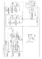
図3は、サーボモータ25の動作を制御する制御装置としてのサーボアンプ27の機能的構成を示すブロック図である。
【0042】
図3において、一点鎖線内の機能ブロックが、通常のサーボ制御にプラスされた本発明独特の制御機能部分である。また、電流の+/−の極性の扱いは、正転状態において、アシスト時は「+」、運動中(負荷時)は「−」としており、そうした意味で、負荷算出部の符号に「−」(マイナス)が付けてある。
【0043】
次に、図3を参照して、制御装置としてのサーボアンプ27の制御動作について説明する。通常のサーボアンプ27及びサーボモータ25の使用形態として速度運転モードにて使用する場合、与えられた速度指令はその時点に於けるサーボモータ25の実速度フィードバック値NFBとの差がなくなるよう速度制御部51にて制御される。この速度制御部51により計算された指示値は、サーボモータ25に流す電流指令であるが、サーボアンプ27およびサーボモータ25の最大許容電流を越えて破損することのないよう、電流制限部52により制限を加えられて保護される。また、本発明では、電流制限部52は、本発明装置の使用者に過大な補助力が加わらないように電流指令を制限するように作用する。ちなみに速度制御部51からの電流指令ICMDを制限する判断基準を、サーボアンプ27及びサーボモータ25の保護レベルではなく、使用する人に対するトルク制限として使用することにより、アシスト時のトルクを使用者に応じて調節することができる。
【0044】
電流制限部52のチェックをパスした電流指令ICMDは、電流比較部53で零電流と比較され、ICMD<0であれば、指令電流制御部54で零に制御され、ICMD≧0であれば、そのまま加算部55へ出力され、そこで後述する負荷制御系の出力と加算されて、減算部56へ送られる。
【0045】
減算部56では、加算部55の出力が、サーボモータ25を制御する後述のトランジスタ58の出力電流を検出する電流検出部59からのフィードバック出力により減算されて電流制御部57へ送られる。
【0046】
電流制御部57では、先程の速度と同様に、減算部56の出力に基づいて、その時点に於けるサーボモータ25に流れる実電流値(フィードバックされる電流値)との差がなくなるよう電流制御され、この制御結果に基づいて、サーボモータ25に流す電流をコントロールするトランジスタ58をオン、オフする。トランジスタ58には外部より電源電圧Vpが加えられており、オン時にサーボモータ25に電流を流してサーボモータ25を駆動する。
【0047】
なお、この際、正転時にサーボモータ25に流れる電流の方向(=電流指令の向き)として、停止からアシスト速度までの加速時を「+」とすると、アシスト速度より高い速度からアシスト速度までの減速時は「−」となる。サーボモータ25が逆転すると極性が逆になるが、説明の便宜上、これ以降正転を基準として説明する。
【0048】
今、本発明装置に対しても、通常のサーボアンプと同様の制御のみを行い、アシスト駆動(補助力駆動)しようとした場合、サーボモータ25により回転駆動されるペダル22は、速度指令の速度をとり続けるよう制御されるため、人が速く回わそうとしたり、人の力で回す(=負荷をとりながら運動する)ことができない。
【0049】
また一方、サーボモータ25を負荷として使用する際は、先述の電流方向を基準として考えると、逆向きに流すことにより反力を得ることができる。この場合、先述の速度制御(アシスト制御)がなければ、後述する負荷制御モードに従って指示された負荷トルクがサーボアンプ27の電流指令として入力されればよい。
【0050】
そこで、負荷とアシストとを両立させた制御を実現するために、電流の極性に着目して、図3に示すブロック図のように、それぞれの指令が電流制御部57へ入力される部分を構成することによって可能となる。
【0051】
すなわち、サーボモータ25の実速度を表す実速度フィードバック値NFBがアシスト指令速度NAST以下の状態(NFB≦NAST)であれば、人の足には負荷がかからずにアシスト指令速度NASTに増速する必要があるため、速度制御部51から指示された電流指令ICMDが電流制御部57に入力されるとともに負荷トルク指令値TCMDをキャンセルするようにする。
【0052】
また、サーボモータ25の現在速度(実速度フィードバック値)NFBがアシスト指令速度NASTを越えている状態(NFB>NAST)であれば、人の足に負荷が加わるとともに速度制御系からの制御でアシスト指令速度NASTに下がらないよう速度制御系からの電流指令ICMDをキャンセルする(ICMD=0)とともに、負荷トルク指令値TCMDを電流制御部57に入力する。
【0053】
具体的には、現在速度NFBがアシスト指令速度NAST以下の状態(NFB≦NAST)であれば、速度制御部51から出力される電流指令ICMDの極性は「+」のため電流制御部57にそのまま入力されるが、現在速度NFBがアシスト指令速度NAST以上の状態(NFB>NAST)であれば、速度制御部51から出力される電流指令ICMDの極性は「−」となるため、これが電流制御部57に入らないよう零にする(ICMD=0)。
【0054】
一方、負荷制御系は、現在速度NFBがアシスト指令速度NAST以下の状態(NFB≦NAST)であれば、負荷が加わらないよう負荷トルク指令値TCMDを零にし、現在速度NFBがアシスト指令速度NASTを越える状態(NFB>NAST)であれば、負荷トルク指令値TCMDを出力する。
【0055】
ここで、負荷制御について説明する。負荷制御方法には、図3に示すように、等速度制御モード、定ワット(運動量)制御モード、定トルク制御モードの3種類が一般的に存在する。
【0056】
等速度制御モードは、目標となるペダル回転速度を人の漕ぎ方によらず一定に維持させるモードで、目標速度以下の状態では負荷を加えず軽くすることで加速し易くし、目標速度を少しでも越えるとその力の量に応じて負荷を与え、目標速度に拮抗させる。
【0057】
等速度制御モードの制御方法としては幾つかのものがあるが、本発明では、ペダル22すなわちサーボモータ25の目標速度(指令速度)と現在速度との偏差εを減算部60で求めて、この偏差εに応じて負荷が決まるように、等速制御部61で偏差εに制御ゲイン(GP+GI+GD)を乗じて負荷(トルク指令値)を算出する方法を採用している。ここで、GPは比例ゲイン、GIは積分ゲイン、GDは微分ゲインである。すなわち、負荷トルク指令値TCMDは、
TCMD=−ε(GP+GI+GD)
により求める。この等速度制御モードにおける負荷トルクとペダル回転速度との関係の一例を図4の(C)に示す。この図において、ペダル回転速度が所定回転速度N以下では、負荷トルクは略メカロス分と等しい値に制御され、所定回転速度Nを越えると急峻に増大する。
【0058】
定ワット制御モードは、ペダル22を回す速度によらずワット(運動量)を一定にする負荷制御方法である。物理的にワット(運動量)は、
ワット=速度×トルク×比例定数
の方程式の関係があることより、定ワット制御部63により、ペダル回転速度に反比例して負荷トルクを与える制御を行う。すなわち、上記方程式より、負荷トルク指令値TCMDは、
TCMD=−k*WCMD/NFB
として求められる。ここで、−kは比例定数、WCMDはワット指令値である。一例として、定ワット制御モードにおける負荷トルクとペダル回転速度との関係を図4の(A)に示す。この例では、負荷トルクはペダル回転速度が増大するに従って2次曲線的に減少していき、ペダル回転速度が120rpmに達するとメカロス分に相当する値に減少する。
【0059】
定トルク制御モードは、負荷トルク一定でサーボアンプ27の電流制御に指令を与えればよいが、設定方式をワット(運動量)指示とするために、規定速度NCMDという値を設定し、ワット指示値WCMDを規定速度NCMDで除して負荷トルクを算出する方式をここでは採用している。すなわち、負荷トルク指令値TCMDは、
TCMD=−k*WCMD/NCMD
として求められる。この場合の負荷トルクとペダル回転速度との関係を図4の(B)に示す。
【0060】
また、負荷制御系では、サーボモータ25の実速度フィードバック値NFBを積分部67により積分して求めたペダル位置データにより負荷トルク指令値TCMDを変更すれば、ペダル角度に応じた負荷を得ることができる。
【0061】
このため、定ワット制御部63により得られた負荷トルク指令値TCMDは、第1角度変更部69により変更制御され、また、定トルク制御部65により得られた負荷トルク指令値TCMDは、第2角度変更部71により変更制御される。例えば、使用者のペダル駆動力が最大となるペダル位置(使用者の両脚が揃った状態で、脚に対して90度の位置)では、負荷ゲインを100%にして、使用者のペダル駆動力が最小となるペダル位置(使用者の両脚が揃った状態で、脚に対して0度或いは180度の位置)では、負荷ゲインを0%に設定し、駆動力最大ペダル位置から駆動力最小ペダル位置へは、負荷ゲインが、例えばコサイン曲線に沿って徐々に減少し、一方、駆動力最小ペダル位置から駆動力最大ペダル位置へは、負荷ゲインが、例えばサイン曲線に沿って徐々に増大するように制御する。
【0062】
そして、等速制御部61、第1角度変更部69、第2負荷変更部71の出力TCMDを後述する切替部73により運転モードに応じて切替制御して負荷トルク比較部75に出力し、そこで負荷トルク指令値TCMDが零以下か判定する。負荷トルク指令値TCMDが零より大きければ(TCMD>0)、負荷トルク制御部77で負荷トルク指令値TCMDを零にし(TCMD=0)、一方、負荷トルク指令値TCMDが零以下であれば(TCMD≦0)、負荷トルク指令値TCMDをそのまま速度比較部79へ出力する。速度比較部79では、速度フィードバック値NFBをアシスト速度指令値NASTと比較して、NFB≦NASTであれば、負荷トルク制御部81で負荷トルク指令値TCMDを零にし、一方NFB>NASTであれば、そのまま、負荷トルク指令値TCMDを加算部55へ出力する。
【0063】
加算部55では負荷制御系の出力である負荷トルク指令値TCMDとアシスト制御系の出力である電流指令値ICMDとを加算して、減算部56へ出力する。減算部56では、加算部55の出力(TCMD+ICMD)をトランジスタ58からフィードバックされた出力(サーボモータ25への供給電流)で減算して、電流制御部57へ出力する。電流制御部57は、減算部56からの出力に応じてトランジスタ58をオンオフ制御して、サーボモータ25の電流を制御する。
【0064】
以上から明なように、本発明によれば、サーボモータ25を運動の補助力装置として使用する際に、電流制限部52等により補助トルクを調節および制限することができるので、運動する個人の許容レベル毎に補助トルクを調整し、明らかに危険な力を制限することにより、絶対的および個人に合わせて安全性を確保することができる。また、補助トルクを弱めに調節すれば、ある程度自分で力を出さないと動作しないため、完全に機械に頼るのではなく、運動を助長することができる。
【0065】
さらに、サーボモータ25を運動の補助力装置として使用する際に、運動療法装置の機械摩擦が、これを使用する運動者の力を上回る位置または角度範囲、および運動者の身体的能力によりペダリングできない位置または角度範囲を基準として補助力を効かせることができるので、ペダル一回転内の全ての領域で機械摩擦の補償をするのではなく、人がペダルを廻せない範囲のみを補償することにより、機械摩擦の重さに対して運動者の力が不足している区間および片麻痺などの身体的能力低下等により、ペダリングできない区間があるために連続的にペダリングできない運動者に対し、連続的に運動できるようにすることが可能である。
【0066】
また、サーボモータ25の回転停止時や低速回転時に、サーボモータ25に電流を供給することにより、回転停止時や低速回転時の負荷を得ることができるので、従来の機器のように、回転停止時や低速回転時の十分な発電エネルギーを得ることができない状態でも負荷を発生することができる。従って、老人や疾病患者など運動者の身体的能力により、低速でしか運動できない者の使用に対して、有効な負荷制御範囲を得て使用させることが可能であり、また、健常者に対してもこれまで実施できなかった速度範囲での運動を開拓することができる。
【0067】
さらにまた、サーボアンプ27を使用することでサーボモータ25の定格電流よりも大きな電流を供給することができるので、定格負荷よりも大きな負荷を得られる。つまり、発電エネルギーに依存する従来方式では、最大でも定格負荷までしか取ることができないのに対し、本発明では、同一アクチュエータ(サーボモータ25)にてそれ以上の負荷を取ることができる。このため、アクチュエータとして定格負荷の小さなサーボモータ25が使用できるため、装置全体を一層小型化することができる。
【0068】
さらに、本発明によれば、運動を行なう際に可動部分としてのペダル22の位置あるいは角度を検出する検出部としての速度センサ25aを備え、これからの検出位置あるいは角度情報に基づいて、第1および第2負荷変更部69、71により運動者に与える負荷量を調節することができるので、従来機器では、1回転内の位置に応じて負荷を変えることができなかったのに対し、本発明では、これを可能とすることができる。従って、ペダル22の位置(角度)によって、これを回転させるのに活躍する筋肉が異なるが、角度毎に負荷を変えることにより、鍛えたい筋肉毎に負荷調節することが可能となり、効果的なトレーニングが可能となる。また、片麻痺などの身体的能力低下の問題により、ペダリングできない区間がある運動者に対しても、廻すことができる範囲とそうでない範囲とに区別した負荷設定をすることで、連続的な運動が可能になる。
【0069】
実施の形態2.
図5は、使用者個人の許容負荷TPAS等に応じて定ワット制御部63の出力を調整する負荷トルク調整部83を設けた例を示している。負荷トルク調整部83は、実施の形態1の図3において定ワット制御部63と第1角度変更部69との間、或いは第1角度変更部69と切替部73との間に挿入され、定ワット制御部63の出力或いは第1角度変更部69の出力を調整するものである。すなわち、サーボモータ25の現在速度(実速度フィードバック値NFB)により、負荷トルクの割合を調節、決定するものである。この調節方法の一例としては、第1の所定速度NLOWの場合には、負荷トルク=0つまり負荷ワット=0として、停止時からの踏み始めで漕ぎにくくないようにする。また、第1の所定速度NLOWよりも大きな第2の所定速度NHIGHまでの間についても、負荷をかけつつも踏みやすさを得るため本来加えるべき力の割合を徐々に増加させる。
【0070】
図6は負荷トルク調整部83の動作を示すもので、図6の(A)は負荷トルク調整部83の動作内容を示すフローチャートであり、(B)はペダル回転速度と負荷率との関係を示す特性図であり、破線(a)は定ワット制御部63の出力、一点鎖線(b)は定ワット制御部63の出力TCMDに乗算される負荷率、実線(c)は負荷トルク調整部83の出力をそれぞれ表しており、(C)は負荷トルクが個人許容負荷TPASを越えないように調整された状態を表す特性図である。
【0071】
次に、この負荷トルク調整部83の動作について図6を参照して説明する。
まず、サーボモータ25の現在速度(実速度フィードバック値NFB)が第1の所定回転速度NLOWより小さいかを判定し(ステップS1)、「YES」であれば定ワット制御部63の出力TCMDに負荷率「0」を掛けて零に設定して出力し(TCMD=0)(ステップS2)、「NO」であれば、次いでNFBが第1の所定回転速度NLOWより大きな第2の所定回転速度NHIGHより大きいかを判定し(ステップS4)、「NO」であれば、TCMDを次式により調整する。
【0072】
TCMD=TCMD×(NFB−NLOW)/(NHIGH−HLOW)
ここで、(NFB−NLOW)/(NHIGH−HLOW)は負荷率である。例えば負荷率は、図6(B)に一点鎖線(b)で示すように、回転速度が零からNLOW迄は0%、NLOWからNHIGHの間では一定の勾配で増大し、NHIGH以上では100%に設定される。この結果、負荷率を掛けて調整された出力TCMDは、図6(B)に実線(c)で示すような曲線を描く。
【0073】
ステップS3で「YES」であれば、ステップS4をスキップして、或いはステップS4に続いて、ステップS5で、TCMDがTPASより大きいか(TCMD>TPAS)を判定し、図6(C)に示すように、「NO」であればTCMDをそのまま出力し(ステップS6)、「YES」であれば、TCMDをTPASでクリップして(TCMD=TPAS)出力する(ステップS7)。
【0074】
また、サーボモータ25を負荷装置として使用するの際に、負荷トルク調整部83により運動時の速度を調節および制限することができるので、運動時に運動者にとって過度の速度でペダリングすることを防ぐことができる。従って、運動者が過度の速度を出すことがなくなるため、足の筋を痛める等、急激な運動による疾病を予防ことが可能である。
【0075】
さらに、サーボモータ25を運動の補助力装置として使用する際に、駆動部の速度を調節および制限することができるので、運動の速度と相関関係を持った速度を設定するとともに、明らかに危険な速度を出なくすることにより、絶対的および個人に合わせた安全性の確保が可能となる。また、補助トルクが発生する速度を運動させたいペダリング速度より低く設定すると、疲労や身体的能力によりペダリングしない区間のみ補助力を有効とし、自分で運動できる区間は自力で運動できるようにすることができる。
【0076】
ところで、運動時のペダリング速度を一定にするためには、ペダル反力(負荷)を加えられた力に拮抗させて対抗することが必要であるが、本発明によれば、サーボモータ25を負荷装置として使用する際に、負荷トルク調整部83により運動時の負荷トルクを調節及び制限することができるので、この制御の力の限界を制限することにより、明らかに危険な力を発生させないようにして、運動者に危険が及ぶのを未然に防止するとともに、個人レベルに合わせた安全性を確保することができる。
【0077】
以上の説明では、負荷トルク調整部83を定ワット制御部63と第1角度変更部69との間に設けたものとして説明したが、負荷トルク調整部83を第1角度変更部69と切替部73との間に設けてもよく、この場合にも、負荷トルク調整部83は第1角度変更部69の出力に対して略同様に作用する。
【0078】
実施の形態3.
図7は本発明の実施の形態3に係る運動療法装置の動作を示すブロック図である。この実施の形態3では、負荷制御には直接関与しないが、現在の運動状態を判別して異常な速度(過速度)時には、使用者に警報(アラーム)するようにした処理を、実施の形態1で説明した処理とは別にサーボアンプ27内に設けたものである。具体的には、図7のフローチャートに示すように、ペダル回転速度が所定の制限速度より速いか否かを判定し(ステップS11)、「YES」の場合には、使用者に「過速度」を警告する過速度アラーム処理を行い(ステップS12)、「NO」の場合には、警報を発しないで現状の制御を許容する(ステップS13)。過速度アラーム処理としては、過速度アラームとして運動者にその旨のメッセージを表示して、人の運動制御の下にペダリングの速度を落とす方法や、過速度時に負荷を徐々に重くしていき、負荷が重くなることにより、速い速度で漕げなくする方法等により、運動時の速度を調節、制限することが考えられる。
【0079】
また、この過速度アラーム処理としては、運動者が設定した速度よりも速い速度で運動しようとしても設定速度を保つように負荷を調節するようにしてもよい。
【0080】
実施の形態4.
図8は本発明の実施の形態4に係る運動療法装置の動作を示すブロック図で、この実施の形態4では、基本的には等速度制御モード以外の運動モード使用時に、過速度となった場合には等速度制御モードへ移行する機能を設けたものであり、例えばこの機能を実施の形態1の切替部73により実行させることにより、各制御モードを切り替えるようにしてもよい。
【0081】
具体的には、図8のフローチャートに示すように、先ず、サーボアンプ27への入力(目標速度、指令ワット、規定速度)から等速度制御モードか否か判定し(ステップS21)、目標速度の入力があれば(「YES」の場合)等速度制御モードを実行し、目標速度の入力が無ければ(「NO」の場合)、次いでサーボアンプ27への入力(目標速度、指令ワット、規定速度)から定ワット制御モードか否かを判定し(ステップS23)、指令ワットの入力があれば(「YES」の場合)、次にサーボモータ25の現在速度が設定速度より速いか否か判定し(ステップS24)、「YES」であれば等速度制御モードを実行し(ステップS22)、「NO」であれば定ワット制御モードを実行する(ステップS25)。また、ステップS23で指令ワットの入力が無ければ(「NO」の場合)、サーボモータ25の現在速度が設定速度より速いか否か判定し(ステップS26)、「YES」であれば等速度制御モードを実行し(ステップS22)、「NO」であれば定トルク制御モードを実行する(ステップS27)。
【0082】
尚、ステップS25の定ワット制御及びステップS27の定トルク制御は一例を示したものであり、他の制御モードを設ければ、それを実行するようにしてもよい。
【0083】
実施の形態5.
図9は本発明の実施の形態5に係る運動療法装置の動作を示すブロック図で、この実施の形態5では、図3の実施の形態1のサーボアンプ27の等速制御部61の各制御パラメータ(比例ゲインGP、積分ゲインGI、微分ゲインGD)を調整する設定入力部62を設け、この設定入力部62の入力操作により等速制御部61の各制御パラメータを変更制御し得るようにしたものであり、これにより負荷トルクを制御して、装置の応答性を調整することができる。
【0084】
すなわち、図9に示すように、等速制御部61は、目標速度とサーボモータ25の現在速度(実速度フィードバック値NFB)の偏差εに比例ゲインGPを乗算し、また偏差εを積分(累積)したものに積分ゲインGIを乗算し、更に偏差εを微分したものに微分ゲインGDを乗算して、それらを加算して負荷トルク値として出力するが、設定入力部62に「かたい」、「ふつう」、「やわらかい」等の指令を操作ボタン、キーボード、マウス等の入力手段により入力することにより、比例ゲインGP、積分ゲインGI、微分ゲインGDを変更して、負荷トルクを調節することにより装置の応答性を調整することができる。例えば、「かたい」を入力することにより、各ゲインを大きくし負荷トルクを急激に変化させて応答性を良くしたり、「やわらかい」を入力して各ゲインを小さくすることにより負荷トルクをゆっくり変化させて装置の応答性を緩やかに変えることができる。
【0085】
また、設定入力部62のこのような動作は、「かたい」、「ふつう」、「やわらかい」等の所定の入力に対応する比例ゲインGP、積分ゲインGI、微分ゲインGDの変更を予めテーブル等にしておいたり、パターン化して記憶しておくことにより行うことができる。
【0086】
また、このような制御パラメータの変更は、患者等の使用者各人に合わせて予め設定しておき、操作ボタン、キーボード、マウス等の入力手段により「患者1設定」、「患者2設定」等を入力することを行うようにしてもよい
【0087】
実施の形態6.
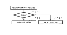
図10は本発明の実施の形態6に係る運動療法装置の動作を示すブロック図で、この実施の形態6では、負荷制御には直接関与しないが、現在の電流状態を判別して異常な電流(過電流度)時には、使用者に警報(アラーム)するようにした処理を、実施の形態1で説明した処理とは別にサーボアンプ27内に設けたものである。具体的には、図10のフローチャートに示すように、サーボモータ25への供給電流(トランジスタ58の出力)が所定の制限電流より大きいか否かを判定して(ステップS31)、「YES」の場合には、使用者に「過電流」を警告する過電流アラーム処理を行い(ステップS32)、「NO」の場合には、警報を発しないで現状の制御を許容する(ステップS33)。
【0088】
過電流アラーム処理の具体例としては、サーボモータ25への供給電流(トランジスタ58の出力)が所定の制限電流より大きい場合に、例えば、電流制限部57(図3参照)により、トランジスタ58への供給電流を減少させたりオフにして、サーボモータ25の動作を制御する。
【0089】
図11は、サーボアンプ27内に使用されているトランジスタ58等の半導体電子部品およびサーボモータ25の耐熱特性を示すもので、耐熱限界付近における電流と時間との関係を表している。この図において、実線は半導体電子部品の耐熱特性(加熱保護協調カーブ)で、点線はサーボモータ25の耐熱特性(加熱保護協調カーブ)を示している。この図から明らかなように、過度の瞬時電流が流れるような場合には、サーボモータ25の方が半導体電子部品よりも耐熱性に優れるが、過度の連続負荷による温度上昇(電流が長時間継続して流れている)ような場合には、逆に半導体電子部品の方が耐熱性に優れている。
【0090】
従って、このような耐熱特性を考慮して、サーボモータ25へ供給する電流を制御することにより、運動時に機器にとって過度の瞬時電流が流れることを防止して過度の瞬時過電流による半導体電子部品等の焼損や損傷を未然に防いだり、或いは運動時に機器にとって過度の連続負荷(オーバロード)による温度上昇を防止して、過負荷によるサーボモータ25等の焼損や損傷を防ぐことができる。
【0091】
実施の形態7.
図12は本発明の実施の形態6に係る運動療法装置の動作を示すブロック図で、この実施の形態7では、当該運動療法装置の使い心地を、ばね定数、粘性係数、慣性からなる機械パラメータにより設定、調節することができるようにしたものである。すなわち、負荷トルクをばね力、粘性力、慣性力に分解して捉えて、これらの合力として表すことにより、負荷トルクをばね定数K、粘性係数B、慣性係数Mよりなる機械パラメータにより設定、調節し得るようにしたものである。
【0092】
図12において、制御装置としてのサーボアンプ27は、基準位置(停止位置)と速度センサ出力(サーボモータ25の実速度フィードバック値NFB)を積分して得た現在位置(位置FB)との差分より位置変位を検出し、その位置変位にばね定数Kを乗算し、また、速度センサ出力(速度FB)に粘性係数Bを乗算し、更に、速度センサ出力(速度FB)を微分した値に慣性係数Mを乗算して、これらの演算値を加算して負荷トルクとして出力するパラメータ演算制御部を有する。
【0093】
このように、パラメータ演算制御部は、サーボモータ25の現在位置の基準位置に対する偏差に基づいて負荷トルクを演算するものであり、パラメータK、B、Mを変更することにより、出力される負荷トルクを調節することができ、これにより運動療法装置の使い心地を調節することができる。
【0094】
実施の形態8.
図13は本発明の実施の形態8に係る運動療法装置の構成を示すブロック図である。この実施の形態8は、上記実施の形態7のパラメータ演算制御部を組み込むことにより、運動者個人が持つ、下肢の等価機械パラメータを、ばね定数K、粘性係数B、慣性係数Mの各パラメータとして計測することができるようにしたものである。
【0095】
図13において、符号21乃至27は上記実施の形態1と同様の構成要素を表している。この実施の形態8の制御装置は、サーボモータ25の動作を制御するサーボアンプ100と、上記各パラメータを計測するためのパラメータ計測部121とを有する。
【0096】
サーボアンプ100は、外部より位置指令を入力される位置指令部101と、その位置指令部101の出力と後述する偏差累積部117の出力との偏差を求める減算部103と、減算部103の出力に基づいてサーボモータ25の位置を制御する位置制御部105と、位置制御部105の出力と速度センサ25aの出力との偏差を求める減算部107と、減算部107の出力に基づいてサーボモータ25の速度を制御するための電流値を出力する速度制御部109と、速度制御部109の出力と後述する電流検出部115の出力との偏差を求める減算部111と、減算部111の出力に基づいてサーボモータ25への供給電流を制御する電流制御部113と、電流制御部113からサーボモータ25へ供給される電流を検出する電流検出部115と、速度センサ25aの出力を累積(積分)してサーボモータ25の回転位置を求める偏差累積部117とを含む。
【0097】
また、パラメータ計測部121は、位置指令部101の出力と偏差累積部117の出力との偏差を求める減算部123と、減算部123の出力に基づいてサーボモータ25の位置変位量を求める位置変位部125と、速度センサ25aの出力を微分する微分部127と、位置変位部125の出力にばね定数Kを乗算し、速度センサ25aの出力に粘性係数Bを乗算し、微分部127の出力に慣性係数Mを乗算するゲイン乗算部129と、ゲイン乗算部129の各出力を加え合わせる加算部131と、加算部131の出力と速度センサ25aの出力とを比較してその偏差を出力する比較部133と、比較部133の出力が零になる迄各パラメータ(ゲインK、B、M)を変更調節するゲイン調整部135とを含む。
【0098】
サーボアンプ100は通常の位置ループ制御のサーボアンプとして制御されるもので、位置指令部101に与えられる固定パターンによる位置変動指令により作動される。その際の、サーボモータ25の位置、速度、電流の各フィードバックを測定して記憶し、運動結果の電流フィードバックと機械モデルのゲインK、B、Mの値を変えて得られる出力ができるだけ一致するK、B、Mの値を最小2乗法などにより計算する。得られたK、B、Mの値を測定値として扱う。
【0099】
尚、この実施の形態8の説明では、負荷トルクを制御する必要がないため、負荷制御系は省略されているが、図3に示した実施の形態1と同様の負荷制御系をサーボアンプ100に追加してもよく、このようにすれば負荷トルクの制御を行うことができる共に、負荷制御系に対する制御入力を無し(零)にして、サーボアンプ100とパラメータ計測部121を作動させれば、上述したように、運動者個人の下肢の等価機械パラメータを、ばね定数K、粘性係数B、慣性係数Mの各パラメータとして計測することができる。
【0100】
【発明の効果】
この発明による運動療法装置は、人力により駆動しうる駆動部と、前記駆動部に一方向クラッチを使用することなく直接動力が伝達される動力伝達機構を介して接続されるアクチュエーターと、このアクチュエーターの制御を行う制御装置であって、前記アクチュエーターを前記駆動部に対して負荷装置として作動させると共に同一アクチュエーターを使用して人力による前記駆動部の運動に補助力を付与する補助力装置として作動させるよう前記アクチュエーターを人力により駆動しうる前記駆動部若しくはその人力により駆動された前記アクチュエーターの状態を判別し制御する制御装置とを備えるので、従来のように、負荷用モータ(発電機)と補助力用モータの2つのアクチュエーターを必要とすることなく、唯1個のアクチュエーターにより負荷用モータとアシスト用モータとを兼用することができ、装置全体の構成を簡素化できる上、小型化、低コスト化が可能であるという効果を奏する。
【0101】
また、本発明によれば、アクチュエーターを運動の補助力装置として使用する際に、補助力のトルクを調節および制限することができるので、運動する個人の許容レベル毎に補助トルクを調整し、明らかに危険な力を制限することにより、絶対的および個人に合わせた安全性の確保が可能である。また、補助トルクを弱めに調節すれば、ある程度自分で力を出さないと動作しないため、完全に機械に頼るのではなく、運動を助長することが可能である。
【0102】
さらに、本発明によれば、アクチュエーターを運動の補助力装置として使用する際に、運動療法装置の機械摩擦が、これを使用する運動者の力を上回る位置または角度範囲、および運動者の身体的能力によりペダリングできない位置または角度範囲を基準として補助力を効かせることができるので、ペダル一回転内の全ての領域で機械摩擦の補償をするのではなく、人がペダルを廻せない範囲のみを補償することにより、機械摩擦の重さに対して運動者の力が不足している区間および片麻痺などの身体的能力低下等により、ペダリングできない区間があるために連続的にペダリングできない運動者に対し、連続的に運動できるようにすることが可能である。
【0103】
さらにまた、本発明によれば、アクチュエーターを負荷装置として使用するの際に、運動時の速度を調節および制限することができるので、運動時に運動者にとって過度の速度でペダリングすることを防ぐことができる。従って、運動者が過度の速度を出すことがなくなるため、足の筋を痛める等、急激な運動による疾病を予防ことが可能である。
【0104】
また、本発明によれば、アクチュエーターを運動の補助力装置として使用する際に、駆動部の速度を調節および制限することができるので、運動の速度と相関関係を持った速度を設定するとともに、明らかに危険な速度を出なくすることにより、絶対的および個人に合わせた安全性の確保が可能となる。また、補助トルクが発生する速度を運動させたいペダリング速度より低く設定すると、疲労や身体的能力によりペダリングしない区間のみ補助力を有効とし、自分で運動できる区間は自力で運動できるようにすることが可能である。
【0105】
さらに、運動時のペダリング速度を一定にするためには、ペダル反力(負荷)を加えられた力に拮抗させて対抗することが必要であるが、本発明によれば、アクチュエーターを負荷装置として使用する際に、運動時の負荷トルクを調節及び制限することができるので、装置の応答性を高める程、運動者はより高い瞬発力を発生する必要があるが、この制御の力の限界を制限することにより、明らかに危険な力を発生させないようにして、運動者に危険が及ぶのを未然に防止するとともに、個人レベルに合わせた安全性を確保することが可能である。
【0106】
さらにまた、本発明によれば、アクチュエーターの回転停止時や低速回転時に、アクチュエーターに電流を供給することにより、回転停止時や低速回転時の負荷を得ることができるので、従来の機器のように、アクチュエータを負荷として機能させるために発電エネルギーを消費する必要はなく、目的とする負荷に対して十分な発電エネルギーを得ることができない状態でも負荷を発生することができる。従って、老人や疾病患者など運動者の身体的能力により、低速でしか運動できない者の使用に対して、有効な負荷制御範囲を得て使用させることが可能であり、また、健常者に対してもこれまで実施できなかった速度範囲での運動を開拓することができる。
【0107】
また、本発明によれば、アクチュエーターの定格電流よりも大きな電流を供給することにより、定格負荷よりも大きな負荷を得ることができるので、発電エネルギーに依存する従来方式では、最大でも定格負荷までしか取ることができないのに対し、本発明では、同一アクチュエータにてそれ以上の負荷を取ることができる。このため、アクチュエータとして定格負荷の小さなモータが使用できるため、装置を一層小型化することが可能である。
【0108】
さらに、本発明によれば、運動を行なう際に可動部分の位置あるいは角度を検出する機構を備え、これからの検出位置あるいは角度情報に基づき運動者に与える負荷量を調節することができるので、従来機器では、1回転内の位置に応じて負荷を変えることができなかったのに対し、本発明では、これを可能とすることができる。従って、ペダルの位置(角度)によって、これを回転させるのに活躍する筋肉が異なるが、角度毎に負荷を変えることにより、鍛えたい筋肉毎に負荷調節することが可能となり、効果的なトレーニングが可能となる。また、片麻痺などの身体的能力低下の問題により、ペダリングできない区間がある運動者に対しても、廻すことができる範囲とそうでない範囲とに区別した負荷設定をすることで、連続的な運動が可能になる。
【0109】
さらにまた、本発明によれば、運動を行なう際に可動部分の位置あるいは角度の基準点を電源遮断時もバックアップすることができるので、角度による負荷変更を行うなどの場合、一回転内のどこかに必ず基準点を設ける必然性があるが、電源をオフしても前回決定した基準点を記憶し、再使用することができる。従って、電源再投入後に基準点再セットを不要とすることができるため、角度の基準点を、電源オンする度に設定する煩わしさをなくすることができると共に、前回の基準を再使用することで、再現性を確保することが可能である。
【0110】
また、本発明によれば、アクチュエーターに流れる電流の方向を逆転することにより正転と逆転の両方で使用することができるので、従来では、ワンウェイクラッチ等により補助力駆動と負荷運動の両立を実現化していたため、逆回転ではワンウェイクラッチが機能せず、使用不可であったのを、本発明では、これを可能とするのができる。従って、逆回転運動にも使用することができ、これにより、運動形態として使用する筋肉が異なるため、正転とは別の筋肉のトレーニングが可能になる。
【0111】
さらに、定ワット負荷制御では、ペダリングの速度が遅くなるほど負荷トルクを大きくする必要があるため、ペダリングの速度が遅くなるほど負荷トルクを大きくする必要があり、この制御を正しく行おうとすれば、微速時になるほど、より大きなトルク(力)が必要となり、筋力限界により近くなるため、漕ぎにくい状況となるが、本発明では、定ワットでの負荷制御を行う際に、低速域にて高くなるべき負荷トルクを低く抑えることにより、運動しやすくすることができ、漕ぎやすくなる効果がある。
【0112】
さらにまた、本発明によれば、定ワットでの負荷制御を行う際に、運動者の出せる力を考慮し、個人毎に低速域にて高くなるべき負荷トルクを低く抑えるよう調節することができるので、筋力限界の個人差を解消し、個人毎に漕ぎやすい設定を得ることができる。従って、運動者の個人筋力レベルに合わせて設定できるため、一般健常人から低体力者までさまざまな人にとって、漕ぎやすさを提供することができる。
【0113】
また、本発明によれば、速度と負荷の調整手段として、設定した速度よりも速い速度で運動しようとしても設定速度を保つように負荷を調節することができるので、運動時のペダリング速度を一定にさせて、運動条件を均一に規定することができる。また、過度の速度を出すことがなくなるので、足の筋を痛める等、急激な運動による疾病を予防することが可能である。
【0114】
さらに、負荷制御を行うためには、目標速度と現在速度との偏差に応じて出力トルクを変える制御が必要であるが、その応答性を一義的にしか決められない場合、調整しにくくなるが、本発明によれば、速度と負荷の調整手段として、負荷制御の制御パラメータを有し、この制御パラメータにより応答性を調節、決定することができるので、簡単に応答性を変更することが可能である。
【0115】
さらにまた、上述した応答性は、人の運動に対しては踏み心地として評価されるものであるが、本発明によれば、運動する際の当該運動療法装置の使い心地を、前記負荷制御の制御パラメータを変えることにより設定することができるので、応答性を単なる数値ではなく、人の感覚として設定することができる。従って、数値の意味が判らない人でも、設定変更が可能となり、調節が行い易い。
【0116】
また、運動する運動者毎に前記負荷制御の制御パラメータを変えて設定することができるので、個人毎の運動能力や筋力などによって異なる、踏み心地としての応答性の最適値を個人毎に合わせることができる。従って、一般健常者の漕ぎ易さに合わせると、低体力者にとっては漕ぎ難いものとなるが、個人毎の運動能力や筋力などに合わせることができるので、低体力者でも漕ぎやすい機器を提供することができる。
【0117】
さらに、本発明によれば、運動を行なう際に可動部分の速度を検出する速度検出部を備え、この速度検出部の検出速度情報に基づき、前記可動部分が機械的限界あるいは電気的限界を越えて動かされるのを防止するための過速度保護機能を有するので、運動時に機器にとって過度の速度でペダリングすることを防止することができ、機器を過度の速度による損傷から防ぐことが可能である。
【0118】
さらにまた、本発明によれば、前記アクチュエーターに流れる電流を検出する電流検出部を備え、この電流検出部の検出電流情報に基づき、前記制御装置を焼損させる過電流を防止するための過電流保護機能を有するので、運動時に機器にとって過度の瞬時電流が流れることを防止することができ、機器を過度の瞬時過電流による損傷から防ぐことが可能である。
【0119】
また、本発明によれば、前記アクチュエーターに流れる電流を検出する電流検出部を備え、この電流検出部の検出電流情報に基づき、前記アクチュエーターの過大熱量による焼損を防止するための過負荷保護機能を有するので、運動時に機器にとって過度の連続負荷による温度上昇を防止することができ、機器を過度の負荷(オーバーロード)による損傷から防ぐことが可能である。
【0120】
さらに、本発明によれば、当該運動療法装置の使い心地を、ばね定数、粘性係数、慣性からなる機械パラメータにより設定、調節することができるので、運動時の踏み心地となる応答性を機械モデルとして捉え制御することにより、機械モデルのパラメータとして扱えるため、物理的意味が認識しやすくなる。
【0121】
また、本発明によれば、運動者個人が持つ、下肢の等価機械パラメータを、ばね定数、粘性係数、慣性のパラメータとして計測することができるので、運動者を機械モデルとして捉えることにより、運動者の運動能力を機械モデルとして解析することが可能となり、疾患による機械パラメータの特徴などの相関関係を分析できる可能性がある。
【図面の簡単な説明】
【図1】 本発明の実施の形態1に係る運動療法装置の側面図である。
【図2】 本発明の実施の形態1の要部の斜視図である。
【図3】 本発明の実施の形態1のサーボアンプのブロック図である。
【図4】 本発明の実施の形態1の負荷トルク制御モードを表す特性図である。
【図5】 本発明の実施の形態2のサーボアンプの要部のブロック図である。
【図6】 本発明の実施の形態2の動作を表すフローチャートである。
【図7】 本発明の実施の形態3の動作を表すフローチャートである。
【図8】 本発明の実施の形態4動作を表すフローチャートである。
【図9】 本発明の実施の形態5の動作を表すフローチャートである。
【図10】 本発明の実施の形態6動作を表すフローチャートである。
【図11】 半導体電子部品およびサーボモータ25の耐熱特性を示す特性図である。
【図12】 本発明の実施の形態7動作を表すフローチャートである。
【図13】 本発明の実施の形態8の動作を表すフローチャートである。
【図14】 従来の運動療法装置の概略構成図である。
【符号の説明】
22 ペダル(駆動部)、25 サーボモータ(アクチュエータ)、27 サーボアンプ(制御装置)。[0001]
BACKGROUND OF THE INVENTION
In the present invention, for example, when a physically handicapped person or an elderly person performs exercise therapy, recovery of motor function and maintenance of physical strength can be achieved by assisting the rotational movement of the pedal by passive movement. The present invention relates to an exercise therapy apparatus.
[0002]
[Prior art]
For example, FIG.Hei 11-169484Of a conventional exercise therapy device disclosed in Japanese Patent Publication No.In the figureis there. Figure, 201 is a pulley coupled to the
[0003]
Next, the operation of this conventional exercise therapy apparatus will be described. The rotation of the
[0004]
When changing the load for each of the left and right pedals, the phase angle is shifted by π and a large load and a small load are repeated. In other words, if the load at the place where it is easy to step on with the right lower limb is increased and the load at the place rotated by π from this phase angle (the place where it is easy to step on with the left lower limb) is reduced, The load on the right leg is greater than the load on the lower leg, which is particularly effective when the right leg is to be trained.
[0005]
Since the conventional exercise therapy apparatus is configured as described above, when the
[0006]
In order to solve the above problems,Hei 11-169484In this publication, when a physically handicapped person or an elderly person performs exercise therapy, the pedal rotation movement can be performed smoothly and continuously so that the motor function can be recovered and the physical strength can be maintained. An exercise therapy apparatus has been proposed.
[0007]
In this exercise therapy apparatus, when the rotation speed of the pedal shaft pulley is reduced to a speed set by the assist motor or less, the assist shaft driving mechanism rotates the pedal shaft pulley and the intermediate pulley.
[0008]
Further, in the assist drive mechanism, when the assist motor always rotates around one direction at a preset speed, and the assist motor rotates around one direction by the one-way clutch fixed to the motor shaft of the assist motor, the motor shaft The pulley attached rotatably to the motor shaft is rotated in conjunction with the motor shaft, and when the assist motor rotates in the other direction, the pulley is idled with respect to the motor shaft, and the secondary assist provided on the rotation shaft of the intermediate pulley The pulley is connected to the pulley via the assist belt, and is connected to the pedal shaft pulley via the primary belt by the primary assist pulley provided on the rotation shaft of the intermediate pulley.
[0009]
With such a configuration, when a physically handicapped person or an elderly person performs exercise therapy, the pedal rotation movement can be continuously performed at all angles, and the recovery of the motor function and the maintenance of the physical strength can be achieved.
[0010]
Furthermore, a one-way clutch that releases the rotational movement of the pedal shaft pulley due to the rotation of the load motor is provided, and the load motor is rotated by rotating the assist motor by the load reduction drive mechanism, thereby reducing the load in the low rotation range. be able to.
[0011]
Japanese Patent Application Laid-Open No. 10-179660 uses an AC generator for the motion load generator, and switches the generator to DC brushless servomotor control when the set motion load is less than the mechanical loss. In the case of the set exercise load described above, an exercise load adjustment device configured to control the load on the output of the generator is disclosed. In this exercise load adjusting device, only one generator is used. However, this generator mainly adjusts the exercise load, and compensates for the mechanical loss when the exercise load is less than the mechanical loss. It only works, it does not act to give exercise support force positively to the exerciser.
[0012]
In the above conventional example,Hei 11-169484In the exercise therapy apparatus described in the publication No. 2, since two motors, a load motor that generates a load and an assist motor that generates an auxiliary force (auxiliary force), are used, a power transmission mechanism from each motor to the pedal shaft However, two systems are required, the configuration is complicated, the number of parts is increased, and it is difficult to reduce the size, the weight, and the cost.
[0013]
Further, in the exercise load adjusting device described in Japanese Patent Laid-Open No. 10-179660, since the exercise support force is not positively given to the exerciser, the exerciser is physically disabled or an elderly person who is inferior in physical fitness. In some cases, there is a problem that it is difficult to perform pedal rotation motion smoothly and smoothly when an auxiliary force such as the start of pedaling or low speed rotation is required.
[0014]
The present invention is intended to solve the above-mentioned problems, and when a physically handicapped person or an elderly person performs exercise therapy, the pedal rotation movement is continued smoothly and smoothly according to the physical strength of the athlete. This makes it possible to recover the motor function and maintain the physical strength, and by using only one actuator as a load device and an auxiliary force generator, the configuration is simple, compact, An object of the present invention is to provide an exercise therapy device that is lightweight and can be manufactured at low cost.
[0015]
[Means for Solving the Problems]
The present invention provides a drive unit that can be driven by human power and the drive unit.Power is transmitted directly without using a one-way clutchAn actuator connected via a power transmission mechanism;A control device for controlling the actuator,Actuator-And act as a load device for the drive unitUsing the same actuatorThe actuator is operated as an auxiliary force device that applies an auxiliary force to the movement of the drive unit by human power-TheThe state of the drive unit that can be driven by human power or the actuator that is driven by human power is determined.It is an exercise therapy apparatus provided with the control apparatus which controls.
[0016]
The control device can adjust and limit the torque of the auxiliary force when the actuator is used as an auxiliary force device for movement.
[0017]
Further, when the actuator is used as an auxiliary force device for exercise, the control device has a position or angle range in which the mechanical friction of the drive unit exceeds the force of the exerciser using the actuator, and the physical movement of the exerciser. Auxiliary force can be applied based on a position or angle range that cannot be driven due to the ability.
[0018]
Furthermore, the control device can adjust and limit the speed of the drive unit during exercise when the actuator is used as a load device.
[0019]
In addition, the control device can adjust and limit the speed of the drive unit when the actuator is used as an auxiliary force device for movement.
[0020]
Furthermore, the control device can adjust and limit a load torque during exercise when the actuator is used as a load device.
[0021]
Furthermore, the control device can obtain a load when the rotation is stopped or when the actuator is rotated at a low speed by supplying current to the actuator when the actuator is stopped or rotated at a low speed.
[0022]
The control device can obtain a load larger than the rated load by supplying a current larger than the rated current of the actuator.
[0023]
Furthermore, the exercise therapy device of the present invention includes a detection unit that detects the position or angle of the movable part when performing exercise, and the control device applies a load to the exerciser based on the detection position or angle information of the detection unit. The amount can be adjusted.
[0024]
Furthermore, the control device can back up the reference point of the position or angle of the movable part when the power is shut off during the movement.
[0025]
Furthermore, the controller can be used for both forward rotation and reverse rotation by reversing the direction of the current flowing through the actuator.
[0026]
In addition, when performing load control at a constant watt, the control device can make it easy to exercise by suppressing the load torque that should be high in the low speed range.
[0027]
Furthermore, when performing load control at a constant watt, the control device can be adjusted so that the load torque that should be increased in a low speed range is kept low for each individual in consideration of the force that an athlete can output. is there.
[0028]
Furthermore, the control device can adjust the load so as to maintain the set speed even if it tries to exercise at a speed faster than the speed set by the exerciser as a speed and load adjusting means.
[0029]
Further, the control device has a control parameter for load control as a means for adjusting the speed and load, and the response can be adjusted and determined by the control parameter.
[0030]
Furthermore, the control device can set the comfort of the exercise therapy device when the exerciser exercises by changing the control parameter of the load control.
[0031]
Furthermore, the control device can change and set the control parameter of the load control for each exerciser.
[0032]
The exercise therapy apparatus according to the present invention further includes a speed detection unit that detects a speed of the movable part when performing the movement of the drive unit, and the control device is configured to detect the movable based on the detection speed information of the speed detection unit. It has an overspeed protection function to prevent the part from being moved beyond the mechanical limit or electrical limit.
[0033]
In addition, the exercise therapy device of the present invention includes a current detection unit that detects a current flowing through the actuator, and the control device prevents an overcurrent that causes the control device to burn out based on detection current information of the current detection unit. Therefore, it has an overcurrent protection function.
[0034]
Furthermore, the exercise therapy device of the present invention includes a current detection unit that detects a current flowing through the actuator, and the control device prevents burnout due to an excessive amount of heat of the actuator based on detection current information of the current detection unit. Therefore, it has an overload protection function.
[0035]
Furthermore, the control device can set and adjust the feeling of use of the kinematic therapy device by mechanical parameters including a spring constant, a viscosity coefficient, and inertia.
[0036]
Further, the control device can measure the equivalent mechanical parameters of the lower limbs possessed by the individual athlete as spring parameters, viscosity coefficients, and inertia parameters.
[0037]
DETAILED DESCRIPTION OF THE INVENTION
Embodiments of the present invention will be described below with reference to the accompanying drawings.
[0038]
FIG. 1 is a side view showing a schematic configuration of an exercise therapy apparatus according to the present invention, and FIG. 2 is a perspective view of an essential part thereof.
In FIG. 1,
[0039]
[0040]
The
[0041]
FIG. 3 is a block diagram showing a functional configuration of the
[0042]
In FIG. 3, the functional blocks in the alternate long and short dash line are the control function portions unique to the present invention added to normal servo control. In addition, in the forward rotation state, the +/− polarity of the current is treated as “+” during assist and “−” during exercise (when loaded). In this sense, the sign of the load calculation unit is “−”. "(Minus) is attached.
[0043]
Next, the control operation of the
[0044]
The current command I that passed the
[0045]
In the subtracting unit 56, the output of the adding unit 55 is subtracted by a feedback output from a current detection unit 59 that detects an output current of a transistor 58 (described later) that controls the
[0046]
In the current control unit 57, similarly to the previous speed, based on the output of the subtraction unit 56, current control is performed so as to eliminate the difference from the actual current value (current value fed back) flowing through the
[0047]
At this time, if the acceleration from the stop to the assist speed is “+” as the direction of the current flowing through the
[0048]
Now, when only the same control as that of a normal servo amplifier is performed for the device of the present invention and an assist drive (assisting force drive) is attempted, the pedal 22 rotated by the
[0049]
On the other hand, when the
[0050]
Therefore, in order to realize the control in which the load and the assist are made compatible, paying attention to the polarity of the current, a portion in which each command is input to the current control unit 57 is configured as shown in the block diagram of FIG. This is possible.
[0051]
That is, the actual speed feedback value N representing the actual speed of the servo motor 25.FBAssist command speed NASTThe following states (NFB≦ NAST), There is no load on the human foot and the assist command speed NASTTherefore, the current command I instructed from the speed control unit 51 is required.CMDIs input to the current control unit 57 and the load torque command value TCMDTo cancel.
[0052]
Also, the current speed (actual speed feedback value) N of the
[0053]
Specifically, the current speed NFBAssist command speed NASTThe following states (NFB≦ NAST), The current command I output from the speed control unit 51CMDSince the polarity of “+” is “+”, it is directly input to the current controller 57, but the current speed NFBAssist command speed NASTThe above state (NFB> NAST), The current command I output from the speed control unit 51CMDIs set to zero so that it does not enter the current control unit 57 (I).CMD= 0).
[0054]
On the other hand, the load control system has a current speed NFBAssist command speed NASTThe following states (NFB≦ NAST), The load torque command value T is set so that no load is applied.CMDTo zero and current speed NFBAssist command speed NASTOver N (NFB> NAST), The load torque command value TCMDIs output.
[0055]
Here, load control will be described. As shown in FIG. 3, there are generally three types of load control methods: a constant speed control mode, a constant wattage (momentum) control mode, and a constant torque control mode.
[0056]
The constant speed control mode is a mode that keeps the target pedal rotation speed constant regardless of the person's rowing method.In the state below the target speed, it is easy to accelerate by applying light weight without applying a load. However, if you exceed it, it will give a load according to the amount of force and antagonize the target speed.
[0057]
Although there are several control methods in the constant speed control mode, in the present invention, a deviation ε between the target speed (command speed) of the pedal 22, that is, the
TCMD= -Ε (GP+ GI+ GD)
Ask for. An example of the relationship between the load torque and the pedal rotation speed in the constant speed control mode is shown in FIG. In this figure, when the pedal rotation speed is equal to or lower than the predetermined rotation speed N, the load torque is controlled to a value substantially equal to the mechanical loss, and when the pedal rotation speed N is exceeded, the load torque increases sharply.
[0058]
The constant wattage control mode is a load control method that keeps the watt (momentum) constant regardless of the speed at which the
Watt = Speed x Torque x Proportional constant
Therefore, the constant watt control unit 63 performs control to give a load torque in inverse proportion to the pedal rotation speed. That is, from the above equation, the load torque command value TCMDIs
TCMD= -K * WCMD/ NFB
As required. Where -k is a proportionality constant, WCMDIs the watt command value. As an example, the relationship between the load torque and the pedal rotation speed in the constant wattage control mode is shown in FIG. In this example, the load torque decreases in a quadratic curve as the pedal rotation speed increases, and decreases to a value corresponding to the mechanical loss when the pedal rotation speed reaches 120 rpm.
[0059]
In the constant torque control mode, it is only necessary to give a command to the current control of the
TCMD= -K * WCMD/ NCMD
As required. FIG. 4B shows the relationship between the load torque and the pedal rotation speed in this case.
[0060]
In the load control system, the actual speed feedback value N of the
[0061]
For this reason, the load torque command value T obtained by the constant wattage control unit 63CMDIs controlled by the first
[0062]
And the output T of the constant
[0063]
In the adder 55, a load torque command value T which is an output of the load control system.CMDAnd current command value I which is the output of the assist control systemCMDAnd are output to the subtracting unit 56. In the subtracting unit 56, the output of the adding unit 55 (TCMD+ ICMD) Is subtracted by the output fed back from the transistor 58 (supply current to the servo motor 25) and output to the current control unit 57. The current control unit 57 controls the current of the
[0064]
As is clear from the above, according to the present invention, when the
[0065]
Further, when the
[0066]
Also, when the rotation of the
[0067]
Furthermore, since a current larger than the rated current of the
[0068]
In addition, according to the present invention, the
[0069]
FIG. 5 shows the allowable load T of the individual user.PASThe example which provided the load torque adjustment part 83 which adjusts the output of the constant watt control part 63 according to etc. is shown. The load torque adjusting unit 83 is inserted between the constant watt control unit 63 and the first
[0070]
FIG. 6 shows the operation of the load torque adjusting unit 83, FIG. 6A is a flowchart showing the operation content of the load torque adjusting unit 83, and FIG. 6B shows the relationship between the pedal rotation speed and the load factor. The broken line (a) is the output of the constant watt control unit 63, and the alternate long and short dash line (b) is the output T of the constant watt control unit 63.CMD, The solid line (c) represents the output of the load torque adjusting unit 83, and (C) represents the load allowable torque TPASIt is a characteristic view showing the state adjusted so that it may not be exceeded.
[0071]
Next, the operation of the load torque adjusting unit 83 will be described with reference to FIG.
First, the current speed of the servo motor 25 (actual speed feedback value NFB) Is the first predetermined rotational speed NLOWIt is determined whether it is smaller (step S1), and if “YES”, the output T of the constant wattage control unit 63CMDMultiplied by the load factor “0” to set to zero and output (TCMD= 0) (step S2), if "NO" then NFBIs the first predetermined rotational speed NLOWA larger second predetermined rotational speed NHIGHIt is determined whether it is larger (step S4). If “NO”, TCMDIs adjusted by the following equation.
[0072]
TCMD= TCMD× (NFB-NLOW) / (NHIGH-HLOW)
Where (NFB-NLOW) / (NHIGH-HLOW) Is the load factor. For example, the load factor is calculated from zero to N as indicated by a one-dot chain line (b) in FIG.LOWUntil 0%, NLOWTo NHIGHIncreases with a constant slope between N andHIGHIn the above, it is set to 100%. As a result, the output T adjusted by the load factor is adjusted.CMDDraws a curve as shown by a solid line (c) in FIG.
[0073]
If “YES” in the step S3, the step S4 is skipped or, following the step S4, in a step S5, the TCMDIs TPASIs greater than (TCMD> TPAS), And as shown in FIG.CMDIs output as it is (step S6), and if “YES”, TCMDTPASClip with (TCMD= TPAS) Is output (step S7).
[0074]
Further, when the
[0075]
Further, when the
[0076]
By the way, in order to make the pedaling speed at the time of exercise constant, it is necessary to antagonize and counteract the applied force of the pedal reaction force (load). According to the present invention, the
[0077]
In the above description, the load torque adjusting unit 83 is described as being provided between the constant wattage control unit 63 and the first
[0078]
FIG. 7 is a block diagram showing the operation of the exercise therapy apparatus according to
[0079]
Further, as the overspeed alarm process, the load may be adjusted so that the set speed is maintained even if the exerciser tries to exercise at a speed higher than the speed set by the exerciser.
[0080]
Embodiment 4 FIG.
FIG. 8 is a block diagram showing the operation of the exercise therapy apparatus according to the fourth embodiment of the present invention. In this fourth embodiment, an overspeed is basically achieved when using an exercise mode other than the constant velocity control mode. In some cases, a function of shifting to the constant speed control mode is provided. For example, the control mode may be switched by causing the switching unit 73 of the first embodiment to execute this function.
[0081]
Specifically, as shown in the flowchart of FIG. 8, first, it is determined from the input (target speed, command watt, specified speed) to the
[0082]
Note that the constant wattage control in step S25 and the constant torque control in step S27 are examples, and may be executed if another control mode is provided.
[0083]
FIG. 9 is a block diagram showing the operation of the exercise therapy apparatus according to the fifth embodiment of the present invention. In this fifth embodiment, each control of the constant
[0084]
That is, as shown in FIG. 9, the constant
[0085]
Further, such an operation of the setting
[0086]
In addition, such control parameter changes are set in advance according to each user such as a patient, and “
[0087]
FIG. 10 is a block diagram showing the operation of the exercise therapy apparatus according to the sixth embodiment of the present invention. In this sixth embodiment, an abnormal current is determined by determining the current current state although it is not directly involved in load control. At the time of (overcurrent degree), a process for alarming the user is provided in the
[0088]
As a specific example of the overcurrent alarm process, when the supply current to the servomotor 25 (the output of the transistor 58) is larger than a predetermined limit current, for example, the current limiter 57 (see FIG. 3) The operation of the
[0089]
FIG. 11 shows the heat resistance characteristics of the semiconductor electronic components such as the transistor 58 and the
[0090]
Accordingly, by controlling the current supplied to the
[0091]
FIG. 12 is a block diagram showing the operation of the exercise therapy apparatus according to the sixth embodiment of the present invention. In the seventh embodiment, the usability of the exercise therapy apparatus is represented by mechanical parameters including a spring constant, a viscosity coefficient, and inertia. Can be set and adjusted. That is, the load torque is decomposed into spring force, viscous force, and inertial force, and expressed as the resultant force, so that the load torque is set and adjusted by a mechanical parameter consisting of the spring constant K, viscosity coefficient B, and inertial coefficient M. It is something that can be done.
[0092]
In FIG. 12, a
[0093]
As described above, the parameter calculation control unit calculates the load torque based on the deviation of the current position of the
[0094]
FIG. 13 is a block diagram showing the configuration of the exercise therapy apparatus according to the eighth embodiment of the present invention. In the eighth embodiment, by incorporating the parameter calculation control unit of the seventh embodiment, the equivalent mechanical parameters of the lower limbs possessed by the individual exerciser are used as the spring constant K, the viscosity coefficient B, and the inertia coefficient M, respectively. It can be measured.
[0095]
In FIG. 13,
[0096]
The servo amplifier 100 includes a position command unit 101 to which a position command is input from the outside, a subtraction unit 103 that obtains a deviation between an output of the position command unit 101 and an output of a deviation accumulation unit 117 described later, and an output of the subtraction unit 103. The position control unit 105 that controls the position of the
[0097]
The parameter measurement unit 121 also includes a
[0098]
The servo amplifier 100 is controlled as a normal position loop control servo amplifier, and is operated by a position variation command based on a fixed pattern given to the position command unit 101. At this time, the feedback of the position, speed, and current of the
[0099]
In the description of the eighth embodiment, since it is not necessary to control the load torque, the load control system is omitted. However, the load control system similar to the first embodiment shown in FIG. In this way, it is possible to control the load torque, and when the servo amplifier 100 and the parameter measuring unit 121 are operated with no control input to the load control system (zero). As described above, the equivalent mechanical parameters of the lower limbs of the individual exerciser can be measured as the parameters of the spring constant K, the viscosity coefficient B, and the inertia coefficient M.
[0100]
【The invention's effect】
An exercise therapy apparatus according to the present invention includes a drive unit that can be driven by human power, and the drive unit.Power is transmitted directly without using a one-way clutchAn actuator connected via a power transmission mechanism;A control device for controlling the actuator,Actuator-And act as a load device for the drive unitUsing the same actuatorThe actuator is operated as an auxiliary force device that applies an auxiliary force to the movement of the drive unit by human power-TheThe state of the drive unit that can be driven by human power or the actuator that is driven by human power is determined.Since there is a control device to control, two actuators, a load motor (generator) and an auxiliary force motor, as in the prior art-No need for a single actuator-As a result, the load motor and the assist motor can be used together, and the configuration of the entire apparatus can be simplified, and the size and cost can be reduced.
[0101]
In addition, according to the present invention, when the actuator is used as an exercise assisting force device, the torque of the assisting force can be adjusted and limited. By limiting the dangerous force, absolute and personal safety can be ensured. Moreover, if the auxiliary torque is adjusted to be weak, it will not operate unless a certain amount of force is applied by itself, so that it is possible to promote exercise rather than relying entirely on the machine.
[0102]
Furthermore, according to the present invention, when the actuator is used as an auxiliary force device for exercise, the position or angle range where the mechanical friction of the exercise therapy device exceeds the force of the exerciser using it, and the physical movement of the exerciser Auxiliary force can be applied based on the position or angle range that cannot be pedaled due to ability, so not compensate for mechanical friction in all areas within one rotation of the pedal, but only in the range where the person cannot turn the pedal For athletes who cannot continuously pedal because there are sections where the athlete's force is insufficient with respect to the weight of mechanical friction and where there is a section that cannot be pedaled due to a decrease in physical ability such as hemiplegia. It is possible to be able to exercise continuously.
[0103]
Furthermore, according to the present invention, when the actuator is used as a load device, the speed during exercise can be adjusted and limited, so that it is possible to prevent pedaling at an excessive speed for the exerciser during exercise. it can. Therefore, since an exerciser does not give an excessive speed, it is possible to prevent a disease caused by a sudden exercise such as hurting a leg muscle.
[0104]
In addition, according to the present invention, when the actuator is used as an auxiliary force device for movement, the speed of the drive unit can be adjusted and limited, so that the speed having a correlation with the speed of movement is set, By avoiding apparently dangerous speeds, absolute and personal safety can be ensured. In addition, if the speed at which the assist torque is generated is set lower than the pedaling speed at which you want to exercise, the assist force is effective only in the sections where pedaling is not performed due to fatigue or physical ability, and the sections where you can exercise can be exercised by yourself. Is possible.
[0105]
Furthermore, in order to make the pedaling speed during exercise constant, it is necessary to counteract the force applied to the pedal reaction force (load) against the applied force. According to the present invention, the actuator is used as a load device. In use, the load torque during exercise can be adjusted and limited, so the higher the responsiveness of the device, the more the exerciser needs to generate a higher instantaneous force. By restricting, it is possible to prevent a dangerous force from being clearly generated, to prevent dangers from exercising, and to ensure safety according to the individual level.
[0106]
Furthermore, according to the present invention, when the rotation of the actuator is stopped or when the actuator is rotated at a low speed, a load can be obtained when the rotation is stopped or when the actuator is rotated at a low speed. In addition, it is not necessary to consume the generated energy in order for the actuator to function as a load, and the load can be generated even in a state where sufficient generated energy cannot be obtained for the target load. Therefore, it is possible to obtain and use an effective load control range for the use of those who can exercise only at low speeds due to the physical ability of the exerciser such as the elderly and ill patients. However, it is possible to pioneer the movement in the speed range that could not be carried out until now.
[0107]
Further, according to the present invention, since a load larger than the rated load can be obtained by supplying a current larger than the rated current of the actuator, the conventional method that depends on the power generation energy has only a maximum rated load. On the other hand, in the present invention, it is possible to take more load with the same actuator. For this reason, since a motor with a small rated load can be used as an actuator, the apparatus can be further miniaturized.
[0108]
Furthermore, according to the present invention, a mechanism for detecting the position or angle of the movable part when exercising is provided, and the amount of load applied to the exerciser can be adjusted based on the detected position or angle information from now on. In the device, the load could not be changed according to the position within one rotation, whereas in the present invention, this can be made possible. Therefore, depending on the position (angle) of the pedal, the muscles that are active in rotating it differ, but by changing the load for each angle, it is possible to adjust the load for each muscle you want to train, effective training It becomes possible. In addition, for exercisers who have sections that cannot be pedaled due to problems such as hemiplegia, continuous exercise is possible by distinguishing between the range that can be turned and the range that cannot be turned. Is possible.
[0109]
Furthermore, according to the present invention, the position of the movable part or the reference point of the angle can be backed up even when the power is cut off when performing the exercise. Although it is inevitable to provide a reference point, the reference point determined last time can be stored and reused even when the power is turned off. Therefore, since it is not necessary to reset the reference point after the power is turned on again, the trouble of setting the angle reference point each time the power is turned on can be eliminated, and the previous reference can be reused. Thus, reproducibility can be ensured.
[0110]
In addition, according to the present invention, both the forward rotation and the reverse rotation can be used by reversing the direction of the current flowing in the actuator, so conventionally, both the auxiliary force driving and the load motion are realized by a one-way clutch or the like Since the one-way clutch does not function and cannot be used in reverse rotation, the present invention can make this possible. Therefore, it can also be used for reverse rotation exercise, and this makes it possible to train muscles different from normal rotation because the muscles used as the exercise form are different.
[0111]
Furthermore, in constant wattage load control, it is necessary to increase the load torque as the pedaling speed decreases, so it is necessary to increase the load torque as the pedaling speed decreases. The larger the torque (force) is, the closer it is to the muscular strength limit, which makes it difficult to row. In the present invention, when performing load control at a constant wattage, the load torque that should be increased in the low speed range By keeping the value low, it is easy to exercise and has the effect of making it easier to row.
[0112]
Furthermore, according to the present invention, when performing load control at a constant wattage, it is possible to adjust the load torque that should be increased in a low speed range for each individual to a low level in consideration of the force that an exerciser can output. Therefore, it is possible to eliminate individual differences in the muscular strength limit and to obtain a setting that is easy to row for each individual. Therefore, since it can be set in accordance with the individual muscular strength level of the exerciser, it is possible to provide ease of rowing for various people from general healthy people to low physical strength people.
[0113]
In addition, according to the present invention, as a means for adjusting the speed and load, the load can be adjusted so as to keep the set speed even when trying to exercise at a speed faster than the set speed, so that the pedaling speed during exercise is constant. Thus, the motion condition can be defined uniformly. In addition, since excessive speed is not produced, it is possible to prevent diseases caused by rapid exercise such as hurting leg muscles.
[0114]
Furthermore, in order to perform load control, it is necessary to perform control to change the output torque according to the deviation between the target speed and the current speed, but it is difficult to adjust if the responsiveness can only be determined uniquely. According to the present invention, the control parameter for load control is provided as a means for adjusting the speed and load, and the response can be adjusted and determined by this control parameter, so that the response can be easily changed. It is.
[0115]
Furthermore, although the above-mentioned responsiveness is evaluated as a stepping comfort for a human exercise, according to the present invention, the comfort of the exercise therapy device when exercising is determined by the load control. Since it can be set by changing the control parameter, the responsiveness can be set not as a mere numerical value but as a human sense. Therefore, even a person who does not understand the meaning of the numerical value can change the setting and easily adjust it.
[0116]
In addition, the load control parameters can be set differently for each exercising person, so that the optimum value of the responsiveness as a stepping feeling, which varies depending on the individual's exercising ability, muscle strength, etc., is adjusted for each individual. Can do. Therefore, it is difficult for a low-powered person to row if it matches the ease of rowing for a normal healthy person, but it can be adjusted to the individual's ability to exercise, muscle strength, etc., so that even a low-powered person can easily row. be able to.
[0117]
Furthermore, according to the present invention, a speed detection unit that detects the speed of the movable part when performing an exercise is provided, and based on the detected speed information of the speed detection unit, the movable part exceeds a mechanical limit or an electrical limit. Therefore, it is possible to prevent pedaling at an excessive speed for the apparatus during exercise, and to prevent the apparatus from being damaged by the excessive speed.
[0118]
Furthermore, according to the present invention, there is provided a current detection unit for detecting a current flowing through the actuator, and overcurrent protection for preventing an overcurrent that burns out the control device based on detected current information of the current detection unit. Since it has the function, it is possible to prevent an excessive instantaneous current from flowing to the device during exercise, and it is possible to prevent the device from being damaged by an excessive instantaneous overcurrent.
[0119]
Further, according to the present invention, an overload protection function for preventing a burnout due to an excessive amount of heat of the actuator based on the detected current information of the current detector is provided. Therefore, it is possible to prevent an increase in temperature due to an excessive continuous load for the device during exercise, and it is possible to prevent the device from being damaged by an excessive load (overload).
[0120]
Furthermore, according to the present invention, the comfort of the exercise therapy apparatus can be set and adjusted by the machine parameters including the spring constant, the viscosity coefficient, and the inertia. Since it can be handled as a parameter of a machine model by controlling it as, the physical meaning becomes easy to recognize.
[0121]
In addition, according to the present invention, the equivalent mechanical parameters of the lower limbs possessed by the individual exerciser can be measured as the parameters of the spring constant, the viscosity coefficient, and the inertia. Can be analyzed as a machine model, and there is a possibility that a correlation such as a feature of a machine parameter due to a disease can be analyzed.
[Brief description of the drawings]
FIG. 1 is a side view of an exercise therapy apparatus according to
FIG. 2 is a perspective view of a main part of the first embodiment of the present invention.
FIG. 3 is a block diagram of the servo amplifier according to the first embodiment of the present invention.
FIG. 4 is a characteristic diagram showing a load torque control mode according to the first embodiment of the present invention.
FIG. 5 is a block diagram of a main part of a servo amplifier according to a second embodiment of the present invention.
FIG. 6 is a flowchart showing the operation of the second embodiment of the present invention.
FIG. 7 is a flowchart showing the operation of the third embodiment of the present invention.
FIG. 8 is a flowchart showing the operation of the fourth embodiment of the present invention.
FIG. 9 is a flowchart showing the operation of the fifth embodiment of the present invention.
FIG. 10 is a flowchart showing the operation of the sixth embodiment of the present invention.
11 is a characteristic diagram showing heat resistance characteristics of the semiconductor electronic component and the
FIG. 12 is a flowchart showing the operation of the seventh embodiment of the present invention.
FIG. 13 is a flowchart showing the operation of the eighth embodiment of the present invention.
FIG. 14 is a schematic configuration diagram of a conventional exercise therapy apparatus.
[Explanation of symbols]
22 pedals (drive unit), 25 servo motor (actuator), 27 servo amplifier (control device).
Claims (22)
前記駆動部に一方向クラッチを使用することなく直接動力が伝達される動力伝達機構を介して接続されるアクチュエーターと、
このアクチュエーターの制御を行う制御装置であって、前記アクチュエーターを前記駆動部に対して負荷装置として作動させると共に同一アクチュエーターを使用して人力による前記駆動部の運動に補助力を付与する補助力装置として作動させるよう前記アクチュエーターを人力により駆動しうる前記駆動部若しくはその人力により駆動された前記アクチュエーターの状態を判別し制御する制御装置と、
を備える運動療法装置。A drive unit that can be driven by human power;
An actuator connected via a power transmission mechanism in which power is directly transmitted to the drive unit without using a one-way clutch ;
A control device for controlling the actuator, the auxiliary power device for imparting an auxiliary force to the actuator over the motion of the drive according human power using the same actuator actuates a load device to the drive unit a control device for the actuator over to actuate determine the state of the actuator that is driven by the drive unit or its manpower can be driven by human control as,
An exercise therapy apparatus comprising:
Priority Applications (2)
| Application Number | Priority Date | Filing Date | Title |
|---|---|---|---|
| JP2000125037A JP3929230B2 (en) | 2000-04-26 | 2000-04-26 | Exercise therapy equipment |
| US09/734,881 US6443873B2 (en) | 2000-04-26 | 2000-12-13 | Exercise therapy device |
Applications Claiming Priority (1)
| Application Number | Priority Date | Filing Date | Title |
|---|---|---|---|
| JP2000125037A JP3929230B2 (en) | 2000-04-26 | 2000-04-26 | Exercise therapy equipment |
Publications (3)
| Publication Number | Publication Date |
|---|---|
| JP2001299957A JP2001299957A (en) | 2001-10-30 |
| JP2001299957A5 JP2001299957A5 (en) | 2006-05-25 |
| JP3929230B2 true JP3929230B2 (en) | 2007-06-13 |
Family
ID=18635064
Family Applications (1)
| Application Number | Title | Priority Date | Filing Date |
|---|---|---|---|
| JP2000125037A Expired - Lifetime JP3929230B2 (en) | 2000-04-26 | 2000-04-26 | Exercise therapy equipment |
Country Status (2)
| Country | Link |
|---|---|
| US (1) | US6443873B2 (en) |
| JP (1) | JP3929230B2 (en) |
Families Citing this family (31)
| Publication number | Priority date | Publication date | Assignee | Title |
|---|---|---|---|---|
| US20020198080A1 (en) * | 2001-05-16 | 2002-12-26 | Martin Reck | Training device |
| NL1019984C2 (en) * | 2002-02-18 | 2003-08-19 | Bonte Zwolle B V | Exercise machine with motorised parts, has motor applying counter force to user movable part of machine via coupling effective in only one direction |
| FR2843309B1 (en) * | 2002-08-09 | 2005-12-02 | Distrib Tech De L Ouest | PASSIVE MUSCULATION DEVICE |
| US7182738B2 (en) * | 2003-04-23 | 2007-02-27 | Marctec, Llc | Patient monitoring apparatus and method for orthosis and other devices |
| JP2005027994A (en) * | 2003-07-10 | 2005-02-03 | National Institute Of Advanced Industrial & Technology | Three dimensional therapeutic exercise apparatus by means of isoviscous load |
| JP4199134B2 (en) * | 2004-01-16 | 2008-12-17 | 株式会社コナミスポーツ&ライフ | Training equipment |
| WO2005105222A1 (en) * | 2004-04-27 | 2005-11-10 | Mitsubishi Electric Engineering Company, Limited | Exercise therapy device |
| US7208895B2 (en) * | 2005-06-24 | 2007-04-24 | Emerson Electric Co. | Control systems and methods for permanent magnet rotating machines |
| US7342379B2 (en) | 2005-06-24 | 2008-03-11 | Emerson Electric Co. | Sensorless control systems and methods for permanent magnet rotating machines |
| WO2007076068A2 (en) * | 2005-12-22 | 2007-07-05 | Radow Scott B | Exercise device |
| US7976434B2 (en) * | 2005-12-22 | 2011-07-12 | Scott B. Radow | Exercise device |
| JP5055506B2 (en) * | 2006-03-03 | 2012-10-24 | 国立大学法人長岡技術科学大学 | Training system, training machine control method and control apparatus |
| JP4213722B2 (en) * | 2006-03-07 | 2009-01-21 | 株式会社コナミスポーツ&ライフ | Training equipment |
| US20080161168A1 (en) * | 2006-12-28 | 2008-07-03 | Shih-Wen Hsiao | Power generating structure of an exerciser |
| JP4665945B2 (en) * | 2007-06-26 | 2011-04-06 | パナソニック電工株式会社 | Massage machine |
| US7833135B2 (en) | 2007-06-27 | 2010-11-16 | Scott B. Radow | Stationary exercise equipment |
| JP5308685B2 (en) * | 2008-02-01 | 2013-10-09 | パナソニックヘルスケア株式会社 | Passive exercise equipment |
| JP5260988B2 (en) * | 2008-03-10 | 2013-08-14 | パナソニックヘルスケア株式会社 | Passive exercise equipment and control device |
| US9144709B2 (en) | 2008-08-22 | 2015-09-29 | Alton Reich | Adaptive motor resistance video game exercise apparatus and method of use thereof |
| US20110165997A1 (en) * | 2008-08-22 | 2011-07-07 | Alton Reich | Rotary exercise equipment apparatus and method of use thereof |
| US9272186B2 (en) | 2008-08-22 | 2016-03-01 | Alton Reich | Remote adaptive motor resistance training exercise apparatus and method of use thereof |
| US8264192B2 (en) | 2009-08-10 | 2012-09-11 | Emerson Climate Technologies, Inc. | Controller and method for transitioning between control angles |
| US8378604B2 (en) * | 2010-03-17 | 2013-02-19 | Tai-Her Yang | DC brushless motor drive circuit with current variable-voltage |
| FR2981857B1 (en) * | 2011-10-27 | 2014-11-21 | Eracles Technology | EXERCISE MACHINE |
| US9634593B2 (en) | 2012-04-26 | 2017-04-25 | Emerson Climate Technologies, Inc. | System and method for permanent magnet motor control |
| JP6184353B2 (en) | 2014-03-17 | 2017-08-23 | 三菱電機エンジニアリング株式会社 | Control device and control method for exercise therapy apparatus |
| JP6763541B2 (en) * | 2016-09-07 | 2020-09-30 | 株式会社イープル | Joint exercise training device and joint exercise training method |
| US20210268335A1 (en) * | 2018-08-03 | 2021-09-02 | Mitsubishi Electric Engineering Company, Limited | Exercise therapy device |
| JP7181801B2 (en) * | 2019-01-30 | 2022-12-01 | Cyberdyne株式会社 | Cardiac rehabilitation support device and its control program |
| WO2020172547A1 (en) | 2019-02-21 | 2020-08-27 | Radow Scott B | Exercise equipment with music synchronization |
| CN112472522B (en) * | 2020-12-09 | 2022-07-26 | 中国人民解放军陆军特色医学中心 | Auxiliary recovery equipment for leg sports injury |
Family Cites Families (9)
| Publication number | Priority date | Publication date | Assignee | Title |
|---|---|---|---|---|
| JPS5685366A (en) | 1979-12-13 | 1981-07-11 | Matsushita Electric Ind Co Ltd | Health instrument |
| US4905676A (en) * | 1984-01-06 | 1990-03-06 | Loredan Biomedical, Inc. | Exercise diagnostic system and method |
| US4934694A (en) * | 1985-12-06 | 1990-06-19 | Mcintosh James L | Computer controlled exercise system |
| JPS63130080A (en) | 1986-11-20 | 1988-06-02 | 株式会社 マツシヨウ | Power apparatus of indoor running device |
| US5020795A (en) * | 1989-06-07 | 1991-06-04 | Soma Dynamics Corporation | Physical therapy and exercise apparatus for body limbs |
| US5421798A (en) * | 1993-05-17 | 1995-06-06 | Cedaron Medical, Inc. | Closed chain evaluation and exercise system |
| JPH10179660A (en) | 1996-12-27 | 1998-07-07 | Mitsubishi Electric Corp | Device and method for exercise load regulation |
| JP3308885B2 (en) | 1997-12-15 | 2002-07-29 | 三菱電機株式会社 | Exercise therapy device |
| JP3672724B2 (en) | 1998-03-17 | 2005-07-20 | 三菱電機株式会社 | Exercise therapy device and control method of exercise therapy device |
-
2000
- 2000-04-26 JP JP2000125037A patent/JP3929230B2/en not_active Expired - Lifetime
- 2000-12-13 US US09/734,881 patent/US6443873B2/en not_active Expired - Lifetime
Also Published As
| Publication number | Publication date |
|---|---|
| JP2001299957A (en) | 2001-10-30 |
| US6443873B2 (en) | 2002-09-03 |
| US20010036883A1 (en) | 2001-11-01 |
Similar Documents
| Publication | Publication Date | Title |
|---|---|---|
| JP3929230B2 (en) | Exercise therapy equipment | |
| JP5565762B2 (en) | Training apparatus and training apparatus control method | |
| Boehler et al. | Design, implementation and test results of a robust control method for a powered ankle foot orthosis (AFO) | |
| CA3029593C (en) | Motorized treadmill with motor braking mechanism and methods of operating same | |
| JP6184353B2 (en) | Control device and control method for exercise therapy apparatus | |
| Frey et al. | A novel mechatronic body weight support system | |
| US7211985B2 (en) | Training device | |
| US5462504A (en) | Fitness apparatus with heart rate control system and method of operation | |
| US7410449B2 (en) | Multifunctional exercise treadmill with sensor for activating motor driven tread belt or not in response to force exerted upon the tread belt for additionally exercising either foot muscles or both foot and hand muscles | |
| US20120053014A1 (en) | Apparatus and System for a Resistance Training System | |
| US5618245A (en) | Fitness apparatus with heart rate control system and method of operation | |
| JP4468532B2 (en) | Training equipment | |
| US20180339196A1 (en) | Powered machine and control method | |
| JP4119149B2 (en) | Walking assist device | |
| JP2004329278A (en) | Body lifting implement and walking training machine provided with the same | |
| WO2013018205A1 (en) | Exercise device, motor control device, and motor control method | |
| KR101939581B1 (en) | Gait rehabilitation robot and control method thereof | |
| JP2007307180A (en) | Rehabilitation apparatus | |
| US20230270615A1 (en) | Drive system for exosuits | |
| JPH10113368A (en) | Walk training device | |
| JPH09299412A (en) | Electric vehicle with pedal | |
| JP3406500B2 (en) | Exercise therapy device | |
| WO2005105222A1 (en) | Exercise therapy device | |
| JP4713746B2 (en) | Muscle strength measurement method | |
| JPH10248891A (en) | Rehabilitation device and method |
Legal Events
| Date | Code | Title | Description |
|---|---|---|---|
| A521 | Written amendment |
Free format text: JAPANESE INTERMEDIATE CODE: A523 Effective date: 20060331 |
|
| A621 | Written request for application examination |
Free format text: JAPANESE INTERMEDIATE CODE: A621 Effective date: 20060331 |
|
| RD04 | Notification of resignation of power of attorney |
Free format text: JAPANESE INTERMEDIATE CODE: A7424 Effective date: 20060418 |
|
| A871 | Explanation of circumstances concerning accelerated examination |
Free format text: JAPANESE INTERMEDIATE CODE: A871 Effective date: 20061017 |
|
| A975 | Report on accelerated examination |
Free format text: JAPANESE INTERMEDIATE CODE: A971005 Effective date: 20061109 |
|
| A131 | Notification of reasons for refusal |
Free format text: JAPANESE INTERMEDIATE CODE: A131 Effective date: 20061121 |
|
| A521 | Written amendment |
Free format text: JAPANESE INTERMEDIATE CODE: A523 Effective date: 20070122 |
|
| TRDD | Decision of grant or rejection written | ||
| A01 | Written decision to grant a patent or to grant a registration (utility model) |
Free format text: JAPANESE INTERMEDIATE CODE: A01 Effective date: 20070213 |
|
| A61 | First payment of annual fees (during grant procedure) |
Free format text: JAPANESE INTERMEDIATE CODE: A61 Effective date: 20070306 |
|
| R150 | Certificate of patent or registration of utility model |
Free format text: JAPANESE INTERMEDIATE CODE: R150 Ref document number: 3929230 Country of ref document: JP Free format text: JAPANESE INTERMEDIATE CODE: R150 |
|
| FPAY | Renewal fee payment (event date is renewal date of database) |
Free format text: PAYMENT UNTIL: 20100316 Year of fee payment: 3 |
|
| FPAY | Renewal fee payment (event date is renewal date of database) |
Free format text: PAYMENT UNTIL: 20110316 Year of fee payment: 4 |
|
| R250 | Receipt of annual fees |
Free format text: JAPANESE INTERMEDIATE CODE: R250 |
|
| FPAY | Renewal fee payment (event date is renewal date of database) |
Free format text: PAYMENT UNTIL: 20120316 Year of fee payment: 5 |
|
| R250 | Receipt of annual fees |
Free format text: JAPANESE INTERMEDIATE CODE: R250 |
|
| FPAY | Renewal fee payment (event date is renewal date of database) |
Free format text: PAYMENT UNTIL: 20120316 Year of fee payment: 5 |
|
| FPAY | Renewal fee payment (event date is renewal date of database) |
Free format text: PAYMENT UNTIL: 20130316 Year of fee payment: 6 |
|
| R250 | Receipt of annual fees |
Free format text: JAPANESE INTERMEDIATE CODE: R250 |
|
| FPAY | Renewal fee payment (event date is renewal date of database) |
Free format text: PAYMENT UNTIL: 20130316 Year of fee payment: 6 |
|
| FPAY | Renewal fee payment (event date is renewal date of database) |
Free format text: PAYMENT UNTIL: 20140316 Year of fee payment: 7 |
|
| R250 | Receipt of annual fees |
Free format text: JAPANESE INTERMEDIATE CODE: R250 |
|
| R250 | Receipt of annual fees |
Free format text: JAPANESE INTERMEDIATE CODE: R250 |
|
| R250 | Receipt of annual fees |
Free format text: JAPANESE INTERMEDIATE CODE: R250 |
|
| R250 | Receipt of annual fees |
Free format text: JAPANESE INTERMEDIATE CODE: R250 |
|
| R250 | Receipt of annual fees |
Free format text: JAPANESE INTERMEDIATE CODE: R250 |
|
| R250 | Receipt of annual fees |
Free format text: JAPANESE INTERMEDIATE CODE: R250 |
|
| R250 | Receipt of annual fees |
Free format text: JAPANESE INTERMEDIATE CODE: R250 |
|
| R250 | Receipt of annual fees |
Free format text: JAPANESE INTERMEDIATE CODE: R250 |
|
| EXPY | Cancellation because of completion of term |