WO2013018205A1 - Exercise device, motor control device, and motor control method - Google Patents
Exercise device, motor control device, and motor control method Download PDFInfo
- Publication number
- WO2013018205A1 WO2013018205A1 PCT/JP2011/067738 JP2011067738W WO2013018205A1 WO 2013018205 A1 WO2013018205 A1 WO 2013018205A1 JP 2011067738 W JP2011067738 W JP 2011067738W WO 2013018205 A1 WO2013018205 A1 WO 2013018205A1
- Authority
- WO
- WIPO (PCT)
- Prior art keywords
- unit
- drive
- user
- movable
- motor
- Prior art date
Links
Images


Classifications
-
- A—HUMAN NECESSITIES
- A63—SPORTS; GAMES; AMUSEMENTS
- A63B—APPARATUS FOR PHYSICAL TRAINING, GYMNASTICS, SWIMMING, CLIMBING, OR FENCING; BALL GAMES; TRAINING EQUIPMENT
- A63B21/00—Exercising apparatus for developing or strengthening the muscles or joints of the body by working against a counterforce, with or without measuring devices
- A63B21/005—Exercising apparatus for developing or strengthening the muscles or joints of the body by working against a counterforce, with or without measuring devices using electromagnetic or electric force-resisters
- A63B21/0058—Exercising apparatus for developing or strengthening the muscles or joints of the body by working against a counterforce, with or without measuring devices using electromagnetic or electric force-resisters using motors
-
- A—HUMAN NECESSITIES
- A61—MEDICAL OR VETERINARY SCIENCE; HYGIENE
- A61H—PHYSICAL THERAPY APPARATUS, e.g. DEVICES FOR LOCATING OR STIMULATING REFLEX POINTS IN THE BODY; ARTIFICIAL RESPIRATION; MASSAGE; BATHING DEVICES FOR SPECIAL THERAPEUTIC OR HYGIENIC PURPOSES OR SPECIFIC PARTS OF THE BODY
- A61H1/00—Apparatus for passive exercising; Vibrating apparatus ; Chiropractic devices, e.g. body impacting devices, external devices for briefly extending or aligning unbroken bones
- A61H1/02—Stretching or bending or torsioning apparatus for exercising
- A61H1/0274—Stretching or bending or torsioning apparatus for exercising for the upper limbs
-
- A—HUMAN NECESSITIES
- A63—SPORTS; GAMES; AMUSEMENTS
- A63B—APPARATUS FOR PHYSICAL TRAINING, GYMNASTICS, SWIMMING, CLIMBING, OR FENCING; BALL GAMES; TRAINING EQUIPMENT
- A63B21/00—Exercising apparatus for developing or strengthening the muscles or joints of the body by working against a counterforce, with or without measuring devices
- A63B21/00178—Exercising apparatus for developing or strengthening the muscles or joints of the body by working against a counterforce, with or without measuring devices for active exercising, the apparatus being also usable for passive exercising
-
- A—HUMAN NECESSITIES
- A63—SPORTS; GAMES; AMUSEMENTS
- A63B—APPARATUS FOR PHYSICAL TRAINING, GYMNASTICS, SWIMMING, CLIMBING, OR FENCING; BALL GAMES; TRAINING EQUIPMENT
- A63B21/00—Exercising apparatus for developing or strengthening the muscles or joints of the body by working against a counterforce, with or without measuring devices
- A63B21/40—Interfaces with the user related to strength training; Details thereof
- A63B21/4041—Interfaces with the user related to strength training; Details thereof characterised by the movements of the interface
- A63B21/4047—Pivoting movement
-
- A—HUMAN NECESSITIES
- A63—SPORTS; GAMES; AMUSEMENTS
- A63B—APPARATUS FOR PHYSICAL TRAINING, GYMNASTICS, SWIMMING, CLIMBING, OR FENCING; BALL GAMES; TRAINING EQUIPMENT
- A63B23/00—Exercising apparatus specially adapted for particular parts of the body
- A63B23/035—Exercising apparatus specially adapted for particular parts of the body for limbs, i.e. upper or lower limbs, e.g. simultaneously
- A63B23/03508—For a single arm or leg
-
- A—HUMAN NECESSITIES
- A63—SPORTS; GAMES; AMUSEMENTS
- A63B—APPARATUS FOR PHYSICAL TRAINING, GYMNASTICS, SWIMMING, CLIMBING, OR FENCING; BALL GAMES; TRAINING EQUIPMENT
- A63B23/00—Exercising apparatus specially adapted for particular parts of the body
- A63B23/035—Exercising apparatus specially adapted for particular parts of the body for limbs, i.e. upper or lower limbs, e.g. simultaneously
- A63B23/12—Exercising apparatus specially adapted for particular parts of the body for limbs, i.e. upper or lower limbs, e.g. simultaneously for upper limbs or related muscles, e.g. chest, upper back or shoulder muscles
- A63B23/1209—Involving a bending of elbow and shoulder joints simultaneously
-
- A—HUMAN NECESSITIES
- A61—MEDICAL OR VETERINARY SCIENCE; HYGIENE
- A61H—PHYSICAL THERAPY APPARATUS, e.g. DEVICES FOR LOCATING OR STIMULATING REFLEX POINTS IN THE BODY; ARTIFICIAL RESPIRATION; MASSAGE; BATHING DEVICES FOR SPECIAL THERAPEUTIC OR HYGIENIC PURPOSES OR SPECIFIC PARTS OF THE BODY
- A61H2201/00—Characteristics of apparatus not provided for in the preceding codes
- A61H2201/01—Constructive details
- A61H2201/0119—Support for the device
- A61H2201/0138—Support for the device incorporated in furniture
- A61H2201/0149—Seat or chair
-
- A—HUMAN NECESSITIES
- A61—MEDICAL OR VETERINARY SCIENCE; HYGIENE
- A61H—PHYSICAL THERAPY APPARATUS, e.g. DEVICES FOR LOCATING OR STIMULATING REFLEX POINTS IN THE BODY; ARTIFICIAL RESPIRATION; MASSAGE; BATHING DEVICES FOR SPECIAL THERAPEUTIC OR HYGIENIC PURPOSES OR SPECIFIC PARTS OF THE BODY
- A61H2201/00—Characteristics of apparatus not provided for in the preceding codes
- A61H2201/12—Driving means
- A61H2201/1207—Driving means with electric or magnetic drive
- A61H2201/1215—Rotary drive
-
- A—HUMAN NECESSITIES
- A61—MEDICAL OR VETERINARY SCIENCE; HYGIENE
- A61H—PHYSICAL THERAPY APPARATUS, e.g. DEVICES FOR LOCATING OR STIMULATING REFLEX POINTS IN THE BODY; ARTIFICIAL RESPIRATION; MASSAGE; BATHING DEVICES FOR SPECIAL THERAPEUTIC OR HYGIENIC PURPOSES OR SPECIFIC PARTS OF THE BODY
- A61H2201/00—Characteristics of apparatus not provided for in the preceding codes
- A61H2201/12—Driving means
- A61H2201/1207—Driving means with electric or magnetic drive
- A61H2201/123—Linear drive
-
- A—HUMAN NECESSITIES
- A61—MEDICAL OR VETERINARY SCIENCE; HYGIENE
- A61H—PHYSICAL THERAPY APPARATUS, e.g. DEVICES FOR LOCATING OR STIMULATING REFLEX POINTS IN THE BODY; ARTIFICIAL RESPIRATION; MASSAGE; BATHING DEVICES FOR SPECIAL THERAPEUTIC OR HYGIENIC PURPOSES OR SPECIFIC PARTS OF THE BODY
- A61H2201/00—Characteristics of apparatus not provided for in the preceding codes
- A61H2201/16—Physical interface with patient
- A61H2201/1602—Physical interface with patient kind of interface, e.g. head rest, knee support or lumbar support
- A61H2201/1635—Hand or arm, e.g. handle
-
- A—HUMAN NECESSITIES
- A61—MEDICAL OR VETERINARY SCIENCE; HYGIENE
- A61H—PHYSICAL THERAPY APPARATUS, e.g. DEVICES FOR LOCATING OR STIMULATING REFLEX POINTS IN THE BODY; ARTIFICIAL RESPIRATION; MASSAGE; BATHING DEVICES FOR SPECIAL THERAPEUTIC OR HYGIENIC PURPOSES OR SPECIFIC PARTS OF THE BODY
- A61H2201/00—Characteristics of apparatus not provided for in the preceding codes
- A61H2201/16—Physical interface with patient
- A61H2201/1657—Movement of interface, i.e. force application means
- A61H2201/1664—Movement of interface, i.e. force application means linear
-
- A—HUMAN NECESSITIES
- A61—MEDICAL OR VETERINARY SCIENCE; HYGIENE
- A61H—PHYSICAL THERAPY APPARATUS, e.g. DEVICES FOR LOCATING OR STIMULATING REFLEX POINTS IN THE BODY; ARTIFICIAL RESPIRATION; MASSAGE; BATHING DEVICES FOR SPECIAL THERAPEUTIC OR HYGIENIC PURPOSES OR SPECIFIC PARTS OF THE BODY
- A61H2201/00—Characteristics of apparatus not provided for in the preceding codes
- A61H2201/16—Physical interface with patient
- A61H2201/1657—Movement of interface, i.e. force application means
- A61H2201/1676—Pivoting
-
- A—HUMAN NECESSITIES
- A61—MEDICAL OR VETERINARY SCIENCE; HYGIENE
- A61H—PHYSICAL THERAPY APPARATUS, e.g. DEVICES FOR LOCATING OR STIMULATING REFLEX POINTS IN THE BODY; ARTIFICIAL RESPIRATION; MASSAGE; BATHING DEVICES FOR SPECIAL THERAPEUTIC OR HYGIENIC PURPOSES OR SPECIFIC PARTS OF THE BODY
- A61H2201/00—Characteristics of apparatus not provided for in the preceding codes
- A61H2201/50—Control means thereof
- A61H2201/5007—Control means thereof computer controlled
-
- A—HUMAN NECESSITIES
- A61—MEDICAL OR VETERINARY SCIENCE; HYGIENE
- A61H—PHYSICAL THERAPY APPARATUS, e.g. DEVICES FOR LOCATING OR STIMULATING REFLEX POINTS IN THE BODY; ARTIFICIAL RESPIRATION; MASSAGE; BATHING DEVICES FOR SPECIAL THERAPEUTIC OR HYGIENIC PURPOSES OR SPECIFIC PARTS OF THE BODY
- A61H2201/00—Characteristics of apparatus not provided for in the preceding codes
- A61H2201/50—Control means thereof
- A61H2201/5023—Interfaces to the user
- A61H2201/5043—Displays
- A61H2201/5046—Touch screens
-
- A—HUMAN NECESSITIES
- A61—MEDICAL OR VETERINARY SCIENCE; HYGIENE
- A61H—PHYSICAL THERAPY APPARATUS, e.g. DEVICES FOR LOCATING OR STIMULATING REFLEX POINTS IN THE BODY; ARTIFICIAL RESPIRATION; MASSAGE; BATHING DEVICES FOR SPECIAL THERAPEUTIC OR HYGIENIC PURPOSES OR SPECIFIC PARTS OF THE BODY
- A61H2201/00—Characteristics of apparatus not provided for in the preceding codes
- A61H2201/50—Control means thereof
- A61H2201/5058—Sensors or detectors
- A61H2201/5069—Angle sensors
-
- A—HUMAN NECESSITIES
- A61—MEDICAL OR VETERINARY SCIENCE; HYGIENE
- A61H—PHYSICAL THERAPY APPARATUS, e.g. DEVICES FOR LOCATING OR STIMULATING REFLEX POINTS IN THE BODY; ARTIFICIAL RESPIRATION; MASSAGE; BATHING DEVICES FOR SPECIAL THERAPEUTIC OR HYGIENIC PURPOSES OR SPECIFIC PARTS OF THE BODY
- A61H2203/00—Additional characteristics concerning the patient
- A61H2203/04—Position of the patient
- A61H2203/0425—Sitting on the buttocks
-
- A—HUMAN NECESSITIES
- A63—SPORTS; GAMES; AMUSEMENTS
- A63B—APPARATUS FOR PHYSICAL TRAINING, GYMNASTICS, SWIMMING, CLIMBING, OR FENCING; BALL GAMES; TRAINING EQUIPMENT
- A63B71/00—Games or sports accessories not covered in groups A63B1/00 - A63B69/00
- A63B71/0054—Features for injury prevention on an apparatus, e.g. shock absorbers
- A63B2071/0081—Stopping the operation of the apparatus
-
- A—HUMAN NECESSITIES
- A63—SPORTS; GAMES; AMUSEMENTS
- A63B—APPARATUS FOR PHYSICAL TRAINING, GYMNASTICS, SWIMMING, CLIMBING, OR FENCING; BALL GAMES; TRAINING EQUIPMENT
- A63B21/00—Exercising apparatus for developing or strengthening the muscles or joints of the body by working against a counterforce, with or without measuring devices
- A63B21/40—Interfaces with the user related to strength training; Details thereof
- A63B21/4027—Specific exercise interfaces
- A63B21/4033—Handles, pedals, bars or platforms
- A63B21/4035—Handles, pedals, bars or platforms for operation by hand
-
- A—HUMAN NECESSITIES
- A63—SPORTS; GAMES; AMUSEMENTS
- A63B—APPARATUS FOR PHYSICAL TRAINING, GYMNASTICS, SWIMMING, CLIMBING, OR FENCING; BALL GAMES; TRAINING EQUIPMENT
- A63B2208/00—Characteristics or parameters related to the user or player
- A63B2208/02—Characteristics or parameters related to the user or player posture
- A63B2208/0228—Sitting on the buttocks
-
- A—HUMAN NECESSITIES
- A63—SPORTS; GAMES; AMUSEMENTS
- A63B—APPARATUS FOR PHYSICAL TRAINING, GYMNASTICS, SWIMMING, CLIMBING, OR FENCING; BALL GAMES; TRAINING EQUIPMENT
- A63B2220/00—Measuring of physical parameters relating to sporting activity
- A63B2220/10—Positions
-
- A—HUMAN NECESSITIES
- A63—SPORTS; GAMES; AMUSEMENTS
- A63B—APPARATUS FOR PHYSICAL TRAINING, GYMNASTICS, SWIMMING, CLIMBING, OR FENCING; BALL GAMES; TRAINING EQUIPMENT
- A63B2220/00—Measuring of physical parameters relating to sporting activity
- A63B2220/50—Force related parameters
- A63B2220/54—Torque
-
- A—HUMAN NECESSITIES
- A63—SPORTS; GAMES; AMUSEMENTS
- A63B—APPARATUS FOR PHYSICAL TRAINING, GYMNASTICS, SWIMMING, CLIMBING, OR FENCING; BALL GAMES; TRAINING EQUIPMENT
- A63B2220/00—Measuring of physical parameters relating to sporting activity
- A63B2220/80—Special sensors, transducers or devices therefor
- A63B2220/805—Optical or opto-electronic sensors
Definitions
- the present invention relates to a motion device, a motor control device, and a motor control method.
- an exercise apparatus including a movable unit, a drive unit for moving the movable unit, and a control unit that controls driving of the drive unit.
- Such an exercise device is disclosed, for example, in Japanese Patent No. 4,061,432.
- Japanese Patent No. 4061432 includes an arm (movable portion) attached to the user's limb, an actuator (driving portion) for applying a driving force for moving the arm to the arm, and a control portion for controlling the driving of the actuator
- an exercise therapy device exercise device
- the arm attached to the user's limb is moved in a predetermined movement pattern by driving the actuator with a preset drive pattern.
- the present invention has been made to solve the above-described problems, and one object of the present invention is to provide an exercise capable of applying a load via a movable portion without performing a complicated setting operation.
- An apparatus, a motor control apparatus, and a motor control method are provided.
- the exercise apparatus includes a movable part configured to be movable by the application of external force by the user's movement and a movable part separately from movement by the user's external force
- a drive unit for applying a driving force for moving the movable portion to the movable unit, a position detection unit for detecting the current drive position of the drive unit corresponding to the current position of the movable unit, and a control unit for controlling the drive of the drive unit
- the control unit drives the drive unit according to a first control method that causes the movable unit to stay at the current position based on the current drive position of the drive unit detected by the position detection unit.
- a motor control apparatus is a motor control device for applying a driving force for moving a movable part separately from movement by an external force to a movable part configured to be movable by application of an external force.
- the motor control unit controls the movement of the motor based on the current drive position of the motor detected by the position detection unit that detects the current drive position of the motor corresponding to the current position of the movable unit. Drive the drive to keep the part in its current position.
- a motor control method is a movable motor that applies a driving force for moving a movable part configured to be movable by application of an external force separately from movement by an external force to the movable part. Detecting the current drive position corresponding to the current position of the unit, and controlling the drive of the motor to keep the movable portion at the current position based on the detected current drive position of the motor Equipped with
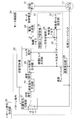
- FIG. 10 is a flowchart for describing a processing flow of a motor control unit when a user exercises a training exercise using the exercise apparatus according to the first to third embodiments of the present invention.
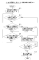
- FIG. 10 is a flowchart for describing a processing flow of a motor control unit when a user performs a rehabilitation exercise using the exercise apparatus according to the first to third embodiments of the present invention. It is a figure which shows the whole structure of the exercise
- the exercise apparatus 100 includes a movable mechanism unit 10 and a movable mechanism control unit 20 having a motor control unit 24 that controls a rotary motor 13 described later of the movable mechanism unit 10.
- the rotary motor 13 is an example of the “drive unit” in the present invention and an example of the “motor” in the present invention.
- the motor control unit 24 is an example of the “control unit” in the present invention.
- the movable mechanism control unit 20 is an example of the “motor control device” in the present invention.
- the movable mechanism unit 10 and the movable mechanism control unit 20 are output by a motor control current output by a motor control unit 24 of the movable mechanism control unit 20 described later and an encoder 17 (see FIG. 2) of the rotary motor 13 described later. Are connected to each other via a cable for transmitting position feedback and the like.
- the encoder 17 is an example of the “position detection unit” in the present invention.
- the movable mechanism unit 10 is configured to include a seat 11, an arm 12, a rotary motor 13, and a reduction gear 14.
- the arm 12 is an example of the “movable portion” in the present invention.
- the arm 12 is configured to be movable by the application of external force by the motion of the user.
- the motion is a motion of holding and moving the arm 12 in a state where the user is sitting on the seat 11 (a motion of rotating the arm 12 with the arm rotation shaft 15 as a rotation axis).
- the rotary motor 13 is configured to be able to move the arm 12 separately from the movement by the external force of the user. Specifically, based on the motor control current input from the movable mechanism control unit 20, the rotary motor 13 is rotationally driven with the motor rotary shaft 16 as a rotary shaft, and the driving force due to the rotation is motor rotary shaft 16 It is configured to be able to be applied to the arm 12 via the reduction gear 14 and the arm pivot shaft 15.
- the rotary motor 13 applies an external force to the arm 12 while sitting on the seat 11 and opposes the direction of the external force applied to the arm 12 by the user. It is possible to apply a directional load via the arm 12 and to allow a user to apply an auxiliary force in the direction along the direction of the external force applied to the arm 12 via the arm 12 It is done.
- the user can perform a training exercise or a rehabilitation exercise by applying an external force to the arm 12 and moving the arm 12 while sitting on the seat 11.
- the rotary motor 13 is provided with an encoder 17 (see FIG. 2) for detecting the current driving position (rotational position) of the rotary motor 13 corresponding to the current position of the arm 12. ing.
- the encoder 17 is configured to output the detected current drive position of the rotary motor 13 to the movable mechanism control unit 20 as position feedback.
- the encoder 17 may be an incremental encoder or an absolute encoder.
- the reduction gear 14 has a timing belt mechanism that rotates the arm rotation shaft 15 and the motor rotation shaft 16 in conjunction with each other.
- the reduction gear 14 reduces the rotational speed of the arm rotational shaft 15 with respect to the rotational speed of the motor rotational shaft 16 to increase the torque (driving force) generated by the rotational motor 13 and increase the torque.
- the torque is transmitted to the arm 12 via the motor rotation shaft 16, the reduction gear 14 and the arm rotation shaft 15.
- the movable mechanism control unit 20 is configured to include a setting input unit 21, a state display unit 22, a pattern command generation unit 23, and a motor control unit 24.
- the setting input unit 21 is an input device used when setting how the user operates the movable mechanism unit 10.
- the setting input unit 21 includes, for example, a display unit capable of touch panel operation, a button switch capable of pressing operation, and a rotary switch capable of rotating operation.
- the user operates the setting input unit 21 to select whether to use the movable mechanism unit 10 for training exercise or for rehabilitation exercise, or the intensity of the training exercise or rehabilitation exercise It is possible to set and so on. That is, the user operates the setting input unit 21 to select whether to drive the rotary motor 13 by the training control method described later or to drive the rotary motor 13 by the assist control method, or via the arm 12 It is possible to set the magnitude of the load or assisting force to be given to the user.
- the state display unit 22 is configured to be able to display a driving state including the driving force of the rotary motor 13. Specifically, the state display unit 22 is configured to be able to display the size of the load given to the user via the arm 12 of the movable mechanism unit 10 in the form of a graph. Further, the pattern command generation unit 23 changes the target drive position given to the rotary motor 13 when driving the rotary motor 13 with a preset drive pattern (for example, when driving the rotary motor 13 by an assist control method described later) Are configured to generate a pattern of (hereinafter referred to as a pattern command).
- the motor control unit 24 controls the drive of the rotary motor 13 (movement of the arm 12) by outputting the motor control current generated by the current generation unit 30 (see FIG. 2) described later to the rotary motor 13. It is configured.
- the motor control current is generated based on a torque command (target drive torque) given to the rotary motor 13.
- the motor control unit 24 determines the position from the encoder 17 Based on the feedback, it is configured to generate a motor control current that causes the rotary motor 13 to stay at the current drive position.
- the motor control unit 24 determines the pattern command from the pattern command generation unit 23. A motor control current is generated to drive the rotary motor 13 with a preset drive pattern.
- the motor control unit 24 is configured to compensate the torque command given to the rotary motor 13 based on the external force applied to the arm 12 by the user's exercise (training exercise or rehab exercise). There is. That is, the motor control unit 24 is configured to generate a compensation torque for compensating the torque command according to the direction and the magnitude of the external force due to the motion of the user.
- the motor control unit 24 uses the arm 12 according to the user's training exercise. By negatively feeding back the applied external force, the torque command given to the rotary motor 13 is compensated.
- the motor control unit 24 applies a load in the direction opposite to the direction of the external force applied to the arm 12 to the user via the arm 12. Is configured.
- the magnitude of the load is determined according to the strength of the training set by the user operating the setting input unit 21 and the magnitude of the external force applied to the arm 12 by the user at the time of the training exercise.
- a control method of the rotary motor 13 for applying a load to the user at the time of such training exercise will be referred to as a training control method.
- the “training control method” is an example of the “first control method” in the present invention.
- the motor control unit 24 is added to the arm 12 by the user's rehabilitation exercise when the user operates the setting input unit 21 and selects to use the movable mechanism unit 10 for rehabilitation exercise.
- the torque command given to the rotary motor 13 is compensated by positively feeding back the external force.
- motor control unit 24 applies the assisting force in the direction along the direction of the external force applied to arm 12 by the user to the user via arm 12. Is configured as.
- the magnitude of the assisting force is determined according to the strength of the rehabilitation set by the user operating the setting input unit 21 and the magnitude of the external force applied to the arm 12 by the user at the time of the rehabilitation exercise.
- assist control method a control method of the rotary motor 13 for applying the assisting force to the user at the time of such rehabilitation exercise.
- the “assist control method” is an example of the “second control method” in the present invention.
- the motor control unit 24 is configured to fix the target position of the rotary motor 13 when an emergency occurs. Specifically, the motor control unit 24 fixes the target drive position of the rotary motor 13 when the user operates the setting input unit 21 and performs an operation to stop the arm 12 in an emergency (an emergency stop operation). Thus, the arm 12 is configured to stop at the current position and to be in an immovable state. In addition, the motor control unit 24 performs predetermined two cases described later (when the difference between the target drive position of the rotary motor 13 and the current drive position becomes abnormal, and the compensation torque adjustment unit 35 (see FIG. 2) Also, when the torque input to the motor becomes abnormal), by fixing the target drive position of the rotary motor 13, the arm 12 is configured to be stopped at the current position to make it impossible to move. There is.
- the setting input unit 21 is operated by the user.
- the operation (return operation) for returning the arm 12 currently stopped to the initial position is performed, the arm 12 is returned to the initial position at a predetermined speed (the speed at which the user does not get injured) Is configured to drive the rotary motor 13.
- the motor control unit 24 includes a speed calculation unit 25, a state switching unit 26, a position command switching unit 27, a speed command generation unit 28, a torque command generation unit 29, and a current generation unit 30. And a compensation torque generation unit 31.
- the compensation torque generation unit 31 is an example of the “compensation force generation unit” in the present invention.
- the speed calculation unit 25 is configured by a differentiator or the like.
- the speed calculation unit 25 is configured to generate speed feedback (current drive speed of the rotary motor 13) by differentiating position feedback (current drive position of the rotary motor 13) from the encoder 17. .
- the speed calculation unit 25 is configured to output the speed feedback generated in this manner to the torque command generation unit 29 and the disturbance observer 32 described later.
- the state switching unit 26 is selected by the user when the user operates the setting input unit 21 to select whether to use the movable mechanism unit 10 for training exercise or for rehabilitation exercise. Accordingly, the state of the position command switching unit 27 and the state of the code switching unit 34 described later of the compensation torque generation unit 31 are switched.
- the state switching unit 26 uses position feedback from the encoder 17 as a position command (target drive position of the rotary motor 13).
- the position command switching unit 27 is configured to be switched to the first state (see r1 in FIG. 2) so as to be input to the speed command generation unit 28.
- the state switching unit 26 switches the state of the code switching unit 34 so as to negatively feed back torque caused by the external force of the user and output the torque to the compensation torque adjustment unit 35 (details will be described later). It is configured.
- the state switching unit 26 sets the pattern command from the pattern command generation unit 23 as the position command (target drive position of the rotary motor 13).
- the position command switching unit 27 is configured to be switched to the second state (see r2 in FIG. 2) so as to be input to the speed command generation unit 28.
- the state switching unit 26 switches the state of the code switching unit 34 so that the torque resulting from the external force of the user is positively fed back and output to the compensation torque adjusting unit 35 (details will be described later). It is configured.
- the state switching unit 26 fixes the target drive position of the rotary motor 13 when an emergency stop operation for stopping the movable mechanism 10 is performed by the operation of the setting input unit 21 by the user.
- the position command switching unit 27 is configured to be switched to the third state (refer to r ⁇ in FIG. 2) so that the command is input to the speed command generation unit 28. Further, in addition to the case where the user performs an emergency stop operation, the state switching unit 26 also makes a difference between the target drive position of the rotary motor 13 and the current drive position when abnormal (position command and position feedback).
- the position command switching unit 27 is not limited to the third one, even when the difference between the two becomes equal to or greater than a predetermined threshold) and the torque input to the compensation torque adjustment unit 35 becomes abnormal (the details will be described later). It is configured to switch to the state of.
- the speed command generation unit 28 is a control system that performs P control.
- the speed command generation unit 28 determines the position of the proportional element based on the difference between the input position command (target drive position of the rotary motor 13) and the position feedback (current drive position of the rotary motor 13 detected by the encoder 17). By multiplying the proportional gain Kp, a speed command (target driving speed of the rotary motor 13) is generated.
- the speed command generation unit 28 is configured to output the generated speed command to the torque command generation unit 29.
- the torque command generation unit 29 is a control system that performs PI control.
- the torque command generation unit 29 uses the speed proportional gain Kv of the proportional element and the integral element as the difference between the input speed command (target drive speed of the rotary motor 13) and the speed feedback (current drive speed of the rotary motor 13).
- the torque command (the target driving torque of the rotary motor 13) is generated by multiplying the integration time constant Ti by
- the torque command generation unit 29 is configured to output the generated torque command to the current generation unit 30.
- the current generator 30 is a control system that performs PI control.
- the current generation unit 30 receives the current torque gain (the torque command generated by the torque command generation unit 29 plus the compensation torque generated by the compensation torque generation unit 31), the current proportional gain Ki of the proportional element
- the motor control current (a current command corresponding to the target drive torque of the rotary motor 13) is generated by multiplying the integral time constant Tii of the integral element by.
- the current generator 30 is configured to output the generated motor control current to the rotary motor 13 of the movable mechanism 10.
- the compensation torque generation unit 31 is configured to generate a compensation torque for compensating the torque command output by the torque command generation unit 29.
- the compensation torque generation unit 31 is configured to include the disturbance observer 32, the no-load torque setting unit 33, the sign switching unit 34, and the compensation torque adjustment unit 35.
- the disturbance observer 32 estimates a disturbance torque (a torque caused by an external force or the like applied to the arm 12 by the motion of the user) applied to the rotary motor 13 in addition to the driving torque caused by the motor control current from the motor control unit 24.
- the disturbance observer 32 calculates the torque command (target drive torque of the rotary motor 13) generated by the torque command generation unit 29 and the speed feedback (current drive of the rotation motor 13) generated by the speed calculation unit 25.
- the disturbance torque applied to the rotary motor 13 is estimated on the basis of the speed.
- the no-load torque setting unit 33 is a torque (hereinafter referred to as no-load torque) that needs to be applied in advance to the rotary motor 13 in order not to move the arm 12 by an external force (for example, gravity) other than the external force of the user. It is provided to set and save.
- the no-load torque is measured at an early stage before the user performs an exercise (training exercise or rehab exercise) using the arm 12.
- the external force of the user among the disturbance torques applied to the rotary motor 13 by subtracting the no-load torque set in the no-load torque setting unit 33 from the disturbance torque estimated by the disturbance observer 32 The torque resulting from is calculated.
- the code switching unit 34 negatively feedbacks the torque resulting from the external force of the user calculated as described above and outputs the torque to the compensation torque adjustment unit 35 (a first state of the position command switching unit 27 (r1 in FIG. (See corresponding)) and positive feedback to be output to the compensation torque adjustment unit 35 (corresponding to the second state (see r2 in FIG. 2) of the position command switching unit 27) by the user (training control) It is provided to switch according to whether to drive the rotary motor 13 by a method or to select whether to drive the rotary motor 13 by an assist control method.
- the code switching unit 34 negatively feeds back the torque resulting from the external force of the user, and the compensation torque adjusting unit 35
- the torque resulting from the external force of the user is positively fed back and output to the compensation torque adjustment unit 35, It is comprised so that the code
- the compensation torque adjustment unit 35 is provided to adjust the magnitude of the compensation torque. Specifically, the compensation torque adjustment unit 35 sets the size of the torque (torque resulting from the external force of the user) input through the code switching unit 34 by the user operating the setting input unit 21 and setting the training. It is configured to adjust according to the intensity of exercise or rehabilitation exercise. Further, when the torque input through the code switching unit 34 is abnormal, the compensation torque adjustment unit 35 is configured to adjust the abnormal torque within the range of a predetermined limit value. When the torque input to the compensation torque adjustment unit 35 is abnormal, for example, the speed feedback output from the speed command generation unit 28 largely fluctuates due to the transient response, or the response gain of the disturbance observer 32 is correctly set.
- the torque input to the compensation torque adjustment unit 35 becomes excessively large due to the fact that the torque is not generated. Besides, assuming that the torque input to the compensation torque adjustment unit 35 is abnormal, the compensation torque adjustment is caused due to the abrupt change in the magnitude of the external force applied to the arm 12 due to the user's injury or the like. It is conceivable that the torque input to the unit 35 changes rapidly.
- the compensation torque adjustment unit 35 is configured to output the adjusted torque as a compensation torque to the current generation unit 30.
- the compensation torque adjustment unit 35 is configured to include an averaging filter, a smoothing filter, and the like.
- This smoothing filter may be a first-order lag filter such as a low pass filter, or may be a filter of another order.
- the compensation torque output from the compensation torque adjustment unit 35 is averaged and smoothed, so that the output of the compensation torque is suppressed from being dispersed or discontinuous.
- the processing flow is started when the user operates the setting input unit 21 and selects to use the movable mechanism unit 10 for training exercise.
- step S1 the state switching unit 26 switches the position command switching unit 27 to the first state (see r1 in FIG. 2).
- the position feedback from the encoder 17 is input to the speed command generation unit 28 as a position command.
- negative feedback of the torque (torque calculated by the estimation result of the disturbance observer 32 and the no-load torque set in the no-load torque setting unit 33) caused by the external force applied to the arm 12 by the user Not only the state of the position command switching unit 27 but also the state of the sign switching unit 34 can be switched by the state switching unit 26 so that the compensation torque adjustment unit 35 is input.
- step S2 a load opposite to the movement direction of the user and in accordance with the external force of the user is applied to the user via the arm 12, so the user holds and moves the arm 12. Enables training exercises to be performed. Then, the process proceeds to step S2.
- step S2 it is determined whether the user operates the setting input unit 21 to perform an emergency stop operation of the arm 12. If it is determined in step S2 that the user has not performed an emergency stop operation, the process proceeds to step S3.
- step S3 it is determined whether the torque input to the compensation torque adjustment unit 35 is abnormal.
- the compensation torque is caused by the fact that the velocity feedback output from the velocity command generation unit 28 largely fluctuates due to the transient response or the response gain of the disturbance observer 32 is not set correctly.
- the torque input to the adjustment unit 35 becomes excessively large, it is determined that the torque input to the compensation torque adjustment unit 35 is abnormal.
- step S3 when the torque input to the compensation torque adjustment unit 35 is rapidly changed due to the abrupt change in the magnitude of the external force applied to the arm 12 due to the user's injury or the like. Also, it is determined that the torque input to the guarantee torque adjustment unit 35 is abnormal.
- step S3 determines the torque input to the compensation torque adjustment unit 35 is not abnormal.
- step S4 it is determined whether or not the difference between the target drive position of the rotary motor 13 and the current drive position is abnormal (whether the difference between the position command and the position feedback is not less than a predetermined threshold) Be done. If it is determined in step S4 that the difference between the target position of the rotary motor 13 and the current position is not abnormal, the process returns to step S2. If it is determined in step S4 that the difference between the target position of the rotary motor 13 and the current position is abnormal, the process proceeds to step S5.
- step S5 Even when it is determined that the emergency stop operation has been performed by the user in step S2, the process proceeds to step S5. In addition, when it is determined in step S3 that the torque input to the compensation torque adjustment unit 35 is abnormal, the process also proceeds to step S5.
- step S5 the state switching unit 26 switches the position command switching unit 27 to the third state (see r ⁇ in FIG. 2).
- the target drive position of the rotary motor 13 is fixed, and the arm 12 of the movable mechanism 10 is stopped at the current position. Then, the process proceeds to step S6.
- step S6 it is determined whether or not the user operates the setting input unit 21 to perform a reset operation of the arm 12 (operation of returning the currently stopped arm 12 to the initial position). The determination in step S6 is repeated until it is determined that the reset operation has been performed by the user. When it is determined in step S6 that the reset operation has been performed by the user, the process proceeds to step S7.
- step S7 processing for gradually returning the arm 12 to the initial position is performed. That is, processing is performed to drive the rotary motor 13 so as to return the arm 12 to the initial position at a speed that does not cause a user injury. Then, the process ends.
- This processing flow is started when the user operates the setting input unit 21 and selects to use the movable mechanism unit 10 for rehabilitation exercise.
- step S11 the state switching unit 26 switches the position command switching unit 27 to the second state (see r2 in FIG. 2).
- the pattern command from the pattern command generation unit 23 is input to the speed command generation unit 28 as a position command.
- positive feedback of the torque (torque calculated by the estimation result of the disturbance observer 32 and the no-load torque set in the no-load torque setting unit 33) caused by the external force applied to the arm 12 by the user Not only the state of the position command switching unit 27 but also the state of the sign switching unit 34 can be switched by the state switching unit 26 so that the compensation torque adjustment unit 35 is input.
- step S12 the process proceeds to step S12.
- step S12 it is determined whether the user operates the setting input unit 21 to perform an emergency stop operation of the movable mechanism 10. If it is determined in step S12 that the user has not performed an emergency stop operation, the process proceeds to step S13.
- step S13 it is determined whether the torque input to the compensation torque adjustment unit 35 is abnormal. If it is determined in step S13 that the torque input to the compensation torque adjustment unit 35 is abnormal, the process proceeds to step S14.
- step S14 the state switching unit 26 switches the position command switching unit 27 to the first state (see r1 in FIG. 2).
- the motor control unit 24 performs control such that the arm 12 moving in a predetermined movement pattern remains at the current position. Then, the process proceeds to step S15.
- step S13 also when it is judged in the said step S13 that the torque input into the compensation torque adjustment part 35 is not abnormal, it progresses to step S15.
- step S15 it is determined whether the difference between the target drive position of the rotary motor 13 and the current drive position is abnormal. If it is determined in step S15 that the difference between the target position of the rotary motor 13 and the current position is not abnormal, the process returns to step S12. If it is determined in step S15 that the difference between the target position of the rotary motor 13 and the current position is abnormal, the process proceeds to step S16.
- step S12 Even when it is determined that the emergency stop operation has been performed by the user in step S12, the process proceeds to step S16. In addition, if it is determined in step S13 that the torque input to the compensation torque adjustment unit 35 is abnormal, the process proceeds to step S16.
- step S16 the state switching unit 26 switches the position command switching unit 27 to the third state (see r ⁇ in FIG. 2).
- the target drive position of the rotary motor 13 is fixed, and the arm 12 of the movable mechanism 10 is stopped at the current position. Then, the process proceeds to step S17.
- step S17 it is determined whether the user operates the setting input unit 21 to reset the arm 12. The determination in step S17 is repeated until it is determined that the reset operation has been performed by the user. When it is determined in step S17 that the reset operation has been performed by the user, the process proceeds to step S18.
- step S18 processing for gradually returning the arm 12 to the initial position is performed. That is, processing is performed to drive the rotary motor 13 so as to return the arm 12 to the initial position at a speed that does not cause a user injury. Then, the process ends.
- the arm 12 is kept at the current position based on the current drive position (position feedback) of the rotary motor 13 detected by the encoder 17.
- the motor control unit 24 is configured to drive 13.
- the user simply applies an external force to the arm 12 without performing a complicated setting operation such as setting in advance a drive pattern of the rotary motor 13 for moving the arm 12 in a predetermined movement pattern.
- a load in the direction opposite to the direction of the external force can be applied to the user via the arm 12.
- the motor control unit 24 is configured to drive the rotary motor 13 with the position (position feedback) as the target drive position (position command). This makes it possible to easily control the arm 12 to stay at the current position by using the detection result (position feedback) of the encoder 17.
- the load of the size according to the external force of the user is the arm in the direction opposite to the direction of the external force of the user.
- the motor control unit 24 is configured to be provided to the user via 12. Thereby, an appropriate load according to the physical strength of the user can be given to the user via the arm 12.
- the driving force applied to the arm 12 by the rotary motor 13 is included within the range of the predetermined limit value.
- the motor control unit 24 is configured to compensate. Thereby, it can be suppressed that the magnitude of the load given to the user via the arm 12 becomes larger than necessary.
- the disturbance observer 32 for estimating the disturbance applied to the arm 12 is provided, and from the estimation result by the disturbance observer 32, the arm 12 is not applied with the external force of the user.
- the motor control unit 24 is configured to calculate the external force of the user by subtracting the applied disturbance (no-load torque).
- the user is considered by considering the disturbance (no load torque) applied to the arm 12 in the state where the external force of the user is not applied.
- the external force of can be calculated accurately.
- the rotation is performed by the assist control method of applying the assisting force in the direction along the external force applied by the user to the user via the arm 12
- the motor control unit 24 is configured to be able to drive the motor 13.
- the driving force applied to the arm 12 by the rotary motor 13 is included within the range of the predetermined limit value.
- the motor control unit 24 is configured to compensate. As a result, the magnitude of the assisting force provided to the user via the arm 12 can be suppressed from becoming larger than necessary.
- the rotary motor 13 when the rotary motor 13 is driven by the training control method, the rotary motor is detected based on the current drive position (position feedback) of the rotary motor 13 detected by the encoder 17.
- the motor control is performed so as to drive the rotary motor 13 with a preset drive pattern (pattern command generated by the pattern command generation unit 23).
- the unit 24 is configured.
- a user who is required to perform a rehabilitation exercise can not easily move the arm 12 because a large external force can not be applied to the arm 12, and it may be difficult to obtain a sufficient rehabilitation effect.
- the rotary motor 13 at the time of assist control, the rotary motor 13 is driven with a drive pattern (pattern command generated by the pattern command generation unit 23) set in advance, so that the user can easily obtain a rehabilitation effect. can do.
- the rotary motor 13 when the rotary motor 13 is driven by the training control method, the rotary motor 13 is driven by the driving force compensated by negatively feeding back the external force of the user.
- the motor control unit 24 is configured to drive the rotary motor 13 with the driving force compensated by positively feeding back the external force of the user.
- the motor control unit 24 is configured to fix the target drive position of the rotary motor 13 when an emergency occurs. Thereby, since the arm 12 can be stopped when an emergency occurs, the safety of the user when the emergency occurs can be secured.
- the motor control unit 24 is configured to fix the target drive position of the rotary motor 13 when the user performs an emergency stop operation. Thereby, for example, when it is necessary to stop the arm 12 due to user's fatigue or the like, the arm 12 can be easily stopped by performing the emergency stop operation.
- the motor control unit 24 is configured to fix the target drive position of the rotary motor 13 when the estimation result by the disturbance observer 32 becomes abnormal.
- the estimation result of the disturbance observer 32 because the speed feedback output from the speed command generation unit 28 largely fluctuates due to the transient response or the response gain of the disturbance observer 32 is not set correctly.
- the arm 12 can be stopped. Also, stop the arm 12 even if the estimation result of the disturbance observer 32 becomes abnormal due to the abrupt change in the magnitude of the external force applied to the arm 12 due to the user's injury or the like. Can.
- the motor control unit 24 is configured to fix the target drive position of the rotary motor 13.
- the arm 12 is moved at a predetermined speed (the extent to which the user is not injured.
- the motor control unit 24 is configured to drive the rotary motor 13 so as to return to the initial position at or below the speed of. Thereby, it is possible to prevent the stopped arm 12 from moving until the user performs a reset operation.
- the arm 12 is controlled using, for example, an electromagnetic brake.
- a load auxiliary force
- the arm 12 is controlled using, for example, an electromagnetic brake.
- the load without delay auxiliary power
- an exercise apparatus 200 according to a second embodiment of the present invention will be described with reference to FIG.
- the user moves the arm 42 in the vertical direction, unlike the first embodiment in which the user performs an exercise (training exercise or rehabilitation exercise) by rotating the arm 12 (see FIG. 1).
- An example in which exercise is performed will be described.
- the exercise apparatus 200 includes a movable mechanism unit 40 and a movable mechanism control unit 20a having a motor control unit 24a for controlling a rotary motor 45 described later of the movable mechanism unit 40.
- the rotary motor 45 is an example of the “drive unit” in the present invention and an example of the “motor” in the present invention.
- the motor control unit 24a is an example of the "control unit” in the present invention.
- the movable mechanism control unit 20a is an example of the "motor control device" in the present invention.
- the movable mechanism portion 40 is configured to include a seat 41, an arm 42, an arm side pulley 43, a motor side pulley 44, a rotary motor 45, a reduction gear 46, and a movable mechanism support portion 47.
- the arm 42 is an example of the “movable portion” in the present invention.
- the arm 42 is configured to be movable in the vertical direction by applying an external force by the user's exercise (training exercise or rehabilitation exercise). Further, the rotation motor 45 is configured to be able to move the arm 42 in the vertical direction separately from the movement due to the external force of the user. Specifically, based on the motor control current input from the motor control unit 24a of the movable mechanism control unit 20a, the rotary motor 45 rotationally drives the motor rotation shaft 48 as a rotation shaft, and thereby the driving force by the rotation. Can be applied to the arm 42 via the motor rotation shaft 48, the reduction gear 46, the motor side pulley 44 and the arm side pulley 43.
- the arm side pulley 43 and the motor side pulley 44 constitute a timing belt mechanism that rotates in conjunction with each other.
- the driving force by the rotation of the rotary motor 45 is converted into driving force in the vertical direction through the timing belt mechanism consisting of the arm side pulley 43 and the motor side pulley 44, and the driving force in the vertical direction is transmitted to the arm 42. Granted.
- the movable mechanism support portion 47 is provided to support the arm 42, the arm side pulley 43, the motor side pulley 44, and the rotation motor 45.
- the rotary motor 45 is driven based on the motor control current from the motor control unit 24a of the movable mechanism control unit 20a to apply an external force to the arm 42 while sitting on the seat 41. It is possible to apply a load in the direction opposite to the direction of the external force applied to the arm 42 by the user to the user performing an exercise to move the arm 42 in the vertical direction via the arm 42, and the user
- the auxiliary force in the direction along the direction of the external force applied to the arm 42 is configured to be able to be applied via the arm 42.
- the user can perform a training exercise or a rehabilitation exercise by applying an external force to the arm 42 while moving on the seat 42 and moving the arm 42 in the vertical direction.
- the remaining structure of the second embodiment is similar to that of the aforementioned first embodiment.
- an exercise device 300 according to a third embodiment of the present invention will be described.
- the third embodiment unlike the first embodiment using the rotary motor 13 (see FIG. 1) to move the arm 12 (see FIG. 1), an example using the linear motor 53 to move the arm 52 Will be explained.
- the exercise apparatus 300 includes a movable mechanism unit 50 and a movable mechanism control unit 20b having a motor control unit 24b for controlling a linear motor 53 described later of the movable mechanism unit 50.
- the linear motor 53 is an example of the “drive unit” in the present invention and an example of the “motor” in the present invention.
- the motor control unit 24 b is an example of the “control unit” in the present invention.
- the movable mechanism control unit 20b is an example of the "motor control device" in the present invention.
- the movable mechanism unit 50 is configured to include a seat 51, an arm 52, a linear motor 53, and a linear scale 54.
- the arm 52 is an example of the “movable portion” in the present invention.
- the linear scale 54 is an example of the "position detection unit” in the present invention.
- the arm 52 is configured to be movable in the horizontal direction when an external force is applied by a user's exercise (training exercise or rehabilitation exercise). Further, the linear motor 53 is configured to be capable of moving the arm 52 in the horizontal direction separately from the movement by the external force of the user. Specifically, the linear motor 53 is driven to generate thrust in the horizontal direction based on the motor control current input from the motor control unit 24b of the movable mechanism control unit 20b, whereby the thrust in the horizontal direction is generated. Is configured to be able to be applied to the arm 52.
- the linear motor 53 is driven based on the motor control current from the motor control unit 24b of the movable mechanism control unit 20b to apply an external force to the arm 52 in a state lying on the sheet 51. It is possible to apply a load in the direction opposite to the direction of the external force applied to the arm 52 by the user to the user performing an exercise to move the arm 52 in the horizontal direction, and the user can An auxiliary force in a direction along the direction of the external force applied to the electrode 52 can be applied through the arm 52.
- the user can perform a training exercise or a rehabilitation exercise by applying an external force to the arm 52 while lying on the sheet 51 to move the arm 52 in the horizontal direction.
- the horizontal drive position of the linear motor 53 is detected by the linear scale 54. Then, the horizontal drive position of the linear motor 53 detected by the linear scale 54 is output toward the movable mechanism control unit 20b as position feedback.
- the horizontal drive position of the linear motor 53 detected by the linear scale 54 is output toward the movable mechanism control unit 20b as position feedback.
- the third embodiment unlike the first and second embodiments, since there is no decelerating mechanism provided between the linear motor 53 and the arm 52, it is not necessary to consider non-linear elements such as backlash by the decelerating mechanism, Control of the drive of the linear motor 53 can be performed more accurately.
- the remaining structure of the third embodiment is similar to that of the aforementioned first embodiment.
- processing flow of the motor control unit 24b of the movable mechanism control unit 20b when the user performs exercise (training exercise or rehabilitation exercise) using the exercise apparatus 300 according to the third embodiment is also the first embodiment (FIG. 3). And FIG. 4).
- the movable mechanism control unit as an example of the motor control device according to the present invention is used to control the drive of the movable mechanism portion of the exercise apparatus.
- the invention is not limited to this.
- the motor control device may be used to control the drive of a drive mechanism used in the general industry.
- the external force applied to the arm (movable portion) by the user is estimated using the disturbance observer.
- the present invention is not limited to this.
- the external force applied to the movable portion by the user may be estimated by another component such as an external torque sensor or a force sensor.
- the setting input unit configured by the display unit capable of touch panel operation, the button switch capable of pressing operation, the rotary switch capable of rotating operation, etc. is extremely useful.
- this invention is not limited to this.
- an emergency stop operation may be performed using a dead man switch. In this way, it is possible to reliably stop the exercise device when the user stops exercising.
- the present invention is not limited to this. In the present invention, if a rotary motor capable of outputting large torque at low speed is used, it is not necessary to provide a reduction gear between the arm and the rotary motor.
- the reduction gear of the first and second embodiments is a reduction gear having a timing belt mechanism, a gear reduction gear formed of a spur gear or a worm, a reduction gear formed of a chain and a sprocket, or the like may be used. Good.
- the target drive position of the rotary motor is fixed when an emergency occurs while the rotary motor (drive unit) is being driven by the training control method (first control method).
- the motor control unit control unit
- the motor control unit may be configured to perform control to make the arm (movable unit) in an immovable state, but the present invention is not limited to this.
- the arm in the state where the rotary motor is driven by the training control method, when an emergency occurs, the arm can be freely moved by setting the driving force applied to the arm to zero by the rotary motor.
- the motor control unit (control unit) may be configured to perform control to According to this configuration, when an emergency occurs during the user's training exercise, the load applied to the user via the arm can be made zero. This allows the user to easily move the arm to a safe position if an emergency occurs during a training exercise.
Abstract
Description
まず、図1を参照して、本発明の第1実施形態による運動装置100の構成について説明する。 First Embodiment
First, the configuration of an
次に、図5を参照して、本発明の第2実施形態による運動装置200について説明する。この第2実施形態では、ユーザがアーム12(図1参照)を回動させることにより運動(トレーニング運動またはリハビリ運動)を行う上記第1実施形態と異なり、ユーザがアーム42を上下方向に移動させることにより運動を行う例について説明する。 Second Embodiment
Next, an
次に、図6を参照して、本発明の第3実施形態による運動装置300について説明する。この第3実施形態では、アーム12(図1参照)を移動させるために回転モータ13(図1参照)を用いる上記第1実施形態と異なり、アーム52を移動させるためにリニアモータ53を用いる例について説明する。 Third Embodiment
Next, with reference to FIG. 6, an
Claims (16)
- ユーザの運動によって外力が加えられることにより移動可能に構成された可動部(12、42、52)と、
前記ユーザの外力による移動とは別に前記可動部を移動させるための駆動力を前記可動部に付与する駆動部(13、45、53)と、
前記可動部の現在の位置に対応する前記駆動部の現在の駆動位置を検出する位置検出部(17、54)と、
前記駆動部の駆動を制御する制御部(24、24a、24b)と、
を備え、
前記制御部は、前記位置検出部により検出された前記駆動部の現在の駆動位置に基づいて、前記可動部を現在の位置に留まらせるような第1制御方法により前記駆動部を駆動する、運動装置。 A movable part (12, 42, 52) configured to be movable by the application of external force by the motion of the user;
A driving unit (13, 45, 53) for applying a driving force for moving the movable unit to the movable unit separately from the movement by the external force of the user;
A position detection unit (17, 54) for detecting the current drive position of the drive unit corresponding to the current position of the movable unit;
A control unit (24, 24a, 24b) for controlling the drive of the drive unit;
Equipped with
The control unit drives the drive unit by a first control method that causes the movable unit to stay at the current position based on the current drive position of the drive unit detected by the position detection unit. apparatus. - 前記制御部は、前記第1制御方法により前記駆動部を駆動する際に、前記可動部を現在位置に留まらせるように、前記位置検出部により検出された前記駆動部の現在の駆動位置を目標駆動位置として前記駆動部を駆動する、請求項1に記載の運動装置。 The control unit targets the current drive position of the drive unit detected by the position detection unit so as to keep the movable unit at the current position when driving the drive unit according to the first control method. The exercise device according to claim 1, wherein the drive unit is driven as a drive position.
- 前記制御部は、前記第1制御方法により前記駆動部を駆動する際に、前記ユーザの外力に応じた大きさの負荷を、前記ユーザの外力の方向とは反対方向に、前記可動部を介して前記ユーザに付与する、請求項2に記載の運動装置。 When the control unit drives the drive unit according to the first control method, the control unit causes a load having a magnitude according to the external force of the user to be opposite to the external force direction of the user via the movable unit. The exercise device according to claim 2, wherein the exercise device is provided to the user.
- 前記制御部は、前記第1制御方法により前記駆動部を駆動する際に、前記駆動部により前記可動部に付与される駆動力が所定の制限値の範囲内に含まれるように補償する、請求項1に記載の運動装置。 When driving the drive unit according to the first control method, the control unit compensates so that the driving force applied to the movable unit by the drive unit is included in a range of a predetermined limit value. The exercise apparatus according to Item 1.
- 前記可動部に加えられる外乱の推定を行う外乱オブザーバ(32)をさらに備え、
前記制御部は、前記ユーザの外力により前記可動部が移動される際に、前記外乱オブザーバによる推定結果から、前記ユーザの外力が加えられていない状態において前記可動部に加えられている外乱を減算することにより、前記ユーザの外力を算出するように構成されている、請求項3に記載の運動装置。 It further comprises a disturbance observer (32) for estimating the disturbance applied to the movable part,
The control unit subtracts the disturbance applied to the movable part in a state where the external force of the user is not applied, from the estimation result by the disturbance observer when the movable part is moved by the external force of the user The exercise device according to claim 3, wherein the exercise device is configured to calculate the external force of the user. - 前記制御部は、
前記第1制御方法に加えて、
前記ユーザの加えた外力の方向に沿った方向の補助力を前記可動部を介して前記ユーザに付与する第2制御方法により、前記駆動部を駆動することが可能な、請求項1に記載の運動装置。 The control unit
In addition to the first control method,
2. The drive unit according to claim 1, wherein the drive unit can be driven by a second control method of applying an assisting force in a direction along the direction of the external force applied by the user to the user via the movable unit. Exercise equipment. - 前記制御部は、前記第2制御方法により前記駆動部を駆動する際に、前記駆動部により前記可動部に付与される駆動力が所定の制限値の範囲内に含まれるように補償する、請求項6に記載の運動装置。 When driving the drive unit according to the second control method, the control unit compensates so that the drive force applied to the movable unit by the drive unit is included in a range of a predetermined limit value. The exercise apparatus according to Item 6.
- 前記制御部は、
前記第1制御方法により前記駆動部を駆動する場合には、前記位置検出部により検出された前記駆動部の現在の駆動位置に基づいて前記駆動部を駆動する一方、
前記第2制御方法により前記駆動部を駆動する場合には、予め設定された駆動パターンで前記駆動部を駆動する、請求項6に記載の運動装置。 The control unit
When driving the drive unit by the first control method, the drive unit is driven based on the current drive position of the drive unit detected by the position detection unit,
The exercise apparatus according to claim 6, wherein when driving the drive unit by the second control method, the drive unit is driven with a drive pattern set in advance. - 前記制御部は、
前記第1制御方法により前記駆動部を駆動する場合には、前記ユーザの外力を負帰還させることにより補償された駆動力で前記駆動部を駆動する一方、
前記第2制御方法により前記駆動部を駆動する場合には、前記ユーザの外力を正帰還させることにより補償された駆動力で前記駆動部を駆動する、請求項6に記載の運動装置。 The control unit
When driving the drive unit according to the first control method, the drive unit is driven with a driving force compensated by negatively feeding back the external force of the user.
The exercise apparatus according to claim 6, wherein when driving the drive unit by the second control method, the drive unit is driven by a driving force compensated by positively feeding back the external force of the user. - 前記制御部は、非常状態が発生した場合に、前記駆動部の目標駆動位置を固定する、請求項1に記載の運動装置。 The exercise apparatus according to claim 1, wherein the control unit fixes a target drive position of the drive unit when an emergency occurs.
- 前記非常状態が発生した場合は、前記ユーザにより非常停止操作が行われた場合を含む、請求項10に記載の運動装置。 The exercise device according to claim 10, including a case where an emergency stop operation is performed by the user when the emergency state occurs.
- 前記可動部に加えられる外乱の推定を行う外乱オブザーバをさらに備え、
前記非常状態が発生した場合は、前記外乱オブザーバによる推定結果が異常となった場合を含む、請求項10に記載の運動装置。 It further comprises a disturbance observer that estimates the disturbance applied to the movable part,
The exercise apparatus according to claim 10, including the case where the estimation result by the disturbance observer becomes abnormal when the emergency state occurs. - 前記非常状態が発生した場合は、前記駆動部の現在の駆動位置と目標駆動位置との差が所定のしきい値以上となった場合を含む、請求項10に記載の運動装置。 The exercise apparatus according to claim 10, wherein the case where the emergency state occurs includes the case where the difference between the current drive position of the drive unit and the target drive position becomes equal to or more than a predetermined threshold value.
- 前記制御部は、前記駆動部の目標駆動位置が固定され、かつ、前記ユーザによりリセット操作が行われた場合に、前記可動部を所定の速度以下で初期位置に戻すように前記駆動部を駆動する、請求項10~13のいずれか1項に記載の運動装置。 The control unit drives the drive unit to return the movable unit to an initial position at a predetermined speed or less when the target drive position of the drive unit is fixed and the reset operation is performed by the user. The exercise device according to any one of claims 10 to 13.
- 外力が加えられることにより移動可能に構成された可動部(12、42、52)に、前記外力による移動とは別に前記可動部を移動させるための駆動力を付与するモータ(13、45、53)の駆動を制御するモータ制御部(24、24a、24b)を備え、
前記モータ制御部は、前記可動部の現在の位置に対応する前記モータの現在の駆動位置を検出する位置検出部(17、54)により検出された前記モータの現在の駆動位置に基づいて、前記可動部を現在の位置に留まらせるように前記駆動部を駆動する、モータ制御装置。 A motor (13, 45, 53) for applying a driving force for moving the movable portion to the movable portion (12, 42, 52) configured to be movable by the application of an external force separately from the movement by the external force Motor control unit (24, 24a, 24b) for controlling the drive of
The motor control unit is configured to detect the current drive position of the motor corresponding to the current position of the movable unit, based on the current drive position of the motor detected by the position detection unit (17, 54). A motor control device, which drives the drive unit to hold the movable unit at a current position. - 外力が加えられることにより移動可能に構成された可動部(12、42、52)を前記外力による移動とは別に移動させるための駆動力を前記可動部に付与するモータ(13、45、53)の、前記可動部の現在の位置に対応する現在の駆動位置を検出するステップと、
検出された前記モータの現在の駆動位置に基づいて、前記可動部を現在の位置に留まらせるように前記モータの駆動を制御するステップとを備える、モータ制御方法。 A motor (13, 45, 53) for applying a driving force to the movable portion to move the movable portion (12, 42, 52) configured to be movable by the application of an external force separately from the movement by the external force Detecting a current drive position corresponding to the current position of the movable part;
Controlling the drive of the motor so as to keep the movable part at the current position based on the detected current drive position of the motor.
Priority Applications (3)
| Application Number | Priority Date | Filing Date | Title |
|---|---|---|---|
| CN201180072744.9A CN103733155B (en) | 2011-08-03 | 2011-08-03 | Telecontrol equipment |
| PCT/JP2011/067738 WO2013018205A1 (en) | 2011-08-03 | 2011-08-03 | Exercise device, motor control device, and motor control method |
| JP2013526686A JP5871001B2 (en) | 2011-08-03 | 2011-08-03 | Exercise device, motor control device, and motor control method |
Applications Claiming Priority (1)
| Application Number | Priority Date | Filing Date | Title |
|---|---|---|---|
| PCT/JP2011/067738 WO2013018205A1 (en) | 2011-08-03 | 2011-08-03 | Exercise device, motor control device, and motor control method |
Publications (1)
| Publication Number | Publication Date |
|---|---|
| WO2013018205A1 true WO2013018205A1 (en) | 2013-02-07 |
Family
ID=47628768
Family Applications (1)
| Application Number | Title | Priority Date | Filing Date |
|---|---|---|---|
| PCT/JP2011/067738 WO2013018205A1 (en) | 2011-08-03 | 2011-08-03 | Exercise device, motor control device, and motor control method |
Country Status (3)
| Country | Link |
|---|---|
| JP (1) | JP5871001B2 (en) |
| CN (1) | CN103733155B (en) |
| WO (1) | WO2013018205A1 (en) |
Cited By (4)
| Publication number | Priority date | Publication date | Assignee | Title |
|---|---|---|---|---|
| JP2015173859A (en) * | 2014-03-17 | 2015-10-05 | 三菱電機エンジニアリング株式会社 | Device and method for controlling exercise therapy apparatus |
| JP2017030081A (en) * | 2015-07-30 | 2017-02-09 | ファナック株式会社 | Industrial robot system and control method for same |
| JP2020137802A (en) * | 2019-02-28 | 2020-09-03 | 上銀科技股▲分▼有限公司 | Upper limb training system and control method |
| US11123608B2 (en) | 2019-03-05 | 2021-09-21 | Hiwin Technologies Corp. | Upper limb training system and control method thereof |
Families Citing this family (2)
| Publication number | Priority date | Publication date | Assignee | Title |
|---|---|---|---|---|
| JP7194326B2 (en) * | 2017-04-13 | 2022-12-22 | 株式会社ジェイテクト | motor controller |
| CN110787026B (en) * | 2019-11-11 | 2022-04-12 | 上海电气集团股份有限公司 | Motion abnormity protection method based on multi-sensor information and rehabilitation equipment |
Citations (4)
| Publication number | Priority date | Publication date | Assignee | Title |
|---|---|---|---|---|
| JPS5851748U (en) * | 1981-10-07 | 1983-04-08 | セノ−株式会社 | muscle strength training equipment |
| JPH01110374A (en) * | 1987-09-30 | 1989-04-27 | Kurt Berroth | Apparatus for positive training of muscle power |
| JP2007307180A (en) * | 2006-05-19 | 2007-11-29 | Matsushita Electric Ind Co Ltd | Rehabilitation apparatus |
| JP2009225845A (en) * | 2008-03-19 | 2009-10-08 | Hitachi Ltd | Training system and control method and apparatus for training machine |
Family Cites Families (8)
| Publication number | Priority date | Publication date | Assignee | Title |
|---|---|---|---|---|
| JP2002272795A (en) * | 2001-03-14 | 2002-09-24 | Japan Science & Technology Corp | Upper limb rehabilitation training system |
| JP2005348779A (en) * | 2004-06-08 | 2005-12-22 | Asahi Kasei Engineering Kk | Kinetic rehabilitation and training system |
| JP4183696B2 (en) * | 2005-06-07 | 2008-11-19 | 丸善工業株式会社 | Trunk strength training machine with power assist |
| CN101007205A (en) * | 2006-01-27 | 2007-08-01 | 明根股份有限公司 | Programmable controlling drag device for body-building equipment and method thereof |
| CN101347664A (en) * | 2007-07-20 | 2009-01-21 | 王国梁 | Improved motor control device for providing kinetic resistance and automatic backrush efficiency |
| JP5308685B2 (en) * | 2008-02-01 | 2013-10-09 | パナソニックヘルスケア株式会社 | Passive exercise equipment |
| JP5028348B2 (en) * | 2008-07-07 | 2012-09-19 | パナソニック株式会社 | Oscillating motion device |
| CN101810925B (en) * | 2009-02-19 | 2013-08-07 | 杨华平 | Intelligent electromagnetic fitness equipment damper |
-
2011
- 2011-08-03 CN CN201180072744.9A patent/CN103733155B/en not_active Expired - Fee Related
- 2011-08-03 JP JP2013526686A patent/JP5871001B2/en not_active Expired - Fee Related
- 2011-08-03 WO PCT/JP2011/067738 patent/WO2013018205A1/en active Application Filing
Patent Citations (4)
| Publication number | Priority date | Publication date | Assignee | Title |
|---|---|---|---|---|
| JPS5851748U (en) * | 1981-10-07 | 1983-04-08 | セノ−株式会社 | muscle strength training equipment |
| JPH01110374A (en) * | 1987-09-30 | 1989-04-27 | Kurt Berroth | Apparatus for positive training of muscle power |
| JP2007307180A (en) * | 2006-05-19 | 2007-11-29 | Matsushita Electric Ind Co Ltd | Rehabilitation apparatus |
| JP2009225845A (en) * | 2008-03-19 | 2009-10-08 | Hitachi Ltd | Training system and control method and apparatus for training machine |
Cited By (6)
| Publication number | Priority date | Publication date | Assignee | Title |
|---|---|---|---|---|
| JP2015173859A (en) * | 2014-03-17 | 2015-10-05 | 三菱電機エンジニアリング株式会社 | Device and method for controlling exercise therapy apparatus |
| US9713744B2 (en) | 2014-03-17 | 2017-07-25 | Mitsubishi Electric Engineering Company, Limited | Exercise therapy device |
| JP2017030081A (en) * | 2015-07-30 | 2017-02-09 | ファナック株式会社 | Industrial robot system and control method for same |
| US10011017B2 (en) | 2015-07-30 | 2018-07-03 | Fanuc Corporation | Industrial robot system and control method thereof |
| JP2020137802A (en) * | 2019-02-28 | 2020-09-03 | 上銀科技股▲分▼有限公司 | Upper limb training system and control method |
| US11123608B2 (en) | 2019-03-05 | 2021-09-21 | Hiwin Technologies Corp. | Upper limb training system and control method thereof |
Also Published As
| Publication number | Publication date |
|---|---|
| JPWO2013018205A1 (en) | 2015-03-02 |
| JP5871001B2 (en) | 2016-03-01 |
| CN103733155B (en) | 2016-02-17 |
| CN103733155A (en) | 2014-04-16 |
Similar Documents
| Publication | Publication Date | Title |
|---|---|---|
| WO2013018205A1 (en) | Exercise device, motor control device, and motor control method | |
| JP5360254B2 (en) | Torque detection method and arm device | |
| JP3929230B2 (en) | Exercise therapy equipment | |
| JP6114837B2 (en) | Training equipment | |
| US7211985B2 (en) | Training device | |
| US10730184B2 (en) | Robot arm control system | |
| WO2011145476A1 (en) | Motor control apparatus | |
| JP6305283B2 (en) | Power system control system | |
| JP6043231B2 (en) | Electric motor control device | |
| WO2007138668A1 (en) | Door device for elevator | |
| JP2007196829A (en) | Electric power steering device | |
| JP5585218B2 (en) | Elevator door control device | |
| JP4618433B2 (en) | Flexible control device and flexible control method for manipulator | |
| US10092368B2 (en) | Medical apparatus with a medical optical appliance and a holding device and method for operating the medical apparatus | |
| JP2005337812A (en) | Material testing machine | |
| KR102228527B1 (en) | Method and apparatus for controlling wearable robot | |
| JP2019097578A (en) | Motion training device | |
| Kiyota et al. | Proposal of power-assisted cart based on inherently safe control | |
| JP2019097584A (en) | Motion training device | |
| JP4042072B2 (en) | Training equipment | |
| JP2020176834A (en) | Load testing device | |
| KR20230102084A (en) | Rehabilitation robot system method for controlling rehabilitation robot | |
| JP2007175170A (en) | Load varying device | |
| KR102251348B1 (en) | Driving module for wearabel robot | |
| JP2019097586A (en) | Motion training device |
Legal Events
| Date | Code | Title | Description |
|---|---|---|---|
| WWE | Wipo information: entry into national phase |
Ref document number: 201180072744.9 Country of ref document: CN |
|
| 121 | Ep: the epo has been informed by wipo that ep was designated in this application |
Ref document number: 11870410 Country of ref document: EP Kind code of ref document: A1 |
|
| ENP | Entry into the national phase |
Ref document number: 2013526686 Country of ref document: JP Kind code of ref document: A |
|
| NENP | Non-entry into the national phase |
Ref country code: DE |
|
| 122 | Ep: pct application non-entry in european phase |
Ref document number: 11870410 Country of ref document: EP Kind code of ref document: A1 |