JP3925836B2 - Tire vulcanizing mold and tire vulcanized by the mold - Google Patents
Tire vulcanizing mold and tire vulcanized by the mold Download PDFInfo
- Publication number
- JP3925836B2 JP3925836B2 JP2001104775A JP2001104775A JP3925836B2 JP 3925836 B2 JP3925836 B2 JP 3925836B2 JP 2001104775 A JP2001104775 A JP 2001104775A JP 2001104775 A JP2001104775 A JP 2001104775A JP 3925836 B2 JP3925836 B2 JP 3925836B2
- Authority
- JP
- Japan
- Prior art keywords
- mold
- tire
- block
- knife blade
- inclination angle
- Prior art date
- Legal status (The legal status is an assumption and is not a legal conclusion. Google has not performed a legal analysis and makes no representation as to the accuracy of the status listed.)
- Expired - Lifetime
Links
Images


Classifications
-
- B—PERFORMING OPERATIONS; TRANSPORTING
- B60—VEHICLES IN GENERAL
- B60C—VEHICLE TYRES; TYRE INFLATION; TYRE CHANGING; CONNECTING VALVES TO INFLATABLE ELASTIC BODIES IN GENERAL; DEVICES OR ARRANGEMENTS RELATED TO TYRES
- B60C11/00—Tyre tread bands; Tread patterns; Anti-skid inserts
- B60C11/03—Tread patterns
- B60C11/12—Tread patterns characterised by the use of narrow slits or incisions, e.g. sipes
- B60C11/1204—Tread patterns characterised by the use of narrow slits or incisions, e.g. sipes with special shape of the sipe
- B60C2011/1213—Tread patterns characterised by the use of narrow slits or incisions, e.g. sipes with special shape of the sipe sinusoidal or zigzag at the tread surface
Landscapes
- Tires In General (AREA)
- Moulds For Moulding Plastics Or The Like (AREA)
- Heating, Cooling, Or Curing Plastics Or The Like In General (AREA)
Description
【0001】
【発明の属する技術分野】
本発明はタイヤ加硫用金型に関し、さらに詳細には金型が分割モールドであって、製品タイヤの排水性、制動性、旋回性、耐摩耗性などに影響を与えることなく、金型の損傷を防止するタイヤ加硫用金型及び該金型により加硫されたタイヤに関する。
【0002】
【従来の技術】
タイヤを加硫するための金型として、図4(a)に、概略平面図を示すように、タイヤ加硫用モールドのタイヤ周方向に相当する金型の周方向Rに対して直角に金型の周方向Rを分割した分割モールドとが使用される。なお、図4(a)の破線Dはタイヤ加硫用金型の分割位置である。
分割モールドは、通常、タイヤ赤道線を境に上下2分割され、前記上下に分割された金型は上下とも金型の周方向に対して直角に7〜11個程度の分割モールド片に分割されている。図4(a)に示した例では、MP1〜MP8の8個のモールド片に分割されていて、隣接する前記モールド片間の1〜2mm程度の隙間が未加硫タイヤに含まれるガス抜きの機能を果たすものである。
【0003】
【発明が解決しようとする課題】
タイヤ踏面部には、タイヤの制動性、排水性、旋回性等の要求特性を満たすための細い切り欠き部いわゆるサイプの凹部が配されている。従って、前記凹部を形成するため前記凹部に対応する位置のモールドの内面部には、タイヤのサイプ形成用ナイフブレードがモールド内面に対して略垂直に金型径方向内側に向かって配されている。通常、前記ナイフブレードの厚さは0.2mm〜1mm、同高さは1mm〜10mm、長さは3mm〜4mm程度で、一般に、材質がステンレスから成っている。
【0004】
図4(b)は、タイヤブロック部に対応する金型内面部に金型の周方向分割位置Dがない箇所(以下、分割位置非含有ブロック形成部と言う)の金型内面部1の概略平面図で、タイヤサイプ形成用ナイフブレードB1〜B5の長さ方向に沿った直線43と金型の幅方向に平行な直線3との交差角は全て同一交差角度θ11で配され、その形状は全て同一形状である。図4(c)はタイヤブロック部に対応する金型内面部に金型の周方向分割位置Dがある箇所(以下、分割位置含有ブロック形成部と言う)の金型内面部1の概略平面図で、図4(b)とは異なり、タイヤサイプ形成用ナイフブレードB1〜B5の内、金型の周方向分割位置Dを跨って配されるナイフブレードB2、B3は、前記分割位置D近辺でナイフブレードの一部が省略、削除されナイフブレードB1、B4、B5に比較して形状が小さくなっている。その理由は、金型の周方向分割位置Dを跨って配されるナイフブレードは、前記分割位置Dにおいて分割され複数のナイフブレード分割片となり、分割されたナイフブレード分割片の内、周方向分割位置D近辺の小さい方のナイフブレード分割片は剛性が低くなり、前記分割位置D近辺の小さい方のナイフブレード分割片を金型に残した状態にしておくと、加硫済みタイヤから加硫金型を外す場合、各分割モールド片(図4ではMP1〜MP8)がタイヤ加硫金型の中心から金型外径外側外側方向へ放射状に移動して、タイヤから取り外される際に、モールド片端部の分割位置D近辺の小さい方のナイフブレード分割片は、ねじれ等の力を受けて歪みが生じやすくなり損傷しやすいので金型から省略、削除されているからである。
【0005】
前記のような構成のナイフブレードを配したモールドによって、タイヤを加硫した場合、金型ナイフブレード部の損傷は避けることができるが、本来必要な形状のサイプの一部が欠落した形状のサイプがタイヤに配される。その結果、排水性、制動性、旋回性、耐摩耗性などの点から本来必要とするサイプ機能が充分発揮出来ず、該分割モールドによって、加硫製造されたタイヤは、サイプが本来果たすべき排水性、制動性、旋回性、耐摩耗性などのタイヤ性能が充分発揮出来なくなるのみでなく、踏面部の不均一摩耗が生じる。
【0006】
本発明の目的は、タイヤ加硫用分割モールドを用いてタイヤの排水性、制動性、旋回性、耐摩耗性などを低下させることなくタイヤに本来必要な機能が充分発揮出来る形状のサイプをタイヤに配することができるとともに、前記サイプ形成用ナイフブレードのタイヤ加硫時損傷を防止することができる分割モールドを提供するところにある。
【0007】
【課題を解決するための手段】
上記課題を解決するために、本発明請求項1のタイヤ加硫製造用金型は、
タイヤ周方向踏面部に周期性をもって繰り返し配列された各ブロックに、タイヤ幅方向に平行な直線に対して傾斜角を有すると共にタイヤ幅方向に延びる複数のサイプを一定間隔ごとに形成する複数のナイフブレードが金型内面のブロック形成部に取り付けられた分割モールド型のタイヤ加硫用金型において、
上記金型のブロック形成部のうち、金型幅方向にほぼ平行に延びる金型分割位置を備えた分割位置含有ブロック形成部では、
当該分割位置含有ブロック形成部以外のブロック形成部に形成された傾斜角θ11と同一乃至略同一の傾斜角θ1を有する複数のナイフブレードが取り付けられており、
前記傾斜角θ1では前記金型分割位置を跨るナイフブレードについては、当該ナイフブレードの前記分割位置に近い側を前記分割位置から離すことによって、前記金型分割位置を跨らない傾斜角θ2を有したナイフブレードが取り付けられていることを特徴とするタイヤ加硫用金型である。
ここで、「傾斜角」とは、「ナイフブレードライン(ナイフブレードが描く線)の長さ方向に沿った直線」と「金型の幅方向に平行な直線」との交差角度のことを言う。
なお、前記金型分割位置を跨らない傾斜角θ2を有したナイフブレードが取り付けられているとは、前記金型分割位置に隣り合い金型分割位置を跨らないナイフブレードの2本共が傾斜角θ2を有している場合と1本が傾斜角θ2、残りの1本が傾斜角θ3(傾斜角θ1よりも小のもの)であってもよい。
本発明請求項2のタイヤ加硫製造用金型は、
前記分割位置含有ブロック形成部において、
分割位置寄りで前記分割位置を挟んで隣り合う2本のナイフブレードラインと該ブロックを形成するために金型内面に設けられた凹部の2本の金型周方向ラインとで囲まれた面積をS2、
分割位置寄りの1本のナイフブレードライン、該分割位置寄りの1本のナイフブレードラインの隣りの1本のナイフブレードライン及び該ブロックを形成するために金型内面に設けられた凹部の2本の金型周方向ラインとで囲まれた面積をS1、S3、
上記以外で隣り合う2本のナイフブレードラインと該ブロックを形成するために金型内面に設けられた凹部の2本の金型周方向ラインとで囲まれた面積をSA、
前記ブロックを形成するために金型内面に設けられた凹部内に金型分割位置を有しない分割位置非含有ブロック形成部において、
隣り合う2本のナイフブレードラインと該ブロックを形成するために金型内面に設けられた凹部の2本の金型周方向ラインとで囲まれた面積をSB、
とした場合、
SA=SB、
S1、S2、S3が0.7SA〜1.3SAの範囲となるようにナイフブレードを配することを特徴とする金型であり、分割位置寄りで前記分割位置を挟んで隣り合う2本のナイフブレードラインの上記傾斜角を変更することによってS1、S2、S3が0.7SA〜1.3SAの範囲となるようにナイフブレードを配する。この場合、傾斜角は分割位置寄りで前記分割位置を挟んで隣り合う2本のナイフブレードラインはこの2本のナイフブレードライン以外のナイフブレードラインの傾斜角と異ならせ、当該ナイフブレードの前記分割位置に近い側を前記分割位置から離す。
本発明請求項3のタイヤは本発明の金型によって加硫製造されたタイヤであって、タイヤ周方向踏面部に周期性をもって繰り返し配列された各ブロックに、タイヤ幅方向に平行な直線に対して傾斜角を有すると共にタイヤ幅方向に延びる複数のサイプを一定間隔ごとに形成された空気入りタイヤにおいて、
上記ブロックのうち、タイヤ幅方向にほぼ平行に延びる金型分割位置を有する分割位置含有ブロックでは、
当該分割位置含有ブロック以外のブロックに形成された傾斜角θ11と同一乃至略同一の傾斜角θ1を有する複数のサイプが配されており、
前記傾斜角θ1では前記金型分割位置を跨るサイプについては、当該サイプの前記分割位置に近い側を前記分割位置から離すことによって、前記金型分割位置を跨らない傾斜角θ2を有したサイプが配されていることを特徴とするタイヤ
である。
なお、ここで、「傾斜角」とは、「サイプの長さ方向に沿った直線」と「タイヤの幅方向に沿った直線」との交差角度のことを言い上記本発明請求項2のタイヤ加硫製造用金型の「傾斜角」と同じ角度である。
本発明請求項4のタイヤは本発明の金型によって加硫製造されたタイヤであって、前記分割位置含有ブロックの
分割位置寄りで前記分割位置を挟んで隣り合う2本のサイプと該ブロック端部の2本の周方向ラインとで囲まれた面積をTS2、
分割位置寄りの1本のサイプ、該分割位置寄りの1本のサイプの隣りの1本のサイプ及び該ブロック端部の2本の周方向ラインとで囲まれた面積をTS1、TS3、
上記以外で隣り合う2本のサイプと該ブロック端部の2本の周方向ラインとで囲まれた面積をTSA、
前記分割位置含有ブロック以外のブロックの
隣り合う2本のサイプと該ブロック端部の2本の周方向ラインとで囲まれた面積をTSB、
とした場合、
TSA=TSB、
TS1、TS2、TS3が0.7TSA〜1.3TSAの範囲となるようにサイプが形成されている空気入りタイヤある。
【0008】
本発明のタイヤ加硫用金型は、タイヤサイプを形成するために金型内面に設けられた個々のナイフブレードを上記のように配しているので、加硫金型から加硫済みタイヤを外す場合、各分割モールド片がタイヤ加硫金型の中心から金型外径外側外側方向へ放射状に移動して、タイヤから取り外される際に分割部のナイフブレードにねじれ等の力が作用しても歪みが生じ難くなり損傷し難い。
又、個々のナイフブレードは本来タイヤ要求特性上必要とするサイプ形状を形成するための形状を確保できるので、本発明のタイヤ加硫用金型によって加硫製造されたタイヤは、排水性、制動性、旋回性、耐摩耗性などを維持することができる。
【0009】
【発明の実施の形態】
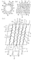
図1(a)は本発明に係るタイヤ加硫用金型の一実施形態を示す概略平面図、図1(b)は、図1(a)の分割位置非含有ブロック形成部の金型内面部の概略平面図、図1(c)は、図1(a)の分割位置含有ブロック形成部の金型内面部の概略平面図である。
【0010】
図1において、Mは分割モールド、Rは金型の周方向、D(破線)は分割モールドの分割位置、MPは分割モールドの分割片、1はタイヤブロック部に対応する金型内面部、2はタイヤブロック部に対応する金型内面部の金型周方向ライン、Bはタイヤサイプ形成用ナイフブレード、Sは隣り合う2本のナイフブレードライン4とタイヤブロック部に対応する金型内面部の金型周方向ライン2、2とで囲まれた面積、3は金型の幅方向に平行な直線(破線)、43はタイヤサイプ形成用ナイフブレードの長さ方向に沿った直線(破線)、4はナイフブレードラインで、直線部41と曲線部42とから構成されている。
なお、S1、S3は分割位置D寄りの1本のナイフブレードライン4と該分割位置D寄りの1本のナイフブレードラインの隣りの1本のナイフブレードライン4及び該ブロックを形成するために金型内面に設けられた凹部の2本の金型周方向ライン2、2とで囲まれた面積、
S2は分割位置D寄りで前記分割位置Dを挟んで隣り合う2本のナイフブレードライン4、4と該ブロックを形成するために金型内面に設けられた凹部の2本の金型周方向ライン2、2とで囲まれた面積、
SAは上記以外で隣り合う2本のナイフブレードラインと該ブロックを形成するために金型内面に設けられた凹部の2本の金型周方向ラインとで囲まれた面積である。
SBは前記ブロックを形成するために金型内面に設けられた凹部内に分割位置を有しない分割位置非含有ブロック形成部において、隣り合う2本のナイフブレードラインと該ブロックを形成するために金型内面に設けられた凹部の2本の金型周方向ラインとで囲まれた面積である。
図1(c)に示すタイヤブロック部に対応する金型内面部1の分割位置含有ブロック形成部においては、タイヤサイプ形成用ナイフブレードB1、B2、B3、B4、B5の長さ方向に沿った直線431、432、433、434、435と金型の幅方向に平行な直線3との交差角度はそれぞれ、θ1、θ2、θ2、θ1、θ1である。
【0011】
本実施形態の分割モールドのタイヤブロック部に対応する金型内面部1の分割位置非含有ブロック形成部では、図1(b)に示すようにタイヤサイプ形成用ナイフブレードB1〜B5の全てのナイフブレードは同一形状で前記直線43と金型の幅方向に平行な直線3との交差角度も全て同一角度θ11で配されている。これに対して、タイヤブロック部に対応する金型内面部1の分割位置含有ブロック形成部では、図1(c)に示すようにタイヤサイプ形成用ナイフブレードB1〜B5の全てのナイフブレードは略同一形状をしているが、前記直線431、432、433、434、435と金型の幅方向に平行な直線3との交差角度は、それぞれ、θ1、θ2、θ2、θ1、θ1の交差角度で配されていて、前記分割位置Dの隣りのタイヤサイプ形成用ナイフブレードB2、B3と金型の幅方向に平行な直線3との交差角度θ2、θ2は前記分割位置Dに隣り合っていないタイヤサイプ形成用ナイフブレードB1、B4、B5と金型の幅方向に平行な直線3との交差角度θ1よりも小さい角度となっている。
また、タイヤサイプ形成用ナイフブレードB2と金型周方向ライン2との交点71から前記分割位置Dと金型周方向ライン2との交点81の金型周方向ライン2に沿った間隔は0.5mmでタイヤサイプ形成用ナイフブレードB3と金型周方向ライン2との交点72から前記分割位置Dと金型周方向ライン2との交点82の金型周方向ライン2に沿った間隔は0.5mmである。
なお、本実施形態のナイフブレードの幅は0.3mm、深さは全長に亘り7.0mmである。
【0012】
さらに、本実施形態では、隣り合う2本のナイフブレードライン4、4とタイヤブロック部に対応する金型内面部の金型周方向ライン2とで囲まれた面積Sは、分割位置非含有ブロック形成部では、図1(b)に示すように全てSBで、同一であるが、分割位置含有ブロック形成部では、図1(c)に示すように異なっていて、SAを100としたとき、S1は94、S2は112、S3は94である。なお、分割位置非含有ブロック形成部のSBは分割位置含有ブロック形成部のSAと同じ面積である。
【0013】
本発明において、前記サイプ形成用ナイフブレードBを分割モールドの前記分割位置Dから2mm未満の位置に配した場合、サイプ形成用ナイフブレードBの分割モールドの前記分割位置D近辺の部分がタイヤ加硫工程で使用中に損傷を受けやすいので、避けることが望ましい。
【0014】
また、タイヤブロック部に対応する金型内面部1の分割位置含有ブロック形成部において、S1、S2、S3が0.7SA〜1.3SAの範囲を外れると、隣り合う2本のナイフブレードラインと該ブロックを形成するために金型内面に設けられた凹部の2本の金型周方向ラインとで囲まれたS1、S2、S3、SAに該当する領域のタイヤのブロック間の剛性差が大となり、タイヤでの偏摩耗が生じやすい。
なお、前記ブロックを形成するために金型内面に設けられた凹部内に分割位置を有する分割位置含有ブロック形成部において、前記サイプを形成するために金型内面に設けられたナイフブレードが前記分割位置を跨らないように配すると共に、隣り合う2本のナイフブレードライン4とタイヤブロック部に対応する金型内面部の金型周方向ライン2、2とで囲まれた面積Sを調整するには、タイヤサイプ形成用ナイフブレードB1、B2、B3、B4、B5の長さ方向に沿った直線431、432、433、434、435と金型の幅方向に平行な直線3との交差角度を変更することによって行う。
【0015】
なお、図1では、ナイフブレードライン4がタイヤブロック部に対応する金型内面部の金型周方向ライン2に連通しているが、ナイフブレードライン4がタイヤブロック部に対応する金型内面部の金型周方向ライン2に連通せず、金型周方向ライン2に達していない場合、前記Sに替え図2に示すように隣り合う2本のナイフブレードライン4、4と該ブロックを形成するために金型内面に設けられた凹部の2本の金型周方向ライン2、2に平行な直線22とで囲まれた面積をSとする。
【0016】
【実施例】
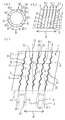
次に、実施例として、図3に示す金型内面部(ナイフブレードは後述)を有し、タイヤブロック部に対応する金型内面部の概略平面図が図1(b)、(c)の本発明に係る分割モールドM1と比較例1として、図3に示す金型内面部(ナイフブレードは後述)を有し、タイヤブロック部に対応する金型内面部の概略平面図が図4(b)、(c)に示す分割モールドM2、比較例2として、図3に示す金型内面部(ナイフブレードは後述)を有し、タイヤブロック部に対応する金型内面部の概略平面図が図5(b)、(c)に示す分割モールドM3とを用いてタイヤサイズ185/70R14のタイヤを加硫製造した。なお、実施例、比較例ともに8分割の分割モールドのものを使用した。
図3において、Rは金型の周方向、Dは分割モールドの分割位置、MPは分割モールドの分割片、1はタイヤブロック部に対応する金型内面部、2はタイヤブロック部に対応する金型内面部の金型周方向ラインで、金型周方向4列ともに同じナイフブレードを配した。
【0017】
金型の評価は、金型耐久性とタイヤ耐偏摩耗性を次の方法で実施した。
金型耐久性は、1万回加硫後のナイフブレードの変形量の逆数で、比較例1を100として指数表示した。数値が大きい程、良好である。
タイヤ耐偏摩耗性は、乾燥路を8000km走行後、金型分割位置での摩耗量の逆数を採り、比較例を100として指数表示した。数値が大きい程、良好である。
【0018】
表1は、これらの評価結果を示している。
【0019】
【表1】

表1から、本発明に係る実施例の金型は比較例1の金型と比べて、金型耐久性、タイヤ耐偏摩耗性能が改善されいる。また、比較例2の金型と比べて、タイヤ耐偏摩耗性が優れていることが認められる。
【0021】
【発明の効果】
本発明のタイヤ加硫製造用金型は、タイヤ周方向踏面部に周期性をもって繰り返し配列された各ブロックに、タイヤ幅方向に平行な直線に対して傾斜角を有すると共にタイヤ幅方向に延びる複数のサイプを一定間隔ごとに形成する複数のナイフブレードが金型内面のブロック形成部に取り付けられた分割モールド型のタイヤ加硫用金型において、
上記金型のブロック形成部のうち、金型幅方向にほぼ平行に延びる金型分割位置を備えた分割位置含有ブロック形成部では、
当該分割位置含有ブロック形成部以外のブロック形成部に形成された傾斜角θ11と同一乃至略同一の傾斜角θ1を有する複数のナイフブレードが取り付けられており、
前記傾斜角θ1では前記金型分割位置を跨るナイフブレードについては、当該ナイフブレードの前記分割位置に近い側を前記分割位置から離すことによって、前記金型分割位置を跨らない傾斜角θ2を有したナイフブレードが取り付けられている構成としたことによって、タイヤ加硫用分割モールドを用いてタイヤ偏摩耗を発生することなしに、タイヤの排水性、制動性、旋回性、耐摩耗性などを低下させることなくタイヤに本来必要な機能が充分発揮出来る形状のサイプをタイヤに配することができるとともに、前記サイプ形成用ナイフブレードのタイヤ加硫時損傷を防止することができる。
【図面の簡単な説明】
【図1】(a)本発明に係るタイヤ加硫用金型の一実施形態を示す概略平面図である。
(b)本発明に係るタイヤ加硫用金型図1(a)の分割位置非含有ブロック形成部の金型内面部の概略平面図である。
(c)本発明に係るタイヤ加硫用金型図1(a)の分割位置含有ブロック形成部の金型内面部の概略平面図である。
【図2】本発明に係る他のタイヤ加硫用金型の分割位置含有ブロック形成部の金型内面部の概略平面図である。
【図3】タイヤ踏面部に対応する加硫用金型内面の周方向概略部分平面図である。
【図4】(a)従来技術のタイヤ加硫用金型の概略平面図である。
(b)従来技術のタイヤ加硫用金型の分割位置非含有ブロック形成部の金型内面部の概略平面図である。
(c)従来技術のタイヤ加硫用金型の分割位置含有ブロック形成部の金型内面部の概略平面図である。
【図5】(a)従来技術のタイヤ加硫用金型の概略平面図である。
(b)従来技術のタイヤ加硫用金型の分割位置非含有ブロック形成部の金型内面部の概略平面図である。
(c)従来技術のタイヤ加硫用金型の分割位置含有ブロック形成部の金型内面部の概略平面図である。
【符号の説明】
1 金型内面部
2 金型内面部の金型周方向ライン
3 金型の幅方向に平行な直線
4 ナイフブレードライン
B ナイフブレード[0001]
BACKGROUND OF THE INVENTION
The present invention relates to a tire vulcanization mold, and more particularly, the mold is a split mold, and without affecting the drainage performance, braking performance, turning performance, wear resistance, etc. of the product tire. The present invention relates to a tire vulcanization mold for preventing damage and a tire vulcanized by the mold.
[0002]
[Prior art]
As a mold for vulcanizing the tire, as shown in a schematic plan view in FIG. 4 (a), the mold is perpendicular to the circumferential direction R of the mold corresponding to the tire circumferential direction of the tire vulcanization mold. A divided mold obtained by dividing the circumferential direction R of the mold is used. In addition, the broken line D of Fig.4 (a) is a division | segmentation position of the metal mold | die for tire vulcanization.
The split mold is usually divided into two parts at the upper and lower sides of the tire equator line, and the upper and lower molds are divided into about 7 to 11 split mold pieces at right angles to the circumferential direction of the mold. ing. In the example shown in FIG. 4 (a), it is divided into eight mold pieces MP1 to MP8, and a gap of about 1 to 2 mm between the adjacent mold pieces is contained in the unvulcanized tire. It fulfills its function.
[0003]
[Problems to be solved by the invention]
The tire tread surface portion is provided with a thin notch so-called sipe recess for satisfying required characteristics such as braking performance, drainage performance, and turning performance of the tire. Therefore, a sipe-forming knife blade for a tire is disposed on the inner surface of the mold at a position corresponding to the recess in order to form the recess, substantially inward of the mold inner surface, inward of the mold radial direction. . In general, the knife blade has a thickness of 0.2 mm to 1 mm, a height of 1 mm to 10 mm, a length of about 3 mm to 4 mm, and is generally made of stainless steel.
[0004]
FIG. 4B shows an outline of the mold
[0005]
When a tire is vulcanized by a mold having a knife blade having the above-described configuration, damage to the mold knife blade portion can be avoided, but a sipe having a shape in which a part of the sipe having an originally required shape is missing. Is placed on the tire. As a result, the sipe function originally required from the viewpoints of drainage, braking performance, turning performance, wear resistance, etc. cannot be sufficiently exhibited. Tire performance such as braking performance, braking performance, turning performance, and wear resistance cannot be sufficiently exhibited, and uneven wear of the tread portion occurs.
[0006]
An object of the present invention is to provide a sipe having a shape that can sufficiently perform the functions originally required for a tire without reducing the drainability, braking performance, turning performance, wear resistance, etc. of the tire using a split mold for tire vulcanization. And providing a split mold that can prevent damage to the sipe forming knife blade during tire vulcanization.
[0007]
[Means for Solving the Problems]
In order to solve the above problems, a tire vulcanization mold according to
A plurality of knives that form, at regular intervals, a plurality of sipes that have an inclination angle with respect to a straight line parallel to the tire width direction and that extend in the tire width direction on each block that is repeatedly arranged with periodicity on the tire tread surface portion. In the mold for tire vulcanization of the split mold type in which the blade is attached to the block forming part on the inner surface of the mold,
Among the block forming portions of the mold, in the divided position-containing block forming portion provided with the mold dividing position extending substantially parallel to the mold width direction,
A plurality of knife blades having an inclination angle θ1 that is the same as or substantially the same as the inclination angle θ11 formed in the block forming part other than the divided position-containing block forming part is attached,
The knife blade straddling the mold dividing position at the inclination angle θ1 has an inclination angle θ2 that does not straddle the mold dividing position by separating the side close to the dividing position of the knife blade from the dividing position. The tire vulcanization mold is provided with a knife blade attached thereto.
Here, the “inclination angle” means an intersection angle between “a straight line along the length direction of the knife blade line (line drawn by the knife blade)” and “a straight line parallel to the width direction of the mold”. .
The fact that a knife blade having an inclination angle θ2 that does not straddle the mold dividing position is attached means that the two knife blades that do not straddle the adjacent mold dividing position are located at the mold dividing position. In the case of having the inclination angle θ2, one may be the inclination angle θ2, and the remaining one may be the inclination angle θ3 (smaller than the inclination angle θ1).
The tire vulcanization mold according to
In the division position-containing block forming section,
An area surrounded by two knife blade lines adjacent to each other with the division position close to the division position and two mold circumferential lines of a recess provided on the inner surface of the mold to form the block. S2,
One knife blade line near the division position, one knife blade line adjacent to the one knife blade line near the division position, and two recesses provided on the inner surface of the mold to form the block S1, S3, and the area surrounded by the mold circumferential line of
Other than the above, the area surrounded by two knife blade lines adjacent to each other and the two mold circumferential lines of the recess provided on the inner surface of the mold to form the block is SA,
In the divided position non-containing block forming part that does not have the mold dividing position in the recess provided on the inner surface of the mold to form the block,
SB represents an area surrounded by two adjacent knife blade lines and two mold circumferential lines of a recess provided on the inner surface of the mold to form the block.
If
SA = SB,
Two knives that are adjacent to each other with the division position close to the division position, wherein the knife blade is arranged so that S1, S2, and S3 are in a range of 0.7 SA to 1.3 SA The knife blade is arranged so that S1, S2, and S3 are in the range of 0.7 SA to 1.3 SA by changing the inclination angle of the blade line. In this case, the inclination angle is close to the dividing position, and two knife blade lines adjacent to each other with the dividing position interposed therebetween are different from the inclination angles of the knife blade lines other than the two knife blade lines, and the division of the knife blade is performed. The side close to the position is separated from the division position.
The tire according to
Among the above blocks, in the division position-containing block having a mold division position extending substantially parallel to the tire width direction,
A plurality of sipes having an inclination angle θ1 that is the same or substantially the same as the inclination angle θ11 formed in the blocks other than the division position-containing block are arranged,
For a sipe that straddles the mold dividing position at the inclination angle θ1, a sipe having an inclination angle θ2 that does not straddle the mold dividing position by separating the side of the sipe closer to the dividing position from the dividing position. Is a tire characterized by being arranged.
Here, the “inclination angle” means an intersection angle between the “straight line along the sipe length direction” and the “straight line along the tire width direction”, and the tire according to
The tire according to
TS1, TS3, and the area surrounded by one sipe near the dividing position, one sipe adjacent to the one sipe near the dividing position, and two circumferential lines at the end of the block
Other than the above, the area surrounded by two adjacent sipes and the two circumferential lines at the end of the block is TSA,
TSB represents an area surrounded by two adjacent sipes of blocks other than the division position-containing block and two circumferential lines at the end of the block.
If
TSA = TSB,
There is a pneumatic tire in which sipes are formed so that TS1, TS2, and TS3 are in a range of 0.7TSA to 1.3TSA.
[0008]
In the tire vulcanizing mold according to the present invention, the individual knife blades provided on the inner surface of the mold are arranged as described above in order to form a tire sipe, so that the vulcanized tire is removed from the vulcanizing mold. In this case, even if each split mold piece moves radially outward from the center of the tire vulcanization mold to the outer side of the outer diameter of the mold, a force such as twisting acts on the knife blade of the split part when it is removed from the tire. Distortion is unlikely to occur and difficult to damage.
In addition, since each knife blade can secure the shape for forming the sipe shape that is originally required for the tire required characteristics, the tire vulcanized and manufactured by the tire vulcanizing mold according to the present invention has a drainage and braking performance. Performance, turning ability, wear resistance and the like can be maintained.
[0009]
DETAILED DESCRIPTION OF THE INVENTION
FIG. 1A is a schematic plan view showing an embodiment of a tire vulcanizing mold according to the present invention, and FIG. 1B is an inner surface of the mold of the block position-free block forming portion of FIG. FIG. 1C is a schematic plan view of the inner surface of the mold of the divided position-containing block forming unit in FIG.
[0010]
In FIG. 1, M is a divided mold, R is a circumferential direction of the mold, D (broken line) is a divided position of the divided mold, MP is a divided piece of the divided mold, 1 is an inner surface of the mold corresponding to the tire block portion, 2 Is a mold circumferential line on the inner surface of the mold corresponding to the tire block portion, B is a knife blade for forming a tire sipe, S is a mold on the inner surface of the mold corresponding to two adjacent
S1 and S3 are one
S2 is two mold circumferential lines of a recess provided on the inner surface of the mold in order to form the two
SA is an area surrounded by two knife blade lines adjacent to each other and two mold circumferential lines of a recess provided on the inner surface of the mold to form the block.
In order to form the block, the SB forms a block for forming the block with two adjacent knife blade lines in a block forming section that does not have a dividing position in a recess provided in the inner surface of the mold. It is an area surrounded by two mold circumferential direction lines of a recess provided on the inner surface of the mold.
In the split position-containing block forming portion of the mold
[0011]
In the split position non-containing block forming portion of the mold
Further, the distance along the
In addition, the width | variety of the knife blade of this embodiment is 0.3 mm, and depth is 7.0 mm over the full length.
[0012]
Further, in the present embodiment, the area S surrounded by the two adjacent
[0013]
In the present invention, when the sipe forming knife blade B is disposed at a position less than 2 mm from the dividing position D of the split mold, the portion near the dividing position D of the split mold of the sipe forming knife blade B is tire vulcanized. It is desirable to avoid it because it is susceptible to damage during use in the process.
[0014]
Further, in the divided position-containing block forming portion of the mold
In the split position-containing block forming portion having a split position in a recess provided on the inner surface of the mold for forming the block, a knife blade provided on the inner surface of the mold for forming the sipe is divided. The area S surrounded by the two adjacent
[0015]
In FIG. 1, the
[0016]
【Example】
Next, as an example, a schematic plan view of the mold inner surface corresponding to the tire block portion is shown in FIGS. 1B and 1C. As the split mold M1 according to the present invention and Comparative Example 1, a schematic plan view of the mold inner surface portion corresponding to the tire block portion is shown in FIG. 3) As a split mold M2 shown in (c) and Comparative Example 2, a schematic plan view of the mold inner surface portion corresponding to the tire block portion has the mold inner surface portion (knife blade will be described later) shown in FIG. A tire having a tire size of 185 / 70R14 was vulcanized and produced using the divided mold M3 shown in 5 (b) and (c). In the examples and comparative examples, an 8-part split mold was used.
In FIG. 3, R is the circumferential direction of the mold, D is the division position of the divided mold, MP is the divided piece of the divided mold, 1 is the inner surface of the mold corresponding to the tire block portion, and 2 is the metal corresponding to the tire block portion. The same knife blade was arranged in the mold circumferential direction line on the inner surface of the mold in all four rows in the mold circumferential direction.
[0017]
Evaluation of the mold was carried out by the following methods for mold durability and tire uneven wear resistance.
The mold durability was the reciprocal of the deformation amount of the knife blade after 10,000 times of vulcanization, and the index was displayed with Comparative Example 1 as 100. The larger the value, the better.
The tire uneven wear resistance was expressed as an index with the comparative example being 100, taking the reciprocal of the wear amount at the mold division position after running 8000 km on the dry road. The larger the value, the better.
[0018]
Table 1 shows the evaluation results.
[0019]
[Table 1]
From Table 1, the mold of the example according to the present invention has improved mold durability and resistance to uneven wear of the tire as compared with the mold of Comparative Example 1. Further, it is recognized that the uneven wear resistance of the tire is excellent as compared with the mold of Comparative Example 2.
[0021]
【The invention's effect】
The tire vulcanization manufacturing mold according to the present invention includes a plurality of blocks that are repeatedly arranged with periodicity on the tire circumferential direction tread portion, and each have an inclination angle with respect to a straight line parallel to the tire width direction, and extends in the tire width direction. In the mold for tire vulcanization of a split mold type, in which a plurality of knife blades that form the sipe at regular intervals are attached to the block forming portion on the inner surface of the mold,
Among the block forming portions of the mold, in the divided position-containing block forming portion provided with the mold dividing position extending substantially parallel to the mold width direction,
A plurality of knife blades having an inclination angle θ1 that is the same as or substantially the same as the inclination angle θ11 formed in the block forming part other than the divided position-containing block forming part is attached,
The knife blade straddling the mold dividing position at the inclination angle θ1 has an inclination angle θ2 that does not straddle the mold dividing position by separating the side close to the dividing position of the knife blade from the dividing position. By using a configuration with a knife blade attached, the tire drainability, braking performance, turning performance, wear resistance, etc. are reduced without causing uneven tire wear using a split mold for tire vulcanization. Thus, a sipe having a shape that can sufficiently perform the functions originally required for the tire can be disposed on the tire, and damage to the sipe forming knife blade during tire vulcanization can be prevented.
[Brief description of the drawings]
FIG. 1 (a) is a schematic plan view showing an embodiment of a tire vulcanization mold according to the present invention.
(B) Tire vulcanizing mold according to the present invention is a schematic plan view of the inner surface of the mold of the block position-free block forming section in FIG. 1 (a).
(C) Tire vulcanizing mold according to the present invention is a schematic plan view of a mold inner surface portion of a divided position-containing block forming portion in FIG. 1 (a).
FIG. 2 is a schematic plan view of a mold inner surface portion of a divided position-containing block forming portion of another tire vulcanizing mold according to the present invention.
FIG. 3 is a schematic partial plan view in the circumferential direction of an inner surface of a vulcanizing mold corresponding to a tire tread surface portion.
FIG. 4 (a) is a schematic plan view of a conventional tire vulcanization mold.
(B) It is a schematic top view of the metal mold | die inner surface part of the division position non-containing block formation part of the metal mold | die for tire vulcanization | cure of a prior art.
(C) It is a schematic top view of the metal mold | die inner surface part of the division position containing block formation part of the metal mold | die for tire vulcanization | cure of a prior art.
5A is a schematic plan view of a conventional tire vulcanization mold. FIG.
(B) It is a schematic top view of the metal mold | die inner surface part of the division position non-containing block formation part of the metal mold | die for tire vulcanization | cure of a prior art.
(C) It is a schematic top view of the metal mold | die inner surface part of the division position containing block formation part of the metal mold | die for tire vulcanization | cure of a prior art.
[Explanation of symbols]
DESCRIPTION OF
Claims (4)
上記金型のブロック形成部のうち、金型幅方向にほぼ平行に延びる金型分割位置を備えた分割位置含有ブロック形成部では、
当該分割位置含有ブロック形成部以外のブロック形成部に形成された傾斜角θ11と同一乃至略同一の傾斜角θ1を有する複数のナイフブレードが取り付けられており、
前記傾斜角θ1では前記金型分割位置を跨るナイフブレードについては、当該ナイフブレードの前記分割位置に近い側を前記分割位置から離すことによって、前記金型分割位置を跨らない傾斜角θ2を有したナイフブレードが取り付けられていることを特徴とするタイヤ加硫用金型。A plurality of knives that form, at regular intervals, a plurality of sipes that have an inclination angle with respect to a straight line parallel to the tire width direction and that extend in the tire width direction on each block that is repeatedly arranged with periodicity on the tire tread surface portion. In the mold for tire vulcanization of the split mold type in which the blade is attached to the block forming part on the inner surface of the mold,
Among the block forming portions of the mold, in the divided position-containing block forming portion provided with the mold dividing position extending substantially parallel to the mold width direction,
A plurality of knife blades having an inclination angle θ1 that is the same as or substantially the same as the inclination angle θ11 formed in the block forming part other than the divided position-containing block forming part is attached,
The knife blade straddling the mold dividing position at the inclination angle θ1 has an inclination angle θ2 that does not straddle the mold dividing position by separating the side close to the dividing position of the knife blade from the dividing position. A tire vulcanizing mold, wherein a knife blade is attached.
分割位置寄りで前記分割位置を挟んで隣り合う2本のナイフブレードラインと該ブロックを形成するために金型内面に設けられた凹部の2本の金型周方向ラインとで囲まれた面積をS2、
分割位置寄りの1本のナイフブレードライン、該分割位置寄りの1本のナイフブレードラインの隣りの1本のナイフブレードライン及び該ブロックを形成するために金型内面に設けられた凹部の2本の金型周方向ラインとで囲まれた面積をS1、S3、
上記以外で隣り合う2本のナイフブレードラインと該ブロックを形成するために金型内面に設けられた凹部の2本の金型周方向ラインとで囲まれた面積をSA、前記ブロックを形成するために金型内面に設けられた凹部内に金型分割位置を有しない分割位置非含有ブロック形成部において、
隣り合う2本のナイフブレードラインと該ブロックを形成するために金型内面に設けられた凹部の2本の金型周方向ラインとで囲まれた面積をSB、
とした場合、
SA=SB、
S1、S2、S3が0.7SA〜1.3SAの範囲となるようにナイフブレードを配する請求項1記載のタイヤ加硫用金型。In the division position-containing block forming section,
An area surrounded by two knife blade lines adjacent to each other with the division position close to the division position and two mold circumferential lines of a recess provided on the inner surface of the mold to form the block. S2,
One knife blade line near the division position, one knife blade line adjacent to the one knife blade line near the division position, and two recesses provided on the inner surface of the mold to form the block S1, S3, and the area surrounded by the mold circumferential line of
Other than the above, the area surrounded by two adjacent knife blade lines and the two mold circumferential lines of the recess provided on the inner surface of the mold to form the block is SA, and the block is formed. Therefore, in the division position non-containing block forming portion that does not have a mold division position in the recess provided on the inner surface of the mold,
SB represents an area surrounded by two adjacent knife blade lines and two mold circumferential lines of a recess provided on the inner surface of the mold to form the block.
If
SA = SB,
The tire vulcanization mold according to claim 1, wherein the knife blade is arranged so that S1, S2, and S3 are in a range of 0.7 SA to 1.3 SA.
上記ブロックのうち、タイヤ幅方向にほぼ平行に延びる金型分割位置を有する分割位置含有ブロックでは、
当該分割位置含有ブロック以外のブロックに形成された傾斜角θ11と同一乃至略同一の傾斜角θ1を有する複数のサイプが配されており、
前記傾斜角θ1では前記金型分割位置を跨るサイプについては、当該サイプの前記分割位置に近い側を前記分割位置から離すことによって、前記金型分割位置を跨らない傾斜角θ2を有したサイプが配されていることを特徴とするタイヤ
。A pneumatic structure in which a plurality of sipes having an inclination angle with respect to a straight line parallel to the tire width direction and a plurality of sipes extending in the tire width direction are formed at regular intervals on each block repeatedly arranged with periodicity on the tire tread surface portion. In the tire,
Among the above blocks, in the division position-containing block having a mold division position extending substantially parallel to the tire width direction,
A plurality of sipes having an inclination angle θ1 that is the same or substantially the same as the inclination angle θ11 formed in the blocks other than the division position-containing block are arranged,
For a sipe that straddles the mold dividing position at the inclination angle θ1, a sipe having an inclination angle θ2 that does not straddle the mold dividing position by separating the side of the sipe closer to the dividing position from the dividing position. A tire characterized by being arranged.
分割位置寄りで前記分割位置を挟んで隣り合う2本のサイプと該ブロック端部の2本の周方向ラインとで囲まれた面積をTS2、
分割位置寄りの1本のサイプ、該分割位置寄りの1本のサイプの隣りの1本のサイプ及び該ブロック端部の2本の周方向ラインとで囲まれた面積をTS1、TS3、
上記以外で隣り合う2本のサイプと該ブロック端部の2本の周方向ラインとで囲まれた面積をTSA、
前記分割位置含有ブロック以外のブロックの
隣り合う2本のサイプと該ブロック端部の2本の周方向ラインとで囲まれた面積をTSB、
とした場合、
TSA=TSB、
TS1、TS2、TS3が0.7TSA〜1.3TSAの範囲となるようにサイプが形成されている請求項3記載の空気入りタイヤ。TS2 represents an area surrounded by two sipes adjacent to each other with the division position between the division position-containing blocks and two circumferential lines at the end of the block.
TS1, TS3, and the area surrounded by one sipe near the dividing position, one sipe adjacent to the one sipe near the dividing position, and two circumferential lines at the end of the block
Other than the above, the area surrounded by two adjacent sipes and the two circumferential lines at the end of the block is TSA,
TSB represents an area surrounded by two adjacent sipes of blocks other than the division position-containing block and two circumferential lines at the end of the block.
If
TSA = TSB,
The pneumatic tire according to claim 3, wherein sipes are formed so that TS1, TS2, and TS3 are in a range of 0.7TSA to 1.3TSA.
Priority Applications (1)
| Application Number | Priority Date | Filing Date | Title |
|---|---|---|---|
| JP2001104775A JP3925836B2 (en) | 2001-04-03 | 2001-04-03 | Tire vulcanizing mold and tire vulcanized by the mold |
Applications Claiming Priority (1)
| Application Number | Priority Date | Filing Date | Title |
|---|---|---|---|
| JP2001104775A JP3925836B2 (en) | 2001-04-03 | 2001-04-03 | Tire vulcanizing mold and tire vulcanized by the mold |
Publications (2)
| Publication Number | Publication Date |
|---|---|
| JP2002292640A JP2002292640A (en) | 2002-10-09 |
| JP3925836B2 true JP3925836B2 (en) | 2007-06-06 |
Family
ID=18957586
Family Applications (1)
| Application Number | Title | Priority Date | Filing Date |
|---|---|---|---|
| JP2001104775A Expired - Lifetime JP3925836B2 (en) | 2001-04-03 | 2001-04-03 | Tire vulcanizing mold and tire vulcanized by the mold |
Country Status (1)
| Country | Link |
|---|---|
| JP (1) | JP3925836B2 (en) |
Cited By (1)
| Publication number | Priority date | Publication date | Assignee | Title |
|---|---|---|---|---|
| CN104442215B (en) * | 2013-09-24 | 2017-07-18 | 住友橡胶工业株式会社 | Pneumatic tire |
Families Citing this family (4)
| Publication number | Priority date | Publication date | Assignee | Title |
|---|---|---|---|---|
| MX2011003482A (en) * | 2008-10-03 | 2011-04-28 | Michelin Rech Tech | Undulated progressive tire mold element. |
| JP7115144B2 (en) * | 2018-08-29 | 2022-08-09 | 横浜ゴム株式会社 | pneumatic tire |
| JP7115248B2 (en) * | 2018-11-26 | 2022-08-09 | 横浜ゴム株式会社 | pneumatic tire |
| JP7419742B2 (en) * | 2019-10-15 | 2024-01-23 | 住友ゴム工業株式会社 | Vulcanization mold for heavy-duty tires and manufacturing method for heavy-duty tires |
-
2001
- 2001-04-03 JP JP2001104775A patent/JP3925836B2/en not_active Expired - Lifetime
Cited By (1)
| Publication number | Priority date | Publication date | Assignee | Title |
|---|---|---|---|---|
| CN104442215B (en) * | 2013-09-24 | 2017-07-18 | 住友橡胶工业株式会社 | Pneumatic tire |
Also Published As
| Publication number | Publication date |
|---|---|
| JP2002292640A (en) | 2002-10-09 |
Similar Documents
| Publication | Publication Date | Title |
|---|---|---|
| CN101808836B (en) | Tread for tyre including gum blocks with notches | |
| JP3226968B2 (en) | Pneumatic tire | |
| JP2008007102A (en) | Tire with tread having sipes, and sipe blade for tire | |
| JP5820274B2 (en) | Tire tread | |
| JP3308245B2 (en) | Pneumatic tire | |
| EP2450200A1 (en) | Pneumatic tire | |
| CN104417276A (en) | Pneumatic tire tread with sipes and mold blade | |
| JP5702433B2 (en) | Tire molding mold and tire | |
| JP3925836B2 (en) | Tire vulcanizing mold and tire vulcanized by the mold | |
| JP2007045239A (en) | Pneumatic tire, its manufacturing method and tire vulcanization metal die used for it | |
| JP6909082B2 (en) | Tire vulcanization mold | |
| JPS59169836A (en) | Manufacture of tire | |
| US20220194037A1 (en) | Mold segment irregular wear and noise countermeasure | |
| JP6612604B2 (en) | Pneumatic tire | |
| JP4726106B2 (en) | Pneumatic tire | |
| JPS63141806A (en) | Pneumatic tire | |
| JP4312528B2 (en) | Pneumatic tire, tire vulcanization mold, and method for manufacturing pneumatic tire | |
| JP2004210043A (en) | Pneumatic tire | |
| JPH09277805A (en) | Pneumatic tire and sipe forming portion structure | |
| JPS6218305A (en) | Manufacture or tire | |
| JP7081177B2 (en) | Tire mold | |
| JPS62242508A (en) | Manufacture of pneumatic tire for heavy load | |
| JPH0234409A (en) | Pneumatic tire and its die for vulcanization molding | |
| JPH09323510A (en) | Pneumatic tire | |
| JP4707849B2 (en) | Pneumatic tire and method for manufacturing pneumatic tire |
Legal Events
| Date | Code | Title | Description |
|---|---|---|---|
| A621 | Written request for application examination |
Free format text: JAPANESE INTERMEDIATE CODE: A621 Effective date: 20040610 |
|
| A977 | Report on retrieval |
Free format text: JAPANESE INTERMEDIATE CODE: A971007 Effective date: 20060210 |
|
| TRDD | Decision of grant or rejection written | ||
| A01 | Written decision to grant a patent or to grant a registration (utility model) |
Free format text: JAPANESE INTERMEDIATE CODE: A01 Effective date: 20070222 |
|
| A61 | First payment of annual fees (during grant procedure) |
Free format text: JAPANESE INTERMEDIATE CODE: A61 Effective date: 20070223 |
|
| R150 | Certificate of patent or registration of utility model |
Free format text: JAPANESE INTERMEDIATE CODE: R150 Ref document number: 3925836 Country of ref document: JP Free format text: JAPANESE INTERMEDIATE CODE: R150 |
|
| FPAY | Renewal fee payment (event date is renewal date of database) |
Free format text: PAYMENT UNTIL: 20100309 Year of fee payment: 3 |
|
| FPAY | Renewal fee payment (event date is renewal date of database) |
Free format text: PAYMENT UNTIL: 20130309 Year of fee payment: 6 |
|
| R250 | Receipt of annual fees |
Free format text: JAPANESE INTERMEDIATE CODE: R250 |
|
| FPAY | Renewal fee payment (event date is renewal date of database) |
Free format text: PAYMENT UNTIL: 20160309 Year of fee payment: 9 |
|
| R250 | Receipt of annual fees |
Free format text: JAPANESE INTERMEDIATE CODE: R250 |
|
| R250 | Receipt of annual fees |
Free format text: JAPANESE INTERMEDIATE CODE: R250 |
|
| S531 | Written request for registration of change of domicile |
Free format text: JAPANESE INTERMEDIATE CODE: R313531 |
|
| R350 | Written notification of registration of transfer |
Free format text: JAPANESE INTERMEDIATE CODE: R350 |
|
| S533 | Written request for registration of change of name |
Free format text: JAPANESE INTERMEDIATE CODE: R313533 |
|
| R350 | Written notification of registration of transfer |
Free format text: JAPANESE INTERMEDIATE CODE: R350 |
|
| R250 | Receipt of annual fees |
Free format text: JAPANESE INTERMEDIATE CODE: R250 |
|
| R250 | Receipt of annual fees |
Free format text: JAPANESE INTERMEDIATE CODE: R250 |
|
| R250 | Receipt of annual fees |
Free format text: JAPANESE INTERMEDIATE CODE: R250 |
|
| EXPY | Cancellation because of completion of term |