JP3916552B2 - Oscillating sorter drive device - Google Patents
Oscillating sorter drive device Download PDFInfo
- Publication number
- JP3916552B2 JP3916552B2 JP2002331063A JP2002331063A JP3916552B2 JP 3916552 B2 JP3916552 B2 JP 3916552B2 JP 2002331063 A JP2002331063 A JP 2002331063A JP 2002331063 A JP2002331063 A JP 2002331063A JP 3916552 B2 JP3916552 B2 JP 3916552B2
- Authority
- JP
- Japan
- Prior art keywords
- crankshaft
- sorting device
- bearing
- threshing
- intermediate portion
- Prior art date
- Legal status (The legal status is an assumption and is not a legal conclusion. Google has not performed a legal analysis and makes no representation as to the accuracy of the status listed.)
- Expired - Fee Related
Links
Images


Landscapes
- Threshing Machine Elements (AREA)
- Combined Means For Separation Of Solids (AREA)
Description
【0001】
【発明の属する技術分野】
本発明は、両端部が脱穀機体に回動自在に支持されている駆動自在なクランク軸を備えている脱穀装置の揺動選別装置駆動装置に関する。
【0002】
【従来の技術】
上記揺動選別装置駆動装置において、クランク軸の両端部に対して偏芯している中間部と揺動選別装置にわたって連結されてクランク軸による揺動選別装置の揺動駆動を可能にする選別装置駆動体と、クランク軸の中間部との間にボールベアリングなどのベアリングを介装すれば、揺動選別装置の駆動がスムーズになる。このようにベアリングを介装したものとしては、従来、たとえば特許文献1に示されるものがあった。
【0003】
【特許文献1】
特開2000−287527号公報 ( 段落番号〔0023〕〜〔0026〕、図6 )
【0004】
【発明が解決しようとする課題】
上記した如くベアリングを採用したものにあっては、従来、ランク軸が中間部と端部に分割自在になっていた。すなわち、クランク軸を中間部と端部に分解することにより、ベアリングを中間部に対して抜き差して脱着できるようになっていた。このため、クランク軸の面から構造が複雑化していた。
【0005】
本発明の目的は、ベアリングで円滑に駆動できるとともにベアリングの脱着が可能でありながら構造簡単に得られる脱穀装置の揺動選別装置駆動装置を提供することにある。
【0006】
【課題を解決するための手段】
請求項1による発明の構成、作用、効果はつぎのとおりである。
【0007】
〔構成〕
両端部が脱穀機体に回動自在に支持されている駆動自在なクランク軸を備えている脱穀装置の揺動選別装置駆動装置において、前記クランク軸を、前記両端部が中間部に対して偏芯する状態に屈曲した一本の屈曲軸によって構成し、前記クランク軸の前記中間部に外嵌している支持筒、この支持筒に内側輪体が外嵌しているベアリング、このベアリングの外側輪体と揺動選別装置にわたって連結している選別装置駆動体を備えてある。
【0008】
〔作用〕
クランク軸の中間部と選別装置駆動体との間にベアリングが介在しているものだから、クランク軸と選別装置駆動体がベアリングのためにスムーズに相対回動しながら揺動選別装置が駆動される。
【0009】
クランク軸の中間部に支持筒が外嵌し、この支持筒にベアリングの内側輪体が外嵌しているものだから、内側輪体の内径がクランク軸の外径に比して大きなベアリングを採用できる。すなわち、ベアリングの内径とクランク軸の外径との差のためにクランク軸の中間部と端部の間の屈曲部を通過するベアリングを採用できる。これにより、クランク軸を一本の屈曲軸によって構成しているものでありながら、かつ、ベアリングをクランク軸に組み付けた場合、クランク軸の中間部に外嵌する支持筒のためにベアリングはクランク軸との間にガタ付きが発生しない状態で組み付くのでありながら、ベアリングをクランク軸に対してその端から嵌め込むとか抜き外すことができる。
【0010】
〔効果〕
従って、クランク軸と選別装置駆動体がベアリングによってスムーズに相対回動して揺動選別装置を円滑に駆動でき、ベアリングをクランク軸に対して脱着して修理するとか点検できる。その割には、一本の屈曲軸で成る構造簡単なクランク軸を採用して安価に得られる。
【0011】
請求項2による発明の構成、作用、効果はつぎのとおりである。
【0012】
〔構成〕
請求項1による発明の構成において、前記選別装置駆動体が前記ベアリングの前記外側輪体に外嵌しているとともに、前記選別装置駆動体を前記外側輪体に係止させる止め輪を前記外側輪体に止着してある。
【0013】
〔作用〕
止め輪をベアリングの外側輪体から取り外した状態にすると、選別装置駆動体をベアリングに嵌めるとか、ベアリングから抜き外すことができるものである。これにより、選別装置駆動体は、ベアリングに外嵌するように形成して設けた組み付け孔によってベアリングに対して連結できる。
【0014】
〔効果〕
従って、選別装置駆動体に組み付け孔を設けるだけの簡単な連結構造で選別装置駆動体とベアリングを連結でき、この面からも構造の簡略化を行なってコストダウンできる。また、止め輪を脱着するだけで操作簡単に選別装置駆動体とベアリングを連結するとか分離できる。
【0015】
【発明の実施の形態】
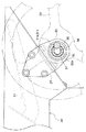
図1に示すように、脱穀機体1の横外側に駆動自在に位置する無端回動式の脱穀フィードチェーン2によって刈取り穀稈の株元側を脱穀機体1の後方に向けて挟持搬送してその刈取り穀稈の穂先側を脱穀機体内の扱室3に供給して回動する扱胴4によって脱穀処理し、脱穀排ワラを扱室3の後端部に位置する送塵口5から搬出するように脱穀部を構成してある。扱室3の受網6、及び前記送塵口5から落下した脱穀処理物を、扱室3の下方に位置する駆動揺動自在な揺動選別装置20と、この揺動選別装置20の前端部の下方に位置する唐箕7から脱穀機体後方向きに供給される選別風とによって穀粒と塵埃に選別し、穀粒を揺動選別装置20の下方に落下させ、塵埃を扱室3の後方に位置する排塵ファン8の排出口8aや、脱穀機体1の後部に位置する排塵口9から選別風と共に機体外に排出するように選別部を構成してある。選別部から落下した1番穀粒を、揺動選別装置20の下方の唐箕7の後方近くに位置する1番スクリューコンベヤ11によって脱穀機体1の横外側に搬出するように構成してある。選別部から落下した2番穀粒を、揺動選別装置20の後端部の下方に位置する2番スクリューコンベベヤ12によって脱穀機体1の横外側に搬送し、脱穀機体1の横外側で揚送装置13によって揚送して、この揚送装置13の吐出口13aから脱穀機体1の内部に放出して揺動選別装置20の始端側に還元するように構成し、もって、コンバイン用の脱穀装置を構成してある。
【0016】
前記揺動選別装置20は、シーブケース21、このシーブケース21の内部に揺動選別装置20の前後及び上下方向に並べて装着したグレンパン22、チャフシーブ23、ストローラック24、グレンシーブ25を備えて構成してある。シーブケース21の前端側を、揺動リンク26を介して脱穀機体1に前後移動自在に支持させ、後端側を、脱穀機体横向きのクランク軸31を備えた揺動選別装置駆動装置30を介して脱穀機体1に支持させてある。
これにより、揺動選別装置20は、前記揺動選別装置駆動装置30によって脱穀機体1の前後方向に揺動するように駆動され、扱室3からの脱穀処理物をグレンパン22、チャフシーブ23などの各選別体によって脱穀機体後方向きに搬送しながら穀粒と、ワラ屑などの塵埃とに選別処理し、穀粒を1番スクリューコンベヤ11や2番スクリューコンベヤ12に落下させ、塵埃を排塵口9に送出するとか選別風によって搬出させる。
【0017】
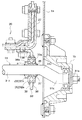
図2に示すように、前記揺動選別装置駆動装置30は、脱穀機体1の左側の横側壁1aの外面側に軸支部材を取付けて設けた支持部1bと、脱穀機体1の右側の横側壁1aの外面側に軸支部材を取付けて設けた支持部1bとにわたって軸芯Xまわりで回動自在に支持させた前記クランク軸31、このクランク軸31の前記左横側壁1aの支持部1bや前記右横側壁1aの支持部1bに連結している端部31aに対して偏芯している中間部31bの両端側に装着したボールベアリング32、クランク軸31の左端側に位置する前記ボールベアリング32の外側輪体32aと、揺動選別装置20の前記シーブケース21の左横側の角部にブラケットを取付けて設けた連結部27とにわたって連結した選別装置駆動体33、クランク軸31の右端側に位置する前記ボールベアリング32の外側輪体32aと、前記シーブケース21の右横側の角部にブラケットを取付けて設けた連結部27とにわたって連結した選別装置駆動体33を備えて構成してある。
【0018】
前記クランク軸31の前記一方の横側壁1aの支持部1bから脱穀機体横外側に突出している端部にクランク軸駆動プーリ34をキー35による係合によって一体回動するように取付けてあるとともに、このクランク軸駆動プーリ34は、前記唐箕7、1番スクリューコンベヤ11、2番スクリューコンベヤ12のそれぞれを駆動するプーリ(図示せず)に動力伝達する伝動ベルト(図示せず)が巻回されて、前記唐箕7、1番スクリューコンベヤ11、2番スクリューコンベヤ12と共に駆動されるように構成してある。
【0019】
これにより、揺動選別装置駆動装置30は、クランク軸駆動プーリ34によってクランク軸31を脱穀機体横向きの前記軸芯Xまわりで回動するように駆動し、回動するクランク軸34の中間部31bによって左右の揺動選別装置駆動体33をこれらに対して相対回転しながらボールベアリング32を介して昇降操作することにより、シーブケース21の後端側を前後方向に往復移送することによって揺動選別装置20の全体を前後方向に往復揺動するように駆動する。
【0020】
前記クランク軸31は、一方の端部が脱穀機体1の一方の横側壁1aの支持部1bに取付ける端部31aになり、他方の端部が脱穀機体1の他方の横側壁1aの支持部1bに取付ける端部31aになり、中間部が左右の選別装置駆動体33を連結する中間部31bになり、両端部が中間部に対して偏芯した状態に曲げ加工した一本の屈曲丸軸によって構成してある。
【0021】
クランク軸中間部31bの左端側に装着してある前記ボールベアリング32も、クランク軸中間部31bの右端側に装着してあるボールベアリング32も、図4などに示す如くクランク軸中間部31bに取付けた支持筒36に内側輪体32bを外嵌させることによってクランク軸中間部31bに装着してある。
【0022】
左右側いずれの支持筒36も、クランク軸31を構成している丸軸が屈曲加工する前の直線状にあるときに嵌め込むことによって、すなわち、支持筒36が外嵌した状態にある丸棒を屈曲加工してクランク軸31を作製することによってクランク軸31の中間部31bに装着し、図4の如く支持筒36の端部とクランク軸中間部31bとを溶接aで連結することによってクランク軸中間部31bの所定の組み付け位置に固定してある。
【0023】
つまり、ボールベアリング32として、図5に示す如くクランク軸31の中間部31bと端部31aの間の屈曲部31cを通過する大きさの内側輪体32bの内径Dを備えて、クランク軸31に対してこれの一端側から抜き挿しできるボールベアリングを採用してある。そして、クランク軸31の中間部31bの所定の組み付け位置に装着したボールベアリング32は、内側輪体32bの内径Dとクランク軸中間部31bの外径との寸法差が支持筒36によって吸収されてクランク軸中間部31bに対してガタ付きが発生しない状態で組み付くようになっている。
【0024】
前記左右側いずれのボールベアリング32も、図4に示す如く支持筒36の一端側に一体成形したストッパー部36aと、支持筒36の他端側に止着した止め輪37とによって支持筒36に対して脱着自在に連結してある。
すなわち、前記ストッパー部36aは、ボールベアリング32の内側輪体32bの一方の側面に対して係止してストッパー作用するようになっており、前記止め輪37は、ボールベアリング32の内側輪体32bの他方の側面に対して係止してストッパー作用するようになっている。止め輪37を取り外すことにより、ボールベアリング32を支持筒36から抜き外せるようになっている。
【0025】
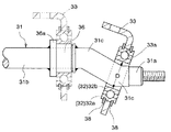
前記左右側いずれの選別装置駆動体33も、図4に示すように、選別装置駆動体33の端部に設けた組み付け孔33aによってボールベアリング32の外側輪体32aに対して外嵌させてある。選別装置駆動体33の両横側に分散するように配置してボールベアリング32の外側輪体32aに止着した一対の止め輪38が選別装置駆動体33の側面に当接して選別装置駆動体33をボールベアリング32の外側輪体32aに係止させるように構成してある。これにより、左右側いずれの選別装置駆動体33も、ボールベアリング32の外側輪体32aに対して外れないように連結している。
【0026】
〔別実施形態〕
前記ボールベアリング32に替え、ニードルベアリングなど各種の転がり式のベアリングを採用して実施してもよいのであり、これらボールベアリング32、ニードルベアリングなどを総称してベアリング32と呼称する。
【図面の簡単な説明】
【図1】コンバイン用脱穀装置の側面図
【図2】揺動選別装置駆動装置の縦断後面図
【図3】クランク軸の選別装置駆動体装着部での断面図
【図4】クランク軸と選別装置駆動体の連結構造を示す断面図
【図5】ベアリング脱着要領を示す説明図
【符号の説明】
1a 脱穀機体
20 揺動選別装置
31 クランク軸
31a クランク軸の端部
31b クランク軸の中間部
32 ベアリング
32b ベアリングの内側輪体
32a ベアリングの外側輪体
33 選別装置駆動体
36 支持筒
38 止め輪[0001]
BACKGROUND OF THE INVENTION
The present invention relates to an oscillating sorting device driving device for a threshing device having a driveable crankshaft whose both ends are rotatably supported by a threshing machine body.
[0002]
[Prior art]
In the above-mentioned swing sorting device driving device, the sorting device which is connected across the swing sorting device and the intermediate part which is eccentric with respect to both ends of the crankshaft, and enables swing drive of the swing sorting device by the crankshaft. If a bearing such as a ball bearing is interposed between the drive body and the intermediate portion of the crankshaft, the swing sorting device can be driven smoothly. Conventionally, for example,
[0003]
[Patent Document 1]
JP 2000-287527 A (paragraph numbers [0023] to [0026], FIG. 6)
[0004]
[Problems to be solved by the invention]
In the case of using the bearing as described above, the rank shaft has been conventionally divided into an intermediate portion and an end portion. That is, by disassembling the crankshaft into an intermediate portion and an end portion, the bearing can be removed from and attached to the intermediate portion. For this reason, the structure is complicated from the surface of the crankshaft.
[0005]
An object of the present invention is to provide an oscillation sorting device drive device for a threshing device that can be driven smoothly by a bearing and can be easily attached and detached while having a simple structure.
[0006]
[Means for Solving the Problems]
The configuration, operation, and effect of the invention according to
[0007]
〔Constitution〕
In a threshing apparatus swinging sorter drive device having a driveable crankshaft supported at both ends by a threshing machine body, the crankshaft is decentered with respect to an intermediate portion. A support cylinder that is formed by a single bent shaft that is bent so as to be fitted, and that is externally fitted to the intermediate portion of the crankshaft, a bearing in which an inner ring body is externally fitted to the support cylinder, and an outer ring of the bearing A sorting device driver is provided which is coupled across the body and the swing sorting device.
[0008]
[Action]
Since the bearing is interposed between the intermediate part of the crankshaft and the sorter drive body, the swing sorter is driven while the crankshaft and the sorter drive body smoothly rotate relative to each other for the bearing. .
[0009]
A support cylinder is fitted on the middle part of the crankshaft, and the inner ring body of the bearing is fitted on this support cylinder, so a bearing with a larger inner ring body diameter than the outer diameter of the crankshaft is used. it can. That is, it is possible to employ a bearing that passes through a bent portion between an intermediate portion and an end portion of the crankshaft because of the difference between the inner diameter of the bearing and the outer diameter of the crankshaft. As a result, the crankshaft is constituted by a single bent shaft, and when the bearing is assembled to the crankshaft, the bearing is attached to the crankshaft because of the support cylinder that is fitted around the middle portion of the crankshaft. The bearing can be fitted or removed from its end with respect to the crankshaft while being assembled in a state where there is no backlash between the bearing and the crankshaft.
[0010]
〔effect〕
Therefore, the crankshaft and the sorting device drive body can be smoothly rotated relative to each other by the bearings to smoothly drive the swing sorting device, and the bearing can be removed from the crankshaft and repaired. On the other hand, a crankshaft having a simple structure composed of a single bent shaft is employed and can be obtained at low cost.
[0011]
The structure, operation, and effect of the invention according to
[0012]
〔Constitution〕
2. The structure of the invention according to
[0013]
[Action]
When the retaining ring is removed from the outer ring body of the bearing, the sorting device driving body can be fitted into the bearing or removed from the bearing. Thereby, the sorter drive body can be connected to the bearing by the assembly hole formed and provided so as to be fitted on the bearing.
[0014]
〔effect〕
Therefore, the sorting device drive body and the bearing can be connected with a simple connection structure in which the assembling hole is provided in the sorting device drive body, and the cost can be reduced by simplifying the structure from this aspect. In addition, the sorting device driver and the bearing can be easily connected or separated by simply removing and attaching the retaining ring.
[0015]
DETAILED DESCRIPTION OF THE INVENTION
As shown in FIG. 1, the end of the
[0016]
The
Accordingly, the
[0017]
As shown in FIG. 2, the swing sorting
[0018]
The crankshaft drive
[0019]
As a result, the swing
[0020]
As for the said
[0021]
The
[0022]
The left and
[0023]
That is, as shown in FIG. 5, the
[0024]
As shown in FIG. 4, the left and
In other words, the
[0025]
As shown in FIG. 4, the left and right sorting
[0026]
[Another embodiment]
Instead of the
[Brief description of the drawings]
FIG. 1 is a side view of a combine threshing device. FIG. 2 is a longitudinal rear view of a swing sorting device driving device. FIG. 3 is a cross-sectional view of a crank shaft sorting device drive body mounting portion. Cross-sectional view showing the connecting structure of the drive unit [Fig. 5] Explanatory drawing showing how to attach and detach the bearing [Explanation of symbols]
DESCRIPTION OF
Claims (2)
前記クランク軸を、前記両端部が中間部に対して偏芯する状態に屈曲した一本の屈曲軸によって構成し、前記クランク軸の前記中間部に外嵌している支持筒、この支持筒に内側輪体が外嵌しているベアリング、このベアリングの外側輪体と揺動選別装置にわたって連結している選別装置駆動体を備えてある脱穀装置の揺動選別装置駆動装置。A threshing device swinging sorter drive device having a driveable crankshaft whose both ends are rotatably supported by the threshing machine body,
The crankshaft is constituted by a single bent shaft that is bent so that the both end portions are eccentric with respect to the intermediate portion, and a support cylinder that is externally fitted to the intermediate portion of the crankshaft. An oscillating sorting device driving device for a threshing apparatus comprising a bearing on which an inner ring body is fitted, and a sorting device driving body connected to the outer ring body of the bearing and the oscillating sorting device.
Priority Applications (1)
| Application Number | Priority Date | Filing Date | Title |
|---|---|---|---|
| JP2002331063A JP3916552B2 (en) | 2002-11-14 | 2002-11-14 | Oscillating sorter drive device |
Applications Claiming Priority (1)
| Application Number | Priority Date | Filing Date | Title |
|---|---|---|---|
| JP2002331063A JP3916552B2 (en) | 2002-11-14 | 2002-11-14 | Oscillating sorter drive device |
Publications (2)
| Publication Number | Publication Date |
|---|---|
| JP2004159595A JP2004159595A (en) | 2004-06-10 |
| JP3916552B2 true JP3916552B2 (en) | 2007-05-16 |
Family
ID=32808557
Family Applications (1)
| Application Number | Title | Priority Date | Filing Date |
|---|---|---|---|
| JP2002331063A Expired - Fee Related JP3916552B2 (en) | 2002-11-14 | 2002-11-14 | Oscillating sorter drive device |
Country Status (1)
| Country | Link |
|---|---|
| JP (1) | JP3916552B2 (en) |
Cited By (2)
| Publication number | Priority date | Publication date | Assignee | Title |
|---|---|---|---|---|
| CN104365295A (en) * | 2014-11-20 | 2015-02-25 | 湖南农业大学 | Vibrating straw walker separation test stand with adjustable parameters |
| JP2016036262A (en) * | 2014-08-05 | 2016-03-22 | 株式会社クボタ | Combine-harvester |
-
2002
- 2002-11-14 JP JP2002331063A patent/JP3916552B2/en not_active Expired - Fee Related
Cited By (3)
| Publication number | Priority date | Publication date | Assignee | Title |
|---|---|---|---|---|
| JP2016036262A (en) * | 2014-08-05 | 2016-03-22 | 株式会社クボタ | Combine-harvester |
| CN104365295A (en) * | 2014-11-20 | 2015-02-25 | 湖南农业大学 | Vibrating straw walker separation test stand with adjustable parameters |
| CN104365295B (en) * | 2014-11-20 | 2016-01-20 | 湖南农业大学 | Parameter adjustable vibration is by original text separation test platform |
Also Published As
| Publication number | Publication date |
|---|---|
| JP2004159595A (en) | 2004-06-10 |
Similar Documents
| Publication | Publication Date | Title |
|---|---|---|
| JP5953934B2 (en) | Combine | |
| JP2008220256A (en) | Combine harvester | |
| JP3916552B2 (en) | Oscillating sorter drive device | |
| JP6224554B2 (en) | Harvesting machine | |
| JP2017225465A (en) | Harvester | |
| JP6169058B2 (en) | Harvesting machine | |
| JP4610573B2 (en) | Combine | |
| JP4955979B2 (en) | Oscillating sorting device for threshing device | |
| JP5797940B2 (en) | Combine handling cylinder | |
| JP2004283048A (en) | Combine harvester | |
| JP2008193988A (en) | Combine harvester | |
| JP4820076B2 (en) | Harvesting device | |
| JP2020065474A (en) | Combine | |
| JP2006174710A (en) | Combine harvester | |
| JP3795800B2 (en) | Swing drive part of swing sorting device | |
| JP5617977B1 (en) | Working part structure of work vehicle | |
| JP3540934B2 (en) | Threshing equipment for self-contained combine | |
| JP2006174736A (en) | Thresher | |
| JP2015042172A (en) | Combine | |
| JP2000004653A (en) | Threshing equipment | |
| JP3561999B2 (en) | Combine | |
| JP2005021027A (en) | Threshing device | |
| JP2003061451A (en) | Combine harvester | |
| JPH10304743A (en) | Threshing transmission | |
| JP2005237271A (en) | Combine harvester |
Legal Events
| Date | Code | Title | Description |
|---|---|---|---|
| A621 | Written request for application examination |
Free format text: JAPANESE INTERMEDIATE CODE: A621 Effective date: 20050314 |
|
| A977 | Report on retrieval |
Free format text: JAPANESE INTERMEDIATE CODE: A971007 Effective date: 20070112 |
|
| TRDD | Decision of grant or rejection written | ||
| A01 | Written decision to grant a patent or to grant a registration (utility model) |
Free format text: JAPANESE INTERMEDIATE CODE: A01 Effective date: 20070125 |
|
| A61 | First payment of annual fees (during grant procedure) |
Free format text: JAPANESE INTERMEDIATE CODE: A61 Effective date: 20070206 |
|
| R150 | Certificate of patent or registration of utility model |
Free format text: JAPANESE INTERMEDIATE CODE: R150 |
|
| FPAY | Renewal fee payment (event date is renewal date of database) |
Free format text: PAYMENT UNTIL: 20100216 Year of fee payment: 3 |
|
| FPAY | Renewal fee payment (event date is renewal date of database) |
Free format text: PAYMENT UNTIL: 20110216 Year of fee payment: 4 |
|
| FPAY | Renewal fee payment (event date is renewal date of database) |
Free format text: PAYMENT UNTIL: 20120216 Year of fee payment: 5 |
|
| FPAY | Renewal fee payment (event date is renewal date of database) |
Free format text: PAYMENT UNTIL: 20130216 Year of fee payment: 6 |
|
| FPAY | Renewal fee payment (event date is renewal date of database) |
Free format text: PAYMENT UNTIL: 20140216 Year of fee payment: 7 |
|
| LAPS | Cancellation because of no payment of annual fees |