JP3915044B2 - Box culvert laying method - Google Patents
Box culvert laying method Download PDFInfo
- Publication number
- JP3915044B2 JP3915044B2 JP05768197A JP5768197A JP3915044B2 JP 3915044 B2 JP3915044 B2 JP 3915044B2 JP 05768197 A JP05768197 A JP 05768197A JP 5768197 A JP5768197 A JP 5768197A JP 3915044 B2 JP3915044 B2 JP 3915044B2
- Authority
- JP
- Japan
- Prior art keywords
- box culvert
- laying
- adjusting means
- culvert
- work
- Prior art date
- Legal status (The legal status is an assumption and is not a legal conclusion. Google has not performed a legal analysis and makes no representation as to the accuracy of the status listed.)
- Expired - Fee Related
Links
Images


Description
【0001】
【発明の属する技術分野】
この発明は地下鉄工事等に使用するボックスカルバートの敷設方法に関する。
【0002】
【従来の技術】
従来地下鉄工事や、地中に道路、暗渠などを構築する方法として、開削した溝内にボックスカルバートを敷設した後溝を埋め戻して、ボックスカルバートを地中へ埋設する工法が一般に知られている。
【0003】
またこのボックスカルバートは、コンクリートにより角筒状に予め成形された重量物のために、敷設するのに多くの労力を必要とするが、この労力を軽減するため従来から種々の敷設方法が提案され、実用化されている。
【0004】
例えば実公平1−11825号公報では、ボックスカルバートを載置するコンクリート路床の両側部において走行する走行台車と、同走行台車の上部に配置されシリンダ駆動により昇降する昇降台とを備え、同昇降台の上面レベルを前記コンクリート路床面の上位及び下位に亘る昇降ストロークとし、さらに前記昇降台に走行台車の走行方向と直交する方向に移動可能な横送り装置を配置したことを特徴とするボックスカルバートの搬送装置が提案されている。
【0005】
【発明が解決しようとする課題】
上記公報の搬送装置では、重量物であるボックスカルバートを載置して据付け位置へと移動し、横送り装置により横方向の移動調整をして、すでに敷設されているボックルカルバートとの位置決めをした後接続するため、労力を必要とせずにボックスカルバートの敷設が可能となっている。
【0006】
しかし上記公報の搬送装置では、予めコンクリート路床に載置したボックスカルバートを、下方よりすくい上げて走行台車上に載置する構成のため、コンクリート路床上にレッカー車などを使用してボックスカルバートを予め載置しておく必要がある。
【0007】
このためレッカー車でボックスカルバートを吊り上げることのできない場所での施工が困難であると共に、レッカー車による吊り上げが可能な場所であっても、レッカー車によるボックスカルバートの搬入が交通の妨げとなるため、ボックスカルバートの搬入が容易でないなどの不具合もある。
【0008】
この発明はかかる従来の不具合を改善するためになされたもので、ボックスカルバートの移送及び敷設が迅速かつ安全に行えるボックスカルバートの敷設方法及び敷設装置を提供することを目的とするものである。
【0009】
【課題を解決するための手段】
上記目的を達成するため請求項1記載の発明は作業車に装着された作業機の載置台に、ボックスカルバートの上部を内面側より載置して敷設現場まで搬送したら、すでに敷設されている既設ボックスカルバートの接続部側近傍に一旦仮置きし、次に作業車を前進させて、作業機の前部に設けられたアウトリガを既設ボックスカルバート内へ進入した後、アウトリガの下部に設けられた車輪を下降させて既設ボックスカルバートの内底面に接地させ、次にこの状態で作業機の載置台を上昇させて、ボックスカルバートを再び載置台に載置した後ボックスカルバートを前進させて、既設ボックスカルバートの接続部に新たなボックスカルバートを接続するようにしたものである。
【0010】
上記方法により、重量物であるボックスカルバートを迅速かつ安全に敷設現場まで移送できると共に、アウトリガ下部の車輪を既設ボックスカルバートの内底面に転動させながら、新たに接続するボックスカルバートを既設ボックスカルバートの接続部まで移動することができるため、既設ボックスカルバートと新たに接続するボックスカルバートの接続作業が容易に行える。
【0011】
また溝の内壁に沿って打設された土留鋼杭間に切梁や胴梁などが横架されていても、これらを気にせずに敷設が行えるため、敷設作業が安全かつ能率よく行えるようになる。
【0012】
上記目的を達成するためボックスカルバートの敷設装置は、自走自在な作業車と、この作業車の前部に着脱自在に装着された作業機とを具備し、上記作業機は、リフタにより昇降自在な昇降杆と、この昇降杆の上部に一端側が固着され、他端側は前方へ突設された支持フレームと、上記支持フレームの他端に上部が固着され、かつ下端部に車輪を有するアウトリガと、上記支持フレーム上に設けられ、かつボックスカルバートの上部を内面側より支持することにより、ボックスカルバートを載置する載置台とから構成したものである。
【0013】
上記構成により敷設すべきボックスカルバート内に作業機を挿入して、アウトリガ下部の車輪を接地したら、載置台を上昇させることにより、載置台にボックスカルバートが載置できるため、路床のない場所での載置が可能となる。
これによってレッカー車などを使用してボックスカルバートを路床上に搬入する作業が不要になるため、レッカー車での吊り上げが不可能な場所での施行が可能になると共に、レッカー車による移動が交通の妨げとなる虞もない。
【0014】
また敷設現場までボックスカルバートを迅速かつ安全に移送することができるため、作業能率の大幅な向上が図れると共に、切梁等の障害物に接することなくボックスカルバートの敷設が行えるため、作業中土留鋼杭や支保工を損傷する虞もない。
【0015】
上記目的を達成するためボックスカルバートの敷設装置は、アウトリガを下部に車輪を有する伸縮杆と、この伸縮杆を上下方向に伸縮する伸縮シリンダより構成したものである。
【0016】
上記構成により、ボックスカルバート内へ作業機を挿入したり、既設ボックスカルバートの内底面に車輪を接地させる作業が容易に行える。
【0017】
上記目的を達成するためボックスカルバートの敷設装置は、支持フレームと載置台の間に、載置台を前後方向へ移動させる前後調整手段を設けたものである。
【0018】
上記構成により、既設ボックスカルバートの接続部近傍にボックスカルバートを仮置きしたら、作業車を前進させずにボックスカルバートを前方へ移動できるため、接続作業が容易になる。
【0019】
上記目的を達成するためボックスカルバートの敷設装置は、支持フレームと載置台の間に、載置台を昇降する高さ調整手段を設けたものである。
【0020】
上記構成により、設置台に載置したボックスカルバートの左右方向の移動を、作業車を動かさずに行えるようになる。
【0021】
上記目的を達成するためボックスカルバートの敷設装置は、支持フレームと載置台の間に、前後調整手段及び高さ調整手段を設けたものである。
【0022】
上記構成により、設置台に載置されたボックスカルバートの前後及び高さ方向の調整が容易に行える。
【0023】
上記目的を達成するためボックスカルバートの敷設装置は、支持フレームと載置台の間に、前後調整手段と高さ調整手段及び載置台を左右へ移動する左右調整手段を設けたものである。
【0024】
上記構成により、載置台に載置されたボックスカルバートの前後、左右及び高さ方向の調整が容易に行える。
【0025】
上記目的を達成するためボックスカルバートの敷設装置は、支持フレームと載置台の間に、前後調整手段と高さ調整手段と載置台を左右へ移動する左右調整手段及び載置台を旋回させる旋回調整手段を設けたものである。
【0026】
上記構成により、載置台に載置されたボックスカルバートの前後、左右、高さ方向の微調整に加えて旋回方向の調整が可能になるため、ボックスカルバートを曲線施行する場合の位置決め調整が容易かつ正確に行えるようになる。
【0027】
【発明の実施の形態】
この発明の実施の形態を図面を参照して詳述する。
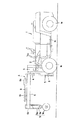
図1はボックスカルバート敷設装置の基本構造を示す側面図、図2ないし図6は上記ボックスカルバート敷設装置を使用してボックスカルバートを敷設する方法を示す説明図である。
【0028】
上記ボックスカルバート敷設装置は、エンジンなどの動力を搭載し、かつ車輪1aにより自走自在な作業車1と、この作業車1の前部に着脱自在に装着された作業機A及び押圧板Bよりなる。
上記作業機Aは車体1bの前側下部に枢着され、かつチルトシリンダ2により枢着部を中心に上部が前後方向へチルト自在な支持部材3を有しており、この支持部材3の両側には、車幅方向に離隔して左右一対の昇降杆4が設けられている。
【0029】
上記昇降杆4は下端側が支持部材4に昇降自在に支承されていると共に、内部には油圧シリンダよりなるリフタ5が収容されていて、このリフタ5により左右の昇降杆4が同時に昇降できるようになっている。
そして上記各昇降杆4の上端側には、水平に設けられた左右一対の支持フレーム6の後端が固着されている。
上記各支持フレーム6の中間部には、ボックスカルバート7を載置する載置台8が設置されていて、この載置台8の上面には、ボックスカルバート7の上部内面に下方より当接する複数のパッド8aが設けられている。
【0030】
また上記支持フレーム6の前端側は、横杆6aにより互いに連結されて、ボックスカルバート7を載置した際にも十分な強度が得られるよう枠組構造となっていると共に、各支持フレーム6の前端にはアウトリガ9の上端が固着されている。
上記アウトリガ9は上下方向に例えば2段に伸縮する伸縮杆9aと、この伸縮杆9a内に収容された油圧シリンダよりなる伸縮用シリンダ9b及び伸縮杆9aの下端に旋回自在に設けられたキャスタよりなる車輪9cより構成されていて、上記伸縮杆9aの上端が支持フレーム6の前端に固着されている。
【0031】
次に上記構成されたボックスカルバート敷設装置を使用してボックスカルバート7を敷設する方法を図2ないし図6に示す図面を参照して説明する。
ボックスカルバート7を地中へ敷設するに当って、まず地上より敷設計画線に沿って溝を開削し、溝の底部にコンクリートを打設して、ボックスカルバート7を設置するための路床12を構築する。
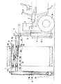
次に予め多数のボックスカルバート7を集積した集積場所へ作業車1を移動して、図2に示すようにボックスカルバート7の開口部側に作業車1を対峙させ、アウトリガ9の伸縮杆9aを収縮させた状態で、アウトリガ9側よりボックスカルバート7内へ作業機Aを進入させる。
このとき載置台8がボックスカルバート7の内側上面と干渉しないように、リフタ5により昇降杆4を下げておく。
【0032】
次に図3に示すように作業機Aの載置台8がボクッスカルバート7内のほぼ中央に達したら、リフタ5により昇降杆4を上昇させながら、伸縮シリンダ9bによりアウトリガ9の伸縮杆9aを伸長させる。
そして載置台8の上面がボックスカルバート7の内側上面に当接し、また伸縮杆9a下端の車輪9cが路面に接地したら、さらに昇降杆4を上昇させながら、伸縮杆9aを同量伸長させて、載置台8上に載置したボックスカルバート7を図4に示すように路面上より持ち上げる。
【0033】
次にこの状態で作業車1を自走させて、すでに設置されている既設のボックスカルバート7の接続端まで移動し、接続端の手前で作業車1を図5に示すように停止させる。
そしてこの状態でリフタ5により昇降杆4を下降させながら伸縮杆9aを収縮して、一旦ボックスカルバート7を路床12上に仮置きしたら、作業車1を少し前進させて、アウトリガ9を既設のボックスカルバート7内に図6に示すように進入し、この状態で再び伸縮杆9aを伸長させて、伸縮杆9a下端の車輪9cを既設ボックスカルバート7の内底面に接地させる。
【0034】
次にこの状態で昇降杆4を少し上昇させながら伸縮杆9aも少し伸長させて、ボックスカルバート7の底面を路床12より僅かに離間させたら、作業車1を前進させて、既設のボックスカルバート7の接続端に新たなボックスカルバート7を接続する。
また接続部に隙間が生じないよう、最後に作業車1を前進させて、押圧板Bでボクスカルバート7を押圧して完全に接続したら、両ボックスカルバート7間をボルトなどの固着具(図示せず)で締結する。
【0035】
以上のようにしてボックスカルバート7の接続が完了したら、作業車1を後退させて作業機Aをボックスカルバート7内より抜き出した後、次のボックスカルバート7を接続するために作業車1をボックスカルバート7の集積場所まで移動して、以下上記動作を繰返すもので、重量物であるボックスカルバート7を労力を必要とせずに敷設することができるようになる。
【0036】
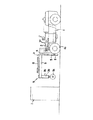
なお上記実施の形態では、図6に示すボックスカルバート7の接続工程において、リフタ5により昇降杆4を上昇させながらアウトリガ9の伸縮杆9aを伸長して、仮置きされたボックスカルバート7の底面を路床12より僅かに上昇させ、この状態で作業車1を前進させる作業を行うようにしたが、予め支持フレームに図7に示すような高さ調整手段14を設置することにより、この高さ調整手段14を使用してボックスカルバート7を持ち上げることができるため、リフタ5により昇降杆4を上昇させながら、同時にアウトリガ9の伸縮杆9aを伸長する操作が不要になり、接続作業はさらに容易となる。
【0037】
次にその実施の形態を図7を参照して説明する。
なお上記実施の形態と同一部分は同一符号を付してその説明は省略する。
作業車1の前部に装着された作業機Aの支持フレーム6の側面には、前後方向にガイドレール6aが敷設されていて、このガイドレール6aに前後調整手段15のキャリヤ15aがローラ15bを介して移動自在に支承されている。
上記キャリヤ15aと昇降杆4の間には、油圧シリンダよりなる前後移動シリンダ15cが横架されていて、この前後移動シリンダ15cによりキャリヤ15aが前後移動自在となっている。
【0038】
また上記キャリヤ15aには、高さ調整手段14のリンク14aと昇降シリンダ14bの一端側が枢着されている。
上記リンク14aはX字形に交差し、かつ交差部がピン14cにより枢着されたパンダグラフ状をなしていて、一方のリンク14aの一端が上記キャリヤ15aに枢着されており、他方のリンク14aの一端は昇降フレーム14dの一端側に枢着されている。
両リンク14aの他端側には、ローラ14eがそれぞれ回転自在に支承されていて、一方のローラ14eは上記ガイドレール6a内に、そして他方は昇降フレーム14dに敷設されたガイドレール14f内に転動自在に嵌合されていると共に、一方のリンク14aとキャリヤ15aの間に上記昇降シリンダ14bが横架されていて、この昇降シリンダ14bにより昇降フレーム14dが昇降自在となっている。
そしてこの昇降フレーム14d上に、ボックスカルバート7を載置する載置台8が設置されている。
【0039】
次に上記構成されたボックスカルバート敷設装置の作用を説明する。
なおボックスカルバート7を既設のボックスカルバート接続端まで移動する工程は上記実施の形態と同様なので、その説明は省略する。
【0040】
図8に示すように既設ボックスカルバート7の接続端までボックスカルバート7を移送したら、アウトリガ9の伸縮杆9aを収縮した後作業車1を前進させて、アウトリガ9を既設ボックスカルバート7内へ進入させ、この状態で再び伸縮杆9b伸長して車輪9cを既設ボックスカルバート7の内底面に接地させる。
次にこの状態で高調整手段14の昇降シリンダ14bを伸長して載置台8を上昇させ、仮置きされたボックスカルバート7を持ち上げたら、前後調整手段15の前後移動シリンダ15bを伸長してキャリヤ15aを前方へ移動し、既設のボックスカルバート7を接続して固着具で締結する。
【0041】
このとき、既設のボックスカルバート7に対し、新たに接続するボックスカルバート7の位置を正確に調整する場合は、高さ調整手段14によりボックスカルバート7の高さを微調整しながら、前後移動調整手段15により前後動を調整すればよく、微調整を可能にすることにより、短時間で精度よくボックスカルバート7の敷設が行えるようになる。
【0042】
以上は作業機Aの載置台8に高さ調整手段14及び前後調整手段15を付加した実施の形態であるが、さらに左右調整手段16及び旋回調整手段17を付加すれば、さらに正確な微調整が容易に行えると共に、曲線に沿った敷設も可能になる。
【0043】
この実施の形態で使用する作業車1は、図9に示すようにフォークリフトトラックで、車体1aの前部に、下部が車体1bに枢着されたマスト22が立設されており、このマスト22はチルトシリンダ23により上端側が前後方向へチルト自在となっている。
【0044】
上記マスト22の前側にはリフトシリンダ24により上下動自在なフィンガボード25が装着されていて、このフィンガボート25の前面側下部にピン25bにより作業機Aの支持部材3が枢着されている。
上記支持部材3の下部側には、フィンガボード25側へ係止杆26がほぼ水平に突設されている。
上記係止杆26の先端側下面には、図9の拡大図で示すように凹部26aが形成されていて、この凹部26a内にフィンガボード25の上部に突出された係止凸部25aが下方より嵌入されている。
【0045】
上記凹部26aの幅は、凸部25aより十分大きく形成されていて、マスト22がほぼ垂直のときには、凹部26a内で凸部25aが遊嵌状態にあり、マスト22を後方へ例えば5°チルトさせると、凸部25aが凹部26aと係合して、リフトシリンダ24により作業機A全体をリフトできるようになっている。
【0046】
上記作業機Aは、支持部材3の下部より前方へ支持フレーム6がほぼ水平に突設されており、支持フレーム6の前端にアウトリガ9の車輪9cが旋回自在に設けられている。
上記車輪9cはねじ軸27aと調整ナット27b及びロックナット27cよりなる高さ調整機構27により、敷設するボックスカルバート7のサイズに応じて高さが調整できるようになっていると共に、上記支持フレーム6の上側に高さ調整手段14が設けられている。
【0047】
上記高さ調整手段14は支持フレーム3と平行に設けられた昇降フレーム14dを有している。
上記昇降フレーム14dの一端側は、支持フレーム3に上下摺動自在に支承されている。
上記支持部材3内には油圧シリンダよりなるリフタ5が収容されていて、これらリフタ5より上方に突出されたピストン杆5aの先端にスプロケット5bが回転自在に支承されている。このスプロケット5bには、一端側が上記昇降フレーム14dに、そして他端側が支持部材3に結着されたチェーン14gが迂回されていて、リフタ5によりスプロケット5bを上下動させることにより、上記昇降フレーム14dが昇降できるようになっている。
【0048】
上記支持フレーム6と昇降フレーム14dの間には、支持フレーム6と平行した状態で昇降フレーム14dを上下動させるためのリンク14aが設けられている。
上記リンク14aは一対のリンクのほぼ中間部をピン14cで枢着したほぼX字形に形成されていて、各リンク14aの一端側は支持フレーム6と、昇降フレーム14dの前端側に枢着されている。各リンク14aの他端側には、ローラ14eが回転自在に支承されていて、これらローラ14eは支持フレーム6及び昇降フレーム14dの長手方向に布設されたガイドレール6a,14f内に回転動自在に嵌合されている。
【0049】
そして上記昇降フレーム14d上に、前後調整手段15のキャリヤ15aがローラ15bを介して前後動自在に載置されている。
上記キャリヤ15aと昇降フレーム14dの一端側に突設されたブラケット15eの間に、油圧シリンダよりなる前後移動シリンダ15cが横架されていて、この前後移動シリンダ15cによりキャリヤ15aが前後移動自在となっている。
【0050】
また上記キャリヤ15a内に左右調整手段18が、そして左右調整手段18上に旋回調整手段19が設置されている。
上記左右調整手段18は、左右の昇降フレーム14d上にこれらと直交するように横架された一対のガイドレール18aと、これらガイドレール18aの間に設けられた油圧シリンダよりなる一対の左右移動シリンダ18b及び左右移動体18cよりなる。
上記左右移動体18cは板体より形成されていて、下面に回転自在に支承された複数のローラ18dを有しており、これらローラ18dはチャンネル状に形成された上記ガイドレール18a内に転動自在に嵌合されている。
【0051】
また左右移動シリンダ18bの一端は、上記キャリヤ15aに枢着され、他端は上記左右移動体18cの下面に枢着されていて、この左右移動シリンダ18bにより、ガイドレール18aに沿って左右移動体18cが左右方向へ移動調整できるようになっている。
【0052】
一方旋回調整手段19は、ボックスカルバート7を載置する載置台8の下面中央を旋回自在に支持する支軸19aと、この支軸19aを中心に載置台8を旋回させる油圧シリンダよりなる一対の旋回シリンダ19bより構成されている。
【0053】
次に上記構成されたボックスカルバート敷設装置の作用を説明する。
なおボックスカルバート7を既設のボックスカルバート接続端まで移動する工程は上記何れの実施の形態とほぼ同様なので、その説明は省略する。
【0054】
図11に示すように既設ボックスカルバート7の接続端までボックスカルバート7を移送したら、リフタ5により昇降フレーム14dを下降させて一旦ボックスカルバート7を路床12上に仮置きした後、チルトシリンダ23によりマスト22を約5°後傾させて係止杆26の凹部26aをフォンガボード25の凸部25aに係合させる。
【0055】
次にこの状態でリフトシリンダ24によりフィンガボード25を上昇させて、作業機A全体をリフトさせる。
支持フレーム6先端の車輪9cの接地面が既設ボックスカルバート7の内底面より高くなったら、その位置で作業機Aのリフトを停止し、次に作業車1を前進させて支持フレーム6先端の車輪9cを既設ボックスカルバート7内へ進入させ、この状態で車輪9cが既設ボックスカルバート7の内底面に接地するまで作業機Aを下降させる。
【0056】
次にこの状態でリフタ5により昇降フレーム14fとともに載置台8を上昇させて、仮置きされたボックスカルバート7を図11に示すように持ち上げたら、既設のボックスカルバート7と新たに接続するボックスカルバート7の位置を調整するため、左右調整手段18の左右移動シリンダ18bにより左右移動体18cを移動して、新たに接続するボックスカルバート7の位置を調整する。
【0057】
また図12に示すようにボックスカルバート7を曲線に沿って敷設する場合は、旋回調整手段19の旋回シリンダ19bにより載置台8を旋回させて、既設ボックスカルバート7と新たに接続するボックスカルバート7の位置を微調整する。
【0058】
以上のようにして位置の微調整が完了したら、前後調整手段15の前後移動シリンダ15cによりキャリヤ15aを前進させながら、高さ調整手段14の昇降シリンダ14bを収縮して、ボックスカルバート7を路床12に接地させることにより、既設ボックスカルバート7に新たなボックスカルバート7を接続して固着具で締結するもので、高さ調整手段14、前後調整手段15、左右調整手段18及び旋回調整手段19によりボックスカルバート7の位置が3次元的に微調整できるため、既設のボックスカルバート7と、新たに接続するボックスカルバート7の位置決めが短時間で、かつ正確に行えるようになる。
特に図12に示すように曲線に沿ってボックスカルバート7を敷設する場合は、旋回調整手段19により旋回方向の微調整が可能となることにより、曲線施行も容易に行える。
【0059】
【発明の効果】
この発明は以上詳述したように、重量物であるボックスカルバートを作業機の載置台に載置して敷設現場まで迅速かつ安全に移送することができると共に、支持フレームの先端に設けられた車輪を既設ボクスカルバートの内底面に接地させて、ボックスカルバートの重量を支持しながら、ボックスカルバートを既設ボックスカルバートの接続部まで移動することができるため、作業時死角が生じることがない。
【0060】
これによってボックスカルバートの接続作業が安全かつ能率よく行えるようになる。また作業時土留鋼杭間に横架された切梁や胴梁などを気にせずに作業ができるようになると共に、レッカー車などでボックスカルバートを搬入する必要がないため、ボックスカルバートの吊上げが困難な場所での施工が可能になる上、レッカー車の移動が他の交通の妨げとなることがない。
【0061】
また前後調整手段や高さ調整手段、左右調整手段などを設けることによって既設ボックスカルバートに対して、新たに接続するボックスカルバートの位置決めや微調整が容易に行えるため、精度の高い敷設作業が可能になる。
さらに旋回調整手段を付加することにより、曲線施工も容易に行える。
【図面の簡単な説明】
【図1】 この発明の実施の形態において使用するボックスカルバート敷設装置の側面図である。
【図2】 この発明の実施の形態になるボックスカルバート敷設装置を使用してボックスカルバートを敷設する方法を示す工程図である。
【図3】 この発明の実施の形態になるボックスカルバート敷設装置を使用してボックスカルバートを敷設する方法を示す工程図である。
【図4】 この発明の実施の形態になるボックスカルバート敷設装置を使用してボックスカルバートを敷設する方法を示す工程図である。
【図5】 この発明の実施の形態になるボックスカルバート敷設装置を使用してボックスカルバートを敷設する方法を示す工程図である。
【図6】 この発明の実施の形態になるボックスカルバート敷設装置を使用してボックスカルバートを敷設する方法を示す工程図である。
【図7】 この発明の実施の形態において使用する別のボックスカルバート敷設装置の側面図である。
【図8】 この発明の実施の形態において使用する別のボックスカルバート敷設装置によりボックスカルバートを敷設している状態の作用説明図である。
【図9】 この発明の実施の形態において使用する別のボックスカルバート敷設装置の側面図である。
【図10】 この発明の実施の形態において使用する別のボックスカルバート敷設装置の平面図である。
【図11】 この発明の実施の形態において使用する別のボックスカルバート敷設装置によりボックスカルバートを敷設している状態の作用説明図である。
【図12】 ボックスカルバートの曲線施工例を示す説明図である。
【符号の説明】
1…作業車、4…昇降杆、5…リフタ、6…支持フレーム、8…載置台、9…アウトリガ、9a…伸縮杆、9b…伸縮シリンダ、9c…車輪、14…高さ調整手段、15…前後調整手段、18…左右調整手段、19…旋回調整手段、A…作業機、B…押圧板。[0001]
BACKGROUND OF THE INVENTION
This invention is a box culvert used for subway construction etc. Laying method About.
[0002]
[Prior art]
Conventionally, as a method of constructing a subway construction or a road, a culvert in the ground, a method of laying a box culvert in an excavated groove and backfilling the groove to bury the box culvert in the ground is generally known. .
[0003]
Also, this box culvert requires a lot of labor for laying because it is a heavy object pre-formed in a rectangular tube shape with concrete, but various laying methods have been proposed in the past to reduce this labor. Has been put to practical use.
[0004]
For example, Japanese Utility Model Publication No. 1-1825 includes a traveling carriage that travels on both sides of a concrete road bed on which a box culvert is placed, and a lifting platform that is disposed above the traveling carriage and that moves up and down by driving a cylinder. A box characterized in that the upper surface level of the pedestal is a lifting stroke extending above and below the concrete road bed surface, and further, a lateral feed device that is movable in a direction perpendicular to the traveling direction of the traveling carriage is arranged on the lifting platform. A culvert transport device has been proposed.
[0005]
[Problems to be solved by the invention]
In the transport device of the above publication, a box culvert, which is a heavy object, is placed and moved to the installation position, and the lateral movement is adjusted by the lateral feed device, and the position is aligned with the already laid bock culvert. The box culvert can be laid without requiring labor since it is connected later.
[0006]
However, in the transport device disclosed in the above publication, the box culvert previously placed on the concrete roadbed is scooped up from below and placed on the traveling carriage. Therefore, the box culvert is previously placed on the concrete roadbed using a tow truck or the like. It is necessary to keep it.
[0007]
For this reason, it is difficult to perform construction in a place where the box culvert cannot be lifted by a tow truck. There are also problems such as not being easy to carry in.
[0008]
The present invention has been made to remedy such conventional problems, and an object of the present invention is to provide a box culvert laying method and a laying apparatus that can quickly and safely transfer and lay a box culvert.
[0009]
[Means for Solving the Problems]
In order to achieve the above object, according to the first aspect of the present invention, when the upper part of the box culvert is placed on the work table mounted on the work vehicle from the inner surface side and conveyed to the laying site, it is already installed. Temporarily placed near the connection part of the box culvert, and then the work vehicle is advanced, and after the outrigger provided at the front part of the work implement enters the existing box culvert, the wheel provided at the lower part of the outrigger Is lowered and grounded to the inner bottom surface of the existing box culvert, and in this state, the work table is raised, the box culvert is again placed on the work table, and then the box culvert is moved forward. A new box culvert is connected to the connection portion of the.
[0010]
By the above method, the heavy box culvert can be quickly and safely transferred to the laying site, and the newly connected box culvert can be connected to the existing box culvert while the wheels under the outrigger roll on the inner bottom surface of the existing box culvert. Since it can move to a connection part, the connection work of the box culvert newly connected with the existing box culvert can be performed easily.
[0011]
Also, even if cut beams or trunk beams are installed horizontally between retaining steel piles driven along the inner wall of the groove, they can be installed without worrying about them, so that installation work can be performed safely and efficiently. become.
[0012]
To achieve the above purpose Box culvert laying equipment Has a self-propelled work vehicle and a work machine detachably attached to the front part of the work vehicle. The work machine is provided with a lift that can be lifted and lowered by a lifter, and an upper part of the lift. One end side is fixed, the other end side is protruded forward, an upper trigger is fixed to the other end of the support frame, and an outrigger having a wheel at the lower end is provided on the support frame, and By supporting the upper part of the box culvert from the inner surface side, it is composed of a mounting table on which the box culvert is mounted.
[0013]
After inserting the work implement into the box culvert to be laid with the above configuration and grounding the wheel under the outrigger, the box culvert can be mounted on the mounting table by raising the mounting table. Can be mounted.
This eliminates the need to use a tow truck to carry the box culvert onto the roadbed, so it can be used in places where it is impossible to lift the tow truck, and movement by the tow truck hinders traffic. There is no fear.
[0014]
In addition, since the box culvert can be quickly and safely transferred to the laying site, the work efficiency can be greatly improved, and the box culvert can be laid without touching obstacles such as beams. There is no risk of damaging piles or support works.
[0015]
To achieve the above purpose Box culvert laying equipment Is an outrigger composed of a telescopic rod having wheels at the bottom and a telescopic cylinder that expands and contracts the telescopic rod in the vertical direction.
[0016]
With the above configuration, the work machine can be easily inserted into the box culvert or the wheel can be grounded to the inner bottom surface of the existing box culvert.
[0017]
To achieve the above purpose Box culvert laying equipment Is provided with a front-rear adjusting means for moving the mounting table in the front-rear direction between the support frame and the mounting table.
[0018]
With the above configuration, when the box culvert is temporarily placed in the vicinity of the connection portion of the existing box culvert, the box culvert can be moved forward without moving the work vehicle forward, so that the connection work is facilitated.
[0019]
To achieve the above purpose Box culvert laying equipment Is provided with height adjusting means for raising and lowering the mounting table between the support frame and the mounting table.
[0020]
With the above configuration, the box culvert placed on the installation table can be moved in the left-right direction without moving the work vehicle.
[0021]
To achieve the above purpose Box culvert laying equipment Are provided with a front-rear adjusting means and a height adjusting means between the support frame and the mounting table.
[0022]
With the above configuration, the front and rear and the height direction of the box culvert placed on the installation table can be easily adjusted.
[0023]
To achieve the above purpose Box culvert laying equipment Are provided with a front-rear adjusting means, a height adjusting means, and a left-right adjusting means for moving the mounting table left and right between the support frame and the mounting table.
[0024]
With the above configuration, the front and rear, the left and right, and the height direction of the box culvert mounted on the mounting table can be easily adjusted.
[0025]
To achieve the above purpose Box culvert laying equipment Is provided with a front-rear adjusting means, a height adjusting means, a left-right adjusting means for moving the mounting table to the left and right, and a turning adjusting means for turning the mounting table between the support frame and the mounting table.
[0026]
With the above configuration, it is possible to adjust the turning direction in addition to the front / rear, left / right and height adjustments of the box culvert mounted on the mounting table. You will be able to do it accurately.
[0027]
DETAILED DESCRIPTION OF THE INVENTION
Embodiments of the present invention will be described in detail with reference to the drawings.
FIG. 1 is a side view showing a basic structure of a box culvert laying device, and FIGS. 2 to 6 are explanatory views showing a method of laying a box culvert using the box culvert laying device.
[0028]
The box culvert laying device includes a work vehicle 1 that is powered by an engine or the like and that can freely run by wheels 1a, and a work machine A and a pressing plate B that are detachably attached to the front portion of the work vehicle 1. Become.
The work machine A has a
[0029]
The elevating rod 4 is supported at its lower end by the support member 4 so as to be movable up and down, and a
And the rear end of a pair of left and right support frames 6 provided horizontally is fixed to the upper end side of each lifting / lowering rod 4.
A mounting table 8 on which the
[0030]
Further, the front end side of the
The
[0031]
Next, a method for laying the
In laying the
Next, the work vehicle 1 is moved to an accumulation place where a large number of
At this time, the lifting rod 4 is lowered by the
[0032]
Next, as shown in FIG. 3, when the mounting table 8 of the work machine A reaches almost the center in the
Then, when the upper surface of the mounting table 8 is in contact with the inner upper surface of the
[0033]
Next, in this state, the work vehicle 1 is self-propelled to move to the connection end of the existing
In this state, the lifting rod 4 is lowered by the
[0034]
Next, in this state, the elevating rod 4 is slightly lifted and the telescopic rod 9a is slightly extended so that the bottom surface of the
Further, when the work vehicle 1 is finally moved forward and the
[0035]
When the connection of the
[0036]
In the above embodiment, in the step of connecting the
[0037]
Next, the embodiment will be described with reference to FIG.
In addition, the same part as the said embodiment attaches | subjects the same code | symbol, and abbreviate | omits the description.
A guide rail 6a is laid in the front-rear direction on the side surface of the
Between the carrier 15a and the lifting / lowering rod 4, a front /
[0038]
The carrier 15a is pivotally connected to one end of the link 14a of the height adjusting means 14 and the elevating
The link 14a intersects in an X shape and forms a panda graph in which the intersecting portion is pivotally attached by a pin 14c. One end of one link 14a is pivotally attached to the carrier 15a, and the other link 14a Is pivotally attached to one end of the lifting frame 14d.
A mounting table 8 on which the
[0039]
Next, the operation of the box culvert laying apparatus constructed as described above will be described.
The process of moving the
[0040]
When the
Next, in this state, the elevating
[0041]
At this time, when the position of the newly connected
[0042]
The above is an embodiment in which the height adjusting means 14 and the front / rear adjusting means 15 are added to the mounting table 8 of the work machine A. However, if the left / right adjusting means 16 and the turning adjusting means 17 are further added, more accurate fine adjustment is possible. Can be easily performed, and laying along a curve is also possible.
[0043]
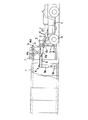
The working vehicle 1 used in this embodiment is a forklift truck as shown in FIG. 9, and a
[0044]
A
On the lower side of the
As shown in the enlarged view of FIG. 9, a concave portion 26a is formed on the lower surface of the distal end side of the locking
[0045]
The width of the concave portion 26a is sufficiently larger than the convex portion 25a. When the
[0046]
In the working machine A, a
The height of the
[0047]
The height adjusting means 14 has an elevating frame 14 d provided in parallel with the
One end side of the elevating frame 14d is supported by the
A
[0048]
Between the
The link 14a is formed in an approximately X shape in which a substantially middle portion of a pair of links is pivotally attached by a pin 14c. One end of each link 14a is pivotally attached to the
[0049]
On the elevating frame 14d, the carrier 15a of the front / rear adjusting means 15 is placed so as to be movable back and forth via a
Between the carrier 15a and a
[0050]
A left / right adjusting means 18 is installed in the carrier 15a, and a turning adjusting means 19 is installed on the left / right adjusting means 18.
The left / right adjusting means 18 includes a pair of left and right moving cylinders including a pair of guide rails 18a horizontally mounted on the left and right lifting frames 14d and a hydraulic cylinder provided between the guide rails 18a. 18b and left and right moving
The left-
[0051]
One end of the left /
[0052]
On the other hand, the turning adjusting means 19 includes a pair of support shafts 19a that rotatably support the center of the lower surface of the mounting table 8 on which the
[0053]
Next, the operation of the box culvert laying apparatus constructed as described above will be described.
Since the process of moving the
[0054]
When the
[0055]
Next, in this state, the
When the ground contact surface of the
[0056]
Next, when the mounting table 8 is lifted together with the
[0057]
When the
[0058]
When the fine adjustment of the position is completed as described above, the elevating
In particular, as shown in FIG. 12, when the
[0059]
【The invention's effect】
As described in detail above, the present invention enables a box culvert, which is a heavy object, to be quickly and safely transferred to a laying site by being placed on a work table, and a wheel provided at the tip of the support frame. Since the box culvert can be moved to the connecting portion of the existing box culvert while supporting the weight of the box culvert by grounding to the inner bottom surface of the existing box culvert, there is no blind spot during operation.
[0060]
As a result, the box culvert can be connected safely and efficiently. In addition, it is possible to work without worrying about the beams and trunk beams horizontally placed between the steel piles during work, and it is not necessary to carry the box culvert with a tow truck, so it is difficult to lift the box culvert. In addition, the construction of a towed vehicle is possible and the movement of the tow truck does not hinder other traffic.
[0061]
In addition, by installing front / rear adjustment means, height adjustment means, left / right adjustment means, etc., it is easy to position and fine-tune the newly connected box culvert with respect to the existing box culvert, enabling highly accurate laying work. Become.
Furthermore, curve construction can be easily performed by adding a turning adjustment means.
[Brief description of the drawings]
FIG. 1 shows an embodiment of the present invention. Use It is a side view of a box culvert laying device.
FIG. 2 is a process diagram showing a method of laying a box culvert using the box culvert laying apparatus according to the embodiment of the present invention.
FIG. 3 is a process diagram showing a method of laying a box culvert using the box culvert laying apparatus according to the embodiment of the present invention.
FIG. 4 is a process diagram showing a method of laying a box culvert using the box culvert laying apparatus according to the embodiment of the present invention.
FIG. 5 is a process diagram showing a method of laying a box culvert using the box culvert laying apparatus according to the embodiment of the present invention.
FIG. 6 is a process diagram showing a method of laying a box culvert using the box culvert laying apparatus according to the embodiment of the present invention.
FIG. 7 shows an embodiment of the present invention. Use another It is a side view of a box culvert laying device.
FIG. 8 shows an embodiment of the present invention. Use another It is operation | movement explanatory drawing of the state which is laying the box culvert by the box culvert laying apparatus.
FIG. 9 shows an embodiment of the present invention. Use another It is a side view of a box culvert laying device.
FIG. 10 shows an embodiment of the present invention. Use another It is a top view of a box culvert laying device.
FIG. 11 shows an embodiment of the present invention. Use another It is operation | movement explanatory drawing of the state which is laying the box culvert by the box culvert laying apparatus.
FIG. 12 is an explanatory view showing a curve construction example of a box culvert.
[Explanation of symbols]
DESCRIPTION OF SYMBOLS 1 ... Work vehicle, 4 ... Lifting rod, 5 ... Lifter, 6 ... Support frame, 8 ... Mounting stand, 9 ... Outrigger, 9a ... Telescopic rod, 9b ... Telescopic cylinder, 9c ... Wheel, 14 ... Height adjusting means, 15 ... front-rear adjusting means, 18 ... left-right adjusting means, 19 ... turning adjusting means, A ... working machine, B ... pressing plate.
Claims (1)
Priority Applications (1)
| Application Number | Priority Date | Filing Date | Title |
|---|---|---|---|
| JP05768197A JP3915044B2 (en) | 1997-03-12 | 1997-03-12 | Box culvert laying method |
Applications Claiming Priority (1)
| Application Number | Priority Date | Filing Date | Title |
|---|---|---|---|
| JP05768197A JP3915044B2 (en) | 1997-03-12 | 1997-03-12 | Box culvert laying method |
Publications (2)
| Publication Number | Publication Date |
|---|---|
| JPH10252128A JPH10252128A (en) | 1998-09-22 |
| JP3915044B2 true JP3915044B2 (en) | 2007-05-16 |
Family
ID=13062684
Family Applications (1)
| Application Number | Title | Priority Date | Filing Date |
|---|---|---|---|
| JP05768197A Expired - Fee Related JP3915044B2 (en) | 1997-03-12 | 1997-03-12 | Box culvert laying method |
Country Status (1)
| Country | Link |
|---|---|
| JP (1) | JP3915044B2 (en) |
Families Citing this family (5)
| Publication number | Priority date | Publication date | Assignee | Title |
|---|---|---|---|---|
| JP2002115499A (en) * | 2000-10-10 | 2002-04-19 | Kubota Corp | Pipe-conveying truck |
| JP2003239366A (en) * | 2002-02-13 | 2003-08-27 | Haneda Concrete Industrial Co Ltd | Concrete block transporter |
| JP2005132331A (en) * | 2003-10-10 | 2005-05-26 | Kaieitechno Co Ltd | Concrete block transport vehicle, and method for constructing concrete structure |
| JP6865151B2 (en) * | 2017-12-06 | 2021-04-28 | 前田製管株式会社 | Heavy load carrier |
| JP7050134B2 (en) * | 2020-09-14 | 2022-04-07 | 前田製管株式会社 | How to handle heavy goods |
Family Cites Families (4)
| Publication number | Priority date | Publication date | Assignee | Title |
|---|---|---|---|---|
| JP2925125B2 (en) * | 1991-11-12 | 1999-07-28 | 鹿島道路株式会社 | Joint groove burying method and device |
| JP2898492B2 (en) * | 1992-12-21 | 1999-06-02 | 日本ヒューム管株式会社 | Undercarriage trolley and culvert installation method |
| JP3254610B2 (en) * | 1993-02-26 | 2002-02-12 | 清水建設株式会社 | Plumbing method and plumbing device used in the method |
| JPH06330551A (en) * | 1993-05-25 | 1994-11-29 | Ito Seizo | Transportation of box culvert and its device |
-
1997
- 1997-03-12 JP JP05768197A patent/JP3915044B2/en not_active Expired - Fee Related
Also Published As
| Publication number | Publication date |
|---|---|
| JPH10252128A (en) | 1998-09-22 |
Similar Documents
| Publication | Publication Date | Title |
|---|---|---|
| US4360293A (en) | Canal paving machine | |
| CN109236302B (en) | Variable section excavation trolley in tunnel | |
| CA2561430C (en) | Railway rail handling apparatus and method | |
| JP3188562B2 (en) | Roadbed tamping machine | |
| US4773332A (en) | Mobile apparatus for loading, transporting and laying an assembled track section | |
| JP3915044B2 (en) | Box culvert laying method | |
| CN112252099A (en) | Operating vehicle for railway turnout replacement and operating method thereof | |
| JP4763119B2 (en) | Crawler mounted crane | |
| US4874271A (en) | Self-propelled trench shoring machine | |
| JP3856564B2 (en) | Steel pipe pile driving device and steel pipe pile driving method | |
| CA1242993A (en) | Crane system | |
| JP2539151B2 (en) | Excavation method for bottom floor in tunnel | |
| JPH06185106A (en) | Installing cart and installing method for culvert | |
| CN211819422U (en) | Lifting walking template trolley suitable for construction of curve tunnel | |
| CN115448228A (en) | Lifting platform operation vehicle and operation method thereof | |
| JP2001206671A (en) | Portal carriage for burying pipe | |
| JP3254610B2 (en) | Plumbing method and plumbing device used in the method | |
| JP2814432B2 (en) | Concrete product installation method and installation device | |
| JP3876042B2 (en) | Auger screw detachable low skyhead pile driver | |
| JP2577577Y2 (en) | Truck for moving tubing equipment | |
| JPH06330551A (en) | Transportation of box culvert and its device | |
| CN220336909U (en) | Self-track-laying traveling device and tunnel lining trolley | |
| JP3980772B2 (en) | Removal and installation of heavy structures | |
| JP3395063B2 (en) | Installation machine for concrete products | |
| JPS592239Y2 (en) | Support beam for conveyor for small-section shield excavation |
Legal Events
| Date | Code | Title | Description |
|---|---|---|---|
| A521 | Written amendment |
Free format text: JAPANESE INTERMEDIATE CODE: A523 Effective date: 20040127 |
|
| A621 | Written request for application examination |
Free format text: JAPANESE INTERMEDIATE CODE: A621 Effective date: 20040127 |
|
| A977 | Report on retrieval |
Free format text: JAPANESE INTERMEDIATE CODE: A971007 Effective date: 20060118 |
|
| A131 | Notification of reasons for refusal |
Free format text: JAPANESE INTERMEDIATE CODE: A131 Effective date: 20060215 |
|
| A521 | Written amendment |
Free format text: JAPANESE INTERMEDIATE CODE: A523 Effective date: 20060406 |
|
| A02 | Decision of refusal |
Free format text: JAPANESE INTERMEDIATE CODE: A02 Effective date: 20060920 |
|
| A521 | Written amendment |
Free format text: JAPANESE INTERMEDIATE CODE: A523 Effective date: 20061019 |
|
| A911 | Transfer of reconsideration by examiner before appeal (zenchi) |
Free format text: JAPANESE INTERMEDIATE CODE: A911 Effective date: 20061222 |
|
| TRDD | Decision of grant or rejection written | ||
| A01 | Written decision to grant a patent or to grant a registration (utility model) |
Free format text: JAPANESE INTERMEDIATE CODE: A01 Effective date: 20070117 |
|
| A61 | First payment of annual fees (during grant procedure) |
Free format text: JAPANESE INTERMEDIATE CODE: A61 Effective date: 20070124 |
|
| R150 | Certificate of patent or registration of utility model |
Free format text: JAPANESE INTERMEDIATE CODE: R150 |
|
| FPAY | Renewal fee payment (event date is renewal date of database) |
Free format text: PAYMENT UNTIL: 20110216 Year of fee payment: 4 |
|
| FPAY | Renewal fee payment (event date is renewal date of database) |
Free format text: PAYMENT UNTIL: 20120216 Year of fee payment: 5 |
|
| FPAY | Renewal fee payment (event date is renewal date of database) |
Free format text: PAYMENT UNTIL: 20130216 Year of fee payment: 6 |
|
| FPAY | Renewal fee payment (event date is renewal date of database) |
Free format text: PAYMENT UNTIL: 20130216 Year of fee payment: 6 |
|
| R250 | Receipt of annual fees |
Free format text: JAPANESE INTERMEDIATE CODE: R250 |
|
| R250 | Receipt of annual fees |
Free format text: JAPANESE INTERMEDIATE CODE: R250 |
|
| R250 | Receipt of annual fees |
Free format text: JAPANESE INTERMEDIATE CODE: R250 |
|
| LAPS | Cancellation because of no payment of annual fees |