JP3914537B2 - Dual antenna coil transponder system - Google Patents
Dual antenna coil transponder system Download PDFInfo
- Publication number
- JP3914537B2 JP3914537B2 JP2003542507A JP2003542507A JP3914537B2 JP 3914537 B2 JP3914537 B2 JP 3914537B2 JP 2003542507 A JP2003542507 A JP 2003542507A JP 2003542507 A JP2003542507 A JP 2003542507A JP 3914537 B2 JP3914537 B2 JP 3914537B2
- Authority
- JP
- Japan
- Prior art keywords
- antenna
- circuit
- interrogator
- signal
- antenna coil
- Prior art date
- Legal status (The legal status is an assumption and is not a legal conclusion. Google has not performed a legal analysis and makes no representation as to the accuracy of the status listed.)
- Expired - Lifetime
Links
- 230000009977 dual effect Effects 0.000 title abstract description 5
- 230000005672 electromagnetic field Effects 0.000 claims description 8
- 230000001360 synchronised effect Effects 0.000 claims description 6
- 238000001514 detection method Methods 0.000 claims description 2
- 230000008878 coupling Effects 0.000 abstract description 9
- 238000010168 coupling process Methods 0.000 abstract description 9
- 238000005859 coupling reaction Methods 0.000 abstract description 9
- 239000000284 extract Substances 0.000 abstract description 4
- 239000003990 capacitor Substances 0.000 description 31
- 238000010586 diagram Methods 0.000 description 13
- 230000001939 inductive effect Effects 0.000 description 10
- 241001465754 Metazoa Species 0.000 description 9
- 238000004891 communication Methods 0.000 description 8
- 230000008859 change Effects 0.000 description 5
- 238000000034 method Methods 0.000 description 5
- 230000006870 function Effects 0.000 description 4
- 230000010363 phase shift Effects 0.000 description 4
- 239000000969 carrier Substances 0.000 description 3
- 238000012937 correction Methods 0.000 description 3
- 230000006698 induction Effects 0.000 description 3
- 238000012545 processing Methods 0.000 description 2
- 230000004044 response Effects 0.000 description 2
- 238000004804 winding Methods 0.000 description 2
- 230000003321 amplification Effects 0.000 description 1
- 238000013459 approach Methods 0.000 description 1
- 230000006399 behavior Effects 0.000 description 1
- 230000009286 beneficial effect Effects 0.000 description 1
- 230000005540 biological transmission Effects 0.000 description 1
- 238000006243 chemical reaction Methods 0.000 description 1
- 239000013078 crystal Substances 0.000 description 1
- 238000013480 data collection Methods 0.000 description 1
- 230000000694 effects Effects 0.000 description 1
- 230000005669 field effect Effects 0.000 description 1
- 210000001035 gastrointestinal tract Anatomy 0.000 description 1
- 230000036541 health Effects 0.000 description 1
- 239000007943 implant Substances 0.000 description 1
- 244000144972 livestock Species 0.000 description 1
- 230000007246 mechanism Effects 0.000 description 1
- 238000003199 nucleic acid amplification method Methods 0.000 description 1
- 230000009467 reduction Effects 0.000 description 1
- 238000012552 review Methods 0.000 description 1
- 239000004065 semiconductor Substances 0.000 description 1
- 230000035945 sensitivity Effects 0.000 description 1
- 210000002784 stomach Anatomy 0.000 description 1
- 230000001052 transient effect Effects 0.000 description 1
Images


Classifications
-
- H—ELECTRICITY
- H01—ELECTRIC ELEMENTS
- H01Q—ANTENNAS, i.e. RADIO AERIALS
- H01Q1/00—Details of, or arrangements associated with, antennas
- H01Q1/12—Supports; Mounting means
- H01Q1/22—Supports; Mounting means by structural association with other equipment or articles
- H01Q1/2208—Supports; Mounting means by structural association with other equipment or articles associated with components used in interrogation type services, i.e. in systems for information exchange between an interrogator/reader and a tag/transponder, e.g. in Radio Frequency Identification [RFID] systems
- H01Q1/2216—Supports; Mounting means by structural association with other equipment or articles associated with components used in interrogation type services, i.e. in systems for information exchange between an interrogator/reader and a tag/transponder, e.g. in Radio Frequency Identification [RFID] systems used in interrogator/reader equipment
-
- H—ELECTRICITY
- H04—ELECTRIC COMMUNICATION TECHNIQUE
- H04B—TRANSMISSION
- H04B1/00—Details of transmission systems, not covered by a single one of groups H04B3/00 - H04B13/00; Details of transmission systems not characterised by the medium used for transmission
- H04B1/59—Responders; Transponders
-
- G—PHYSICS
- G06—COMPUTING; CALCULATING OR COUNTING
- G06K—GRAPHICAL DATA READING; PRESENTATION OF DATA; RECORD CARRIERS; HANDLING RECORD CARRIERS
- G06K7/00—Methods or arrangements for sensing record carriers, e.g. for reading patterns
- G06K7/10—Methods or arrangements for sensing record carriers, e.g. for reading patterns by electromagnetic radiation, e.g. optical sensing; by corpuscular radiation
- G06K7/10009—Methods or arrangements for sensing record carriers, e.g. for reading patterns by electromagnetic radiation, e.g. optical sensing; by corpuscular radiation sensing by radiation using wavelengths larger than 0.1 mm, e.g. radio-waves or microwaves
- G06K7/10316—Methods or arrangements for sensing record carriers, e.g. for reading patterns by electromagnetic radiation, e.g. optical sensing; by corpuscular radiation sensing by radiation using wavelengths larger than 0.1 mm, e.g. radio-waves or microwaves using at least one antenna particularly designed for interrogating the wireless record carriers
- G06K7/10336—Methods or arrangements for sensing record carriers, e.g. for reading patterns by electromagnetic radiation, e.g. optical sensing; by corpuscular radiation sensing by radiation using wavelengths larger than 0.1 mm, e.g. radio-waves or microwaves using at least one antenna particularly designed for interrogating the wireless record carriers the antenna being of the near field type, inductive coil
-
- G—PHYSICS
- G08—SIGNALLING
- G08B—SIGNALLING OR CALLING SYSTEMS; ORDER TELEGRAPHS; ALARM SYSTEMS
- G08B13/00—Burglar, theft or intruder alarms
- G08B13/22—Electrical actuation
- G08B13/24—Electrical actuation by interference with electromagnetic field distribution
- G08B13/2402—Electronic Article Surveillance [EAS], i.e. systems using tags for detecting removal of a tagged item from a secure area, e.g. tags for detecting shoplifting
- G08B13/2465—Aspects related to the EAS system, e.g. system components other than tags
- G08B13/2468—Antenna in system and the related signal processing
- G08B13/2477—Antenna or antenna activator circuit
-
- H—ELECTRICITY
- H01—ELECTRIC ELEMENTS
- H01Q—ANTENNAS, i.e. RADIO AERIALS
- H01Q1/00—Details of, or arrangements associated with, antennas
- H01Q1/12—Supports; Mounting means
- H01Q1/22—Supports; Mounting means by structural association with other equipment or articles
- H01Q1/2208—Supports; Mounting means by structural association with other equipment or articles associated with components used in interrogation type services, i.e. in systems for information exchange between an interrogator/reader and a tag/transponder, e.g. in Radio Frequency Identification [RFID] systems
-
- H—ELECTRICITY
- H01—ELECTRIC ELEMENTS
- H01Q—ANTENNAS, i.e. RADIO AERIALS
- H01Q7/00—Loop antennas with a substantially uniform current distribution around the loop and having a directional radiation pattern in a plane perpendicular to the plane of the loop
Landscapes
- Engineering & Computer Science (AREA)
- Physics & Mathematics (AREA)
- Health & Medical Sciences (AREA)
- Toxicology (AREA)
- Electromagnetism (AREA)
- General Physics & Mathematics (AREA)
- Computer Networks & Wireless Communication (AREA)
- Signal Processing (AREA)
- Computer Vision & Pattern Recognition (AREA)
- Artificial Intelligence (AREA)
- Theoretical Computer Science (AREA)
- General Health & Medical Sciences (AREA)
- Automation & Control Theory (AREA)
- Computer Security & Cryptography (AREA)
- Near-Field Transmission Systems (AREA)
- Radar Systems Or Details Thereof (AREA)
- Variable-Direction Aerials And Aerial Arrays (AREA)
- Burglar Alarm Systems (AREA)
Abstract
Description
本発明は、無線タグ(RFID)システムに関する。特に本発明は、誘導的にトランスポンダに結合し、トランスポンダからデータを引き出す、改良されたデュアルアンテナコイルアンテナおよび信号処理RFIDインテロゲータあるいはリーダに関する。トランスポンダをエナジャイズするようにリーダによって発せられる磁界は、2つの原則的に同一である、距離をあけて配置されたアンテナコイルに電流を流すことによって生成される。 The present invention relates to a wireless tag (RFID) system. In particular, the present invention relates to an improved dual antenna coil antenna and signal processing RFID interrogator or reader that inductively couples to and extracts data from the transponder. The magnetic field emitted by the reader to energize the transponder is generated by passing a current through two spaced antenna coils that are identical in principle.
自動データ識別産業では、対象物および/あるいはデータをトランスポンダが取り付けられた対象とみなして追跡する方法として、インテロゲータ(リーダとしても知られている)とトランスポンダ(タグとしても知られている)とを含み得る協同識別システム(cooperative identification system)の使用は突出して増えてきている。トランスポンダは一般的に半導体メモリであり、そこにはデジタル情報が記憶されている。誘導結合として知られる技術を用いて、トランスポンダは、インテロゲータによって生成される電磁界に応答して、記憶されているデータをインテロゲータに与える。この種の誘導結合識別システムは非常に用途が広い。トランスポンダは、インテロゲータによって提供される電磁界から電力を引き出すというように受動的であってもよく、あるいは自身の電源を有するというように能動的であってもよい。受動トランスポンダは、「半二重」トランスポンダか「全二重」トランスポンダのどちらかであり、非常に小さく、軽くかつ安価なユニットとして製造することができる。インテロゲータ−トランスポンダシステムは、キロヘルツからギガヘルツまでの広い周波数で動作するようにされる。インテロゲータは、携帯可能で、小型バッテリによって電力を供給されてもよい。あるいは固定されており、バッテリあるいはAC電源から電力を供給されてもよい。 The automatic data identification industry uses interrogators (also known as readers) and transponders (also known as tags) as a way to track objects and / or data as if they were transponder-attached objects. The use of cooperating identification systems that can be included has increased significantly. The transponder is generally a semiconductor memory in which digital information is stored. Using a technique known as inductive coupling, the transponder provides stored data to the interrogator in response to the electromagnetic field generated by the interrogator. This type of inductive coupling identification system is very versatile. The transponder may be passive, such as drawing power from the electromagnetic field provided by the interrogator, or active, such as having its own power source. Passive transponders are either “half-duplex” transponders or “full-duplex” transponders and can be manufactured as very small, light and inexpensive units. Interrogator-transponder systems are made to operate over a wide frequency range from kilohertz to gigahertz. The interrogator is portable and may be powered by a small battery. Alternatively, it may be fixed and supplied with power from a battery or an AC power source.
これらの利点から、誘導結合識別システムは、移動する、あるいはアクセスできない対象とみなして情報を追跡することが望まれる多くのタイプのアプリケーションで用いられている。さまざまなアプリケーションには、資産および在庫管理、アクセス管理、自動車の料金徴収、駐車および保有車両管理のような交通に関するアプリケーションが含まれる。他のアプリケーションには、動物の健康、行動および場所のような情報を提供するようにトランスポンダを動物に取り付けることがある。トランスポンダを取り付ける一つの方法では、動物にトランスポンダを埋め込む。例えば、トランスポンダは、動物の皮膚の下に埋め込まれたり、あるいは飲み込まれたりした時に、動物の胃や消化管にとどまるように設計される。受動トランスポンダは、このタイプのアプリケーションに一意的に適応される。なぜなら、これらは、使い切ってしまう可能性のあるバッテリのような内部電源を必要としないからである。 Because of these advantages, inductively coupled identification systems are used in many types of applications where it is desired to track information as a moving or inaccessible object. Various applications include traffic related applications such as asset and inventory management, access management, car toll collection, parking and fleet management. Other applications include attaching transponders to animals to provide information such as animal health, behavior and location. One way of attaching the transponder is to implant the transponder in the animal. For example, transponders are designed to remain in the animal's stomach or digestive tract when implanted or swallowed under the animal's skin. Passive transponders are uniquely adapted to this type of application. This is because they do not require an internal power source such as a battery that can be used up.
誘導結合識別システムは、トランスポンダと誘導結合する電磁界を、アンテナコイルを通じて生成するインテロゲータを使用し得る。トランスポンダは、受動的であってもよく、アンテナとしても、発生された電磁界から電力を取り出してトランスポンダの電気回路に供給する誘導電源としても機能する誘導アンテナコイルに結合されるメモリ素子を有してもよい。インテロゲータにデータを提供する一つの方法では、トランスポンダが識別データをインテロゲータに再送信する。このアプローチは、インテロゲータ、トランスポンダの双方に送受信回路を必要とする。あるいは、トランスポンダを小型化することが望ましいので、トランスポンダにおいてできるだけ多くの部品をなくすことは有益である。したがって、インテロゲータにデータを提供する他の方法では、トランスポンダ内に可変の負荷が提供される。データを出コードするために、インテロゲータは、インテロゲータのパワー出力と、トランスポンダによる負荷とを測定する。変調されたパワー信号がデコードされて、後のデジタル解釈のたにのデータ要素を分離する。 The inductive coupling identification system may use an interrogator that generates an electromagnetic field inductively coupled with the transponder through the antenna coil. The transponder may be passive and has a memory element coupled to the induction antenna coil that functions as an antenna and also as an induction power source that extracts power from the generated electromagnetic field and supplies it to the electrical circuit of the transponder. May be. In one method of providing data to the interrogator, the transponder retransmits the identification data to the interrogator. This approach requires transmission and reception circuits for both the interrogator and the transponder. Alternatively, it is desirable to reduce the size of the transponder, so it is beneficial to eliminate as many parts as possible in the transponder. Thus, other methods of providing data to the interrogator provide a variable load within the transponder. To code out the data, the interrogator measures the power output of the interrogator and the load from the transponder. The modulated power signal is decoded to separate the data elements for later digital interpretation.
従来の誘導結合識別システムの欠点は、トランスポンダの誘導アンテナコイルとインテロゲータのフィールドアンテナコイルによって生成される電磁界の誘導結合は、インテロゲータのフィールドアンテナコイルとトランスポンダの誘導アンテナコイルとの間の距離に依存し得るということである。インテロゲータのフィールドアンテナコイルとトランスポンダの誘導アンテナコイルとの距離が最小であれば、誘導結合は最大となる。しかしこの距離が比較的遠ければ、誘導結合は無視できるほどになり、効果が弱くなる。したがって、トランスポンダを読み取る有効範囲を増やしたインテロゲータを提供することが望ましい。 The disadvantage of the conventional inductive coupling identification system is that the inductive coupling of the electromagnetic field generated by the transponder's inductive antenna coil and the interrogator's field antenna coil depends on the distance between the interrogator's field antenna coil and the transponder's inductive antenna coil It can be. Inductive coupling is maximized when the distance between the interrogator field antenna coil and the transponder induction antenna coil is minimal. However, if this distance is relatively long, the inductive coupling becomes negligible and the effect becomes weaker. Therefore, it is desirable to provide an interrogator with an increased effective range for reading transponders.
従来の誘導結合識別システムにおいては、インテロゲータは、トランスポンダタグ以外の導電性の物体によって引き起こされる磁界の乱れを取り込むことができないか、あるいはそのように設計されていなかった。例えば、アンテナコイルの近くを歩いている動物または人間は、インテロゲータが発生している磁界と磁気的に反応し得る。しかし従来のRFIDシステムは、磁界の乱れを検出する感度および/あるいは回路を欠いている。したがって、トランスポンダタグ以外の導電性の物体を検出することができるインテロゲータを提供することが望ましい。 In conventional inductive coupling identification systems, interrogators have been unable to capture or have not been designed for magnetic field disturbances caused by conductive objects other than transponder tags. For example, an animal or human walking near the antenna coil can react magnetically with the magnetic field generated by the interrogator. However, conventional RFID systems lack the sensitivity and / or circuitry to detect magnetic field disturbances. Therefore, it is desirable to provide an interrogator that can detect conductive objects other than transponder tags.
本発明は、2つのアンテナコイルを有するインテロゲータを提供する。それらは、それらの近くにトランスポンダタグが配置されたときに、トランスポンダタグが読み取られることができるように配置される。このインテロゲータは、トランスポンダタグ以外の導電性の物体を検出することも可能である。一実施形態において、各アンテナコイルは、同一の、かつ好ましくは逆位相の磁界を生成するように駆動される。回路内のトランスフォーマのような装置は、アンテナコイル間の電流の差を測定する。トランスポンダをエナジャイズする、および/あるいは導電性の物体を検出するのに必要とされる磁界は、例えばここで述べる構成を変えるアンテナコイル等のアンテナを流れる電流によって発生される。アンテナは、タグが読み取られ得る、あるいは物体が検出され得る領域の近くに配置される。好ましくは、アンテナコイルは同一であり、逆極性である。しかし、異なるアンテナおよび/あるいは逆極性ではないアンテナコイルを用いることは本発明の範囲内である。
トランスポンダが2つのアンテナの隣に配置され アクティブにされると、アンテナコイルの磁界内で変化が誘発される。この変化は、2つのアンテナコイル間で測定される時間とともに変化する差分電流を引き起こし、これがトランスポンダに記憶されているデータを反映する。差分電流は、読み取られ、フィルタに通され、デコードされる。本発明の一実施形態において、アンテナ−アンテナコイルドライバ信号を共鳴に合わせる自動調節回路が設けられている。トランスポンダタグあるいは導電性の物体のような対象以外の現象によって引き起こされるいかなる差分電流をも無効にする自動零調回路も設けられてもよい。
The present invention provides an interrogator having two antenna coils. They are positioned so that the transponder tags can be read when the transponder tags are positioned near them. This interrogator can also detect conductive objects other than transponder tags. In one embodiment, each antenna coil is driven to generate an identical and preferably anti-phase magnetic field. Devices such as transformers in the circuit measure the difference in current between the antenna coils. The magnetic field required to energize the transponder and / or detect conductive objects is generated by current flowing through an antenna, such as an antenna coil that changes configuration described herein. The antenna is placed near the area where the tag can be read or the object can be detected. Preferably, the antenna coils are the same and have opposite polarity. However, it is within the scope of the present invention to use different antennas and / or antenna coils that are not of opposite polarity.
When the transponder is placed next to the two antennas and activated, a change is induced in the magnetic field of the antenna coil. This change causes a differential current that varies with time measured between the two antenna coils, which reflects the data stored in the transponder. The differential current is read, passed through a filter and decoded. In one embodiment of the present invention, an automatic adjustment circuit is provided for matching the antenna-antenna coil driver signal to resonance. An automatic zeroing circuit may also be provided that disables any differential current caused by phenomena other than the subject, such as transponder tags or conductive objects.
発明の他のシステム、方法、特徴および効果は、この後の図面および詳細な説明を検討することで当業者には明らかになるであろう。そのようなさらなるシステム、方法、特徴および効果の全ては、この説明内に含まれ、発明の範囲内に含まれ、添付のクレームによって保護されるということに留意されたい。 Other systems, methods, features and advantages of the invention will become apparent to those skilled in the art upon review of the following drawings and detailed description. It should be noted that all such additional systems, methods, features and advantages are included within this description, are within the scope of the invention, and are protected by the appended claims.
図1は、本発明のRFIDインテロゲータの基本的な構成要素を示している。インテロゲータ全体100は、アナログの電気的構成要素、デジタルの電気的構成要素、あるいはこれらの組み合わせから構成されてもよい。したがって、インテロゲータ100の主要な電気的な構成要素は、単一のICチップ、PCボード、あるいは、当業者に知られているいかなる適切な回路基板および/あるいはアセンブリ上に構築されてもよい。また、このシステムは、2つのアンテナコイル112および114を有しており、これらは、アンテナコイル112および114によって発生される場の中にトランスポンダタグが配置されたときにトランスポンダタグが読み取り可能であるように、配置されている。アンテナコイル112、114を駆動するキャリア信号は、プロセッサ102によって発生され、アンテナコイル駆動信号を発生するようにアンテナコイルドライバ/電源回路104に供給される。アンテナコイルドライバ/電源回路104は、回路のインピーダンスをアンテナコイル112、114に整合されることが可能であるインピーダンス整合回路網を有する。さらに、アンテナコイルドライバ/電源回路104は、所望の共振に自動的に回路を調整可能である自動調整回路網(後述する)を有している。
FIG. 1 shows the basic components of the RFID interrogator of the present invention. The
スプリッタ106は、アンテナコイルドライバ/電源回路104からのアンテナコイル駆動信号を受け取って、アンテナコイル112、114に均等に電流を分割する。トランスポンダがアンテナコイル112、114の近傍において発生される場に配置され、アンテナコイル112、114からの信号によってアクティブにされると、アンテナコイル112、114によって生成される磁界において測定可能な変化が引き起こされる。この変化は、2つのアンテナコイル112、114で測定可能である差分電流を引き起こし、これが半二重トランスポンダか全二重トランスポンダのいずれかに含まれているデータを反映し、および/あるいはアンテナコイル112、114によって生成される磁界を通るあるいはそばの導電性の物体を示す。
The
本発明によると、動物や人間といった物体および/あるいは導電性の他の物体を検出することができる。例えば、牛のような動物がアンテナコイルの間、あるいはそばを通ると、牛の存在がアンテナコイル112、114によって発生されている場における反応を発生し、磁場の測定可能な乱れを生じさせる。この乱れは、2つのアンテナコイル112、114の差分電流を引き起こし、これをスプリッタ106に通信可能に結合されているリーダが検出することができる。この特徴は、動物、人間、および/あるいは、磁気反応を起こさせる他の物体を追跡するのに用いることができる。この特徴は、トランスポンダタグをもたない導電性の物体がアンテナコイルを通り抜けたことを示すのにも用いることができる。導電性の物体の検出を示す手段は、サイレン、ホーン、光、あるいは当業者に知られている他のどのような機構の出力であってもよい。
According to the present invention, objects such as animals and humans and / or other conductive objects can be detected. For example, when an animal, such as a cow, passes between or near the antenna coils, the presence of the cow causes a reaction in the field generated by the antenna coils 112, 114, causing a measurable disturbance in the magnetic field. This perturbation causes a differential current in the two
本実施形態は、スプリッタ106内にアンテナコイルバランス回路を有している。これは、動作に先立ち、あるいは動作中にアンテナコイル112、114の両方のインピーダンスを整合させることを可能にする。これは例えば、スプリッタ106内で調整可能な差動インダクタ、および/あるいは調整可能な抵抗を用いることによって実現される。
In the present embodiment, an antenna coil balance circuit is provided in the
RFIDインテロゲータ100は、スプリッタ106につながれた受信回路108を有している。受信回路108は、アンテナコイル112、114の磁界の近く、あるいは中にある半二重あるいは全二重トランスポンダおよび/あるいは導電性の物体によって発生される差分信号を受け取る。また、RFIDインテロゲータ100は、信号をデコードする、受信回路108につながれたデコーダ回路110も有している。また、アンテナコイル112、114を駆動する信号間のオフセットを連続的に(トランスポンダの読み取りの間で)ゼロにする自動零調回路を受信回路108に設けてもよい。
The
図2は、図1のインテロゲータ100のブロック図の一例である。多くの回路および構成要素の変更がかんば得られ、それらを用いることは本発明の範囲から逸脱しないということに留意されたい。したがって、インテロゲータ100’は、図1に示されたインテロゲータ100の例示的な一実施形態を表している。図1の構成要素102、104、106、108、110、112、114に対応する回路ブロックが図2にもっと詳しく示されている。インテロゲータ100は、AC線で電力を供給されるDC供給源あるいは蓄電池のいずれかから得られるDC電源202で動作する。DC電源はさらに、レギュレータ(図示せず)によってさまざまな電圧レベルに分割される。
FIG. 2 is an example of a block diagram of the
述べたように、プロセッサ102は、電気的消去可能ROM(EEPROM)204、制御プロセッサ206、キャリアジェネレータ208、ハウスキーピングプロセッサ210および通信入出力(COMM I/O)プロセッサ212を有する。これらの構成要素のそれぞれは、データおよび指令をプロセッサ102内で共有するように電気的に相互に接続されている。
As stated, the
アンテナコイルドライバ/電源回路104は、電源202に加えて、コイルドライバスイッチ214、電力レベル調整部216、インピーダンス整合回路網218、および自動調整部220を有している。これらの構成要素は、下記に述べるように、キャリアジェネレータ208からコイルドライブスイッチ214に入力を受け取り、コイル駆動信号をスプリッタ106に出力するように相互に接続されている。
The antenna coil driver /
スプリッタ106は、アンテナコイルドライバ/電源回路104からコイル駆動信号を受け取る信号スプリッタ222を有している。スプリッタ106は、図2に示すように、コイルバランス回路234を有していてもよく、これはスプリッタ222とアンテナコイル112、114との間に配置される。アンテナコイル112および114は、グラウンド237への共通の出力を有してもよい。
The
スプリッタ106は、アンテナコイル112および114を駆動するだけではなく、アンテナコイル112および114からの信号を受信回路108に出力する。受信回路108は自動零調部224を有しており、これがスプリッタ106からの信号を受け取って、自動零調処理の後に受信部アンプフィルタ226へ信号を送る。受信部アンプフィルタ226は同期復調部228に信号を出力する。これもプロセッサ102からのキャリアジェネレータ208からの入力信号を受け取る。同期復調部228は、出力信号を整流部230に与え、これは信号を加算器232に送る。受信回路108は、受信部アンプフィルタ226および加算器232からの信号を、デコーダ回路110に出力する。
The
デコーダ回路110は、受信部アンプフィルタ226からの信号を受け取る半二重(HDX)デコーダ227とともに、加算器232からの信号を受け取ってFDXデコーダ240によって位相偏移変調(PSK)信号のデコーディングを、あるいはFDXデコーダ242によって周波数偏移変調(FSK)信号のデコーティングをそれぞれ提供し、DATA出力を提供する全二重(FDX)デコーダ240および242を有している。
The
プロセッサ102は、制御マイクロプロセッサ206を有しており、これは、タイミング、通信等の制御信号を提供するようにインテロゲータ100の主制御として用いられる。この制御マイクロプロセッサ206のタイムベースは、同期信号を生成するのに用いられる。制御マイクロプロセッサ206によって発生される同期信号は、第二のキャリアジェネレータマイクロプロセッサ208によって、キャリア周波数、例えば134.2KHzに分割される。第二のキャリアジェネレータマイクロプロセッサ208は、分割後の周波数でいくつかの信号を発生する。例えば、キャリアジェネレータマイクロプロセッサ208は、アンテナコイルドライバ、電源回路104’につながれて、適切な時間にアンテナコイル駆動スイッチ214をオン・オフして、アンテナコイルドライバ/電源回路104によって生成されるアンテナコイル駆動信号において最小の高調波を発生するように発生されたキャリア信号をそれに与えてもよい。
The
また、キャリアジェネレータマイクロプロセッサ208は、アンテナコイル駆動信号のピークおよびゼロ交叉において発生されたキャリア信号を受信回路の同期復調部228のため、および他のタイミングのために与えるように、受信回路108にもつながれてよい。
The
アンテナコイル駆動スイッチ214は、アンテナコイルインピーダンス整合回路網を順番にDC供給電圧に接続し、それから回路を開放し、それから回路を設置し、それから再び回路を開放し、それからDC供給電圧に再び接続する。回路開放の期間は、アンテナコイル駆動信号における発生されるキャリアの高調波の著しい減少をもたらす。これらの回路開放の期間中に、アンテナコイルからの誘導電流がダイオード(図示せず)を通って、グラウンドあるいは、必要に応じてDC供給へと流れる。アンテナコイル駆動スイッチ214は、電力レベル調整部216に、そして直列駆動コンデンサ、アンテナコイルおよび並列タンクコンデンサからなるインピーダンス整合回路網218へと電流を供給する。アンテナコイルインピーダンスは、ピーク電圧を都合のよい値に保つために比較的低い。インピーダンス整合回路網は、アンテナコイル駆動スイッチ213によって見られるインピーダンスを上昇させ、電流を下げて都合のよい値に切り替える。直列駆動コンデンサの小さい値は、アンテナコイル駆動スイッチ214によってみられるインピーダンスを上昇させ、それによってピーク電圧およびアンテナコイルを循環する電力を減らす。直列駆動コンデンサは、共振回路の一部であるので、その容量の変化は、並列な共振回路の容量においても反映されなければならない。直列駆動コンデンサの部分をグラウンドとスイッチとの間で切り替えることによって、全体の共振周波数は変わらないままである。したがって、アンテナコイルへの電力は、チューニングを再調整することなく、都合よく調節される。
The antenna
アンテナコイルのインダクタンスは、それらの位置および環境に応じて変わってもよく、ときおり共振に再調整して合わせることを必要とする。自動調整回路220は、必要に応じてトリムコンデンサをインに入れたり、アウトに入れたりすることによって、回路を自動的に再調整する。位相検出器(図示せず)は、アンテナコイル信号とデジタル駆動信号とを比較し、共振に必要な補正の方向および量を示す位相エラー信号を発生する。このエラー信号は、ハウスキーピングマイクロプロセッサ210に送られ、マイクロプロセッサ210が共振への再調整を行うようにトリムコンデンサの正しい組み合わせを計算し、それにしたがってスイッチを設定する。このスイッチの更新は、アンテナコイルがオフの期間においてのみ起こり、全二重トランスポンダタグが読み取られている期間には起こらない。
The inductances of the antenna coils may vary depending on their location and environment, and sometimes require readjustment to resonance. The
アンテナコイル駆動信号は、インピーダンス整合回路網218および自動調整回路2210から電力スプリッタ回路222に進む。電力スプリッタ回路222は、電流を2つの整合しているアンテナコイル112および114に分割し、2つの電流を減算して差分電流を形成する。差動変圧器のような装置を差分電流を取り出すために用いてもよい。磁界を変調するタグがなければ、各アンテナコイルに向けた電流は等しく、したがって差分電流はないことになる。場の近くのタグがある、および/あるいは導電性の物体が場の近くに配置されている場合には、2つのアンテナコイルを駆動する電流間に差が生じる。この差が、差分電流測定装置上に信号として現れる。例えば、差動変圧器を用いる場合、差分電流は、差動変圧器上の第三の巻線上の電圧として現れる。差動変圧器の第一および第二の巻線はそれぞれのアンテナコイルに接続されている。この差分信号が、増幅、復調および復号のためにタグのデータを受信部に運ぶ。また差分信号は、導電性の物体が磁場の近くにあることを示す何らかの信号も運ぶ。別個の受信部アンテナコイルを用いることを含む無数の他の構成が、本発明の範囲から逸脱することなく可能である。
The antenna coil drive signal proceeds from the
タグをエナジャイズするのに必要とされる磁場は、タグを読み取ることができる領域の近くに配置されたアンテナコイル112および114を流れる電流によって発生される。一実施形態においては、例えば、アンテナコイルは家畜のシュート(すなわち「軌道」)の両側に設けられ、タグ(あるいは導電性の物体)がアンテナコイルの間あるいはそばを通過してもよい。この実施形態ではアンテナコイルは可能な限り同一に近く構成されているが、それらの周囲の環境のために、アンテナコイル間でインダクタンスおよびAC抵抗に小さな差が生じることがある。インダクタンスバランスおよび抵抗バランス制御234によって、これらの差の初期補正が可能になり、差分信号をゼロにする。
タグあるいは導電性の物体が場にあれば、2つのアンテナコイルからの信号の差は、受信部の入力における差分信号として現れる。導電性の物体の場合、信号は磁気の乱れから構成される。タグの場合には、信号は、キャリア周波数と、キャリア周波数周辺、例えば134.2KHzに中心を持つキャリアの変調による側波帯(サイドバンド)とから構成される。この受信信号はフィルタ226を通り、フィルタ226が帯域を減少し、通過帯域外の雑音要素を減衰する。
The magnetic field required to energize the tag is generated by the current flowing through the antenna coils 112 and 114 located near the area where the tag can be read. In one embodiment, for example, antenna coils may be provided on either side of a livestock chute (or “track”) and a tag (or conductive object) may pass between or near the antenna coils. In this embodiment, the antenna coils are configured as close as possible to the same, but due to the surrounding environment, small differences in inductance and AC resistance may occur between the antenna coils. Inductance balance and
If there is a tag or conductive object in the field, the difference between the signals from the two antenna coils will appear as a differential signal at the input of the receiver. In the case of a conductive object, the signal consists of a magnetic disturbance. In the case of a tag, the signal is composed of a carrier frequency and a sideband (sideband) obtained by modulating a carrier having a center around the carrier frequency, for example, 134.2 KHz. This received signal passes through the
フィルタを通った信号は、同期復調部228によって、同相「I」および直角「Q」の要素に復調される。復調部228は、キャリアジェネレータによって発生される信号によって駆動される。キャリアと同相の信号要素が存在すれば、「I」信号は正であり、キャリアとは位相が異なる信号要素が存在すれば「I」信号は負である。これは「Q」信号にも当てはまるが、これは信号の直角分(キャリアから90度)に関連する。
The signal that has passed through the filter is demodulated by the
理想的には、キャリア周波数でのトータルの電圧は、「I」および「Q」要素の平方の和の平方根で表される。この例示的な実施形態においては、「I」および「Q」の絶対値の和を近似として用いてもよい。2つの精密整流部230が別々に「I」および「Q」要素の絶対値をとり、それらの和が復調信号の振幅として出力される。加算器232からの振幅情報は、位相偏移変調(PSK)240を用いてエンコードされた全二重タグデータを含んでいる。PSKデコーダは、ハウスキーピングマイクロプロセッサとともに、制御プロセッサへの入力のために、データおよびクロックを再生する。
Ideally, the total voltage at the carrier frequency is expressed as the square root of the sum of the squares of the “I” and “Q” elements. In this exemplary embodiment, the sum of the absolute values of “I” and “Q” may be used as an approximation. The two
アンテナコイル112および114が完全に同一であり、差動変圧器が完全に巻かれているとすると、アンテナコイルの電流は同一になり、その差は、場の近くに導電性の物体および/あるいはタグがないときにはゼロになる。同様に、受信信号にもキャリアは存在しない。実際には、アンテナコイル112および114、ならびにそれらに向けられた電流は正確にはバランスがとられておらず、いくらかのキャリアが漏れ出て、その結果、「I」および「Q」信号におけるDCオフセットとなる。このDCオフセットはハウスキーピングマイクロプロセッサによって読み取られ、これがデュアル乗算型デジタル−アナログコンバータを駆動し、出て行くキャリアの十分な「I」および「Q」要素を入ってくる信号に加算して残りのキャリアをゼロにする。これらの補正「I」および「Q」要素は結合して、差動変圧器からの残りのキャリア信号と等しく、正確に逆位相の信号を構成し、したがって復調された「I」および「Q」信号におけるDCオフセットをゼロに戻す。 Assuming that the antenna coils 112 and 114 are completely identical and the differential transformer is fully wound, the current in the antenna coil will be the same, the difference being that there is a conductive object and / or near the field. Zero when there is no tag. Similarly, there are no carriers in the received signal. In practice, the antenna coils 112 and 114, and the currents directed to them, are not precisely balanced and some carriers will leak out, resulting in DC in the “I” and “Q” signals. It becomes an offset. This DC offset is read by the housekeeping microprocessor, which drives the dual multiplying digital-to-analog converter and adds enough “I” and “Q” elements of the outgoing carrier to the incoming signal to Zero your career. These correction “I” and “Q” elements combine to form a signal that is equal to the remaining carrier signal from the differential transformer and is exactly anti-phase, and thus demodulated “I” and “Q”. Return the DC offset in the signal to zero.
受信増幅器/フィルタの最初の2つのセクションは、約124KHzと約135KHZとの間のHDX周波数を通す。この帯域は、129KHzの中央周波数周辺に設定された位相ロックループに供給され、これがキャリアジェネレータマイクロプロセッサにおける空間を共有するプログラムとともに、周波数変調(FSK)データおよびクロック信号を取り出して復号する。HDXタグの復号は、キャリアがオフのときのみ起こり、したがって同じチップ内の2つの機能の間での干渉はない。 The first two sections of the receive amplifier / filter pass HDX frequencies between about 124 KHz and about 135 KHZ. This band is supplied to a phase-locked loop set around a central frequency of 129 KHz, which extracts and decodes frequency modulated (FSK) data and clock signals along with a program that shares space in the carrier generator microprocessor. HDX tag decoding only occurs when the carrier is off, so there is no interference between the two functions in the same chip.
他の実施形態では、通信インタフェースが、外部のコンピュータ、端末、あるいは当業者に知られている何らかの他のデータ収集および制御装置への双方向通信のリンクを提供する。さらに、EEPROMは、電源オフ状態の間、さまざまな動作パラメータおよびオプションを記憶する。これは、マイクロプロセッサの一つの中、および/あるいはPCボード上の別のチップの中に設けられてもよい。 In other embodiments, the communication interface provides a two-way communication link to an external computer, terminal, or some other data collection and control device known to those skilled in the art. In addition, the EEPROM stores various operating parameters and options during the power off state. This may be provided in one of the microprocessors and / or in another chip on the PC board.
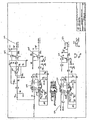
図3は、図2について説明したブロック構成要素104に相当する電源、アンテナコイルドライバ、および自動調整回路104の一例を示す。図2における電源202、コイル駆動スイッチ214、電力レベル調整部216、インピーダンス整合回路網218、および自動調整回路220に対応する回路ブロックを、それぞれ、202、214、216、218および220として図3にもっと詳しく示す。図3は回路図の一例であり、多くの回路および構成要素の変形が考えられ、それらは本発明の範囲から逸脱することなく組み込まれ得るということに留意されたい。
FIG. 3 shows an example of a power source, antenna coil driver, and
AC電源電圧は端子300および303に印加され、これらは電流をリセット可能なフューズ304に導く。そして電流は、コンデンサ305によって滑らかにされて、差動増幅器309が抵抗310を通る電流に比例して、0から5ボルトの出力を与える。一方で311および312にある抵抗が入力電圧を5ボルトにする。入力電流は、アンテナコイル駆動nMOSFETスイッチ314および315へ、そして10ボルトの電圧調整器316に供給される。この10ボルト線は、CMOSドライバ317、5ボルト電圧調整器318および他のさまざまな構成要素に供給される。5ボルト電圧調整器318は直接デジタルVccを供給し、フィルタ320を通してアナログ5ボルト319を供給する。また、フィルタ322を通して、電圧調整器318は、フィルタ324に−4.5ボルトを供給し、かつ−4.5ボルトの出力325を与える電圧インバータ323にも供給する。
The AC power supply voltage is applied to
CMOSドライバ317は、アンテナコイル駆動nMOSFETスイッチ314および315のゲートを別々に駆動する。ダイオード330およびコンデンサ332は、両方のMOSFETがnチャンネルであるので、電源レールの上にゲート駆動電圧を引き上げる。コンデンサ334および335は、ボードへ結合するキャリア周波数を最小にするようにスイッチへの低インピーダンスの電圧供給を提供する。インダクタ336は同じ理由から高周波数のスイッチングエッジを減少させる。MOSFETをまたがる内部ダイオード(図示せず)は、両方のスイッチがオフになっているときに、DC供給源あるいはグラウンドへの電流経路を提供する。
The
コンデンサ340、341および342は、並列チューニングコンデンサおよびアンテナコイルとともに、調整されたインピーダンス整合ネットワークの一部を構成する。コンデンサ340は常に決まった位置にあり、最も高いインピーダンス設定(最も低いアンテナコイル駆動電力)を表している。これに対してコンデンサ341および342は、アンテナコイルに並列か、コンデンサ340に並列に、スイッチ343および344によって切り替え可能である。このようにして、それらは共振周波数を一定に保ち、コンデンサ340と並列になったときには、アンテナコイルへの駆動インピーダンスを減少させ、与えられた電圧での電力を増加させる。これにより、アンテナコイルの調整に影響を及ぼすことなく、どの入力電圧に対しても4つの選択可能な電力設定が提供される。抵抗346および348はアンテナコイル駆動電圧を基準レベルに分割する。電力は350で送信アンテナに供給される。
トライアック360〜365およびコンデンサ366〜371は、デジタル信号によるアンテナコイルの自動調整を可能にする。コンデンサは2進シーケンスになっているので、回路は容量コンバータに対してデジタルとして振る舞う。)マイクロプロセッサによってトライアックのゲートに印加されるデジタルの組み合わせは、必要な調整値を提供するように適切なコンデンサをオンにする。共振は、デジタルアンテナコイルスイッチ信号が基準点372において出力キャリア位相に対して直角(90度)であるときに生じる。
Triacs 360-365 and capacitors 366-371 allow for automatic adjustment of the antenna coil with digital signals. Since the capacitors are in a binary sequence, the circuit behaves digitally to the capacitive converter. ) The digital combination applied to the triac gate by the microprocessor turns on the appropriate capacitors to provide the necessary adjustment values. Resonance occurs when the digital antenna coil switch signal is orthogonal (90 degrees) to the output carrier phase at the
トライアック373は、抵抗374においてたまった共振エネルギを吸収して、アンテナコイルの振動をやわらげるようにアンテナコイル電力がオフにされるときに、短い間オンにされる。読取トリガ回路375および補助入力回路376により、制御マイクロプロセッサは、自身を外部の過渡電流から保護しつつ、外部スイッチ入力に応答することが可能である。補助出力回路377においては、AUX−OUT線がローに引っ張られ、マイクロプロセッサによる外部のイベントの制御を可能にする。
図4は、図2に関して上述したブロック構成要素108に対応する受信・自動零調回路108の一例を示す。図2における自動零調回路224、受信部増幅器およびフィルタ226、復調部228、整流部230および加算回路232に対応する回路ブロックが、図4にもっと詳しく示されている。図4は回路図の一例であり、多くの回路および構成要素の変更が考えられ、それらを導入することは本発明の範囲から逸脱しないということに留意されたい。
The
FIG. 4 shows an example of a receive /
スプリッタの差動変圧器(図7において述べる)からのバランスのとられていない信号が点400で受け取られる。例えば、この信号は134.2kHZで読み取られてもよい。コンデンサ402は内部雑音の除去を提供し、増幅器404は、信号を増幅し、雑音をさらに低減すべく信号の低域を通過させる。コンデンサ406および408は、増幅器404と、インダクタ410およびコンデンサ412から構成されるタンク回路との間でインピーダンスを整合させる。これがフィルタの極を提供する。
An unbalanced signal from the splitter differential transformer (described in FIG. 7) is received at
FET(電界効果トランジスタ)414は、過渡電流を静めるべくアンテナコイル電力が除かれた後に、短くオンになる。増幅器415は、インダクタ416およびコンデンサ418から構成されるフィルタへの電圧を上昇させる。受信されたトランスポンダ信号が半二重(HDX)信号であれば、HDX信号は最後のフィルタの極の前に取り込まれ、受信されたトランスポンダ信号が全二重(FDX)信号であれば、FDX信号は422へと続く。増幅器420は、インバータ424および復調器426を駆動するゲインを提供する。
The FET (Field Effect Transistor) 414 is turned on briefly after the antenna coil power is removed to silence the transient current.
復調器426におけるCMOSスイッチは、キャリアジェネレータチップからの位相があっている方形波および方形波直角信号の位相に応じて、直接信号か間接信号かを選択する。これは、受信した信号を、キャリアと位相の合っている一つの要素と、キャリアに対して直角な一つの要素とに復調する。抵抗428および430ならびにコンデンサ432および434は、自動零調の特徴(後述する)において用いられる位相の合っている(I)要素と直交(Q)要素とを積分する。またIおよびQ信号は、増幅器436および438において整流され、増幅器440において加算される。この結果が442における復調された全二重(ベースバンドにおいて)信号であり、位相偏移変調(PSK)あるいは周波数偏移変調(FSK)の復号化(図?において説明する)への準備が整った状態である。
The CMOS switch in the
アンテナコイルの置かれた環境における小さな変化は、インピーダンスのシフトを引き起こし、したがってキャリアのフィードスルーを許すことになる。本発明は、望ましいと考えられるときに、このようなキャリアのフィードスルーを除去する自動零調という特徴を有している。回路444は、出て行くキャリアのサンプルREF_I446をとる状態可変アクティブフィルタを構成し、404における加算ジャンクションに与えられる電流出力を有するデュアル乗算型デジタル−アナログコンバータ448へIおよびQ基準電圧(I+、I−、Q+、Q−)を提供する。これらの電流は加算されて、キャリアにとは逆位相ではあるが、振幅は等しい信号を形成し、フィードスルーをゼロにする。復調器426からの出力は、OFFSET_I450およびOFFSET_Q452における電圧を測定することによって、ローカルシリアルバスに対してプロセッサ(ハウスキーピングマイクロプロセッサ、マルチプレクサによる)によって制御される。
Small changes in the environment in which the antenna coil is placed will cause an impedance shift, thus allowing carrier feedthrough. The present invention has the feature of auto-zeroing to eliminate such carrier feedthrough when deemed desirable.
図5は、図2について上述したブロック構成要素110’に対応するデコード回路110”の一例を示している。図2におけるHDXデコーダ227、PSKデコーダ240、およびFSKデコーダ242に対応する回路ブロックが図5においてより詳細に示されている。図5は回路図の一例であり、多くの回路および構成要素の変更が考えられ、それらの導入は本発明の範囲から逸脱しないということに留意されたい。
5 shows an example of a
ベースバンド信号がローパスフィルタ500およびデコーダ502の両方に与えられる。ローパスフィルタ500はコンパレータ504を駆動し、これがマイクロプロセッサのための位相偏移変調信号を二乗して、PSK_COMP506を復号する。デコーダ502は周波数偏移変調信号を復号する。電圧制御オシレータ信号は、508においてマイクロプロセッサのために二乗される。(多くのタイプの暗号化が用いられ得る。)
The baseband signal is provided to both the
半二重信号は、約124KHzと134.2KHzとの間で偏移させられながら周波数偏移変調されているので、第二段階における受信フィルタから分離されて、128KHzあたりの中心の周波数を有する位相ロックループ510に供給される。電圧制御オシレータ出力周波数は、プロセッサ610(図6)にデータクロックHDX_CAR512として与えられ、VCO制御電圧は、増幅器514によって二乗されて、データ列HDX_COMP516としてプロセッサ610(図6)に送られる。プロセッサ610(図6)は、キャリア駆動タイミングジェネレータとしても機能するが、半二重タグはキャリアがオフのときのみ読み取られるので、プロセッサ610(図6)はこの二つの機能を提供することができる。
Since the half-duplex signal is frequency shift modulated while being shifted between about 124 KHz and 134.2 KHz, it is separated from the receive filter in the second stage and has a phase with a center frequency around 128 KHz. It is supplied to the
図6は、図2について説明されたブロック構成要素102に対応するプロセッサ、メモリ、および通信回路102の一例である。図2におけるメモリ204、コントローラ206、キャリアジェネレータ208、ハウスキーピングマイクロプロセッサ210、および通信I/Oプロセッサ212が図6においてはより詳細に示されている。図6は回路図の一例であり、多くの回路および構成要素の変更が考えられ、それらの導入は本発明の範囲から逸脱しないことに留意されたい。
FIG. 6 is an example of a processor, memory, and
システムの基本的なタイミングおよび制御は、クリスタル600およびマスタマイクロプロセッサ206によって提供される。マイクロプロセッサ206は、外部の通信、他のマイクロプロセッサとの通信、音声出力、光の発生、外部制御スイッチの読み取り、受信したタグデータの復号およびフォーマット、LCD上でのデータ表示、内部EEPROM204か他の記憶装置のどちらかへのユーザオプションおよびパラメータの記憶、ならびにシステム全体の動作のやり方を一般的に保つことを容易にするソフトウェアを実行する。
The basic timing and control of the system is provided by the
ハウスキーピングマイクロプロセッサ210は、自動調整および自動零調ソフトウェアと相互作用するマルチプレクサ608を通じてアナログ電圧を測定し、リーダの内部の出来事を一般的に扱う。キャリアタイミングジェネレータ610は、キャリア(PULL_UPおよびPULL_DOWN)を発生させ、受信された信号(SQI、SQQ)を復調させるための正確なタイミング信号を提供するようにクロック周波数を分割する。また、アンテナコイル信号でビジーではないときには、先に述べたプロセッサ510とともに、半二重タグを復号する。コンパレータ612は、XORゲート614におけるSQIと比較されるゼロ交叉を検出して、プロセッサ606が図3のトライアック自動調整スイッチを制御することができるようにマルチプレクサ608において位相エラー電圧(TUN_ERR)616を発生する。
The
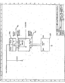
図7は、図2について上述したブロック構成要素106に対応するスプリッタおよびコイルバランス回路、ならびにアンテナコイル106の一例を示している。図2におけるスプリッタ222、コイルバランス234、ならびにアンテナコイル112および114に対応する回路ブロックは、図7においてより詳細に示されている。図7は回路図の一例であり、多くの回路および構成要素の変更が考えられ、それらの導入は本発明の範囲から逸脱しないということに留意されたい。
FIG. 7 shows an example of a splitter and coil balance circuit and
本実施形態においては、2つのアンテナコイル708を駆動する電流は、ユーザが2つのアンテナコイルを駆動する電流のバランスを等しくとることを可能にする抵抗バランスネットワーク702および調節可能な差動インダクタ706によって、バランスをとられる。差動変圧器704は、2つのアンテナコイル112および114の電流の差を測定し、これが半二重あるいは全二重トランスポンダに含まれるデータを反映し、および/あるいは磁場を通過する物体を示す。
In this embodiment, the current driving the two
本発明ではアンテナ「コイル」を上で説明しているが、コイル状であろうとなかろうと、当該分野で知られているどのようなタイプのアンテナを用いてもよいことを理解すべきである。 Although the antenna “coil” is described above in the present invention, it should be understood that any type of antenna known in the art may be used, whether coiled or not.
図3〜7の説明およびそれらの図面自体は、当業者であればさまざまな用途に応じて変更され得ることを理解するであろう代表的な回路と主要な構成要素とを示している。詳細を完全にするために、ここに付録として含まれている図3A、4A、5A、6Aおよび7Aは、図3〜7に対応する回路要素についての参照符号を含む詳細な回路図である。
発明のさまざまな実施形態を説明したが、当業者は、多くの実施形態および実装が本発明の範囲内で可能であることを理解することであろう。したがって、本発明は、添付の請求項およびそれらの等価物に鑑みること以外で、限定されることはない。
The description of FIGS. 3-7 and the drawings themselves illustrate representative circuits and major components that would be understood by one skilled in the art depending on various applications. To complete the details, FIGS. 3A, 4A, 5A, 6A and 7A, included here as appendices, are detailed circuit diagrams including reference numerals for circuit elements corresponding to FIGS.
While various embodiments of the invention have been described, those skilled in the art will appreciate that many embodiments and implementations are possible within the scope of the invention. Accordingly, the invention is not limited except in light of the attached claims and their equivalents.
100 インテロゲータ
102 プロセッサ
104 アンテナコイルドライバ/電源回路
106 スプリッタ
108 受信回路
110 デコーダ回路
112、114 アンテナコイル
202 DC電源
204 EEPROM
206 制御プロセッサ
208 キャリアジェネレータ
210 ハウスキーピングプロセッサ
212 COMM I/Oプロセッサ
214 コイルドライバスイッチ
216 電力レベル調整部
218 インピーダンス整合回路網
220 自動調整部
222 信号スプリッタ
226 受信部アンプフィルタ
227 半二重デコーダ
228 同期復調部
230 整流部
232 加算器
240、242 全二重デコーダ
300、302 端子
304 リセット可能フューズ
305 コンデンサ
309 差動増幅器
310、311、312 抵抗
314、315 アンテナコイル駆動nMOSFETスイッチ
316、318 電圧調整器
317 CMOSドライバ
320、322、324 フィルタ
323 インバータ
330 ダイオード
332、334、335 コンデンサ
336 インダクタ
340、341、342 コンデンサ
343、344 スイッ
346、348 抵抗
360〜365 トライアック
366〜371 コンデンサ
373 トライアック
374 抵抗
375 読取トリガ回路
376 補助入力回路
377 補助出力回路
402、406、408 コンデンサ
404 増幅器
410 インダクタ
412 コンデンサ
414 FET
416 インダクタ
418 コンデンサ
420 増幅器
424 インバータ
426 復調器
500 ローパスフィルタ
502 デコーダ
504 コンパレータ504
510 位相ロックループ
608 マルチプレクサ
610 キャリアタイミングジェネレータ
612 コンパレータ
DESCRIPTION OF
206
510 Phase Lock Loop 608 Multiplexer 610
Claims (6)
アンテナ駆動回路と、
第一のアンテナと、
第二のアンテナと、
前記アンテナ駆動回路によって発生された駆動電流を、前記第一のアンテナおよび前記第二のアンテナにそれぞれ向けられる実質的に同様である第一のアンテナ電流および第二のアンテナ電流に分割するように、前記アンテナ駆動回路に通信可能につながれるスプリッタ回路と、
を備え、
更に、前記スプリッタ回路は、前記第一のアンテナおよび前記第二のアンテナへの駆動信号が実質的に等価になるように前記第一のアンテナおよび前記第二のアンテナを調節するアンテナバランス回路を備えるインテロゲータ。An interrogator for a wireless identification device,
An antenna drive circuit;
The first antenna,
A second antenna,
Dividing the drive current generated by the antenna drive circuit into a first antenna current and a second antenna current that are substantially similar directed respectively to the first antenna and the second antenna; A splitter circuit communicatively coupled to the antenna drive circuit;
With
Furthermore, the splitter circuit includes an antenna balance circuit that adjusts the first antenna and the second antenna so that drive signals to the first antenna and the second antenna are substantially equivalent. Interrogator.
Applications Claiming Priority (2)
| Application Number | Priority Date | Filing Date | Title |
|---|---|---|---|
| US33799601P | 2001-11-02 | 2001-11-02 | |
| PCT/US2002/035167 WO2003040950A2 (en) | 2001-11-02 | 2002-11-01 | Dual antenna coil transponder system |
Related Child Applications (1)
| Application Number | Title | Priority Date | Filing Date |
|---|---|---|---|
| JP2006298448A Division JP4504342B2 (en) | 2001-11-02 | 2006-11-02 | Dual antenna coil transponder system |
Publications (3)
| Publication Number | Publication Date |
|---|---|
| JP2005508597A JP2005508597A (en) | 2005-03-31 |
| JP2005508597A5 JP2005508597A5 (en) | 2006-01-05 |
| JP3914537B2 true JP3914537B2 (en) | 2007-05-16 |
Family
ID=23322948
Family Applications (2)
| Application Number | Title | Priority Date | Filing Date |
|---|---|---|---|
| JP2003542507A Expired - Lifetime JP3914537B2 (en) | 2001-11-02 | 2002-11-01 | Dual antenna coil transponder system |
| JP2006298448A Expired - Lifetime JP4504342B2 (en) | 2001-11-02 | 2006-11-02 | Dual antenna coil transponder system |
Family Applications After (1)
| Application Number | Title | Priority Date | Filing Date |
|---|---|---|---|
| JP2006298448A Expired - Lifetime JP4504342B2 (en) | 2001-11-02 | 2006-11-02 | Dual antenna coil transponder system |
Country Status (14)
| Country | Link |
|---|---|
| US (1) | US7347379B2 (en) |
| EP (1) | EP1449113B1 (en) |
| JP (2) | JP3914537B2 (en) |
| KR (1) | KR100676474B1 (en) |
| AT (1) | ATE342547T1 (en) |
| AU (1) | AU2002353975B2 (en) |
| CA (1) | CA2465651C (en) |
| CY (1) | CY1106282T1 (en) |
| DE (1) | DE60215382T2 (en) |
| DK (1) | DK1449113T3 (en) |
| ES (1) | ES2272796T3 (en) |
| HK (1) | HK1069448A1 (en) |
| MX (1) | MXPA04004165A (en) |
| WO (1) | WO2003040950A2 (en) |
Families Citing this family (66)
| Publication number | Priority date | Publication date | Assignee | Title |
|---|---|---|---|---|
| US7014103B2 (en) * | 2003-06-13 | 2006-03-21 | Xtec, Incorporated | Differential radio frequency identification reader |
| US7372364B2 (en) | 2003-11-10 | 2008-05-13 | 3M Innovative Properties Company | Algorithm for RFID security |
| US7119692B2 (en) * | 2003-11-10 | 2006-10-10 | 3M Innovative Properties Company | System for detecting radio-frequency identification tags |
| US7197279B2 (en) * | 2003-12-31 | 2007-03-27 | Wj Communications, Inc. | Multiprotocol RFID reader |
| US6995729B2 (en) * | 2004-01-09 | 2006-02-07 | Biosense Webster, Inc. | Transponder with overlapping coil antennas on a common core |
| CN100573569C (en) * | 2004-09-10 | 2009-12-23 | 株式会社半导体能源研究所 | Semiconductor device |
| US7546089B2 (en) | 2004-12-23 | 2009-06-09 | Triquint Semiconductor, Inc. | Switchable directional coupler for use with RF devices |
| US20090121835A1 (en) * | 2005-03-18 | 2009-05-14 | Marc Borret | Communications Device, Apparatus and System |
| FR2883680A1 (en) * | 2005-03-23 | 2006-09-29 | Frederic Pagnol | Transponder e.g. read only transponder, information reading device for article storage device, has detection units producing signal giving receiving antenna state changes from difference between reading antenna and compensation arm voltages |
| ATE502348T1 (en) * | 2005-04-08 | 2011-04-15 | Nxp Bv | RFID READER WITH ANTENNA AND OPERATING METHOD THEREFOR |
| EP1907889B1 (en) | 2005-07-14 | 2012-04-25 | Lyngsoe Systems Ltd. | Dual loop magnetic excitation for mail tag |
| JP4313795B2 (en) * | 2005-09-30 | 2009-08-12 | 富士通マイクロエレクトロニクス株式会社 | Non-contact tag, control method of non-contact tag |
| DE102005051493A1 (en) * | 2005-10-26 | 2007-07-05 | ACG Identification Technologies Gesellschaft mbH, Grambach | Device for monitoring near-field communication with inductive transponders of electronic documents |
| US9466057B2 (en) * | 2006-05-04 | 2016-10-11 | First Data Corporation | RF presentation instrument with sensor control |
| US7683261B2 (en) * | 2006-05-19 | 2010-03-23 | Schweitzer Engineering Laboratories, Inc. | Article and method for providing a seal for an encapsulated device |
| WO2007137192A2 (en) * | 2006-05-19 | 2007-11-29 | Schweitzer Engineering Laboratories, Inc. | Apparatus and system for adjusting settings of a power system device using a magnetically coupled actuator |
| MX2008014568A (en) * | 2006-05-19 | 2008-11-28 | Schweitzer Engineering Lab Inc | Faulted circuit indicator monitoring device with wireless memory monitor. |
| US7692538B2 (en) * | 2006-05-19 | 2010-04-06 | Schweitzer Engineering Laboratories, Inc. | User interface for monitoring a plurality of faulted circuit indicators |
| US8059006B2 (en) * | 2007-05-18 | 2011-11-15 | Schweitzer Engineering Laboratories, Inc. | System and method for communicating power system information through a radio frequency device |
| MX2008014709A (en) * | 2006-05-19 | 2008-12-03 | Schweitzer Engineering Lab Inc | Magnetic probe apparatus and method for providing a wireless connection to a detection device. |
| US20070288283A1 (en) * | 2006-06-09 | 2007-12-13 | Devshop Inc. | Method for project management |
| US8344888B2 (en) * | 2006-08-31 | 2013-01-01 | Semiconductor Energy Laboratory Co., Ltd. | Semiconductor device |
| US7561107B2 (en) | 2006-09-07 | 2009-07-14 | Intelleflex Corporation | RFID device with microstrip antennas |
| DE102006046640A1 (en) * | 2006-09-29 | 2008-04-03 | Bundesdruckerei Gmbh | Radio frequency identification device reader for document, has radio frquency identification device chip, bearing surface for side of document and another bearing surface for another side of document |
| US7769345B2 (en) * | 2006-09-29 | 2010-08-03 | Sony Ericsson Mobile Communications Ab | Device and method for guiding a user to a communication position |
| DE202006015768U1 (en) * | 2006-10-14 | 2006-12-14 | Sick Ag | Monitoring system for closing doors comprises transponder mounted on door and detector coil mounted on door frame, functioning of coil being checked using second coil which reduces strength of its magnetic field |
| US10149177B2 (en) | 2006-11-18 | 2018-12-04 | Rfmicron, Inc. | Wireless sensor including an RF signal circuit |
| US12073272B2 (en) | 2006-11-18 | 2024-08-27 | Rfmicron, Inc. | Generating a response by a radio frequency identification (RFID) tag within a field strength shell of interest |
| US10715209B2 (en) | 2006-11-18 | 2020-07-14 | RF Micron, Inc. | Computing device for processing environmental sensed conditions |
| US11817637B2 (en) | 2006-11-18 | 2023-11-14 | Rfmicron, Inc. | Radio frequency identification (RFID) moisture tag(s) and sensors with extended sensing via capillaries |
| KR100772459B1 (en) * | 2007-01-24 | 2007-11-01 | 주식회사 유컴테크놀러지 | Method for reading rfid tag and rfid tag reader using the same |
| GB2445974B (en) * | 2007-01-25 | 2011-05-11 | Hewlett Packard Development Co | Apparatus for and method of selecting between antennas for wireless communication |
| DE102007032643B4 (en) * | 2007-07-11 | 2020-07-16 | Sew-Eurodrive Gmbh & Co Kg | Device for contactless power transmission, method for transmitting a data signal and system for contactless power transmission to mobile consumers |
| US20090066516A1 (en) * | 2007-09-06 | 2009-03-12 | Symbol Technologies, Inc. | Dual Mode RFID Tag Utilizing Dual Antennas |
| GB0722516D0 (en) * | 2007-11-15 | 2007-12-27 | Innovision Res & Tech Plc | Near field communication devices |
| KR100994474B1 (en) * | 2008-01-30 | 2010-11-16 | (주)블루버드 소프트 | Raido Frequency IDentification reader capable of impedance matching for preventing performance deterioration |
| TWI364895B (en) * | 2008-06-09 | 2012-05-21 | Univ Nat Taipei Technology | Wireless power transmitting apparatus |
| US8665102B2 (en) * | 2008-07-18 | 2014-03-04 | Schweitzer Engineering Laboratories Inc | Transceiver interface for power system monitoring |
| US20100062728A1 (en) * | 2008-09-05 | 2010-03-11 | Motorola, Inc, | Tuning an electrically small antenna |
| WO2010104179A1 (en) * | 2009-03-13 | 2010-09-16 | 株式会社村田製作所 | Signal processing circuit and antenna apparatus |
| US8450997B2 (en) * | 2009-04-28 | 2013-05-28 | Brown University | Electromagnetic position and orientation sensing system |
| US8472560B2 (en) | 2010-11-02 | 2013-06-25 | Securekey Technologies Inc. | Apparatus and method for detecting RFID signals |
| DE102011018633B4 (en) | 2011-04-21 | 2021-10-07 | Sew-Eurodrive Gmbh & Co Kg | System for inductive energy transmission to a consumer |
| US8526156B2 (en) | 2011-12-21 | 2013-09-03 | Schweitzer Engineering Laboratories Inc | High speed signaling of power system conditions |
| US9227641B2 (en) | 2013-05-03 | 2016-01-05 | Thales Canada Inc | Vehicle position determining system and method of using the same |
| DE102013209696A1 (en) * | 2013-05-24 | 2014-11-27 | Robert Bosch Gmbh | Phase control and phase control method |
| EP2830229B1 (en) * | 2013-07-25 | 2017-04-19 | Nxp B.V. | A multichannel transponder and a method of determining a most strongly coupled channel or more strongly coupled channels |
| KR102184679B1 (en) | 2013-12-20 | 2020-11-30 | 삼성전자주식회사 | Smart nfc antenna matching network system having multiple antennas and user device including the same |
| JP2017512110A (en) | 2014-01-24 | 2017-05-18 | エルセント メディカル,インコーポレイテッド | System and method including a localization factor |
| FI126437B (en) * | 2014-07-07 | 2016-11-30 | Metso Flow Control Oy | Additive RFID reader |
| EP3032757A3 (en) * | 2014-12-12 | 2016-10-26 | United Technologies Corporation | System and method for coil sensor design, alignment and tuning |
| US9987097B2 (en) | 2015-10-02 | 2018-06-05 | Elucent Medical, Inc. | Signal tag detection components, devices, and systems |
| US9730764B2 (en) | 2015-10-02 | 2017-08-15 | Elucent Medical, Inc. | Signal tag detection components, devices, and systems |
| JP6658070B2 (en) * | 2016-02-24 | 2020-03-04 | 株式会社村田製作所 | Multiplexer, transmitting device and receiving device |
| US10476532B2 (en) * | 2016-02-24 | 2019-11-12 | Murata Manufacturing Co., Ltd. | Multiplexer, transmission apparatus, and reception apparatus |
| DE102016008856A1 (en) * | 2016-07-20 | 2018-01-25 | Audi Ag | Method and device for the localization of radio signals |
| WO2018031826A1 (en) | 2016-08-12 | 2018-02-15 | Elucent Medical, Inc. | Surgical device guidance and monitoring devices, systems, and methods |
| US10243254B2 (en) | 2016-08-25 | 2019-03-26 | Schlage Lock Company Llc | Self adjusting antenna impedance for credential detection in an access control system |
| US10430783B2 (en) | 2016-10-03 | 2019-10-01 | Square, Inc. | Transmit phase detection circuit |
| USD812130S1 (en) | 2016-10-28 | 2018-03-06 | Square, Inc. | Electronic device |
| WO2018147848A1 (en) * | 2017-02-08 | 2018-08-16 | Empire Technology Development Llc | Signal adapters |
| US10278779B1 (en) | 2018-06-05 | 2019-05-07 | Elucent Medical, Inc. | Exciter assemblies |
| KR102640294B1 (en) | 2018-11-27 | 2024-02-22 | 삼성전자주식회사 | Near field communication circuit and operation method of the same |
| GB2582183B (en) * | 2019-03-15 | 2021-10-06 | Drayson Tech Europe Ltd | Electronics for use in smart cards and other near field RF communications enabled systems |
| US11397198B2 (en) | 2019-08-23 | 2022-07-26 | Schweitzer Engineering Laboratories, Inc. | Wireless current sensor |
| CA3194040A1 (en) * | 2021-05-20 | 2022-11-24 | Detnet South Africa (Pty) Ltd | Apparatus for use in a wireless detonator system |
Family Cites Families (18)
| Publication number | Priority date | Publication date | Assignee | Title |
|---|---|---|---|---|
| JPS5245953A (en) * | 1975-10-09 | 1977-04-12 | Nippon Steel Corp | Method for inspecting metal body by use of disturbances in blanced |
| US4361153A (en) * | 1980-05-27 | 1982-11-30 | Cordis Corporation | Implant telemetry system |
| US4500883A (en) * | 1983-03-07 | 1985-02-19 | The United States Of America As Represented By The Secretary Of The Army | Adaptive multiple interference tracking and cancelling antenna |
| US4542532A (en) * | 1984-03-09 | 1985-09-17 | Medtronic, Inc. | Dual-antenna transceiver |
| US4673943A (en) * | 1984-09-25 | 1987-06-16 | The United States Of America As Represented By The Secretary Of The Air Force | Integrated defense communications system antijamming antenna system |
| JP2882856B2 (en) * | 1990-07-04 | 1999-04-12 | 三菱マテリアル株式会社 | Eddy current flaw detector |
| US5264798A (en) * | 1991-10-29 | 1993-11-23 | The United States Of America As Represented By The Secretary Of The Navy | Autonulling AC bridge using differential and integration feedback |
| US5227803A (en) * | 1992-07-22 | 1993-07-13 | Hughes Aircraft Company | Transponder location and tracking system and method |
| EP0596521B1 (en) * | 1992-11-06 | 1998-02-11 | Texas Instruments Deutschland Gmbh | Multi-interrogator, datacom, and transponder arrangement |
| US5491715A (en) * | 1993-06-28 | 1996-02-13 | Texas Instruments Deutschland Gmbh | Automatic antenna tuning method and circuit |
| US5630835A (en) * | 1995-07-24 | 1997-05-20 | Cardiac Control Systems, Inc. | Method and apparatus for the suppression of far-field interference signals for implantable device data transmission systems |
| US6150921A (en) * | 1996-10-17 | 2000-11-21 | Pinpoint Corporation | Article tracking system |
| US5842118A (en) * | 1996-12-18 | 1998-11-24 | Micron Communications, Inc. | Communication system including diversity antenna queuing |
| JP3402989B2 (en) * | 1997-02-21 | 2003-05-06 | 三菱重工業株式会社 | Tag information reading device |
| US6307468B1 (en) * | 1999-07-20 | 2001-10-23 | Avid Identification Systems, Inc. | Impedance matching network and multidimensional electromagnetic field coil for a transponder interrogator |
| US6236315B1 (en) * | 1999-10-19 | 2001-05-22 | Lucent Technologies Inc. | Method and apparatus for improving the interrogation range of an RF tag |
| FR2802738A1 (en) * | 1999-12-15 | 2001-06-22 | Circe | TRANSPONDER READING DEVICE |
| JP2002057608A (en) * | 2000-08-08 | 2002-02-22 | Omron Corp | Data identification antenna, data identification system and method |
-
2002
- 2002-11-01 DK DK02789379T patent/DK1449113T3/en active
- 2002-11-01 AT AT02789379T patent/ATE342547T1/en active
- 2002-11-01 KR KR1020047006572A patent/KR100676474B1/en active IP Right Grant
- 2002-11-01 US US10/499,351 patent/US7347379B2/en not_active Expired - Lifetime
- 2002-11-01 ES ES02789379T patent/ES2272796T3/en not_active Expired - Lifetime
- 2002-11-01 EP EP02789379A patent/EP1449113B1/en not_active Expired - Lifetime
- 2002-11-01 WO PCT/US2002/035167 patent/WO2003040950A2/en active IP Right Grant
- 2002-11-01 CA CA2465651A patent/CA2465651C/en not_active Expired - Lifetime
- 2002-11-01 DE DE60215382T patent/DE60215382T2/en not_active Expired - Lifetime
- 2002-11-01 MX MXPA04004165A patent/MXPA04004165A/en active IP Right Grant
- 2002-11-01 AU AU2002353975A patent/AU2002353975B2/en not_active Expired
- 2002-11-01 JP JP2003542507A patent/JP3914537B2/en not_active Expired - Lifetime
-
2005
- 2005-02-22 HK HK05101474A patent/HK1069448A1/en not_active IP Right Cessation
-
2006
- 2006-11-02 JP JP2006298448A patent/JP4504342B2/en not_active Expired - Lifetime
- 2006-12-08 CY CY20061101768T patent/CY1106282T1/en unknown
Also Published As
| Publication number | Publication date |
|---|---|
| ATE342547T1 (en) | 2006-11-15 |
| MXPA04004165A (en) | 2004-07-08 |
| JP2005508597A (en) | 2005-03-31 |
| DE60215382T2 (en) | 2007-08-23 |
| KR100676474B1 (en) | 2007-02-02 |
| KR20040062606A (en) | 2004-07-07 |
| US7347379B2 (en) | 2008-03-25 |
| EP1449113A4 (en) | 2005-01-12 |
| WO2003040950A2 (en) | 2003-05-15 |
| ES2272796T3 (en) | 2007-05-01 |
| DK1449113T3 (en) | 2007-01-29 |
| EP1449113B1 (en) | 2006-10-11 |
| US20050087599A1 (en) | 2005-04-28 |
| EP1449113A2 (en) | 2004-08-25 |
| CA2465651C (en) | 2011-02-08 |
| JP2007109242A (en) | 2007-04-26 |
| JP4504342B2 (en) | 2010-07-14 |
| WO2003040950A3 (en) | 2003-09-18 |
| HK1069448A1 (en) | 2005-05-20 |
| DE60215382D1 (en) | 2006-11-23 |
| CY1106282T1 (en) | 2011-10-12 |
| AU2002353975B2 (en) | 2007-12-06 |
| CA2465651A1 (en) | 2003-05-15 |
Similar Documents
| Publication | Publication Date | Title |
|---|---|---|
| JP3914537B2 (en) | Dual antenna coil transponder system | |
| AU2002353975A1 (en) | Dual antenna coil transponder system | |
| KR100226117B1 (en) | Proximity detecting apparatus | |
| US9756579B2 (en) | Near field communication system and method for controlling transmission power of near field communication system | |
| US6650226B1 (en) | Detection, by an electromagnetic transponder reader, of the distance separating it from a transponder | |
| US8319612B2 (en) | Transponder detector for an RFID system generating a progression of detection signals | |
| US6307468B1 (en) | Impedance matching network and multidimensional electromagnetic field coil for a transponder interrogator | |
| US20070171992A1 (en) | Near field RFID system with multiple reader coils | |
| JP5023965B2 (en) | Reader / writer device and non-contact data carrier system | |
| EP0829940A2 (en) | Power transmission system, IC card and information communication system using IC card | |
| US20090002175A1 (en) | Power Transfer for Transponder Devices | |
| JP4332963B2 (en) | Capacitive modulation of electromagnetic transponders | |
| KR20070076071A (en) | Contactless card and contactless card system | |
| US20080180224A1 (en) | Apparatus and method for providing a supply voltage and a load modulation in a transponder | |
| WO2001067413A1 (en) | Electrostatic and electromagnetic communication systems and combinations thereof | |
| IL100451A (en) | Non-contact data communications system | |
| JP3968948B2 (en) | Detection of distance from electromagnetic transponder | |
| US6320508B1 (en) | Arrangement for an antenna resonant circuit for contactless transmission systems | |
| US10873358B1 (en) | Card read response method, apparatus, and system, and signal transceiving device | |
| JP2005063123A (en) | Reader/writer device for non-contact card and method for automatically adjusting its antenna natural frequency, and program | |
| JP3579899B2 (en) | IC card reader / writer | |
| KR20040060577A (en) | voltage limit circuit layout for use in RF-ID card based on CMOS | |
| JP3990100B2 (en) | Non-contact information recording medium | |
| JP2006146539A (en) | Noncontact ic card reader and/or writer device | |
| Chesaru et al. | RFID 13.56 MHz transponder IC frontend |
Legal Events
| Date | Code | Title | Description |
|---|---|---|---|
| A621 | Written request for application examination |
Free format text: JAPANESE INTERMEDIATE CODE: A621 Effective date: 20050824 |
|
| A521 | Request for written amendment filed |
Free format text: JAPANESE INTERMEDIATE CODE: A523 Effective date: 20050829 |
|
| A871 | Explanation of circumstances concerning accelerated examination |
Free format text: JAPANESE INTERMEDIATE CODE: A871 Effective date: 20050913 |
|
| A975 | Report on accelerated examination |
Free format text: JAPANESE INTERMEDIATE CODE: A971005 Effective date: 20051025 |
|
| A131 | Notification of reasons for refusal |
Free format text: JAPANESE INTERMEDIATE CODE: A131 Effective date: 20060110 |
|
| A601 | Written request for extension of time |
Free format text: JAPANESE INTERMEDIATE CODE: A601 Effective date: 20060406 |
|
| A602 | Written permission of extension of time |
Free format text: JAPANESE INTERMEDIATE CODE: A602 Effective date: 20060413 |
|
| A521 | Request for written amendment filed |
Free format text: JAPANESE INTERMEDIATE CODE: A523 Effective date: 20060705 |
|
| A02 | Decision of refusal |
Free format text: JAPANESE INTERMEDIATE CODE: A02 Effective date: 20060808 |
|
| A521 | Request for written amendment filed |
Free format text: JAPANESE INTERMEDIATE CODE: A523 Effective date: 20061102 |
|
| A521 | Request for written amendment filed |
Free format text: JAPANESE INTERMEDIATE CODE: A523 Effective date: 20061124 |
|
| A911 | Transfer to examiner for re-examination before appeal (zenchi) |
Free format text: JAPANESE INTERMEDIATE CODE: A911 Effective date: 20061219 |
|
| TRDD | Decision of grant or rejection written | ||
| A01 | Written decision to grant a patent or to grant a registration (utility model) |
Free format text: JAPANESE INTERMEDIATE CODE: A01 Effective date: 20070116 |
|
| A61 | First payment of annual fees (during grant procedure) |
Free format text: JAPANESE INTERMEDIATE CODE: A61 Effective date: 20070202 |
|
| R150 | Certificate of patent or registration of utility model |
Free format text: JAPANESE INTERMEDIATE CODE: R150 Ref document number: 3914537 Country of ref document: JP Free format text: JAPANESE INTERMEDIATE CODE: R150 |
|
| FPAY | Renewal fee payment (event date is renewal date of database) |
Free format text: PAYMENT UNTIL: 20130209 Year of fee payment: 6 |
|
| R250 | Receipt of annual fees |
Free format text: JAPANESE INTERMEDIATE CODE: R250 |
|
| FPAY | Renewal fee payment (event date is renewal date of database) |
Free format text: PAYMENT UNTIL: 20160209 Year of fee payment: 9 |
|
| R250 | Receipt of annual fees |
Free format text: JAPANESE INTERMEDIATE CODE: R250 |
|
| R250 | Receipt of annual fees |
Free format text: JAPANESE INTERMEDIATE CODE: R250 |
|
| R250 | Receipt of annual fees |
Free format text: JAPANESE INTERMEDIATE CODE: R250 |
|
| R250 | Receipt of annual fees |
Free format text: JAPANESE INTERMEDIATE CODE: R250 |
|
| R250 | Receipt of annual fees |
Free format text: JAPANESE INTERMEDIATE CODE: R250 |
|
| R250 | Receipt of annual fees |
Free format text: JAPANESE INTERMEDIATE CODE: R250 |
|
| R250 | Receipt of annual fees |
Free format text: JAPANESE INTERMEDIATE CODE: R250 |
|
| R250 | Receipt of annual fees |
Free format text: JAPANESE INTERMEDIATE CODE: R250 |
|
| EXPY | Cancellation because of completion of term |