JP3906418B2 - Magnetic field generator for MRI - Google Patents
Magnetic field generator for MRI Download PDFInfo
- Publication number
- JP3906418B2 JP3906418B2 JP24406896A JP24406896A JP3906418B2 JP 3906418 B2 JP3906418 B2 JP 3906418B2 JP 24406896 A JP24406896 A JP 24406896A JP 24406896 A JP24406896 A JP 24406896A JP 3906418 B2 JP3906418 B2 JP 3906418B2
- Authority
- JP
- Japan
- Prior art keywords
- magnetic field
- magnetic
- holder
- mri
- gap
- Prior art date
- Legal status (The legal status is an assumption and is not a legal conclusion. Google has not performed a legal analysis and makes no representation as to the accuracy of the status listed.)
- Expired - Lifetime
Links
Images

Classifications
-
- G—PHYSICS
- G01—MEASURING; TESTING
- G01R—MEASURING ELECTRIC VARIABLES; MEASURING MAGNETIC VARIABLES
- G01R33/00—Arrangements or instruments for measuring magnetic variables
- G01R33/20—Arrangements or instruments for measuring magnetic variables involving magnetic resonance
- G01R33/28—Details of apparatus provided for in groups G01R33/44 - G01R33/64
- G01R33/38—Systems for generation, homogenisation or stabilisation of the main or gradient magnetic field
- G01R33/387—Compensation of inhomogeneities
- G01R33/3873—Compensation of inhomogeneities using ferromagnetic bodies ; Passive shimming
Description
【0001】
【発明の属する技術分野】
この発明は、医療用磁気共鳴断層撮影装置(以下MRIという)等に用いられる磁界発生装置の改良に係り、空隙を形成して対向する一対の磁極片に傾斜磁界コイルを装着して当該磁界発生装置を設置した後、設置した環境の影響等によって磁界の調整を図る場合、傾斜磁界コイルを脱着することなく容易に空隙内の撮像視野内の磁界均一度の調整を可能にしたMRI用磁界発生装置に関する。
【0002】
【従来の技術】
医療用磁気共鳴断層撮影装置(以下MRIという)は、強力な磁界を形成する磁界発生装置の空隙内に、被検者の一部または全部を挿入して、対象物の断層イメージを得てその組織の性質まで描き出すことができる装置である。
上記MRI用の磁界発生装置において、空隙は被検者の一部または全部が挿入できるだけの広さが必要であり、かつ鮮明な断層イメージを得るために、通常、空隙内の撮像視野内には、0.02〜2.0Tでかつ1×10⁻⁴以下の精度を有する安定した強力な均一磁界を形成することが要求される。
【0003】
MRIに用いる磁界発生装置として、磁界発生源としてR−Fe−B系磁石を用いた一対の永久磁石構成体の各々の一方端に磁極片を固着して対向させ、他方端を継鉄にて連結し、磁極片間の空隙内に、静磁界を発生させる構成が知られている(特公平2−23010号公報)。
【0004】
また、磁界発生源として、上記の永久磁石構成体に換えて、鉄心の周囲に電磁コイル(常伝導コイル、超伝導コイル等を含む)を巻回配置した構成のものも知られており(特開平4−288137号公報)、これらの構成においても上記と同様な磁極片を採用している。
【0005】
磁界発生装置の磁界の均一度は、前述した如く、所定空間内で1×10⁻⁴以下の精度が要求されるが、特に磁気回路における磁極片の形状による影響が大きく、また継鉄の形状や配置箇所などにより影響を受け、撮像視野内の磁界均一度を所定値にとなすために種々の調整が不可避であるため、磁極片を再加工することなく、所要空隙内の磁界強度を局部的に所定量だけ増減でき、極めて高い均一度の磁界を得る構成が必要であった。
【0006】
そこで、出願人は、撮像空間を球体として想定し、該球体空間を複数の水平面で横断して測定した各円周上の磁界強度の強弱に応じて、磁極片の空隙対向面の所定位置に磁性材小片及び/又は永久磁石小片を配置することによって、磁極片を加工する必要がなく、空隙内の磁界強度を局部的に所要量だけ増減でき、磁界均一度を向上させることができることを提案(特公平5−87962号)した。
【0007】
【発明が解決しようとする課題】
MRIでは、空隙内の位置情報を得るために、通常X、Y、Zの3方向に対応する3組のコイル群からなる傾斜磁界コイル(GC)が各磁極片の近傍に配置され、この傾斜磁界コイルにパルス電流を印加することによって、空隙内に所望方向の傾斜磁界を発生することができる。つまり、空隙内に形成されている均一な磁界に傾斜磁界を加えることによって核磁気共鳴の信号に位置情報を与えるものであり、一つの画像を得るためには多数のパルス状傾斜磁界を加えることが必要となる。
【0008】
一方、MRIをすでに現場に設置した場合や設置した環境の影響等によって磁界の調整を図る場合があるが、磁極片に傾斜磁界コイルを設置した後では、上記のように磁性材小片及び/又は永久磁石小片を配置、移動させて磁界均一度を調整することは作業が複雑かつ困難であり、短時間で作業を完了することは不可能である。
【0009】
MRI用磁界発生装置において、磁界均一度の調整のために磁界調整用永久磁石小片を配置する方法として、特開平1−164356号には、複数の磁界調整用永久磁石小片を台座を介してビスで固定した保持板を、永久磁石小片を磁極片側にして磁極片の環状突起にボルト止めしたり、一対の磁極片の外周側から空隙に対して配置する方法が提案されている。この構成では、保持板に永久磁石小片を台座を介してビスで固定するため、シムの脱着に大変な手間を要する問題がある。
【0010】
すなわち、磁界均一度の調整のための磁性材小片あるいは永久磁石小片は同一形状寸法からなるものでなく、まず、調整のための空間位置や調整量に応じて磁性材か永久磁石が選定され、さらにその形状・寸法も適宜選定されるため、保持板に台座を介してビスで固定するには磁性材の形状・寸法に応じた台座を作成する必要があり、また、永久磁石小片はその磁化方向を特定方向に向けるために形状・寸法に応じて所要形状の台座を作成する必要があり、シムの脱着には台座の作成を含めて大変な手間を要する問題がある。
【0011】
この発明は、一対の磁極片に傾斜磁界コイルを装着してMRI用磁界発生装置を設置した後、傾斜磁界コイルを脱着することなく、安全かつ容易に空隙の撮像視野内の磁界均一度の調整を可能にしたMRI用磁界発生装置の提供を目的としている。
【0012】
【課題を解決するための手段】
発明者らは、MRI用磁界発生装置の設置後の傾斜磁界コイルを脱着することなく、空隙の撮像視野内の磁界均一度の調整を容易にかつ確実に行うことができる磁界発生装置の構成を目的に種々検討した結果、磁性小片を収納可能なピットが配設された本体と空隙側へ脱着自在の蓋とからなるシムホルダーを用いることにより、種々形状、寸法、磁化方向を有する磁性材小片あるいは永久磁石小片の配設が、本体のピットに入れて必要に応じてスペーサーを介して蓋をするだけで目的が達成できることを知見し、この発明を完成した。
【0013】
この発明は、空隙を形成して対向する一対の磁極片を有し、該空隙に磁界を発生させるMRI用磁界発生装置において、各磁極片の空隙対向面の所定位置に磁界均一度調整用磁性小片を配置するとともに、当該各磁極片に対向配置する傾斜磁界コイルの空隙対向面に非磁性からなるシムホルダーを着脱可能に配置した構成からなり、前記シムホルダーは、ベース円盤と、磁界均一度調整用磁性小片を収納するための複数の孔部を穿孔配置したホルダー円盤とからなるホルダー本体と、空隙側へ着脱自在の蓋用円盤との積層構造を有し、かつ前記ホルダー円盤の複数の孔部は、空隙中央部に想定される球体空間を複数の水平面で横断した場合の各々水平面におけるそれぞれの円周上の各位置に対応するように同心円状に穿孔配置され、前記磁界均一度調整用磁性小片をホルダー円盤の所要孔部に収納配置した後、傾斜磁界コイルの空隙対向面側に配置することを特徴とするMRI用磁界発生装置である。
【0014】
【発明の実施の形態】
以下に、この発明によるMRI用磁界発生装置の構成例を図面に基づいて詳述する。図1はこの発明による磁界発生装置の磁極片の一実施例を示す縦断面図である。図2はこの発明によるシムホルダーの分解斜視図である。なお、ピットの大きさは図示のため誇張拡大してある。
【0015】
図1の磁極片2は、上下に対向配置される一対のうち下側の磁極片を示すもので、R-Fe-B系磁石あるいは電磁コイルなどの磁界発生源としての磁石構成体1の上に載置されている。磁極片2は、鉄あるいは軟鉄からなるベース部3の外周部に純鉄製の環状突起部4を配置し、中心部は鉄あるいは軟鉄、積層けい素鋼板あるいはソフトフェライトからなり、また、平坦凸状突起部5を配置してある。
【0016】
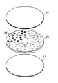
また、図1の符号6は傾斜磁界コイルであり、図示しない支持部材で磁極片2内の所要位置に配設してある。この傾斜磁界コイル6またはその支持部材に止着するようにシムホルダー10が設けてある。シムホルダー10は、図2に示すごとく、3層の非磁性の薄板円盤からなるもので、ベース円盤11と磁性小片を収納するためのピットとなる孔部12を穿孔配置したホルダー円盤13と、蓋用円盤14の各薄板の積層構造からなる。磁性小片を収納するための孔部12は、空隙中央部に想定される球体空間を複数の水平面で横断した場合の各々水平面におけるそれぞれの円周上の各位置に対応して磁性小片が配置されるように、ホルダー円盤13に同心円状に穿孔配置される。
【0017】
シムホルダー10を構成する各円盤は、適宜配置されるねじにて止着される。すまわち、ベース円盤11上にホルダー円盤13が積層されて止着されたのち、所定パターンで配置されたピットの所要箇所に磁界均一度の調整のための磁性材小片あるいは永久磁石小片が挿入され、必要に応じてピット内の蓋用円盤14との隙間にスペーサーを入れて位置決めを行った後、蓋用円盤14をねじ止めして積層されて一体となったシムホルダー10を、傾斜磁界コイル6またはその支持部材に位置合わせを行って止着する。
【0018】
この発明において、シムホルダー10には、塩化ビニル樹脂、ガラス繊維強化プラスチックなどの非磁性材が使用でき、図2の3層構造のほか、ピットが配設された本体と蓋の2層構造であってもよい。
【0019】
【実施例】
材料に塩化ビニル樹脂を用いて、図2に示す3層構造のシムホルダーを作成したところ、直径約900mm、厚み約15mmで11kg程度と軽量で取扱いが容易で、傾斜磁界コイルを磁極片間の所要位置に装着したままでシムホルダーのみの脱着が可能であった。シムホルダーを使用することにより、MRI用磁界発生装置を設営した屋内の装置サイドで線形計画法の手法を用いて磁界調整を行うことができ、磁界調整の工数が少なく、従来のいずれの方法よりも短時間で調整を完了することができた。
【0020】
【発明の効果】
この発明によるはシムホルダーは、一対の磁極片に傾斜磁界コイルを装着してMRI用磁界発生装置を設置した後、傾斜磁界コイルを脱着することなく、装置サイドで線形計画法等の手法を用いて磁界調整を行うことができ、しかも安全で容易に空隙の撮像視野内の磁界均一度の調整が可能になった。
【図面の簡単な説明】
【図1】この発明による磁界発生装置の磁極片の一実施例を示す縦断面図である。
【図2】この発明によるシムホルダーの分解斜視図である。
【符号の説明】
1 磁石構成体
2 磁極片
3 ベース
4 環状突起部
5 平坦凸状突起部
6 傾斜磁界コイル
10 シムホルダー
11 ベース円盤
12 孔部
13 ホルダー円盤
14 蓋用円盤[0001]
BACKGROUND OF THE INVENTION
The present invention relates to an improvement in a magnetic field generator used in a medical magnetic resonance tomography apparatus (hereinafter referred to as MRI) and the like, and a magnetic field is generated by mounting a gradient magnetic field coil on a pair of opposing magnetic pole pieces forming a gap. After installing the device, when adjusting the magnetic field due to the influence of the installed environment, etc., magnetic field generation for MRI that can easily adjust the magnetic field uniformity in the imaging field of view in the air gap without removing the gradient coil Relates to the device.
[0002]
[Prior art]
A medical magnetic resonance tomography apparatus (hereinafter referred to as MRI) inserts a part or all of a subject into a gap of a magnetic field generator that forms a strong magnetic field, obtains a tomographic image of an object, and It is a device that can depict the nature of the organization.
In the magnetic field generator for MRI described above, the gap needs to be wide enough to allow a part or all of the subject to be inserted. In order to obtain a clear tomographic image, the gap is usually within the imaging field of view within the gap. Therefore, it is required to form a stable and strong uniform magnetic field having an accuracy of 0.02 to 2.0 T and 1 × 10 −4 or less.
[0003]
As a magnetic field generator used for MRI, a pole piece is fixed to one end of each of a pair of permanent magnet structures using R-Fe-B magnets as a magnetic field generating source, and the other end is made of a yoke. A configuration is known in which a static magnetic field is generated in the gap between the pole pieces (Japanese Patent Publication No. 223010).
[0004]
In addition, as a magnetic field generation source, a configuration in which an electromagnetic coil (including a normal conductive coil, a superconductive coil, etc.) is wound around an iron core instead of the above-described permanent magnet structure is also known (special feature). (Kaihei 4-288137) and these configurations also employ the same pole pieces as described above.
[0005]
As described above, the uniformity of the magnetic field of the magnetic field generator is required to have an accuracy of 1 × 10 −4 or less in a predetermined space, but it is particularly affected by the shape of the magnetic pole piece in the magnetic circuit, and the shape of the yoke Since various adjustments are inevitable in order to make the magnetic field uniformity within the imaging field of view a predetermined value, the magnetic field strength in the required air gap can be localized without reworking the pole pieces. Therefore, a configuration that can increase or decrease by a predetermined amount and obtain a magnetic field with extremely high uniformity is required.
[0006]
Therefore, the applicant assumes that the imaging space is a sphere, and at a predetermined position on the air gap facing surface of the pole piece according to the strength of the magnetic field strength on each circumference measured across the sphere space by a plurality of horizontal planes. By arranging magnetic material pieces and / or permanent magnet pieces, there is no need to process the pole pieces, the magnetic field strength in the air gap can be locally increased or decreased by a required amount, and the magnetic field uniformity can be improved. (Japanese Patent Publication No. 5-87962).
[0007]
[Problems to be solved by the invention]
In MRI, in order to obtain positional information in the air gap, a gradient magnetic field coil (GC) consisting of three groups of coils corresponding to the three directions of X, Y, and Z is generally arranged near each pole piece. By applying a pulse current to the magnetic field coil, a gradient magnetic field in a desired direction can be generated in the gap. In other words, position information is given to the nuclear magnetic resonance signal by applying a gradient magnetic field to the uniform magnetic field formed in the air gap, and in order to obtain one image, a large number of pulsed gradient magnetic fields are added. Is required.
[0008]
On the other hand, there are cases where the MRI is already installed in the field or the magnetic field may be adjusted due to the influence of the installed environment. However, after the gradient magnetic field coil is installed in the magnetic pole piece, as described above, the magnetic material piece and / or It is complicated and difficult to adjust the magnetic field uniformity by arranging and moving the permanent magnet pieces, and it is impossible to complete the work in a short time.
[0009]
In a magnetic field generator for MRI, as a method of arranging magnetic field adjusting permanent magnet pieces for adjusting the magnetic field uniformity, Japanese Patent Application Laid-Open No. 1-164356 discloses a plurality of magnetic field adjusting permanent magnet pieces through screws. A method has been proposed in which the holding plate fixed in (1) is bolted to the annular protrusion of the magnetic pole piece with the small permanent magnet piece side of the magnetic pole piece, or arranged with respect to the gap from the outer peripheral side of the pair of magnetic pole pieces. In this configuration, since the permanent magnet pieces are fixed to the holding plate with screws via the pedestal, there is a problem that it takes a lot of labor to remove and install the shim.
[0010]
That is, the magnetic material piece or permanent magnet piece for adjusting the magnetic field uniformity is not composed of the same shape and dimension, and first, a magnetic material or a permanent magnet is selected according to the spatial position and adjustment amount for adjustment, Furthermore, since the shape and dimensions are also selected as appropriate, it is necessary to create a pedestal according to the shape and dimensions of the magnetic material in order to fix it to the holding plate with screws via the pedestal. In order to direct the direction to a specific direction, it is necessary to create a pedestal having a required shape in accordance with the shape and dimensions.
[0011]
The present invention adjusts the magnetic field uniformity in the imaging field of the air gap safely and easily without attaching or removing the gradient magnetic field coil after installing the magnetic field generator for MRI by mounting the gradient magnetic field coil on a pair of magnetic pole pieces. An object of the present invention is to provide a magnetic field generator for MRI that enables the above.
[0012]
[Means for Solving the Problems]
The inventors have configured a magnetic field generator that can easily and reliably adjust the magnetic field uniformity in the imaging field of the air gap without removing the gradient magnetic field coil after the installation of the magnetic field generator for MRI. As a result of various examinations for the purpose, a small piece of magnetic material having various shapes, dimensions, and magnetization directions by using a shim holder comprising a main body provided with a pit capable of accommodating a small magnetic piece and a lid detachable to the gap side. Alternatively, the inventors have found that the purpose of the permanent magnet pieces can be achieved simply by putting them in the pits of the main body and covering them with a spacer as required, thereby completing the present invention.
[0013]
This invention has a pair of pole pieces which face each other to form a gap, in the MRI magnetic field generating device for generating a magnetic field in the air gap, the magnetic field homogeneity adjusting magnetic at a predetermined position of the gap facing surfaces of each pole piece A small piece is disposed, and a non-magnetic shim holder is detachably disposed on the air gap facing surface of the gradient magnetic field coil opposed to each magnetic pole piece. The shim holder includes a base disk and a magnetic field uniformity. It has a laminated structure of a holder main body composed of a holder disk in which a plurality of holes for accommodating a magnetic piece for adjustment are perforated and a lid disk detachably attached to the gap side, and a plurality of the holder disks The holes are concentrically arranged so as to correspond to the respective positions on the respective circumferences in the horizontal plane when the spherical space assumed in the center of the gap is crossed by a plurality of horizontal planes, and the magnetic field uniform After storing place the adjustment magnetic pieces to the required hole of the holder disc, a magnetic field generator for MRI, characterized in that arranged in the air gap face opposing gradient coils.
[0014]
DETAILED DESCRIPTION OF THE INVENTION
Hereinafter, a configuration example of the magnetic field generator for MRI according to the present invention will be described in detail with reference to the drawings. FIG. 1 is a longitudinal sectional view showing an embodiment of a magnetic pole piece of a magnetic field generator according to the present invention. FIG. 2 is an exploded perspective view of the shim holder according to the present invention. Note that the size of the pits is exaggerated and enlarged for illustration.
[0015]
The pole piece 2 in FIG. 1 shows the lower pole piece of a pair opposed to each other in the vertical direction, and is an upper part of the magnet structure 1 as a magnetic field generation source such as an R-Fe-B magnet or an electromagnetic coil. Is placed. Pole pieces 2, the outer peripheral portion of the
[0016]
[0017]
Each disk constituting the
[0018]
In this invention, the
[0019]
【Example】
A shim holder with a three-layer structure shown in Fig. 2 was made using vinyl chloride resin as the material. It was about 900 mm in diameter and about 15 kg in thickness and was about 11 kg lightweight and easy to handle . Only the shim holder can be attached and detached while it is mounted in the required position . By using a shim holder, magnetic field adjustment can be performed using the linear programming method on the side of the indoor unit where the MRI magnetic field generator is installed, and the number of steps for magnetic field adjustment is small. Even the adjustment was completed in a short time.
[0020]
【The invention's effect】
According to the present invention, the shim holder uses a method such as linear programming on the apparatus side without attaching and removing the gradient magnetic field coil after installing the magnetic field generator for MRI by mounting the gradient magnetic field coil on a pair of magnetic pole pieces. The magnetic field can be adjusted and the uniformity of the magnetic field in the imaging field of the air gap can be adjusted safely and easily.
[Brief description of the drawings]
FIG. 1 is a longitudinal sectional view showing an embodiment of a pole piece of a magnetic field generator according to the present invention.
FIG. 2 is an exploded perspective view of a shim holder according to the present invention.
[Explanation of symbols]
DESCRIPTION OF SYMBOLS 1 Magnet structure 2
Claims (1)
Priority Applications (2)
| Application Number | Priority Date | Filing Date | Title |
|---|---|---|---|
| JP24406896A JP3906418B2 (en) | 1996-08-26 | 1996-08-26 | Magnetic field generator for MRI |
| PCT/JP1997/004867 WO1999033397A1 (en) | 1996-08-26 | 1997-12-26 | Mri magnetic field generator |
Applications Claiming Priority (2)
| Application Number | Priority Date | Filing Date | Title |
|---|---|---|---|
| JP24406896A JP3906418B2 (en) | 1996-08-26 | 1996-08-26 | Magnetic field generator for MRI |
| PCT/JP1997/004867 WO1999033397A1 (en) | 1996-08-26 | 1997-12-26 | Mri magnetic field generator |
Publications (2)
| Publication Number | Publication Date |
|---|---|
| JPH1070027A JPH1070027A (en) | 1998-03-10 |
| JP3906418B2 true JP3906418B2 (en) | 2007-04-18 |
Family
ID=26438254
Family Applications (1)
| Application Number | Title | Priority Date | Filing Date |
|---|---|---|---|
| JP24406896A Expired - Lifetime JP3906418B2 (en) | 1996-08-26 | 1996-08-26 | Magnetic field generator for MRI |
Country Status (1)
| Country | Link |
|---|---|
| JP (1) | JP3906418B2 (en) |
Families Citing this family (3)
| Publication number | Priority date | Publication date | Assignee | Title |
|---|---|---|---|---|
| US5923235A (en) * | 1998-10-23 | 1999-07-13 | General Electric Company | Shim assembly for a pole face of a magnet |
| JP2002165773A (en) * | 2000-11-29 | 2002-06-11 | Ge Medical Systems Global Technology Co Llc | Method of unifying static magnetic field and mri apparatus |
| JP2005261806A (en) * | 2004-03-22 | 2005-09-29 | Hitachi Medical Corp | Magnetic resonance imaging apparatus |
-
1996
- 1996-08-26 JP JP24406896A patent/JP3906418B2/en not_active Expired - Lifetime
Also Published As
| Publication number | Publication date |
|---|---|
| JPH1070027A (en) | 1998-03-10 |
Similar Documents
| Publication | Publication Date | Title |
|---|---|---|
| US6275128B1 (en) | MRI magnetic field generator | |
| US11215685B2 (en) | B0 magnet methods and apparatus for a magnetic resonance imaging system | |
| EP0760484B1 (en) | Opposed magnet-type magnetic circuit assembly with permanent magnets | |
| JP2839114B2 (en) | Permanent magnet for nuclear magnetic resonance imaging equipment | |
| US5134374A (en) | Magnetic field control apparatus | |
| JP4826929B2 (en) | Magnetic field generator | |
| US6794973B1 (en) | Magnetic field generating device for MRI | |
| US4980641A (en) | Method and apparatus of reducing magnetic hysteresis in MRI systems | |
| US7071694B1 (en) | Magnet assembly of an MRI system with concentric annular ferromagnetic laminations | |
| EP1154280A2 (en) | Magnetic resonance apparatus including rose ring | |
| JPH03131234A (en) | Equipment for generating magnetic field for mri | |
| JPH041481B2 (en) | ||
| US5414399A (en) | Open access superconducting MRI magnet having an apparatus for reducing magnetic hysteresis in superconducting MRI systems | |
| WO2010080350A2 (en) | Compact inhomogeneous permanent magnetic field generator for magnetic resonance imaging | |
| JP3733441B1 (en) | Magnetic resonance imaging apparatus and magnet apparatus thereof | |
| US6498488B2 (en) | Magnetic resonance imaging apparatus | |
| JP2002034947A (en) | Magnet device and mri apparatus using the same | |
| JP3906418B2 (en) | Magnetic field generator for MRI | |
| JP2000083924A (en) | Magnetic resonance imaging method | |
| JP3151129B2 (en) | Permanent magnet permanent magnet magnetic circuit and its magnetic field adjustment method | |
| JP3372098B2 (en) | Static magnetic field generator for magnetic resonance imaging | |
| JP2000357608A (en) | Magnetic field generator | |
| JP2002102205A (en) | Magnetic resonace imaging apparatus | |
| JPH0394733A (en) | Magnetic field generator for mri | |
| JPH0422337A (en) | Magnetic field generating device |
Legal Events
| Date | Code | Title | Description |
|---|---|---|---|
| A131 | Notification of reasons for refusal |
Free format text: JAPANESE INTERMEDIATE CODE: A131 Effective date: 20060126 |
|
| A521 | Written amendment |
Free format text: JAPANESE INTERMEDIATE CODE: A523 Effective date: 20060327 |
|
| A131 | Notification of reasons for refusal |
Free format text: JAPANESE INTERMEDIATE CODE: A131 Effective date: 20060501 |
|
| A521 | Written amendment |
Free format text: JAPANESE INTERMEDIATE CODE: A523 Effective date: 20060627 |
|
| A02 | Decision of refusal |
Free format text: JAPANESE INTERMEDIATE CODE: A02 Effective date: 20060803 |
|
| A521 | Written amendment |
Free format text: JAPANESE INTERMEDIATE CODE: A523 Effective date: 20061004 |
|
| A911 | Transfer of reconsideration by examiner before appeal (zenchi) |
Free format text: JAPANESE INTERMEDIATE CODE: A911 Effective date: 20061106 |
|
| TRDD | Decision of grant or rejection written | ||
| A01 | Written decision to grant a patent or to grant a registration (utility model) |
Free format text: JAPANESE INTERMEDIATE CODE: A01 Effective date: 20061207 |
|
| A61 | First payment of annual fees (during grant procedure) |
Free format text: JAPANESE INTERMEDIATE CODE: A61 Effective date: 20061228 |
|
| R150 | Certificate of patent or registration of utility model |
Free format text: JAPANESE INTERMEDIATE CODE: R150 |
|
| FPAY | Renewal fee payment (event date is renewal date of database) |
Free format text: PAYMENT UNTIL: 20100126 Year of fee payment: 3 |
|
| S111 | Request for change of ownership or part of ownership |
Free format text: JAPANESE INTERMEDIATE CODE: R313115 |
|
| FPAY | Renewal fee payment (event date is renewal date of database) |
Free format text: PAYMENT UNTIL: 20100126 Year of fee payment: 3 |
|
| R350 | Written notification of registration of transfer |
Free format text: JAPANESE INTERMEDIATE CODE: R350 |
|
| FPAY | Renewal fee payment (event date is renewal date of database) |
Free format text: PAYMENT UNTIL: 20110126 Year of fee payment: 4 |
|
| FPAY | Renewal fee payment (event date is renewal date of database) |
Free format text: PAYMENT UNTIL: 20110126 Year of fee payment: 4 |
|
| FPAY | Renewal fee payment (event date is renewal date of database) |
Free format text: PAYMENT UNTIL: 20120126 Year of fee payment: 5 |
|
| FPAY | Renewal fee payment (event date is renewal date of database) |
Free format text: PAYMENT UNTIL: 20120126 Year of fee payment: 5 |
|
| FPAY | Renewal fee payment (event date is renewal date of database) |
Free format text: PAYMENT UNTIL: 20130126 Year of fee payment: 6 |
|
| FPAY | Renewal fee payment (event date is renewal date of database) |
Free format text: PAYMENT UNTIL: 20130126 Year of fee payment: 6 |
|
| FPAY | Renewal fee payment (event date is renewal date of database) |
Free format text: PAYMENT UNTIL: 20140126 Year of fee payment: 7 |
|
| R250 | Receipt of annual fees |
Free format text: JAPANESE INTERMEDIATE CODE: R250 |
|
| R250 | Receipt of annual fees |
Free format text: JAPANESE INTERMEDIATE CODE: R250 |
|
| R250 | Receipt of annual fees |
Free format text: JAPANESE INTERMEDIATE CODE: R250 |
|
| EXPY | Cancellation because of completion of term |