JP3904644B2 - Burner used for heat generator - Google Patents
Burner used for heat generator Download PDFInfo
- Publication number
- JP3904644B2 JP3904644B2 JP33972796A JP33972796A JP3904644B2 JP 3904644 B2 JP3904644 B2 JP 3904644B2 JP 33972796 A JP33972796 A JP 33972796A JP 33972796 A JP33972796 A JP 33972796A JP 3904644 B2 JP3904644 B2 JP 3904644B2
- Authority
- JP
- Japan
- Prior art keywords
- flow
- burner
- section
- burner according
- fuel
- Prior art date
- Legal status (The legal status is an assumption and is not a legal conclusion. Google has not performed a legal analysis and makes no representation as to the accuracy of the status listed.)
- Expired - Lifetime
Links
Images


Classifications
-
- F—MECHANICAL ENGINEERING; LIGHTING; HEATING; WEAPONS; BLASTING
- F23—COMBUSTION APPARATUS; COMBUSTION PROCESSES
- F23D—BURNERS
- F23D17/00—Burners for combustion simultaneously or alternately of gaseous or liquid or pulverulent fuel
- F23D17/002—Burners for combustion simultaneously or alternately of gaseous or liquid or pulverulent fuel gaseous or liquid fuel
-
- F—MECHANICAL ENGINEERING; LIGHTING; HEATING; WEAPONS; BLASTING
- F23—COMBUSTION APPARATUS; COMBUSTION PROCESSES
- F23C—METHODS OR APPARATUS FOR COMBUSTION USING FLUID FUEL OR SOLID FUEL SUSPENDED IN A CARRIER GAS OR AIR
- F23C7/00—Combustion apparatus characterised by arrangements for air supply
- F23C7/002—Combustion apparatus characterised by arrangements for air supply the air being submitted to a rotary or spinning motion
-
- F—MECHANICAL ENGINEERING; LIGHTING; HEATING; WEAPONS; BLASTING
- F23—COMBUSTION APPARATUS; COMBUSTION PROCESSES
- F23D—BURNERS
- F23D11/00—Burners using a direct spraying action of liquid droplets or vaporised liquid into the combustion space
- F23D11/36—Details
- F23D11/40—Mixing tubes; Burner heads
- F23D11/402—Mixing chambers downstream of the nozzle
-
- F—MECHANICAL ENGINEERING; LIGHTING; HEATING; WEAPONS; BLASTING
- F23—COMBUSTION APPARATUS; COMBUSTION PROCESSES
- F23C—METHODS OR APPARATUS FOR COMBUSTION USING FLUID FUEL OR SOLID FUEL SUSPENDED IN A CARRIER GAS OR AIR
- F23C2900/00—Special features of, or arrangements for combustion apparatus using fluid fuels or solid fuels suspended in air; Combustion processes therefor
- F23C2900/07002—Premix burners with air inlet slots obtained between offset curved wall surfaces, e.g. double cone burners
Landscapes
- Engineering & Computer Science (AREA)
- Chemical & Material Sciences (AREA)
- Combustion & Propulsion (AREA)
- Mechanical Engineering (AREA)
- General Engineering & Computer Science (AREA)
- Pressure-Spray And Ultrasonic-Wave- Spray Burners (AREA)
- Spray-Type Burners (AREA)
- Combustion Of Fluid Fuel (AREA)
Description
【0001】
【発明の属する技術分野】
本発明は、熱発生器に用いられるバーナであって、主として、燃焼空気流のための旋回流発生器と、燃焼空気流に燃料を噴射導入するための手段とが設けられている形式のものに関する。
【0002】
【従来の技術】
このような旋回流安定化式のバーナは、たとえば欧州特許第0321809号明細書に基づき予混合バーナとして知られている。このようなバーナにおいてバーナ軸線に沿って液体燃料が噴射されると、燃料ノズルによって下流側に形成される液柱は、予混合バーナの内室に接線方向で流入する燃焼空気流に対して、特に噴射開口の下流側の第1の範囲では固形物のように作用する。液体燃料噴射なしの流れに比べて、バーナヘッドにおける燃焼空気供給が妨げられるので、形成される旋回流の接線方向成分は増幅する。これにより、火炎位置の変化が生ぜしめられ、この場合、火炎位置はさらに上流側へ移動する。接線方向の空気流入スリットに沿ってさらに燃料噴射が行われると、このような燃料噴射の運転は極めて大きな危険にさらされている。なぜならば、この範囲に作用する火炎面がシステムへの逆火を招くことが避けられないからである。さらに、火炎中心の濃厚化が生じ、このような濃厚化は前記予混合バーナの運転に、種々様々な不都合を生ぜしめる。このような運転においては種々様々な不都合を認めることができる。これらの不都合としては、たとえば次のものを挙げることができる(ただしこれらが全てではない)。
【0003】
a)逆火の危険が、無視できない程高められ、この場合、このことは予混合バーナの各構成部分の焼失を容易に招く恐れがある。このような焼失が行われると、崩壊した構成部分が機械の重大な損壊を招く危険が生じる。
【0004】
b)安全性の理由から、液体燃料を用いた最適の火炎位置における運転が広く設定されていてはならない。したがって、予混合バーナは小さな運転領域しか有しない。
【0005】
c)上記理由から円錐状噴霧体と燃焼空気流との間には最初から密な混合が存在していないので、Nox放出量の著しい増大が避けられない。
【0006】
d)さらに、不均質な混合物分布に基づき、高められた有害物質放出量および脈動発生を生ぜしめるという別の欠点が生じる。
【0007】
e)確実でかつ有効な燃焼を得るための最適な流れ条件に関して、大きな偏差が認められる。
【0008】
【発明が解決しようとする課題】
本発明の課題は、冒頭で述べた形式の予混合バーナを改良して、効率が最大限に高めれ、有害物質の放出が最大限に抑制されると同時に火炎の安定化が得られるようなバーナを提供することである。
【0009】
【課題を解決するための手段】
この課題を解決するために本発明の構成では、旋回流発生器の下流側に混合区間が配置されており、該混合区間が、第1の区間部分の内部に流れ方向に延びる移行通路を有しており、該移行通路が、旋回流発生器内で形成された流れを、該移行通路の下流側に後置された管内に引き渡すために働き、さらに燃焼空気に燃料を噴射導入するための手段として燃料ノズルが働き、該燃料ノズルが、旋回流発生器の始端部に対して所定の区間分だけ上流側にずらされているようにした。
【0010】
【発明の効果】
本発明の大きな特徴は、ヘッド側の燃料ノズルの位置が、燃焼空気の流入部に対して所定の区間分だけ上流側にずらされていることである。この区間は選択された噴霧体角度に関連している。このようなずれに基づき、燃料ノズルの噴射開口は固定の周壁の範囲に位置するようになり、これによって同時に、半径方向で噴射開口を取り囲むようにして掃気空気のための開口を設けることができる。この開口を通じて、燃料ノズルによって形成された横断面に掃気空気が流入する。この開口の流過横断面は、気体燃料ではこの開口を通って流れる空気質量流が、逆流域をさらに下流側に移動させるためには不十分となるように設定される。液体燃料運転においては、燃料噴霧体が実際には噴流ポンプとして作用する。これにより空気質量流は前記開口によって高められる。このことは、一層大きな軸方向脈動を生ぜしめ、このような軸方向脈動は逆流域をさらに下流側に移動させる。
【0011】
本発明の別の利点は、燃料ノズルがずらされていることに基づき、燃料噴霧体が一層大きな円錐半径を描いて主流に、つまり接線方向の空気流入スリットを通って流れる燃焼空気に流入することにある。燃料噴霧体はこの平面で既に膜から液滴の形に崩壊しており、この燃料噴霧体の円錐外周面は接線方向の空気流入スリットからの燃焼空気の範囲への流入時にファクタ3だけ増大している。これにより、燃料噴霧体の調整が改善され、燃焼空気の流入は妨害されなくなる。
【0012】
さらに云えることは、燃料ノズルの範囲に設けられた開口を通じて吸い込まれた空気質量流により、円錐体の内部先端の湿潤が阻止される。なぜならば、空気質量流が燃料噴霧体と壁との間に膜として進入し、特に燃料噴霧体の開放角度を規定するからである。この開放角度は大きな負荷領域にわたって一定に維持される。
【0013】
本発明のさらに別の大きな利点は、燃料ノズルの範囲で空気質量流のための開放横断面を変えることにより、逆流域に影響を与え、ひいては運転時の火炎位置に影響を与えることができることにある。
【0014】
本発明の有利な構成は請求項2以下に記載されている。
【0015】
【発明の実施の形態】
以下に、本発明の実施の形態を図面につき詳しく説明する。本発明を直接に理解する上で必要とならない構成部分は全て省略されている。種々の図面において、同じ構成部分には同一の符号を使用している。媒体の流れ方向は矢印で示されている。
【0016】
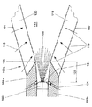
図1にはバーナの全体構造が示されている。以下に、始端部で作動する旋回流発生器100aの構成を図1および図2〜図5につき詳しく説明する。この旋回流発生器100aは円錐状の形成体であり、この形成体には、接線方向に流入する燃焼空気流115が接線方向で数回供給される。このときに形成される流れは、旋回流発生器100aの下流側に設定された移行ジオメトリに基づき、シームレスに移行部分200に引き渡され、この場合、この場所に剥離領域は生じ得ない。このような移行ジオメトリの配置構成は図6につき詳しく説明する。この移行部分200は移行ジオメトリの流出側で管20によって延長されており、この場合、両構成部分はバーナの固有の混合管220(混合区間とも呼ぶ)を形成している。当然ながら、この混合管220は唯一つの部分から成っていてもよい。すなわち、移行部分200と管20とが溶着されて、唯一つのまとまった形成体を形成していてもよく、ただしこの場合、各構成部分の特性は維持される。移行部分200と管20とが2つの構成部分から形成される場合には、移行部分200と管20とがブシュリング10によって結合されており、この場合、同じブシュリング10がヘッド側では旋回流発生器100aのための固定面として働く。このようなブシュリング10はさらに、種々異なる混合管を使用することができるという利点を有している。管20の流出側では、固有の燃焼器30が設けられている。この燃焼器30はこの場合、単に火炎管によって象徴的に図示されている。混合管220は、旋回流発生器100aの下流側で、種々異なる種類の燃焼の完全な予混合が得られるような、規定された混合区間を提供するという条件を満たしている。この混合区間、つまり混合管220は、さらに損失なしの流れ案内を可能にするので、移行ジオメトリと作用結合された状態においても、さしあたり逆流域は形成され得ない。これによって、混合管220の長さにわたってあらゆる種類の燃料のための混合品質に影響を与えることができる。しかし、この混合管220はさらに別の特性を有している。この特性とは、混合管220内で軸方向速度分布も軸線上で顕著な最大値を有するので、燃焼器からの火炎の逆火が不可能となることにある。もちろん、このような配置構成においてこの軸方向速度が壁に向かって減少することは事実である。この範囲においても逆火を阻止するためには、混合管220に流れ方向および周方向において、規則的または不規則的に分配された、種々異なる横断面および方向を有する多数の孔21が設けられる。これらの孔21を通じて、混合管220の内部に空気量が流入し、この空気量は壁に沿って、膜を形成するように速度の増大を生ぜしめる。同じ作用を得るための別の手段は、混合管220の流過横断面が、既に述べた移行ジオメトリを形成する移行通路201の流出側で狭隘を受けることにある。これにより、混合管220内部での速度レベル全体が高められる。図面では、前記孔21がバーナ軸線60に対して鋭角の角度で延びている。さらに、移行通路201の出口は混合管220の最も狭い流過横断面に相当している。したがって、前記移行通路201は、形成された流れに不都合な影響を与えることなしに各横断面差を補償している。選択されたこのような手段が、混合管220に沿った管流40の案内時に、許容し得ない圧力損失を生ぜしめる場合には、混合管の端部にディフューザ(図示しない)を設けることにより、このような圧力損失を回避することができる。混合管220の端部には、燃焼器30が続いており、この場合、両流過横断面の間には飛躍的な横断面拡張部が存在している。この場所ではじめて中央の逆流域50が形成される。この逆流域50は保炎器の特性を有している。運転時にこの飛躍的な横断面拡張部内で流れ縁域が形成されて、この流れ縁域に生ぜしめられる負圧に基づき渦流剥離が生じると、このことは逆流域50の増幅されたリング安定化をもたらす。端面側において燃焼器30は多数の開口31を有している。これらの開口31を通じて飛躍的な横断面拡張部に直接に空気量が流入する。この空気量は特に、逆流域50のリング安定化を増幅するために役立つ。ただしこの場合、安定した逆流域50を形成するためには、管体内における十分に高いスワール数も必要となることが考慮されなければならない。このような高いスワール数がさしあたり望ましくない場合には、管端部で、たとえば接線方向の開口を通じて、著しい旋回流を付与された小さな空気流を供給することによって、安定した逆流域を形成することができる。ただしこの場合、この目的のために必要となる空気量が全空気量の約5〜20%であることを前提とする。混合管220の端部における剥離縁部(Abrisskante)の構成に関しては、図8につき詳しく説明する。
【0017】
図2には、旋回流発生器100aの概略図が示されている。以下に、この旋回流発生器100aをさらに図3〜図5につき詳しく説明する。図1にも示した、真ん中に配置された燃料ノズル103は、円錐状の流過横断面の始端部125に対して上流側に向かって後方へずらされており、この場合、区間126は設定された燃料噴霧体105の角度に関連している。このように燃料ノズル103が後方へずらされていることに基づき、燃料ノズル103の噴射開口104をヘッド側の固定の周壁である円筒状の始端部分101a,102a(あとで説明する)の範囲に位置させることができる。燃料ノズル103が後方へずれされていることに基づき生じる燃料噴霧体105は、比較的大きな円錐半径を描いて、バーナ内室として形成された円錐状中空室114に流入する燃焼空気の主流によってカバーされた範囲に流入するので、燃料噴霧体105はこの範囲では、もはやコンパクトな固い物体の特性を有するのではなく、既に液滴の形に崩壊しており、したがってこの燃料噴霧体105は容易に貫通可能となる。燃料噴霧体105への燃焼空気115の供給は、もはや妨げられることなく行われる。このことは、混合品質に好都合な影響を与え、この場合、燃料噴霧体105は燃焼空気によって一層容易に貫通されるようになる。さらに、燃料噴霧体の噴射開口104の平面の範囲では、半径方向またはほぼ半径方向に配置された開口124が設けられている。この開口124を通じて、燃料ノズル103の大きさによって規定される横断面に掃気空気(Spuelluft)が流入する。この開口124の流過横断面は、気体燃料運転時にこれらの開口を通って流れる空気質量流が、逆流域(図1参照)をさらに下流側にずらすためには不十分となるように設定される。液体燃料運転時においては、燃料噴霧体105が実際には噴流ポンプとして作用する。これによって、前記開口124を通る空気質量流は増大する。このことは比較的大きな軸方向脈動を生ぜしめ、この軸方向脈動は逆流域をさらに下流側に移動させる。このことは火炎の逆火を防止するための良好な手段として作用する。
【0018】
図2〜図5につき、図示の部分円錐体101,102に関して詳しく説明する。この場合、接線方向の空気流入スリット119,120の配置構成および作用形式に関しても詳しく説明する。
【0019】
旋回流発生器100aの構造を良好に理解するためには、図2と同時に少なくとも図3を参照することが好ましい。さらに、図2を不必要に見難くしないようにするために、図2には、図3に概略的に示したガイド薄板121a,121bが象徴的にしか図示されていない。以下において、図2につき説明を行う(必要に応じて別の図面も参照)。
【0020】
図1に示したバーナの第1の部分は、図2に示した旋回流発生器100aを形成している。この旋回流発生器100aは中空の2つの部分円錐体101,102から成っている。両部分円錐体は互いにずらされてかつ互いに内外に入り組まれている。部分円錐体の数はもちろん、図4および図5に示したように2つよりも多くてもよい。このことは、それぞれ(さらに下で詳しく説明するように)バーナ全体の運転形式に関連している。特定の運転条件においては、唯一つの螺旋体から成る旋回流発生器を設けることも排除されていない。両部分円錐体101,102の各中心軸線または長手方向対称軸線101b,102bが互いにずらされていることに基づき、互いに隣接した壁では鏡像対称的な配置形式でそれぞれ1つの接線方向の通路、つまり空気流入スリット119,120が形成されている(図3参照)。この空気流入スリット119,120を通じて、燃料空気115が旋回流発生器110aの内室に、つまり円錐状中空室114に流入する。流れ方向における、図示の部分円錐体101,102の円錐形状は、規定された固定角度を有している。当然ながら、運転形式に応じて部分円錐体101,102が流れ方向で見て、たとえばトランペット形もしくはチューリップ形のように増大する円錐傾斜または減少する円錐傾斜を有していてもよい。トランペット形やチューリップ形の形状は当業者にとって容易に実現可能であるので、図面には示していない。両部分円錐体101,102は各1つの円筒状の始端部分101a,102aを有しており、両始端部分はやはり部分円錐体101,102本体と同様に互いにずらされて延びているので、接線方向の空気流入スリット119,120は旋回流発生器100aの全長にわたって存在している。円筒状の始端部分の範囲には、有利には液体燃料112のための燃料ノズル103が収納されている。この燃料ノズル103の噴射開口104は、部分円錐体101,102によって形成された円錐状中空室114の最小横断面とほぼ合致している。この燃料ノズル103の噴射容量および形式は、各バーナの所定のパラメータに関連して選択されている。当然ながら、旋回流発生器100aは純円錐状に、つまり円筒状の始端部分101a,102aなしに形成されていてもよい。さらに両部分円錐体101,102は各1つの燃料管路108,109を有している。この燃料管路は接線方向の空気流入スリット119,120に沿って配置されていて、複数の噴射開口117を備えている。これらの噴射開口117を通じて、有利には気体燃料113が、この場所を通流する燃焼空気115に噴射される(矢印116参照)。この燃料管路108,109は遅くとも、接線方向の流入部の端部で、円錐状中空室114への入口の手前に配置されていると有利であり、これにより最適な空気・燃料混合物が得られる。燃料ノズル103によって供給される燃料112は既に述べたように、通常の場合では液体燃料である。この場合、別の媒体との混合物形成は容易に可能である。この液体燃料112は鋭角の角度で円錐状中空室114に噴射される。したがって燃料ノズル103からは、円錐状の燃料噴霧体105が形成され、この燃料噴霧体105は接線方向に流入する回転する燃焼空気115によって取り囲まれる。軸方向では、噴射された液体燃料112の濃度が、流入する燃焼空気115によって連続的に減じられて、蒸発方向での混合が行われる。噴射開口117を介して気体燃料113が導入されると、燃料・空気混合物の形成が直接に空気流入スリット119,120の端部で行われる。燃焼空気115が付加的に予熱されているか、またはたとえば再循環された煙道ガスまたは排ガスで濃厚にされていると、このことは、この混合物が、後置された段に流入する前に液体燃料112の蒸発を持続的に助成する。同様の思想は、燃料管路108,109を介して液体燃料を供給したい場合にも云える。部分円錐体101,102の構成において円錐頂角と、接線方向の空気流入スリット119,120の幅に関しては、旋回流発生器100aの出口において燃焼空気115の所望の流れ領域が生じるようにするために、それ自体狭い範囲が維持されなければならない。一般的には、接線方向の空気流入スリット119,120を減小させると、既に旋回流発生器の範囲において逆流域の形成が一層迅速に促進されることが云える。旋回流発生器100aの内部における軸方向速度は軸方向の燃焼空気流の対応する供給(図示しない)によって変化させることができる。相応する旋回流の発生に基づき、旋回流発生器100aに後置された混合管内部での流れ剥離の形成は阻止される。旋回流発生器100aの構造はさらに、接線方向の空気流入スリット119,120の大きさを変化させるために適しているので有利である。これにより、旋回流発生器100aの構成長さを変化させることなく比較的大きな運転帯域幅を得ることができる。当然ながら、部分円錐体101,102は別の平面においても互いに移動可能であり、これにより両部分円錐体をオーバラップさせることもできる。さらに、部分円錐体101,102を互いに逆向きに回転する運動によって螺旋状に互いに内外に入り組ませることも可能である。したがって、接線方向の空気流入スリット119,120の形状、大きさおよび配置構成を任意に変化させることが可能となり、これにより旋回流発生器100aはその構成長さの変化なしに多目的に使用可能となる。
【0021】
図4には、ガイド薄板121a,121bのジオメトリ配置構成が示されている。両ガイド薄板は流れ導入機能を有しており、この場合、両ガイド薄板はその長さに応じて、両部分円錐体101,102の各端部を燃焼空気115に対して上流方向で延長している。円錐状中空室114に通じた、燃焼空気115のための通路形成は、円錐状中空室114におけるこの通路の入口の範囲に配置された旋回支点123を中心にしてガイド薄板121a,121bを開閉させることによって最適化することができる。特にこのことは、接線方向の空気流入スリット119,120の最初のギャップ寸法を動的に変化させたい場合に必要となる。当然ながら、このような動的な手段を静的に行うこともできる。この場合、必要とされるガイド薄板は部分円錐体101,102と共に1つの固定構成部分を形成する。同じく、旋回流発生器100aをガイド薄板なしに運転することもできる。また、ガイド薄板に代わる別の補助手段を設けることもできる。
【0022】
図5に示した実施例は図4に示した実施例とは異なり、旋回流発生器100aが4つの部分円錐体130,131,132,133から形成されている。各部分円錐体に対する所属の長手方向対称軸線は130a,131a,132a,133aで示されている。このような配置構成に関しては、このような配置構成が、これによって生ぜしめられる比較的小さな旋回流強さに基づき、かつ対応して増大されたスリット幅との協働により、混合管中で旋回流発生器の流出側に渦流が崩壊することを阻止するために好適であることが云える。これによって、混合管は、この混合管に与えられた役目を良好に果たすことができる。
【0023】
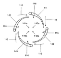
図6に示した実施例は、部分円錐体140,141,142,143が羽根形横断面を有している点で、図5に示した実施例とは異なっている。この羽根形横断面は特定の流れを発生させるために設けられる。旋回流発生器の運転形式はその他の点では前記実施例と同様である。燃焼空気流115への燃料(矢印116)の混加は羽根形横断面の内部から行われる。つまりこの場合、燃料管路108が個々の羽根に組み込まれている。この場合にも、個々の部分円錐体に対する長手方向対称軸線は140a,141a,142a,143aで示されている。
【0024】
図7には、移行部分200が三次元図面で示されている。この移行ジオメトリは図4または図5に示した実施例に対応して4つの部分円錐体を備えた旋回流発生器100aに合わせて形成されている。したがって、この移行ジオメトリは上流側で作用する部分円錐体の固有の延長部として4つの移行通路201を有している。これにより、前記部分円錐体の円錐4分面は、管20の壁もしくは混合管220の壁に交差するまで延長される。同様の思想は、旋回流発生器が図2につき説明した原理とは異なる別の原理に基づき形成されている場合にも云える。個々の移行通路201の、下方に向かって流れ方向に延びる面は、流れ方向で見て螺旋状に延びる形状を有している。この形状は、移行部分200の流過横断面がこの場合流れ方向で円錐状に拡張しているという事実に対応して、鎌形の軌道を描いている。流れ方向における移行通路201の旋回角度は、引き続き燃焼器入口における飛躍的な横断面拡大部にまで、噴霧された燃料との完全な予混合を実施するために十分に大きな区間がまだ管流に残るように設定されている。さらに、上記手段により、旋回流発生器の下流側における混合管壁での軸方向速度も増大する。このような移行ジオメトリおよび混合管の範囲における上記手段に基づき、混合管の中心点に向かって軸方向速度分布の著しい増大が行われるので、早期着火の危険も十分に回避される。
【0025】
図8には既に述べた、バーナ出口に形成された剥離縁部が示されている。管20の流過横断面には、この範囲において移行半径Rが付与される。この移行範囲Rの大きさは原則的に管20の内部の流れに関連して設定される。移行半径Rは、流れが壁に接触して、スワール数を著しく増大させるように設定される。移行半径Rの値は、この値が管20の内径dの>10%となるように規定される。このような曲率半径なしの流れに比べて、逆流域50の膨らみは著しく増大する。この移行半径Rは管20の出口平面にまで延びており、この場合、湾曲の始端部と終端部との間の角度βは<90゜となる。角度βを成す一方の辺に沿って、剥離縁部Aが管20の内部に向かって延びており、したがって剥離縁部Aの前方の点に対する剥離段Sが形成される。この剥離段Sの深さは>3mmである。当然ながら、この場合、管20の出口平面に対して平行に延びる剥離縁部を、湾曲させられた形状に沿って再び出口平面段にもたらすこともできる。剥離縁部Aの接線と、管20の出口平面に対する垂直線との間で広がる角度β‘は角度βと同じ大きさである。このような構成の利点は既に上で述べた通りである。
【図面の簡単な説明】
【図1】旋回流発生器の下流側の混合区間を有する、予混合バーナとして形成されたバーナの全体図である。
【図2】旋回流発生器の概略図である。
【図3】図1に示した予混合バーナの構成要素である旋回流発生器の斜視図である。
【図4】図3に示した旋回流発生器の断面図である。
【図5】4つの部分円錐体を備えた旋回流発生器の断面図である。
【図6】羽根形の部分円錐体を備えた旋回流発生器の断面図である。
【図7】旋回流発生器と混合区間との間の移行ジオメトリを示す斜視図である。
【図8】逆流域を三次元的に安定化するための剥離縁部を示す断面図である。
【符号の説明】
10 ブシュリング、 20 管、 21 孔、 30 燃焼器、 31 開口、 40 管流、 50 逆流域、 60 バーナ軸線、 100a 旋回流発生器、 101,102 部分円錐体、 101a,102a 始端部分、 101b,102b 長手方向対称軸線、 103 燃料ノズル、 104 噴射開口、 105 燃料噴霧体、 108,109 燃料管路、 112 液体燃料、 113 気体燃料、 114 円錐状中空室、 115 燃焼空気流、116 矢印、 117 噴射開口、 119,120 空気流入スリット、121a,121b ガイド薄板、 123 旋回支点、 124 開口、 125 始端部、 126 区間、 130,131,132,133 部分円錐体、 130a,131a,132a,133a 長手方向対称軸線、 140,141,142,143 部分円錐体、 140a,141a,142a,143a 長手方向対称軸線、 200 移行部分、 201 移行通路、 220 混合管、 d 管の内径、 R 移行半径、 T 接線、 A 剥離縁部、 S 剥離段、 β 角度[0001]
BACKGROUND OF THE INVENTION
The present invention is a burner used in a heat generator, and mainly comprises a swirl flow generator for a combustion air flow and a means for injecting and introducing fuel into the combustion air flow. About.
[0002]
[Prior art]
Such a swirl flow stabilizing burner is known as a premix burner based on, for example, EP 0 321 809. When liquid fuel is injected along the burner axis in such a burner, the liquid column formed on the downstream side by the fuel nozzle is compared with the combustion air flow flowing in the tangential direction into the inner chamber of the premixing burner. In particular, it acts like a solid in the first range downstream of the injection opening. Compared to the flow without liquid fuel injection, the combustion air supply in the burner head is hindered, so the tangential component of the swirling flow formed is amplified. This causes a change in the flame position, and in this case, the flame position moves further upstream. If further fuel injection is performed along the tangential air inlet slit, such fuel injection operation is at great risk. This is because it is inevitable that a flame surface acting on this area will cause backfire to the system. In addition, thickening of the flame center occurs, and such thickening causes various disadvantages to the operation of the premix burner. Various inconveniences can be recognized in such operation. These inconveniences include, for example (but not all):
[0003]
a) The risk of flashback is increased to a degree that cannot be ignored, in which case this can easily lead to the burning of the components of the premix burner. When such a burnout occurs, there is a risk that the collapsed component will cause serious damage to the machine.
[0004]
b) For safety reasons, the operation at the optimum flame position using liquid fuel should not be set widely. Accordingly, the premix burner has only a small operating area.
[0005]
c) For the above reasons, there is no intimate mixing between the conical spray and the combustion air flow, so a significant increase in Nox emissions is inevitable.
[0006]
d) In addition, another disadvantage arises due to the inhomogeneous mixture distribution resulting in an increased release of harmful substances and generation of pulsations.
[0007]
e) A large deviation is observed with respect to the optimum flow conditions for obtaining reliable and effective combustion.
[0008]
[Problems to be solved by the invention]
The object of the present invention is to improve a premixed burner of the type mentioned at the outset so that the efficiency is maximized, the release of harmful substances is minimized and the stabilization of the flame is obtained. Is to provide.
[0009]
[Means for Solving the Problems]
In order to solve this problem, in the configuration of the present invention, the mixing section is arranged on the downstream side of the swirling flow generator, and the mixing section has a transition passage extending in the flow direction inside the first section portion. And the transition passage serves to deliver the flow formed in the swirling flow generator into a pipe disposed downstream of the transition passage, and further for injecting and introducing fuel into the combustion air. The fuel nozzle worked as a means, and the fuel nozzle was shifted to the upstream side by a predetermined interval with respect to the starting end portion of the swirling flow generator.
[0010]
【The invention's effect】
A major feature of the present invention is that the position of the fuel nozzle on the head side is shifted upstream by a predetermined interval with respect to the inflow portion of the combustion air. This interval is related to the selected sprayer angle. Based on such a deviation, the injection opening of the fuel nozzle is located in the range of the fixed peripheral wall, and at the same time, an opening for scavenging air can be provided so as to surround the injection opening in the radial direction. . Through this opening, scavenging air flows into the cross section formed by the fuel nozzle. The flow cross section of the opening is set so that the gaseous mass of air flowing through the opening is insufficient for moving the backflow region further downstream with gaseous fuel. In liquid fuel operation, the fuel sprayer actually acts as a jet pump. Thereby, the air mass flow is enhanced by the opening. This creates a larger axial pulsation that moves the back flow region further downstream.
[0011]
Another advantage of the present invention is that the fuel sprayer flows into the mainstream with a larger cone radius, i.e. into the combustion air flowing through the tangential air inlet slit, due to the fuel nozzle being displaced. It is in. The fuel spray body has already collapsed in this plane from the membrane into droplets, and the conical outer surface of this fuel spray body increases by a factor of 3 when entering the range of combustion air from the tangential air inlet slit. ing. Thereby, the adjustment of the fuel spray body is improved and the inflow of combustion air is not hindered.
[0012]
Furthermore, the mass of air sucked through an opening provided in the area of the fuel nozzle prevents wetting of the internal tip of the cone. This is because the air mass flow enters as a film between the fuel spray body and the wall, and in particular defines the opening angle of the fuel spray body. This opening angle is kept constant over a large load area.
[0013]
Yet another significant advantage of the present invention is that by changing the open cross-section for air mass flow in the range of the fuel nozzle, it is possible to influence the back flow region and thus the flame position during operation. is there.
[0014]
Advantageous configurations of the invention are described in claims 2 and below.
[0015]
DETAILED DESCRIPTION OF THE INVENTION
In the following, embodiments of the present invention will be described in detail with reference to the drawings. All components that are not necessary for a direct understanding of the present invention are omitted. The same reference numerals are used for the same components in the various drawings. The direction of media flow is indicated by arrows.
[0016]
FIG. 1 shows the overall structure of the burner. Below, the structure of the swirl |
[0017]
FIG. 2 shows a schematic diagram of the
[0018]
2 to 5, the illustrated
[0019]
In order to better understand the structure of the swirling
[0020]
The first part of the burner shown in FIG. 1 forms the
[0021]
FIG. 4 shows a geometry arrangement configuration of the guide
[0022]
The embodiment shown in FIG. 5 differs from the embodiment shown in FIG. 4 in that the
[0023]
The embodiment shown in FIG. 6 differs from the embodiment shown in FIG. 5 in that the
[0024]
In FIG. 7, the
[0025]
FIG. 8 shows the already described peeling edge formed at the burner outlet. A transition radius R is given to the flow cross section of the
[Brief description of the drawings]
FIG. 1 is an overall view of a burner formed as a premixing burner with a mixing section downstream of a swirl flow generator.
FIG. 2 is a schematic view of a swirling flow generator.
FIG. 3 is a perspective view of a swirling flow generator that is a component of the premixing burner shown in FIG. 1;
4 is a cross-sectional view of the swirling flow generator shown in FIG. 3. FIG.
FIG. 5 is a cross-sectional view of a swirl flow generator with four partial cones.
FIG. 6 is a cross-sectional view of a swirl flow generator with vane-shaped partial cones.
FIG. 7 is a perspective view showing the transition geometry between the swirl generator and the mixing section.
FIG. 8 is a cross-sectional view showing a separation edge for stabilizing a backflow region three-dimensionally.
[Explanation of symbols]
10 Bushlings, 20 tubes, 21 holes, 30 combustors, 31 openings, 40 tube flows, 50 reverse flow regions, 60 burner axes, 100a swirl flow generators, 101, 102 partial cones, 101a, 102a start end portions, 101b, 102b longitudinal symmetry axis, 103 fuel nozzle, 104 injection opening, 105 fuel spray, 108, 109 fuel line, 112 liquid fuel, 113 gas fuel, 114 conical hollow chamber, 115 combustion air flow, 116 arrow, 117 injection Opening, 119, 120 Air inflow slit, 121a, 121b Guide thin plate, 123 Rotating fulcrum, 124 Opening, 125 Start end, 126 Section, 130, 131, 132, 133 Partial cone, 130a, 131a, 132a, 133a Longitudinal symmetry Axis, 140, 141, 142, 143 parts Cone, 140a, 141a, 142a, 143a longitudinal axis of symmetry, 200 transition portion, 201 transfer passages, 220 mixing tube, the inside diameter of the d line, R transition radius, T tangent, A peeling edge, S stripping stage, beta angle
Claims (17)
Applications Claiming Priority (2)
| Application Number | Priority Date | Filing Date | Title |
|---|---|---|---|
| DE19547912A DE19547912A1 (en) | 1995-12-21 | 1995-12-21 | Burners for a heat generator |
| DE19547912.2 | 1995-12-21 |
Publications (2)
| Publication Number | Publication Date |
|---|---|
| JPH09178121A JPH09178121A (en) | 1997-07-11 |
| JP3904644B2 true JP3904644B2 (en) | 2007-04-11 |
Family
ID=7780867
Family Applications (1)
| Application Number | Title | Priority Date | Filing Date |
|---|---|---|---|
| JP33972796A Expired - Lifetime JP3904644B2 (en) | 1995-12-21 | 1996-12-19 | Burner used for heat generator |
Country Status (5)
| Country | Link |
|---|---|
| US (1) | US5876196A (en) |
| EP (1) | EP0780630B1 (en) |
| JP (1) | JP3904644B2 (en) |
| CN (1) | CN1111672C (en) |
| DE (2) | DE19547912A1 (en) |
Cited By (1)
| Publication number | Priority date | Publication date | Assignee | Title |
|---|---|---|---|---|
| JP2013002706A (en) * | 2011-06-15 | 2013-01-07 | Chugai Ro Co Ltd | Combustion device |
Families Citing this family (25)
| Publication number | Priority date | Publication date | Assignee | Title |
|---|---|---|---|---|
| DE19639301A1 (en) * | 1996-09-25 | 1998-03-26 | Abb Research Ltd | Burner for operating a combustion chamber |
| DE19640198A1 (en) * | 1996-09-30 | 1998-04-02 | Abb Research Ltd | Premix burner |
| DE19736902A1 (en) * | 1997-08-25 | 1999-03-04 | Abb Research Ltd | Burners for a heat generator |
| DE59709791D1 (en) * | 1997-09-19 | 2003-05-15 | Alstom Switzerland Ltd | Burner for operating a heat generator |
| EP0909921B1 (en) * | 1997-10-14 | 2003-01-02 | Alstom | Burner for operating a heat generator |
| EP0913630B1 (en) * | 1997-10-31 | 2003-03-05 | ALSTOM (Switzerland) Ltd | Burner for the operation of a heat generator |
| EP0916894B1 (en) * | 1997-11-13 | 2003-09-24 | ALSTOM (Switzerland) Ltd | Burner for operating a heat generator |
| DE10051221A1 (en) * | 2000-10-16 | 2002-07-11 | Alstom Switzerland Ltd | Burner with staged fuel injection |
| JP4524902B2 (en) * | 2000-10-25 | 2010-08-18 | 株式会社Ihi | Low NOx combustor with premixed fuel injection valve |
| EP1217295B1 (en) * | 2000-12-23 | 2006-08-23 | ALSTOM Technology Ltd | Burner for generating a hot gas |
| EP1255077B1 (en) * | 2001-04-30 | 2008-06-11 | ALSTOM Technology Ltd | Device for the combustion of a gaseous mixture of fuel and oxidant |
| EP1262714A1 (en) | 2001-06-01 | 2002-12-04 | ALSTOM (Switzerland) Ltd | Burner with exhausts recirculation |
| CN1942710A (en) * | 2004-02-12 | 2007-04-04 | 阿尔斯通技术有限公司 | Premixing and burner arrangement for operating a combustor and method of operating a combustor |
| US7097448B2 (en) * | 2004-05-07 | 2006-08-29 | Peter Chesney | Vortex type gas lamp |
| WO2006058843A1 (en) * | 2004-11-30 | 2006-06-08 | Alstom Technology Ltd | Method and device for burning hydrogen in a premix burner |
| JP4977522B2 (en) * | 2007-04-25 | 2012-07-18 | 株式会社日立製作所 | Gas turbine combustor |
| DE102008000050A1 (en) * | 2007-08-07 | 2009-02-12 | Alstom Technology Ltd. | Burner for a combustion chamber of a turbo group |
| GB0902221D0 (en) * | 2009-02-11 | 2009-03-25 | Edwards Ltd | Pilot |
| USD621873S1 (en) | 2009-07-09 | 2010-08-17 | Science Centre Board | Fire tornado lamp |
| US9170017B2 (en) | 2010-01-06 | 2015-10-27 | The Outdoor Greatroom Company LLLP | Fire container assembly |
| FR3011911B1 (en) | 2013-10-14 | 2015-11-20 | Cogebio | BURNER OF POOR GAS |
| DE102014205198A1 (en) * | 2014-03-20 | 2015-09-24 | Kba-Metalprint Gmbh | Burner and device for thermal afterburning of exhaust air |
| DE102014205200B3 (en) * | 2014-03-20 | 2015-06-11 | Kba-Metalprint Gmbh | Device for thermal afterburning of exhaust air |
| CN108006695B (en) * | 2016-11-01 | 2019-12-06 | 北京华清燃气轮机与煤气化联合循环工程技术有限公司 | Method of optimizing a premix fuel nozzle for a gas turbine |
| DE102021001584B4 (en) * | 2021-03-25 | 2024-03-07 | Mercedes-Benz Group AG | Burner for a motor vehicle |
Family Cites Families (15)
| Publication number | Priority date | Publication date | Assignee | Title |
|---|---|---|---|---|
| CH392746A (en) * | 1962-01-12 | 1965-05-31 | Elco Oelbrennerwerk Ag | Burner head |
| US3656692A (en) * | 1971-01-05 | 1972-04-18 | Texaco Inc | Oil burner |
| US3851466A (en) * | 1973-04-12 | 1974-12-03 | Gen Motors Corp | Combustion apparatus |
| US3905192A (en) * | 1974-08-29 | 1975-09-16 | United Aircraft Corp | Combustor having staged premixing tubes |
| US4014639A (en) * | 1975-04-10 | 1977-03-29 | Minnesota Mining And Manufacturing Company | Recirculating vortex burner |
| US4271675A (en) * | 1977-10-21 | 1981-06-09 | Rolls-Royce Limited | Combustion apparatus for gas turbine engines |
| US4561841A (en) * | 1980-11-21 | 1985-12-31 | Donald Korenyi | Combustion apparatus |
| GB2175684B (en) * | 1985-04-26 | 1989-12-28 | Nippon Kokan Kk | Burner |
| CH674561A5 (en) | 1987-12-21 | 1990-06-15 | Bbc Brown Boveri & Cie | |
| CH680157A5 (en) * | 1989-12-01 | 1992-06-30 | Asea Brown Boveri | |
| JPH07190308A (en) * | 1993-12-28 | 1995-07-28 | Hitachi Ltd | Swivel burner |
| DE4408136A1 (en) * | 1994-03-10 | 1995-09-14 | Bmw Rolls Royce Gmbh | Method for fuel preparation for gas turbine combustion chamber |
| FR2717250B1 (en) * | 1994-03-10 | 1996-04-12 | Snecma | Premix injection system. |
| DE4416650A1 (en) * | 1994-05-11 | 1995-11-16 | Abb Management Ag | Combustion process for atmospheric combustion plants |
| DE4435266A1 (en) * | 1994-10-01 | 1996-04-04 | Abb Management Ag | burner |
-
1995
- 1995-12-21 DE DE19547912A patent/DE19547912A1/en not_active Withdrawn
-
1996
- 1996-11-27 EP EP96810827A patent/EP0780630B1/en not_active Expired - Lifetime
- 1996-11-27 DE DE59607769T patent/DE59607769D1/en not_active Expired - Lifetime
- 1996-12-04 US US08/760,410 patent/US5876196A/en not_active Expired - Lifetime
- 1996-12-19 JP JP33972796A patent/JP3904644B2/en not_active Expired - Lifetime
- 1996-12-21 CN CN96123843A patent/CN1111672C/en not_active Expired - Lifetime
Cited By (1)
| Publication number | Priority date | Publication date | Assignee | Title |
|---|---|---|---|---|
| JP2013002706A (en) * | 2011-06-15 | 2013-01-07 | Chugai Ro Co Ltd | Combustion device |
Also Published As
| Publication number | Publication date |
|---|---|
| DE59607769D1 (en) | 2001-10-31 |
| CN1111672C (en) | 2003-06-18 |
| EP0780630A3 (en) | 1998-07-29 |
| US5876196A (en) | 1999-03-02 |
| JPH09178121A (en) | 1997-07-11 |
| EP0780630A2 (en) | 1997-06-25 |
| DE19547912A1 (en) | 1997-06-26 |
| CN1157893A (en) | 1997-08-27 |
| EP0780630B1 (en) | 2001-09-26 |
Similar Documents
| Publication | Publication Date | Title |
|---|---|---|
| JP3904644B2 (en) | Burner used for heat generator | |
| JP3904685B2 (en) | Premix burner | |
| CN1090728C (en) | Burner | |
| JP4130716B2 (en) | Burner for operating the heat generator | |
| US5735687A (en) | Burner for a heat generator | |
| JP4442940B2 (en) | Burner for heat generator | |
| US6019596A (en) | Burner for operating a heat generator | |
| JP3011775B2 (en) | Burners and burner operating methods | |
| JP5399462B2 (en) | Method for operating the burner device | |
| JP3828969B2 (en) | Premix burner | |
| JP3904655B2 (en) | Burner for heat generator | |
| JP4263278B2 (en) | Burner for operating the heat generator | |
| US6152726A (en) | Burner for operating a heat generator | |
| JP4001952B2 (en) | Combustion chamber | |
| US5954495A (en) | Burner for operating a heat generator | |
| JP4155635B2 (en) | Burner for operating the heat generator | |
| JP3889079B2 (en) | Burner | |
| JPH08189611A (en) | Burner | |
| US5954490A (en) | Burner for operating a heat generator | |
| JP3904684B2 (en) | Burner for operating the combustion chamber | |
| US6059565A (en) | Burner for operating a heat generator | |
| JP3842357B2 (en) | Premix burner for heat generator | |
| US5954496A (en) | Burner for operating a combustion chamber | |
| JPH1182941A (en) | Oxygen burner | |
| JPH09189405A (en) | Pre-mixing burner |
Legal Events
| Date | Code | Title | Description |
|---|---|---|---|
| A621 | Written request for application examination |
Free format text: JAPANESE INTERMEDIATE CODE: A621 Effective date: 20031209 |
|
| A131 | Notification of reasons for refusal |
Free format text: JAPANESE INTERMEDIATE CODE: A131 Effective date: 20060517 |
|
| A601 | Written request for extension of time |
Free format text: JAPANESE INTERMEDIATE CODE: A601 Effective date: 20060814 |
|
| A602 | Written permission of extension of time |
Free format text: JAPANESE INTERMEDIATE CODE: A602 Effective date: 20060817 |
|
| A521 | Request for written amendment filed |
Free format text: JAPANESE INTERMEDIATE CODE: A523 Effective date: 20061115 |
|
| TRDD | Decision of grant or rejection written | ||
| A01 | Written decision to grant a patent or to grant a registration (utility model) |
Free format text: JAPANESE INTERMEDIATE CODE: A01 Effective date: 20061215 |
|
| A61 | First payment of annual fees (during grant procedure) |
Free format text: JAPANESE INTERMEDIATE CODE: A61 Effective date: 20070110 |
|
| R150 | Certificate of patent or registration of utility model |
Free format text: JAPANESE INTERMEDIATE CODE: R150 |
|
| FPAY | Renewal fee payment (event date is renewal date of database) |
Free format text: PAYMENT UNTIL: 20110119 Year of fee payment: 4 |
|
| FPAY | Renewal fee payment (event date is renewal date of database) |
Free format text: PAYMENT UNTIL: 20110119 Year of fee payment: 4 |
|
| FPAY | Renewal fee payment (event date is renewal date of database) |
Free format text: PAYMENT UNTIL: 20120119 Year of fee payment: 5 |
|
| FPAY | Renewal fee payment (event date is renewal date of database) |
Free format text: PAYMENT UNTIL: 20130119 Year of fee payment: 6 |
|
| S111 | Request for change of ownership or part of ownership |
Free format text: JAPANESE INTERMEDIATE CODE: R313113 |
|
| FPAY | Renewal fee payment (event date is renewal date of database) |
Free format text: PAYMENT UNTIL: 20130119 Year of fee payment: 6 |
|
| R350 | Written notification of registration of transfer |
Free format text: JAPANESE INTERMEDIATE CODE: R350 |
|
| FPAY | Renewal fee payment (event date is renewal date of database) |
Free format text: PAYMENT UNTIL: 20140119 Year of fee payment: 7 |
|
| R250 | Receipt of annual fees |
Free format text: JAPANESE INTERMEDIATE CODE: R250 |
|
| R250 | Receipt of annual fees |
Free format text: JAPANESE INTERMEDIATE CODE: R250 |
|
| R250 | Receipt of annual fees |
Free format text: JAPANESE INTERMEDIATE CODE: R250 |
|
| S533 | Written request for registration of change of name |
Free format text: JAPANESE INTERMEDIATE CODE: R313533 |
|
| R350 | Written notification of registration of transfer |
Free format text: JAPANESE INTERMEDIATE CODE: R350 |
|
| EXPY | Cancellation because of completion of term |