JP3902402B2 - Automatic cash transaction equipment - Google Patents
Automatic cash transaction equipment Download PDFInfo
- Publication number
- JP3902402B2 JP3902402B2 JP2000393095A JP2000393095A JP3902402B2 JP 3902402 B2 JP3902402 B2 JP 3902402B2 JP 2000393095 A JP2000393095 A JP 2000393095A JP 2000393095 A JP2000393095 A JP 2000393095A JP 3902402 B2 JP3902402 B2 JP 3902402B2
- Authority
- JP
- Japan
- Prior art keywords
- information
- deposit
- cassette
- control unit
- banknote
- Prior art date
- Legal status (The legal status is an assumption and is not a legal conclusion. Google has not performed a legal analysis and makes no representation as to the accuracy of the status listed.)
- Expired - Fee Related
Links
Images


Classifications
-
- G—PHYSICS
- G07—CHECKING-DEVICES
- G07F—COIN-FREED OR LIKE APPARATUS
- G07F19/00—Complete banking systems; Coded card-freed arrangements adapted for dispensing or receiving monies or the like and posting such transactions to existing accounts, e.g. automatic teller machines
- G07F19/20—Automatic teller machines [ATMs]
- G07F19/202—Depositing operations within ATMs
-
- G—PHYSICS
- G07—CHECKING-DEVICES
- G07F—COIN-FREED OR LIKE APPARATUS
- G07F19/00—Complete banking systems; Coded card-freed arrangements adapted for dispensing or receiving monies or the like and posting such transactions to existing accounts, e.g. automatic teller machines
-
- G—PHYSICS
- G06—COMPUTING; CALCULATING OR COUNTING
- G06Q—INFORMATION AND COMMUNICATION TECHNOLOGY [ICT] SPECIALLY ADAPTED FOR ADMINISTRATIVE, COMMERCIAL, FINANCIAL, MANAGERIAL OR SUPERVISORY PURPOSES; SYSTEMS OR METHODS SPECIALLY ADAPTED FOR ADMINISTRATIVE, COMMERCIAL, FINANCIAL, MANAGERIAL OR SUPERVISORY PURPOSES, NOT OTHERWISE PROVIDED FOR
- G06Q20/00—Payment architectures, schemes or protocols
- G06Q20/08—Payment architectures
- G06Q20/10—Payment architectures specially adapted for electronic funds transfer [EFT] systems; specially adapted for home banking systems
- G06Q20/108—Remote banking, e.g. home banking
- G06Q20/1085—Remote banking, e.g. home banking involving automatic teller machines [ATMs]
-
- G—PHYSICS
- G07—CHECKING-DEVICES
- G07D—HANDLING OF COINS OR VALUABLE PAPERS, e.g. TESTING, SORTING BY DENOMINATIONS, COUNTING, DISPENSING, CHANGING OR DEPOSITING
- G07D11/00—Devices accepting coins; Devices accepting, dispensing, sorting or counting valuable papers
- G07D11/20—Controlling or monitoring the operation of devices; Data handling
- G07D11/26—Servicing, repairing or coping with irregularities, e.g. power failure or vandalism
-
- G—PHYSICS
- G07—CHECKING-DEVICES
- G07D—HANDLING OF COINS OR VALUABLE PAPERS, e.g. TESTING, SORTING BY DENOMINATIONS, COUNTING, DISPENSING, CHANGING OR DEPOSITING
- G07D11/00—Devices accepting coins; Devices accepting, dispensing, sorting or counting valuable papers
- G07D11/20—Controlling or monitoring the operation of devices; Data handling
- G07D11/32—Record keeping
-
- G—PHYSICS
- G07—CHECKING-DEVICES
- G07F—COIN-FREED OR LIKE APPARATUS
- G07F19/00—Complete banking systems; Coded card-freed arrangements adapted for dispensing or receiving monies or the like and posting such transactions to existing accounts, e.g. automatic teller machines
- G07F19/20—Automatic teller machines [ATMs]
- G07F19/203—Dispensing operations within ATMs
Description
【0001】
【発明の属する技術分野】
本発明は、貨幣(紙幣および硬貨)を取り扱う現金自動取引装置に係り、特に、複数の異なる国で使用可能な現金自動取引装置に関する。なお、本発明は紙幣および硬貨を含む貨幣一般に適用できるが、以下では説明を簡単にするために”紙幣”を例にして説明する。
【0002】
【従来の技術】
金融機関などで使用される現金自動取引装置、特に日本国内で使用される現金自動取引装置においては、利用客へ紙幣を出金する出金取引と利用客が投入した紙幣を入金する入金取引をサポートするものが一般的である。
【0003】
例えば、紙幣を例に取ると、出金取引においては利用客から指定された枚数の紙幣を装置に搭載される紙幣入出金機構に内蔵される紙幣貯留部より繰出し、紙幣判別部で判別し、正しく判別された紙幣を出金口へ搬送し利用客へ放出し、また、入金取引においては利用客より紙幣入出金機構に投入された紙幣を、一枚ずつ繰出して搬送し、紙幣判別部で判別し、判別結果に従い入金された金額を表示し、利用客が確認し、入金金額を確定した上で入金取引を成立させるようにしている。
【0004】
しかし、海外などで使用される現金自動取引装置では、入金機能を有する現金自動取引装置はほとんど使用されておらず、出金機能のみを有するものがほとんどである。出金機能のみを有する現金自動取引装置の場合、紙幣入出金機構には紙幣を判別する機能は必須ではなく、予めセットされている金種が判かっているカセットから利用客より指定された金額の紙幣を必要枚数だけ繰り出して入出金口に搬送するだけでよい。
【0005】
このような装置としては、例えば特開平2−75551号公報に開示されたものがある。これは、紙幣を利用客へ放出するための入出金口と、金種別に紙幣を収納しておく複数の紙幣カセットと、リジェクト紙幣を収納するリジェクトカセットと、それらをつなぐ搬送路とから構成され、カセットから繰出した紙幣をそのまま入出金口へ搬送し、出金する方式となっている。
【0006】
このような方式の紙幣入出金機構においては、基本的に紙幣を判別する機能はなく、出金される紙幣の金種はセットされる紙幣の金種に左右されるため、カセットが誤った位置に入れられないように誤挿入防止機能(例えば、切り欠き部などを設ける)を持たせ、決った金種のカセットは決った位置にしか入らないようにしているか、セットされる金種情報をカセット自体に持たせておき、その金種情報によりセットされている金種を確認した上で、どのカセットから繰出すかを決めているものもある。
【0007】
また、使用される地域や国が異なり取り扱う紙幣が異なる場合には、カセットにセットする紙幣を地域や国に合せて変更すればよく、また取り扱う紙幣が異なる場合には、現金自動取引装置は、現金の集計処理などが異なるため、予めどこの国または地域の紙幣を取り扱うかの情報を保持しておきその情報を用いて運用する必要がある。
【0008】
【発明が解決しようとする課題】
上記のような海外などで使用される出金機能を主要目的とした現金自動取引装置において、さらに入金された紙幣を判別し計数する入金機能を有するものを実現しようとする場合、上記出金機能のみの場合と同様に予めどこの国または地域の紙幣を取り扱うかを決めて運用することになる。これは、一般的には世界中の紙幣を同時に取り扱うことは通常考えられず、ある特定の地域(国や共通通貨圏)に限定された紙幣を取り扱えるようにすれば十分であるからである。
【0009】
また、紙幣を判別し計数する入金機能を実現するためには、現金自動取引装置に搭載される紙幣入出金機構には紙幣判別機能が必須となる。しかし、紙幣を判別する機能においても、世界中の全ての紙幣を同時に見分け判別することは通常不可能であるが、ある特定の地域(国や共通通貨圏)に限定された紙幣についてその判別を行うことは可能であり、一般的にはそれで十分である。
【0010】
このように考えると、紙幣を判別する機能を有する現金自動取引装置においては、現金自動取引装置本体(本体制御部)と紙幣入出金機構とが取り扱う紙幣範囲を予め一致させておく必要がある。しかしながら、従来の国内で使用されているような現金自動取引装置では、基本的に、取り扱う紙幣は日本国内の紙幣に限定され、装置側も紙幣入出金機構も国内専用として作られているため、上記のような取り扱う紙幣の範囲(国、地域、共通通貨圏)に関する情報をやり取りする概念はなく、プログラム自体も国内専用として作成されており、上記のように紙幣を取り扱う紙幣の範囲に関する情報を保持していなかった。
【0011】
現金自動取引装置本体(本体制御部)が取り扱う紙幣範囲と紙幣入出金機構で判別可能な紙幣範囲を一致させておかなければ、取り扱う紙幣が全てリジェクトされたり、判別した紙幣を別の国の紙幣として集計したり、といった重大な障害を発生させる可能性があるので、複数の地域で異なった紙幣を取り扱うことを前提とした紙幣を判別する機能を有する現金自動取引装置においては、現金自動取引装置本体(本体制御部)が取り扱う紙幣範囲と紙幣入出金機構が判別可能な紙幣とを一致させておく必要がある。
【0012】
本発明は、上記問題点を解消し、紙幣を判別する機能を有する現金自動取引装置において、現金自動取引装置(本体制御部)が取り扱おうとする紙幣範囲と紙幣入出金機構(紙幣判別部)が取り扱える紙幣範囲(さらには紙幣収納庫(カセット)の紙幣の種別)を一致させて運用させることが可能な現金自動取引装置を提供することを目的とする。
【0013】
【課題を解決しようとする手段】
海外などにおいて複数の地域の紙幣を、設定を変更して取り扱える現金自動取引装置を実現するためには、その現金自動取引装置が取り扱おうとする紙幣の範囲を示す情報を装置(本体制御部)側に設定可能とするとともに、紙幣入出金機構には紙幣判別部で判別できる紙幣範囲を示す情報を付加し、運用開始時に装置が取り扱おうとする紙幣範囲の情報と紙幣入出金機構が有する判別範囲情報を、装置が運用に入るまでにチェックする。
【0014】
チェックの結果、不一致となった場合には運用に入らず、カセットを取りかえるか、装置が取り扱う紙幣範囲を変更するか、もしくは紙幣入出金機構の紙幣判別部を変更するなどにより紙幣判別可能範囲を変更する。これにより現金自動取引装置とそれに搭載される紙幣入出金機構の紙幣取り扱い範囲を合わせて装置として問題なく運用させることが可能となる。なお、特許請求の範囲における「貨幣取り扱い機構」は、実施例の紙幣入出金機構に相当している。
【0015】
【発明の実施の形態】
(概要)
複数の異なる国、地域の紙幣を紙幣判別し取り扱う現金自動取引装置において、装置が取り扱おうとする紙幣の範囲と紙幣入出金機構(紙幣判別部)が取り扱える紙幣の範囲を一致させなければ、リジェクト多発、集計異常などの不具合が発生するため、運用に入る前に装置(本体制御部)が取り扱おうとする紙幣の範囲と紙幣入出金機構(紙幣判別部)が取り扱える紙幣の範囲を一致させる必要がある。
【0016】
そのために、本発明では、現金自動取引装置本体(本体制御部)に取り扱う紙幣の範囲を示す情報を持たせるとともに、紙幣入出金機構に紙幣判別部で判別できる範囲を示す情報を持たせ、それらを現金自動取引装置本体(本体制御部)と紙幣入出金機構とで共有できるようにして、運用時にそれらをチェックして運用可能かどうかを判断して、運用可能の場合に運用に入り、運用不可能な場合は設定などを変更して運用可能とした後に運用に入るようにした。
【0017】
(実施例)
以下、本発明に係る現金自動取引装置の一実施例を、図面を参照して詳細に説明する。
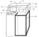
図1は、本発明を適用した現金自動取引装置1の外観を示す斜視図である。
同図に示すように、現金自動取引装置1の左部内部には、上部正面板11aに設けられたカード用のスロット14aと連通し、利用者のカードを処理し、取引明細票を印字して放出するカード・明細票処理機構14と、取引の内容を表示したり入力したりする顧客操作部13を備えている。
【0018】
また、現金自動取引装置1の右部内部には、紙幣を処理する紙幣入出金機構10を備えており、上部の傾いた上部正面板11aには紙幣投入や取出し用のスロット12が設けられている。また、紙幣入出金機構10の下部の紙幣収納部は、現金自動取引装置1全体を囲う装置筐体11bとは別の厚い鉄板で構成する金庫筐体15で囲まれている。装置筐体11b自体も堅固な構造であるが、金庫筐体15は防犯のためにさらに堅固な構造となっている。この現金自動取引装置1は、カード,紙幣,明細票などを媒体とし、利用者の預入れ,支払,振込などの処理を行うことができる。
【0019】
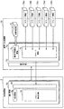
図2は、本装置の制御関係を示す制御ブロック図である。
前述のように現金自動取引装置1に納められた紙幣入出金機構10およびカード・明細票処理機構14は、それぞれ回線20aおよび20bを介して本体制御部2と接続され、また、顧客操作部13は、バス21aを介して本体制御部2と接続され、本体制御部2の制御下でそれぞれ必要な動作を行う。
【0020】
本体制御部2は、上記機構部や構成部分の他に、インタフェース部22,係員操作部23,外部記憶装置24ともバス21b,21c,21dを介して接続されており、必要なデータのやりとりを行う。なお、図2に示されている25は、上記各機構部や構成部分に電力を供給する電源部である。
【0021】
図3は、図1の現金自動取引装置1の中で、紙幣入出金機構10の制御関係を示す制御ブロック図である。
同図において、紙幣入出金機構10の制御部3は、現金自動取引装置1の本体制御部2と回線20aを介して接続され、本体制御部2からの指令または紙幣入出金機構10の状態検出に応じて紙幣入出金機構10の制御を行う。
【0022】
また、制御部3は、紙幣入出金機構10の動作状況を、必要に応じて本体制御部2に送る。紙幣入出金機構10の中では、各ユニット(入出金口30、紙幣判別部31、一時保管庫32、紙幣搬送路33、入金庫34、出金庫35、リサイクル庫36)の駆動モータや電磁ソレノイドやセンサ(図示せず)と接続され、各種取引に応じて、センサで状態を監視しながら、アクチュエータを駆動制御する。
【0023】
図4は、紙幣入出金機構10の機構部の構成を示す側面図である。
同図に示すように、紙幣入出金機構10は、主に、利用者が紙葉類の投入・取出しを行う入出金口30と、紙幣の判別を行う紙幣判別部31と、入金した紙幣を取引成立までの間一旦収納する一時保管庫32と、脱着可能な紙幣カセット34a〜34eと、紙幣判別部31を通りこれら紙幣カセットに対し紙幣を搬送する紙幣搬送路33(33a〜33c)と、制御部3とから構成される。なお、図4では制御部3は省略されている(図3参照)。
【0024】
例えば、同図において、紙幣カセット34aを入金時取引が成立した紙幣を収納する入金庫(図3の34に相当)とし、紙幣カセット34b〜34dを入出金兼用の3個のリサイクル庫(図3の36に相当)とし、紙幣カセット34eを出金用の紙幣を収納する出金庫(図3の35に相当)とする構成が考えられる。これら紙幣カセットの構成は変更可能であり、例えば最下段の出金庫34eをリサイクル庫にすることも可能である。
【0025】
図4において、紙幣入出金機構10は、入出金口30,紙幣判別部31,一時保管庫32,および紙幣搬送路33aから構成される上部搬送機構10aと、入金庫34a,リサイクル庫34b〜34d,出金庫34e,および各収納庫の前面に配される開閉可能な搬送路40から構成される下部紙幣機構10bとから構成される。
【0026】
さらに、下部紙幣機構10bは、厚い鉄板(この例では約50mmの厚さ)で構成される金庫筐体15の中に実装されており、上部搬送機構10aと下部紙幣機構10bとの搬送路は、連結搬送路33bによって相互に接続されている。
【0027】
なお、下部紙幣機構10bを金庫筐体で囲わない構成を採用することも可能である。この場合は下部紙幣機構10b上に直接上部搬送機構10aを載置する。
【0028】
また、紙幣搬送路33(33a〜33c)は、紙幣判別部31を双方向に通過させるとともに、入出金口30,一時保管庫32,入金庫34a,リサイクル庫34b〜34d,および出金庫34eの間を相互に接続し、取引動作毎に正/逆方向のいずれかに切り替えて搬送する双方向搬送路である。上部搬送機構10aの紙幣搬送路33a,下部紙幣機構10bの紙幣搬送路33c,および連結搬送路33bは、図示されない駆動源(モータ)によって駆動され、各取引動作毎にモータの回転方向を切り替え、紙幣搬送方向を切り替える。
【0029】
さらに、紙幣搬送路33(33a〜33c)の分岐点には、切替ゲート41〜43と5個所の切替ゲート44があり、各取引動作毎にそれぞれ記号a,bとして示されているように紙幣搬送方向を切り替える。
現金自動取引装置1は、上記構成を有する紙幣入出金機構10を用いることによって、利用者が指定した枚数を出金する出金取引と、利用者が投入した紙幣を計数し収納する入金取引を行うことを可能としている。
【0030】
次に、入金取引および出金取引の各動作について説明する。
(1)まず、入金取引時の動作を説明する。
入金動作時、入出金口30に投入された紙幣は、一枚ずつに分離され、紙幣判別部31まで搬送され、紙幣判別部31において、紙幣の金種や真偽が判定される。
【0031】
紙幣判別部31により判別された紙幣は、切替ゲート42を42a側に切り替えることによって、一時保管庫32に一旦収納される。一方、紙幣判別部31の判定によって判別できなかった紙幣や、傾きを生じている紙幣や、紙幣同志の間隔が異常な紙幣(例えば、重なっている紙幣)は、リジェクトされるべき紙幣(以下、リジェクト紙幣という)と判定される。リジェクト紙幣は、切替ゲート42を42bに切り替えることによって、一時保管庫32には取り込まず、入出金口30に戻されて収納される。入出金口30に戻されて収納されたリジェクト紙幣は、利用者に返却される。
【0032】
取引が確定すると、一時保管庫32に収納された紙幣は、収納時の順番とは逆の順番で、一時保管のときとは逆方向に送出され、紙幣判別部31を逆方向に通過する。そして、この紙幣判別部31を通過した紙幣は、切替ゲート41が図示41b方向に切り替えられ、連結搬送路33bを通って、紙幣搬送路33cを搬送される。紙幣搬送路33cにおいて、入金庫34a、リサイクル庫34b〜34dのいずれかの切替ゲート44が図示44b方向に切り替えられることにより、指定の収納庫に収納される。これにより、入金動作は終了する。
【0033】
(2)次に、出金取引時の動作を説明する。
出金処理は、まず、出金庫34e、リサイクル庫34b〜dの各金種毎の金庫から所定の枚数づつ紙幣が繰り出され(このとき対応する切替ゲート44は44b側)、紙幣判別部31に搬送される。紙幣判別部31において、金種が判別される。そして、金種が判別された後、切替ゲート42は、紙幣を入出金口側に収納するように42b方向に切替えられる。その結果、紙幣判別部31を通過した紙幣は、入出金口30に収納され、その後スロット12の上面のシャッタを開いて利用者が紙幣を取ることができるようにする。利用者が収納部内にある紙幣を受取ることにより、出金処理は終了する。
【0034】
次に、図5〜図10を用いて、現金自動取引装置内における、取り扱う紙幣に関する情報の取扱方法について説明する。ここで説明する現金自動取引装置は、取り扱う紙幣を変更することが可能であり、運用する地域によってその取扱範囲の設定も可能となっている。このため現金自動取引装置は、運用開始前に、どのような状態で運用するかを示す運用情報を設定する。
【0035】
図5は、現金自動取引装置へ運用に係わる情報(運用情報)を設定する方法の一例を示す図である。
まず、現金自動取引装置1の運用を開始する前に、係員などが、係員操作部23を用いて現金自動取引装置1の運用に関わる情報を入力する。入力された運用に係わる情報は、バス21cを介して本体制御2に伝達され、運用情報5aとして本体制御部2内の記憶装置に保持されるとともに、図2に示す外部記憶装置24にもバス21dを介して伝達され、不揮発情報として保持される。
【0036】
図5に示すように、本実施例における運用情報5aは、当該現金自動取引装置1がどこの地域の紙幣を取り扱うべきかを示す国別情報5b(例えば、日本、米国、中国など)と、紙幣カセットの構成をどのようにするかというカセット構成情報5cからなる。
【0037】
ここで、カセット構成情報5cの具体例について説明する。
前述したように、図4に示す紙幣入出金機構10は複数の紙幣カセットで構成され、それぞれ入金庫、出金庫、リサイクル庫を選択して設定できるようになっている。このため第1〜第5の各カセットについてどの種類のカセットを使用するかをカセット種別5dとして設定する。図5の例は、第1カセットを入金庫、第2カセット〜第4カセットをリサイクル庫、第5カセットを出金庫に設定した例である。
【0038】
さらに、各カセットにはどの種類の紙幣、例えば、国別情報5bで米ドル紙幣を取り扱うと設定した場合、何ドル紙幣をカセットに収納するかという金種情報5eを設定する。国別情報別の金種情報を予め対応表として設定しておき、国別情報別に設定された金種情報の中から必要な情報を選択するようにすれば操作性がよくなる。
【0039】
図10は、国別情報5bと金種情報5eの対応表の一例を示す図である。図10の例では、国別情報5bと金種情報5eはともにコード化されており、国別情報5bのコードは、日本が“01”、米国が“02”、中国が“03”の場合を示している。
【0040】
また、各国別情報ごとに金種情報のコードが設定されている。図10の例では、国別情報が日本(コード“01”)の場合、万円が“01”、千円が“02”、5千円が“03”、2千円が“04”であり、国別情報が米国(コード“02”)の場合、1ドルが“01”、5ドルが“02”、10ドルが“03”、100ドルが“04”、200ドルが“05”であり、国別情報が中国(コード“03”)の場合、1元が“01”、10元が“02”、50元が“03”の場合を示している。
【0041】
図5の例は、図10の対応表を用いて、国別情報を日本(コード“01”)、第1カセットを入金庫、そこに収納する金種コードを“FF”とし、第2カセットをリサイクル庫、そこに収納する金種コードを“01(万円)”とし、第3カセットをリサイクル庫、そこに収納する金種コードを“02(千円)”とし、第4カセットをリサイクル庫、そこに収納する金種コードを“03(5千円)”とし、第5カセットを出金庫、そこに収納する金種コードを“04(2千円)”とした場合を示している。
【0042】
なお、上記例において、第1カセットに金種情報として“FF”を設定しているが、この“FF”は全ての金種を受け入れることを意味しており、リサイクル庫に収納されない紙幣は第1カセットである入金庫に全て収納することを意味している。
【0043】
また、上述した対応表を用いない場合には、ISOで規定された国別コードやテキストコードなどその他の手段で国や金種を表現する方式を用いてもよい。
また、上記説明では運用情報を係員操作部23から入力する方式を示したが、予め現金自動取引装置1の制御プログラムに記憶させておくことも可能であることは言うまでもない。
【0044】
なお、紙幣入出金機構10にセットされる各カセット34a〜eは、それぞれ図示されない記憶装置(メモリICなど)を有しており、カセットに関する情報を保持できるようになっている。図6は、紙幣入出金機構10に装着されるカセット6の記憶装置に保持されるカセット情報6aの一例を示す図である。本例では、カセット情報6aとして、どのタイプ(入金庫かリサイクル庫か出金庫かなど)のカセットであるかを示すカセット種別6bと、国別情報6cと、金種情報6dが保持される。カセット6にカセット情報6aを設定する手段としては、特別な書き込み用の冶具装置を用いてもよいし、紙幣入出金機構10に装着し、本体制御部2より書き込み用のコマンドを発行してもらって設定するようにしてもよい。
【0045】
図7は、現金自動取引装置1の本体制御部2、紙幣入出金機構10、および紙幣カセット34a〜34eの記憶装置の間における情報の流れを示す図である。図5に示した如き本体制御部2に記憶された運用情報5aは、紙幣入出金機構10に送られ、運用情報7dとして記憶される。また、紙幣入出金機構10に装着されたカセット34a〜34eの記憶装置に記憶されたカセット情報は、紙幣入出金機構10により吸上げられ、カセット情報7bとして記憶される。
【0046】
さらに、紙幣判別部31の記憶部に記憶されている当該紙幣判別部31が判別可能な範囲を示す情報(この情報は設計時に予め記憶させておいても、外部記憶装置24から読み込むようにしてもよい)が吸上げられ、判別可能範囲情報7cとして記憶される。紙幣入出金機構10は、紙幣判別部31から吸上げた判別範囲情報7cとカセットから吸上げたカセット情報7bをそれぞれ内部情報7aとして保持するとともに、この内部情報7aを本体制御部2へ送って本体側でも5fとして記憶する。
【0047】
これにより、本体制御部1と紙幣入出金機構10は運用情報5aとカセット情報7bと判別範囲情報7cを共有することができる。本体制御部2と紙幣入出金機構10はそれぞれ運用開始前にこれらの情報をチェックし、運用に入れる状態にあるか否かをチェックする。
【0048】
例えば、本体制御部2は、どの国の紙幣を取り扱うかを示す国別情報5bと紙幣判別部31から吸上げた判別可能範囲情報7cをチェックし、取り扱うべき国の紙幣を紙幣判別部31が判別可能かをチェックする。さらに運用しようとするカセット構成情報5cと紙幣入出金機構10に装着されたカセットから吸上げたカセット情報7bとをチェックする。
【0049】
例えば、運用しようとする金種とセットされているカセットの金種が正しいか、入金庫、出金庫、リサイクル庫が正しく装着されているかをチェックする。これにより複数の金種を取り扱いさらに複数のカセットを装着可能な構成を有する現金自動取引装置においても間違いなく運用することが可能となる。
【0050】
次に、図7を用いて説明した情報のやり取りとチェック方法の具体的な動作の一例を、図8に示すフローチャートを用いて説明する。ここで現金自動取引装置1側に設定すべき情報は既に係員処理もしくは予めプログラムに設定されているものとする。
【0051】
現金自動取引装置1に電源が投入されると、現金自動取引装置1の本体制御部2は紙幣入出金機構10に対して初期設定コマンドを発行する(ステップS801)。ここでは予め現金自動取引装置1の本体制御部2に設定された運用情報5aを紙幣入出金機構10に送信する。紙幣入出金機構10は前記初期設定で送られた情報を7dに格納する(ステップS802)。これにより紙幣入出金機構10はどのような国別情報で紙幣を判別し、どのようなカセット構成情報で動作すべきかを知ることができる。
【0052】
次に、本体制御部2から設定された国別情報と紙幣入出金機構10の判別可能範囲を比較し動作可能かどうかをチェックし(ステップS803)、動作不可能の場合には(ステップS803:N)、異常コードを報告し(ステップS805)、運用に入れないようにし(ステップS806:N)、初期設定内容を修正する(ステップS807)。
【0053】
動作可能の場合には(ステップS803:Y)、正常終了を報告し(ステップS804)、運用に入れ(ステップS806:Y)、次に、現金自動取引装置1の本体制御部2は、紙幣入出金機構10のカセット状態や判別の状態を確認するための確認コマンドを発行し(ステップS808)、紙幣入出金機構10の状態を吸上げる。
【0054】
この場合、紙幣入出金機構10は各カセットからカセット情報を吸上げ、内部情報7aにカセット情報7bとして設定するとともに(ステップS809)、現金自動取引装置1の本体制御部2へ報告する(ステップS810)。
【0055】
現金自動取引装置1の本体制御部2は、この情報をチェックし、自分が運用しようとしている設定とカセットの構成が合っているかを確認する(ステップS811)。
【0056】
自分が運用しようとしている設定とカセットの構成が合っている場合は、そのまま運用に入り(ステップS811:Y)、自分が運用しようとしている設定とカセットの構成が合っていない場合には(ステップ811:N)、その旨を図2に示す係員操作部23などに表示し(ステップS813)、カセットの構成を変更し正しい構成とするように修正を促す。
【0057】
係員は、カセットのセットに誤りがある場合にはカセットを入れ替えて正しい構成に修正する。本体制御部2はカセット抜き差しを常時監視しており(ステップS816)、カセットの抜き差しを検出した場合には、確認コマンドを発行し(ステップS808)、カセットの状態を再度吸上げ、カセットの構成をチェックする。
【0058】
また、カセットの構成を変更したい場合には(ステップS814:Y)、係員操作部23より変更した構成情報を入力しカセット構成情報5cを修正し(ステップS815)、再度初期設定コマンドを発行し変更されたカセット構成情報を紙幣入出金機構10に伝える(ステップS801)。
以上の動作により本体制御部2が運用しようとする状態と紙幣入出金機構10状態を一致させることができる。通常はこの状態で始めて装置として運用が可能となる。
【0059】
次に、紙幣カセットが再セットされた場合の処理について説明する。
図9は、紙幣カセットが再セットされた場合の処理フローチャートである。
同図において、カセットの抜き差しを検出した場合には(ステップS901:Y)、現金自動取引装置1の本体制御部2は、紙幣入出金機構10に対して確認コマンドを発行する(ステップS902)。
【0060】
紙幣入出金機構10は、確認コマンドを受け付けるとカセット情報を吸上げ、構成記憶情報として紙幣入出金機構10内に記憶するとともに(ステップS903)、現金自動取引装置1の本体制御部2に対して構成情報を報告する(ステップS904)。現金自動取引装置1の本体制御部2は、自装置が運用しようとしているカセットの構成とカセットの実際の構成が合っているかをチェックする(ステップS905)。
【0061】
チェックの結果、自装置が運用しようとしているカセットの構成とカセットの実際の構成が合っている場合には、そのまま運用を開始する(ステップS906)。一方、自装置が運用しようとしているカセットの構成とカセットの実際の構成が合っていない場合には、構成を変更して運用するか判断し(ステップS907)、構成を変更して運用する場合には装着されているカセット構成に運用する構成を変更し(ステップS908)、初期設定コマンドを発行して(ステップS909)、紙幣入出金機構10が記憶している構成情報を変更しそのまま運用に入る(ステップS910)。
【0062】
カセットの構成を変更しない場合には(ステップS907:N)、係員操作部にカセットの構成が不一致である旨表示し(ステップS911)、カセットの再セット促し、ステップS901に戻ってカセットが再セットされるのを待つ。カセットが再セットされた場合には(ステップS901:Y)、上記動作を繰り返す。これにより、運用中にカセットの構成が変更されることにも対応可能となる。
【0063】
以上の動作により現金自動取引装置が装置として取り扱うべき紙幣の情報と紙幣入出金機構が判別可能な紙幣範囲の情報を、現金自動取引装置本体(本体制御部)と紙幣入出金機構が共有しチェックすることが可能となり、さらに紙幣入出金機構に装着された紙幣カセットが運用に適するものかも確認し、装置を運用することが可能となる。
【0064】
上述した如き構成を有する複数個の現金自動取引装置をネットワークを介してセンター装置(銀行などの金融機関)に接続し、各現金自動取引装置の前記運用情報5a,内部情報7a,および各カセットにセットされている紙幣の枚数などを収集して集中管理する現金自動取引装置集中管理システムを構築することも可能である。
【0065】
図11は、現金自動取引装置集中管理システムの実現例を説明するための図である。同図(a)において、100〜200は各地に配備される現金自動取引装置、300は銀行などに設置されるセンター装置、400はネットワークを示している。センター装置300は、各地に配備されている現金自動取引装置が保持する当該装置が取り扱うべき紙幣範囲の情報,各貨幣収納庫に収納されている貨幣の情報(金種,金額など)を収集し、管理テーブル300aに集中管理している。管理テーブル300aでは、上記の他、現金自動取引装置内の貨幣取り扱い機構が保持する取り扱い可能な貨幣の範囲を示す情報なども管理するようにしてもよい。同図(b)は、センター装置300の管理テーブル300aで集中的に管理している情報の一例である。
【0066】
本現金自動取引装置集中管理システムによると、各国、地域、場所に配備されている現金自動取引装置の状況を一箇所で集中的に把握でき、どこに配備されている現金自動取引装置がどのような金種の紙幣をどれだけ収納しているか、また、金種別の運用状況(どの種類の紙幣がどのくらい使用されているかなど)を知ることができ、現金自動取引装置の将来的な配備計画,運用計画,紙幣の補充などの管理を容易にかつ適正に行うことが可能になる。
【0067】
なお、前述したように上記実施例では紙幣の処理について説明したが、上述した紙幣入出金機構10に、硬貨用の構成、例えば、硬貨入出金口、硬貨判別部,硬貨カセット,硬貨用搬送路などを併設して設けておくことにより、紙幣および硬貨を取り扱うことができる貨幣取り扱い機構を実現できる。
【0068】
【発明の効果】
本発明によれば、紙幣入出金機構を有し、複数の国、地域の紙幣を判別して取り扱う現金自動取引装置において、装置本体(本体制御部)が取り扱おうとする紙幣と紙幣入出金機構が取り扱える紙幣を確認し運用でき、さらに装置に装着されたカセットの構成と、装置として運用しようとする状態が合っているかを確認して運用することが可能となる。この運用は、複数のカセットから構成され複数の金種を取り扱える現金自動取引装置おいても実現可能である。
【図面の簡単な説明】
【図1】本発明を適用した現金自動取引装置の外観を示す斜視図である。
【図2】現金自動取引装置の制御関係を示す制御ブロック図である。
【図3】紙幣入出金機構の制御関係を示す制御ブロック図である。
【図4】紙幣入出金機構の機構部の構成を示す側面図である。
【図5】現金自動取引装置へ運用に係わる情報(運用情報)を設定する方法の一例を示す図である。
【図6】紙幣入出金機構に装着されるカセットの記憶装置に保持されるカセット情報の一例を示す図である。
【図7】現金自動取引装置の本体制御部、紙幣入出金機構、および紙幣カセットの記憶装置の間における情報の流れを示す図である。
【図8】図7に示した情報のやり取りとチェック方法の具体的な動作の一例を説明するためのフローチャートである。
【図9】紙幣カセットが再セットされた場合の処理フローチャートである。
【図10】国別情報と金種情報の対応表の一例を示す図である。
【図11】現金自動取引装置集中管理システムの実現例を説明するための図である。
【符号の説明】
1:現金自動取引装置本体、11a:上部正面板、11b:装置筐体、2:本体制御部、3:制御部、5a:運用情報、5b:国別情報、5c:カセット構成情報、5d:カセット種別、5e:金種、6:カセット、6a:カセット情報、6b:カセット種別、6c:国別情報、6d:金種、7a:内部情報、7b:カセット情報、7c:判別可能範囲情報、7d:運用情報、10:紙幣入出金機構、10a:上部搬送機構、10b:下部紙幣機構、12:紙幣スロット、23:係員操作部、21c:バス、30:入出口、31:紙幣判別部、32:一時保管庫、33a〜33c:紙幣搬送路、34a:入金庫、34b〜d:リサイクル庫、34e:出金庫、41〜44:切替ゲート、100〜200:現金自動取引装置本体、300:センター装置、300a:管理テーブル、400:ネットワーク。[0001]
BACKGROUND OF THE INVENTION
The present invention relates to an automatic teller machine that handles money (banknotes and coins), and in particular, an automatic teller machine that can be used in a plurality of different countries. In Related. The present invention can be applied to general money including banknotes and coins, but in the following, in order to simplify the description, “banknote” will be described as an example.
[0002]
[Prior art]
In automatic cash transaction equipment used in financial institutions, especially in Japan, cash withdrawal transactions that withdraw banknotes to customers and deposit transactions that deposit banknotes entered by users Support is common.
[0003]
For example, taking a banknote as an example, in a withdrawal transaction, the number of banknotes specified by a user is paid out from a banknote storage part built in a banknote depositing / withdrawing mechanism mounted on the apparatus, and determined by a banknote determination part, Correctly discriminated banknotes are transported to the dispensing outlet and released to the customer. In deposit transactions, banknotes inserted into the banknote depositing / dispensing mechanism are fed out one by one from the customer and transported by the banknote discriminating unit. The deposit amount is displayed according to the discrimination result, and the customer confirms the deposit amount and finalizes the deposit transaction.
[0004]
However, in an automatic teller machine used overseas and the like, an automatic teller machine having a deposit function is rarely used, and most have only a withdrawal function. In the case of an automatic teller machine having only a withdrawal function, the bill depositing / withdrawing mechanism does not necessarily have a function of discriminating bills, and the amount specified by the customer from a cassette in which the preset denomination is known. It is only necessary to feed out the necessary number of banknotes and transport them to the deposit / withdrawal port.
[0005]
An example of such an apparatus is disclosed in Japanese Patent Laid-Open No. 2-75551. This consists of a deposit / withdrawal port for discharging banknotes to users, a plurality of banknote cassettes for storing banknotes by denomination, a reject cassette for storing reject banknotes, and a transport path connecting them. The bills fed from the cassette are transported to the deposit / withdrawal port as they are, and are dispensed.
[0006]
In such a bill deposit / withdrawal mechanism, there is basically no function for discriminating a bill, and the denomination of the bill to be dispensed depends on the denomination of the bill to be set. A function to prevent incorrect insertion (for example, by providing a notch) is provided so that the cassette of a denomination can only enter a predetermined position, or the denomination information to be set is displayed. Some cassettes are held in the cassette itself, and after confirming the denomination set according to the denomination information, the cassette is determined to be fed out.
[0007]
In addition, when the banknotes to be handled are different depending on the region or country used, the banknotes to be set in the cassette may be changed according to the region or country, and when the banknotes to be handled are different, the automatic teller machine is for such aggregation processing of cash is different, there is a need to operate using the information holds the of or deal with the bill in advance anywhere in the country or region information.
[0008]
[Problems to be solved by the invention]
In the above automatic cash transaction apparatus mainly for the withdrawal function used in overseas, etc., when the one having the deposit function for discriminating and counting the deposited banknote is to be realized, the withdrawal function only it will be operational determine whether to deal with the bill as well in advance anywhere in the country or region in the case of. This is because generally it is not usually considered to handle banknotes all over the world at the same time, and it is sufficient to be able to handle banknotes limited to a specific area (country or common currency zone).
[0009]
Moreover, in order to implement | achieve the deposit function which discriminate | determines and counts a banknote, a banknote discrimination function becomes essential for the banknote depositing / withdrawing mechanism mounted in an automatic teller machine. However, even in the function of discriminating banknotes, it is usually impossible to distinguish and discriminate all the banknotes around the world at the same time. However, for banknotes limited to a specific region (country or common currency zone) It is possible to do it and in general it is sufficient.
[0010]
In view of this, in an automatic teller machine having a function of discriminating bills, it is necessary to match the bill ranges handled by the automatic teller machine body (main body control unit) and the bill deposit / withdrawal mechanism in advance. However, in the conventional automatic cash transaction apparatus used in the country, the banknotes handled are basically limited to banknotes in Japan, and both the apparatus side and the banknote deposit and withdrawal mechanism are made exclusively for domestic use. There is no concept of exchanging information on the range of bills handled (country, region, common currency area) as described above, and the program itself is created exclusively for domestic use. Information on the range of bills handling bills as described above Did not hold.
[0011]
If the banknote range handled by the automatic teller machine (main body control unit) and the banknote range that can be discriminated by the banknote depositing / withdrawing mechanism are not matched, all the banknotes handled will be rejected, In an automatic cash transaction apparatus having a function of discriminating banknotes on the premise of handling different banknotes in a plurality of regions, an automatic cash transaction apparatus It is necessary to match the banknote range handled by the main body (main body control unit) with the banknote that can be discriminated by the banknote deposit and withdrawal mechanism.
[0012]
The present invention solves the above-mentioned problems and has a function of discriminating a banknote. In the cash automatic transaction apparatus, a cash range and a banknote depositing / withdrawing mechanism (banknote discriminating section) to be handled by the cash automatic transaction apparatus (main body control section). Cash transaction device that can be operated by matching the banknote range that can be handled by the bank (and the type of banknotes in the banknote storage (cassette)) The The purpose is to provide.
[0013]
[Means to solve the problem]
In order to realize an automatic cash transaction apparatus that can handle banknotes in a plurality of regions by changing settings in overseas countries, information indicating the range of banknotes to be handled by the automatic cash transaction apparatus (main body control unit) Information indicating the banknote range that can be discriminated by the banknote discriminating unit is added to the banknote depositing / withdrawing mechanism, and the banking range information to be handled by the device at the start of operation and the discrimination that the banknote depositing / dispensing mechanism has Check the range information before the device enters operation.
[0014]
If the result of the check is inconsistent, the bill can be discriminated by not changing to the operation, changing the cassette, changing the bill range handled by the device, or changing the bill discriminating part of the bill deposit / withdrawal mechanism. To change. Thereby, it becomes possible to operate the automatic teller machine and the banknote handling range of the banknote depositing / dispensing mechanism mounted thereon without any problem as an apparatus. In addition, the “money handling mechanism” in the claims corresponds to the banknote deposit and withdrawal mechanism of the embodiment.
[0015]
DETAILED DESCRIPTION OF THE INVENTION
(Overview)
In an automated teller machine that recognizes and handles banknotes in different countries and regions, rejects unless the range of banknotes to be handled by the device matches the range of banknotes that can be handled by the banknote deposit and withdrawal mechanism (banknote discrimination unit). Because troubles such as frequent occurrences and abnormal counting occur, it is necessary to match the range of banknotes that the device (main body control unit) handles with the range of banknotes that can be handled by the banknote deposit and withdrawal mechanism (banknote discrimination unit) before entering operation. There is.
[0016]
Therefore, in this invention, while giving the information which shows the range of the banknote handled to the automatic teller machine main body (main body control part), the banknote depositing / withdrawing mechanism has the information which shows the range which can be discriminate | determined by a banknote discrimination | determination part, Can be shared between the automatic teller machine body (main body control unit) and the bill deposit / withdrawal mechanism, check them at the time of operation to determine whether it can be operated, and enter into operation when it is operational. When it is not possible, change the settings etc. to make it operational and start operation.
[0017]
(Example)
Hereinafter, an embodiment of an automatic teller machine according to the present invention will be described in detail with reference to the drawings.
FIG. 1 is a perspective view showing an appearance of an
As shown in the figure, the inside of the left part of the
[0018]
In addition, a bill deposit /
[0019]
FIG. 2 is a control block diagram showing the control relationship of this apparatus.
As described above, the bill deposit /
[0020]
The main
[0021]
FIG. 3 is a control block diagram showing the control relationship of the banknote deposit and
In the same figure, the
[0022]
Moreover, the
[0023]
FIG. 4 is a side view showing the configuration of the mechanism part of the banknote depositing /
As shown in the figure, the banknote deposit /
[0024]
For example, in the figure, the
[0025]
In FIG. 4, the banknote deposit /
[0026]
Further, the
[0027]
It is also possible to adopt a configuration in which the
[0028]
Moreover, the banknote conveyance path 33 (33a-33c) passes the banknote discrimination |
[0029]
Furthermore, there are switching gates 41 to 43 and five
The
[0030]
Next, each operation of the deposit transaction and the withdrawal transaction will be described.
(1) First, the operation during the deposit transaction will be described.
During the depositing operation, the bills inserted into the deposit /
[0031]
The banknote discriminated by the
[0032]
When the transaction is confirmed, the banknotes stored in the
[0033]
(2) Next, the operation during the withdrawal transaction will be described.
In the withdrawal process, first, a predetermined number of banknotes are paid out from the safes for each denomination of the
[0034]
Next, the handling method of the information regarding the banknote to handle in an automatic teller machine is demonstrated using FIGS. The automatic teller machine described here can change the banknotes to be handled, and the handling range can be set depending on the region where the banknotes are operated. For this reason, the automatic teller machine sets operation information indicating in what state the operation is performed before the operation is started.
[0035]
FIG. 5 is a diagram illustrating an example of a method for setting information related to operations (operation information) to the automatic teller machine.
First, before starting the operation of the
[0036]
As shown in FIG. 5, the
[0037]
Here, a specific example of the
As described above, the banknote depositing /
[0038]
Further, in each cassette, when it is set that what type of banknote, for example, US dollar banknote is handled by the country-
[0039]
FIG. 10 is a diagram showing an example of a correspondence table between the country-
[0040]
In addition, a denomination information code is set for each country-specific information. In the example of FIG. 10, when the country-specific information is Japan (code “01”), 10,000 yen is “01”, thousand yen is “02”, 5,000 yen is “03”, and 2,000 yen is “04”. Yes, if the country-specific information is the United States (code “02”), $ 1 is “01”, $ 5 is “02”, $ 10 is “03”, $ 100 is “04”, and $ 200 is “05”. In the case where the country-specific information is China (code “03”), 1 yuan is “01”, 10 yuan is “02”, and 50 yuan is “03”.
[0041]
In the example of FIG. 5, using the correspondence table of FIG. 10, the country-specific information is Japan (code “01”), the first cassette is in the safe, the denomination code stored therein is “FF”, and the second cassette Recycle warehouse, denomination code stored in it is "01 (10,000 yen)", the third cassette is recycle warehouse, denomination code stored in it is "02 (thousand yen)", and the fourth cassette is recycled This shows the case where the denomination code stored in the cabinet is “03 (5,000 yen)”, the fifth cassette is the safe, and the denomination code stored there is “04 (2,000 yen)”. .
[0042]
In the above example, “FF” is set as denomination information in the first cassette, but this “FF” means that all denominations are accepted, and banknotes that are not stored in the recycle box This means that all of them are stored in a safe that is one cassette.
[0043]
Further, when the above correspondence table is not used, a method of expressing the country and denomination by other means such as a country code or a text code defined by ISO may be used.
Moreover, although the system which inputs operation information from the
[0044]
Each of the
[0045]
FIG. 7 is a diagram illustrating a flow of information among the main
[0046]
Further, information indicating a range that can be discriminated by the
[0047]
Thereby, the main
[0048]
For example, the main
[0049]
For example, it is checked whether the denomination to be operated and the denomination of the cassette set are correct, and whether the safe deposit box, the safe deposit box, and the recycle box are correctly installed. Thereby, it becomes possible to operate without fail even in an automatic teller machine having a configuration capable of handling a plurality of denominations and mounting a plurality of cassettes.
[0050]
Next, an example of a specific operation of the information exchange and check method described with reference to FIG. 7 will be described with reference to the flowchart shown in FIG. Here, it is assumed that the information to be set on the
[0051]
When the
[0052]
Next, the country-specific information set from the main
[0053]
If it is operable (step S803: Y), the normal end is reported (step S804), put into operation (step S806: Y), and the main
[0054]
In this case, the bill deposit /
[0055]
The main
[0056]
If the setting that the user is trying to operate matches the configuration of the cassette, the operation starts as it is (step S811: Y), and if the setting that the user wants to operate does not match the configuration of the cassette (step 811). : N), that effect is displayed on the
[0057]
If there is an error in setting the cassette, the clerk replaces the cassette and corrects it to the correct configuration. The main
[0058]
If it is desired to change the configuration of the cassette (step S814: Y), the changed configuration information is input from the
With the above operation, the state in which the main
[0059]
Next, a process when a banknote cassette is reset is demonstrated.
FIG. 9 is a processing flowchart when the bill cassette is reset.
In the figure, when insertion / removal of a cassette is detected (step S901: Y), the main
[0060]
The banknote deposit /
[0061]
As a result of the check, if the configuration of the cassette to be operated by the own apparatus matches the actual configuration of the cassette, the operation is started as it is (step S906). On the other hand, if the configuration of the cassette that the device is going to operate does not match the actual configuration of the cassette, it is determined whether to change the configuration (step S907). Changes the configuration used for the cassette configuration installed (step S908), issues an initial setting command (step S909), changes the configuration information stored in the bill deposit /
[0062]
When the cassette configuration is not changed (step S907: N), the clerk operation unit displays that the cassette configuration does not match (step S911), prompts the cassette to be reset, and returns to step S901 to reset the cassette. Wait for it. When the cassette has been reset (step S901: Y), the above operation is repeated. Thereby, it is possible to cope with a change in the configuration of the cassette during operation.
[0063]
By the above operation, the automatic teller machine body (main body control unit) and the bill deposit / withdrawal mechanism check the banknote information that the automated teller machine should handle as the device and the bill range information that the bill deposit / withdrawal mechanism can distinguish. In addition, it is possible to confirm whether the banknote cassette mounted on the banknote depositing / withdrawing mechanism is suitable for operation, and to operate the apparatus.
[0064]
A plurality of automatic teller machines having the above-described configuration are connected to a center device (a financial institution such as a bank) via a network, and the
[0065]
FIG. 11 is a diagram for explaining an implementation example of the automatic cash transaction apparatus centralized management system. In FIG. 1A,
[0066]
According to this cash automatic transaction device centralized management system, it is possible to intensively grasp the situation of cash automatic transaction devices deployed in each country, region and place in one place, and what kind of automated cash transaction devices are deployed You can know how many banknotes of denominations are stored, and the operation status of each type of money (how many types of banknotes are used, etc.), and future deployment planning and operation of automated teller machines Management such as planning and banknote replenishment can be performed easily and appropriately.
[0067]
As described above, the processing of banknotes has been described in the above embodiment. However, the banknote deposit /
[0068]
【The invention's effect】
According to the present invention, in an automatic cash transaction apparatus having a banknote depositing / withdrawing mechanism and discriminating and handling banknotes in a plurality of countries and regions, the banknote and the banknote depositing / withdrawing mechanism that the apparatus main body (main body control unit) is to handle. Banknotes that can be handled by the machine can be confirmed and operated, and it is possible to confirm and operate whether the configuration of the cassette mounted on the apparatus matches the state to be operated as the apparatus. This operation can also be realized in an automatic teller machine that includes a plurality of cassettes and can handle a plurality of denominations.
[Brief description of the drawings]
FIG. 1 is a perspective view showing an appearance of an automatic teller machine to which the present invention is applied.
FIG. 2 is a control block diagram showing a control relationship of the automatic teller machine.
FIG. 3 is a control block diagram showing a control relationship of a bill deposit / withdrawal mechanism.
FIG. 4 is a side view showing a configuration of a mechanism part of a bill depositing / withdrawing mechanism.
FIG. 5 is a diagram showing an example of a method for setting information related to operation (operation information) to an automatic teller machine.
FIG. 6 is a diagram showing an example of cassette information held in a storage device of a cassette mounted on a bill deposit / withdrawal mechanism.
FIG. 7 is a diagram showing a flow of information among a main body control unit, a bill deposit / withdrawal mechanism, and a bill cassette storage device of the automatic teller machine.
FIG. 8 is a flowchart for explaining an example of a specific operation of the information exchange and check method shown in FIG. 7;
FIG. 9 is a processing flowchart when the bill cassette is reset.
FIG. 10 is a diagram showing an example of a correspondence table between country-specific information and denomination information.
FIG. 11 is a diagram for explaining an implementation example of a centralized management system for an automatic teller machine.
[Explanation of symbols]
1: automatic teller machine main body, 11a: upper front panel, 11b: device casing, 2: main body control unit, 3: control unit, 5a: operation information, 5b: country-specific information, 5c: cassette configuration information, 5d: Cassette type, 5e: money type, 6: cassette, 6a: cassette information, 6b: cassette type, 6c: country-specific information, 6d: money type, 7a: internal information, 7b: cassette information, 7c: discriminable range information, 7d: Operation information, 10: Bill deposit / withdrawal mechanism, 10a: Upper transport mechanism, 10b: Lower bill mechanism, 12: Bill slot, 23: Staff operation unit, 21c: Bus, 30: Entrance / exit, 31: Bill discriminating unit, 32: Temporary storage, 33a to 33c: Banknote transport path, 34a: Safe deposit box, 34b to d: Recycle box, 34e: Safe deposit box, 41 to 44: Switching gate, 100 to 200: Automatic teller machine body, 300: Sen Chromatography apparatus, 300a: management table, 400: network.
Claims (4)
前記現金自動取引装置を制御する本体制御部を有し、
前記入出金機構は、貨幣を入金または出金する入出金口と、前記入出金口から入金される貨幣を判別する判別部と、前記判別部で判別された貨幣を一時的に保管する一時保管部と、前記判別結果に応じて貨幣を収納し且つ前記入出金機構に対して着脱する複数のカセットと、前記入出金機構を制御する制御部とを有し、
前記入出金機構の前記制御部は、前記入出金機構にセットされる前記カセットからカセット情報と紙幣判別部からその鑑別可能範囲情報とを取得するとともに取得した前記カセット情報と鑑別可能範囲情報とを前記本体制御部に送信し、
前記本体制御部は、前記制御部から送信される前記カセット情報を取得するとともに記憶された前記現金自動取引装置の運用情報を前記入出金機構に送信することを特徴とする現金自動取引装置。In an automatic teller machine equipped with a deposit / withdrawal mechanism for depositing / withdrawing money,
A main body control unit for controlling the automatic teller machine,
The deposit / withdrawal mechanism temporarily deposits / withdraws / deposits money, a determination unit for determining money deposited from the deposit / withdrawal port, and temporarily stores the money determined by the determination unit. A temporary storage unit, a plurality of cassettes that store money according to the determination result and attach / detach to / from the deposit / withdrawal mechanism, and a control unit that controls the deposit / withdrawal mechanism,
The control unit of the deposit / withdrawal mechanism acquires the cassette information from the cassette set in the deposit / withdrawal mechanism and the distinguishable range information from the bill discriminating unit, and the acquired cassette information and the distinguishable range information. send the door to the main body control unit,
The said main body control part acquires the said cassette information transmitted from the said control part, and transmits the operation information of the said automatic teller machine stored to the said deposit / withdrawal mechanism, The cash automatic transaction apparatus characterized by the above-mentioned.
前記本体制御部または前記入出金機の前記制御部は、前記入出金機構にセットされる前記カセットの着脱を常にまたは一定間隔で監視し、
前記監視によって前記カセットの再セットを検知した場合、
前記本体制御部は、前記制御部から送信される前記カセット情報を再度取得するとともに記憶された前記現金自動取引装置の前記運用情報に適しているか否かを判断することを特徴とする現金自動取引装置。In the automatic teller machine according to claim 1 ,
The main body control unit or the control unit of the deposit / withdrawal machine monitors the attachment / detachment of the cassette set in the deposit / withdrawal mechanism constantly or at regular intervals,
When re-setting of the cassette is detected by the monitoring,
The main body control unit obtains the cassette information transmitted from the control unit again, and determines whether or not it is suitable for the stored operational information of the automatic cash transaction apparatus. apparatus.
前記本体制御部は、前記制御部から送信される前記カセット情報のうち金種情報を取得し、その取得した前記金種情報が記憶された前記運用情報に適しているか否かを判断し、
前記本体制御部が前記運用情報に適していると判断した場合、前記運用情報に基づいて前記現金自動取引装置の運用を行ない、
前記本体制御部が前記運用情報に適していないと判断した場合、その適していない旨を報告することを特徴とする現金自動取引装置。In the automatic teller machine according to claim 1 ,
The main body control unit acquires denomination information from the cassette information transmitted from the control unit, determines whether or not the acquired denomination information is suitable for the stored operation information,
When it is determined that the main body control unit is suitable for the operation information, the automatic cash transaction apparatus is operated based on the operation information,
When the main body control unit determines that it is not suitable for the operation information, it reports that it is not suitable.
前記入出金機構の前記制御部は、前記本体制御部に記憶された前記運用情報を取得して前記カセット情報が適合するか否かを判断することを特徴とする現金自動取引装置。In the automatic teller machine according to claim 1 ,
The automatic cash transaction apparatus, wherein the control unit of the deposit / withdrawal mechanism acquires the operation information stored in the main body control unit and determines whether or not the cassette information is suitable.
Priority Applications (7)
| Application Number | Priority Date | Filing Date | Title |
|---|---|---|---|
| JP2000393095A JP3902402B2 (en) | 2000-12-25 | 2000-12-25 | Automatic cash transaction equipment |
| TW090130243A TW540013B (en) | 2000-12-25 | 2001-12-06 | Automatic cash transaction device and centralized management system |
| EP01130353A EP1220168A3 (en) | 2000-12-25 | 2001-12-19 | Automated teller machine and centralized managing system |
| US10/022,848 US20020107800A1 (en) | 2000-12-25 | 2001-12-20 | Automated teller machine and centralized managing system |
| KR10-2001-0083836A KR100453153B1 (en) | 2000-12-25 | 2001-12-24 | Automated teller machine and centralized managing system |
| CNB2007101008871A CN100543787C (en) | 2000-12-25 | 2001-12-25 | Cash automated trading device |
| CNB011338458A CN1322463C (en) | 2000-12-25 | 2001-12-25 | Automatic cash transaction apparatus and centralized management system |
Applications Claiming Priority (1)
| Application Number | Priority Date | Filing Date | Title |
|---|---|---|---|
| JP2000393095A JP3902402B2 (en) | 2000-12-25 | 2000-12-25 | Automatic cash transaction equipment |
Publications (3)
| Publication Number | Publication Date |
|---|---|
| JP2002197516A JP2002197516A (en) | 2002-07-12 |
| JP2002197516A5 JP2002197516A5 (en) | 2004-12-09 |
| JP3902402B2 true JP3902402B2 (en) | 2007-04-04 |
Family
ID=18858970
Family Applications (1)
| Application Number | Title | Priority Date | Filing Date |
|---|---|---|---|
| JP2000393095A Expired - Fee Related JP3902402B2 (en) | 2000-12-25 | 2000-12-25 | Automatic cash transaction equipment |
Country Status (6)
| Country | Link |
|---|---|
| US (1) | US20020107800A1 (en) |
| EP (1) | EP1220168A3 (en) |
| JP (1) | JP3902402B2 (en) |
| KR (1) | KR100453153B1 (en) |
| CN (2) | CN100543787C (en) |
| TW (1) | TW540013B (en) |
Families Citing this family (42)
| Publication number | Priority date | Publication date | Assignee | Title |
|---|---|---|---|---|
| JP4394876B2 (en) * | 2002-12-25 | 2010-01-06 | 富士通株式会社 | Work planning system, work planning program, and computer-readable recording medium recording the program |
| US20050289056A1 (en) * | 2003-03-27 | 2005-12-29 | Robert Guinn | Player tracking system |
| JP2005266982A (en) * | 2004-03-16 | 2005-09-29 | Oki Electric Ind Co Ltd | Paper money dispenser |
| TWI290307B (en) * | 2004-06-01 | 2007-11-21 | Hitachi Omron Terminal Solutions Corp | Bill depositing/dispensing apparatus |
| US20060178856A1 (en) * | 2005-02-04 | 2006-08-10 | Keith Roberts | Systems and methods for monitoring transaction devices |
| SE0502492L (en) * | 2005-11-11 | 2007-05-12 | Scan Coin Ind Ab | Cash deposit device and associated procedures and devices |
| WO2007127411A2 (en) * | 2006-04-28 | 2007-11-08 | Efunds Corporation | Methods and systems for opening and funding a financial account online |
| JP4914654B2 (en) * | 2006-06-26 | 2012-04-11 | 日立オムロンターミナルソリューションズ株式会社 | Paper sheet handling device and system |
| JP4846507B2 (en) * | 2006-10-11 | 2011-12-28 | 日立オムロンターミナルソリューションズ株式会社 | Automatic cash transaction equipment |
| US8856394B2 (en) * | 2007-04-30 | 2014-10-07 | Qualcomm Incorporated | Method and apparatus for a dockable display module |
| KR100968302B1 (en) * | 2008-05-29 | 2010-07-07 | 노틸러스효성 주식회사 | System for controlling atm for teller and method thereof |
| US8227936B1 (en) | 2008-07-31 | 2012-07-24 | Bank Of America Corporation | Cash handling device having integrated uninterruptible power supply |
| JP5515262B2 (en) * | 2008-09-29 | 2014-06-11 | 沖電気工業株式会社 | Cash transaction apparatus, external terminal, cash transaction system, cash transaction method, and program |
| US8812394B1 (en) * | 2008-11-10 | 2014-08-19 | Bank Of America Corporation | Process and data integration of additional funds into cash handling device and reconciliation |
| JP5199039B2 (en) * | 2008-11-19 | 2013-05-15 | 沖電気工業株式会社 | Cash processing apparatus and cash processing system |
| JP2010267152A (en) * | 2009-05-15 | 2010-11-25 | Oki Electric Ind Co Ltd | Cash processor |
| CN102013128B (en) * | 2010-12-17 | 2012-10-31 | 广州广电运通金融电子股份有限公司 | Bill processing system and method |
| DE102011009047A1 (en) * | 2011-01-20 | 2012-07-26 | Giesecke & Devrient Gmbh | Method for processing banknote, involves processing and checking banknote by banknote processing machine, and filling banknotes into cassette when criteria for filling banknote are satisfied |
| WO2012115055A1 (en) * | 2011-02-22 | 2012-08-30 | グローリー株式会社 | Paper currency processing device |
| JP2012198764A (en) * | 2011-03-22 | 2012-10-18 | Glory Ltd | Money processor |
| US8464854B2 (en) * | 2011-04-26 | 2013-06-18 | Glory Ltd. | Money handling system and money handling method |
| JP6019561B2 (en) * | 2011-10-14 | 2016-11-02 | 沖電気工業株式会社 | Automatic cash transaction equipment |
| JP5933292B2 (en) | 2012-02-27 | 2016-06-08 | グローリー株式会社 | Banknote handling equipment |
| JP2013214129A (en) * | 2012-03-30 | 2013-10-17 | Toshiba Corp | Ticket processor and ticket processing method |
| EP2897106B1 (en) * | 2014-01-16 | 2017-06-21 | Wincor Nixdorf International GmbH | Device for handling vouchers with an intermediate module that can be adjusted to the thickness of the safe wall |
| WO2015128926A1 (en) * | 2014-02-25 | 2015-09-03 | 日立オムロンターミナルソリューションズ株式会社 | Examination device and examination method |
| CN103971453B (en) * | 2014-05-16 | 2016-06-15 | 成都三泰控股集团股份有限公司 | Many ballot boxes bill scanning retracting device |
| CN104008616A (en) * | 2014-05-30 | 2014-08-27 | 上海古鳌电子科技股份有限公司 | Automatic cash transaction device |
| JP6224245B2 (en) * | 2014-07-17 | 2017-11-01 | 日立オムロンターミナルソリューションズ株式会社 | Automatic transaction apparatus, automatic transaction system, and money handling cassette |
| JP5980999B2 (en) * | 2015-07-02 | 2016-08-31 | グローリー株式会社 | Money handling equipment |
| JP5980997B2 (en) * | 2015-07-02 | 2016-08-31 | グローリー株式会社 | Money handling equipment |
| CN105118150A (en) * | 2015-08-21 | 2015-12-02 | 深圳怡化电脑股份有限公司 | Depositing and withdrawing money method and system |
| JP2017054295A (en) | 2015-09-09 | 2017-03-16 | 株式会社東芝 | Paper sheet processing system |
| JP2018036807A (en) * | 2016-08-31 | 2018-03-08 | 日立オムロンターミナルソリューションズ株式会社 | Cash operational management system |
| CN108428281B (en) * | 2017-02-15 | 2020-05-22 | 山东新北洋信息技术股份有限公司 | Deposit/withdrawal machine and banknote processing method |
| JP2019036004A (en) * | 2017-08-10 | 2019-03-07 | グローリー株式会社 | Money processor |
| JP2021135923A (en) * | 2020-02-28 | 2021-09-13 | 富士通フロンテック株式会社 | Depositing/dispensing system and depositing/dispensing method |
| US11151846B1 (en) * | 2020-03-27 | 2021-10-19 | The Toronto-Dominion Bank | System and method for configuring an automated teller machine user interface based on loaded cassettes |
| US11604678B2 (en) | 2020-03-27 | 2023-03-14 | Bank Of America Corporation | System for resource usage modification based on resource services |
| US11120670B1 (en) * | 2020-05-14 | 2021-09-14 | Bank Of America Corporation | Automated exception handling for automatic teller machines |
| US11176785B1 (en) | 2020-06-15 | 2021-11-16 | Bank Of America Corporation | Detection of dispensing errors in automated teller machines |
| US11263857B1 (en) * | 2020-08-25 | 2022-03-01 | Ncr Corporation | Reconfiguration of a media recycler |
Family Cites Families (13)
| Publication number | Priority date | Publication date | Assignee | Title |
|---|---|---|---|---|
| JPH0636229B2 (en) * | 1983-06-30 | 1994-05-11 | グローリー工業株式会社 | Money management method and apparatus |
| JP2685817B2 (en) * | 1988-07-11 | 1997-12-03 | 株式会社東芝 | Automatic transaction equipment |
| DE69125468T2 (en) * | 1990-12-28 | 1997-07-17 | Fujitsu Ltd | Cash processing system |
| JP2678104B2 (en) * | 1991-09-30 | 1997-11-17 | ローレルバンクマシン株式会社 | Money management operation method in money handling system |
| CN2121049U (en) * | 1992-03-12 | 1992-11-04 | 陈景松 | Adjustable testing device for money number |
| JP3268963B2 (en) * | 1995-07-11 | 2002-03-25 | 富士通株式会社 | Money management system |
| JP3562093B2 (en) * | 1996-01-12 | 2004-09-08 | オムロン株式会社 | Media processing device |
| US5895456A (en) * | 1996-09-16 | 1999-04-20 | Inflight Ati, Inc. | Onboard currency and value card exchanger |
| GB9711069D0 (en) * | 1997-05-30 | 1997-07-23 | Ncr Int Inc | Automated teller machines and method of replenishing the same |
| KR19990041681A (en) * | 1997-11-24 | 1999-06-15 | 구자홍 | Banknote Recognition Method and Device of Automatic Teller Machine |
| US6241244B1 (en) * | 1997-11-28 | 2001-06-05 | Diebold, Incorporated | Document sensor for currency recycling automated banking machine |
| KR100330326B1 (en) * | 1998-10-12 | 2002-04-01 | 가나이 쓰토무 | A Paper Money Paying-in and Paying-out Device |
| JP2000339520A (en) * | 1999-05-27 | 2000-12-08 | Fujitsu Ltd | Automatic transaction device and recording medium |
-
2000
- 2000-12-25 JP JP2000393095A patent/JP3902402B2/en not_active Expired - Fee Related
-
2001
- 2001-12-06 TW TW090130243A patent/TW540013B/en not_active IP Right Cessation
- 2001-12-19 EP EP01130353A patent/EP1220168A3/en not_active Withdrawn
- 2001-12-20 US US10/022,848 patent/US20020107800A1/en not_active Abandoned
- 2001-12-24 KR KR10-2001-0083836A patent/KR100453153B1/en not_active IP Right Cessation
- 2001-12-25 CN CNB2007101008871A patent/CN100543787C/en not_active Expired - Lifetime
- 2001-12-25 CN CNB011338458A patent/CN1322463C/en not_active Expired - Lifetime
Also Published As
| Publication number | Publication date |
|---|---|
| US20020107800A1 (en) | 2002-08-08 |
| TW540013B (en) | 2003-07-01 |
| CN1322463C (en) | 2007-06-20 |
| KR20020052969A (en) | 2002-07-04 |
| CN1361495A (en) | 2002-07-31 |
| EP1220168A3 (en) | 2003-05-07 |
| CN101075368A (en) | 2007-11-21 |
| CN100543787C (en) | 2009-09-23 |
| KR100453153B1 (en) | 2004-10-15 |
| EP1220168A2 (en) | 2002-07-03 |
| JP2002197516A (en) | 2002-07-12 |
Similar Documents
| Publication | Publication Date | Title |
|---|---|---|
| JP3902402B2 (en) | Automatic cash transaction equipment | |
| JP4387372B2 (en) | Banknote handling equipment | |
| JPH0281294A (en) | Automatic cash transaction device | |
| JPH0922476A (en) | Automatic transaction device and method for handling rejected money in automatic transaction device | |
| JP3998499B2 (en) | Banknote deposit machine | |
| JPH0981829A (en) | Paper money transaction machine and its paying-out method | |
| JP4475884B2 (en) | Automatic transaction equipment | |
| JPH0778279A (en) | Automatic teller machine | |
| JP5397027B2 (en) | Coin change machine | |
| JP6669527B2 (en) | Money processing device and money processing method | |
| JP2974532B2 (en) | Automatic transaction equipment | |
| JP2918317B2 (en) | Automatic teller machine | |
| JP3157075B2 (en) | Cash deposit and withdrawal device | |
| JP2614312B2 (en) | Cash deposit and withdrawal device | |
| JP4330701B2 (en) | Banknote deposit and withdrawal automatic transaction machine | |
| JPH056479A (en) | Cash automatic transaction device | |
| JPH0962895A (en) | Money transaction device | |
| JP6631088B2 (en) | Cash processing equipment | |
| JPH04123289A (en) | Automatic cash transaction device | |
| JPS61289487A (en) | Cash transactor | |
| JPH03141491A (en) | Cash receiving and paying processing device | |
| JPH0387989A (en) | Cash receiving/dispensing device | |
| JPH1173537A (en) | Automatic teller machine | |
| JPH0357514B2 (en) | ||
| JPS6320596A (en) | Automatic cash handler |
Legal Events
| Date | Code | Title | Description |
|---|---|---|---|
| A711 | Notification of change in applicant |
Free format text: JAPANESE INTERMEDIATE CODE: A712 Effective date: 20050117 |
|
| A977 | Report on retrieval |
Free format text: JAPANESE INTERMEDIATE CODE: A971007 Effective date: 20060629 |
|
| A131 | Notification of reasons for refusal |
Free format text: JAPANESE INTERMEDIATE CODE: A131 Effective date: 20060707 |
|
| A521 | Written amendment |
Free format text: JAPANESE INTERMEDIATE CODE: A523 Effective date: 20060830 |
|
| RD12 | Notification of acceptance of power of sub attorney |
Free format text: JAPANESE INTERMEDIATE CODE: A7432 Effective date: 20060830 |
|
| A521 | Written amendment |
Free format text: JAPANESE INTERMEDIATE CODE: A821 Effective date: 20060830 |
|
| TRDD | Decision of grant or rejection written | ||
| A01 | Written decision to grant a patent or to grant a registration (utility model) |
Free format text: JAPANESE INTERMEDIATE CODE: A01 Effective date: 20061215 |
|
| A61 | First payment of annual fees (during grant procedure) |
Free format text: JAPANESE INTERMEDIATE CODE: A61 Effective date: 20061228 |
|
| R150 | Certificate of patent or registration of utility model |
Free format text: JAPANESE INTERMEDIATE CODE: R150 |
|
| FPAY | Renewal fee payment (event date is renewal date of database) |
Free format text: PAYMENT UNTIL: 20110112 Year of fee payment: 4 |
|
| FPAY | Renewal fee payment (event date is renewal date of database) |
Free format text: PAYMENT UNTIL: 20110112 Year of fee payment: 4 |
|
| FPAY | Renewal fee payment (event date is renewal date of database) |
Free format text: PAYMENT UNTIL: 20120112 Year of fee payment: 5 |
|
| FPAY | Renewal fee payment (event date is renewal date of database) |
Free format text: PAYMENT UNTIL: 20130112 Year of fee payment: 6 |
|
| LAPS | Cancellation because of no payment of annual fees |