US8856394B2 - Method and apparatus for a dockable display module - Google Patents
Method and apparatus for a dockable display module Download PDFInfo
- Publication number
- US8856394B2 US8856394B2 US11/799,216 US79921607A US8856394B2 US 8856394 B2 US8856394 B2 US 8856394B2 US 79921607 A US79921607 A US 79921607A US 8856394 B2 US8856394 B2 US 8856394B2
- Authority
- US
- United States
- Prior art keywords
- information
- electronic devices
- electronic device
- display
- display module
- Prior art date
- Legal status (The legal status is an assumption and is not a legal conclusion. Google has not performed a legal analysis and makes no representation as to the accuracy of the status listed.)
- Active, expires
Links
Images


Classifications
-
- H04M1/7253—
-
- G—PHYSICS
- G06—COMPUTING; CALCULATING OR COUNTING
- G06F—ELECTRIC DIGITAL DATA PROCESSING
- G06F1/00—Details not covered by groups G06F3/00 - G06F13/00 and G06F21/00
- G06F1/16—Constructional details or arrangements
- G06F1/1613—Constructional details or arrangements for portable computers
-
- H—ELECTRICITY
- H04—ELECTRIC COMMUNICATION TECHNIQUE
- H04M—TELEPHONIC COMMUNICATION
- H04M1/00—Substation equipment, e.g. for use by subscribers
- H04M1/72—Mobile telephones; Cordless telephones, i.e. devices for establishing wireless links to base stations without route selection
- H04M1/724—User interfaces specially adapted for cordless or mobile telephones
- H04M1/72403—User interfaces specially adapted for cordless or mobile telephones with means for local support of applications that increase the functionality
- H04M1/72409—User interfaces specially adapted for cordless or mobile telephones with means for local support of applications that increase the functionality by interfacing with external accessories
- H04M1/72412—User interfaces specially adapted for cordless or mobile telephones with means for local support of applications that increase the functionality by interfacing with external accessories using two-way short-range wireless interfaces
-
- G—PHYSICS
- G06—COMPUTING; CALCULATING OR COUNTING
- G06F—ELECTRIC DIGITAL DATA PROCESSING
- G06F1/00—Details not covered by groups G06F3/00 - G06F13/00 and G06F21/00
- G06F1/16—Constructional details or arrangements
- G06F1/1613—Constructional details or arrangements for portable computers
- G06F1/1632—External expansion units, e.g. docking stations
-
- G—PHYSICS
- G06—COMPUTING; CALCULATING OR COUNTING
- G06F—ELECTRIC DIGITAL DATA PROCESSING
- G06F1/00—Details not covered by groups G06F3/00 - G06F13/00 and G06F21/00
- G06F1/16—Constructional details or arrangements
- G06F1/1613—Constructional details or arrangements for portable computers
- G06F1/1633—Constructional details or arrangements of portable computers not specific to the type of enclosures covered by groups G06F1/1615 - G06F1/1626
- G06F1/1637—Details related to the display arrangement, including those related to the mounting of the display in the housing
- G06F1/1647—Details related to the display arrangement, including those related to the mounting of the display in the housing including at least an additional display
-
- G—PHYSICS
- G06—COMPUTING; CALCULATING OR COUNTING
- G06F—ELECTRIC DIGITAL DATA PROCESSING
- G06F1/00—Details not covered by groups G06F3/00 - G06F13/00 and G06F21/00
- G06F1/16—Constructional details or arrangements
- G06F1/1613—Constructional details or arrangements for portable computers
- G06F1/1633—Constructional details or arrangements of portable computers not specific to the type of enclosures covered by groups G06F1/1615 - G06F1/1626
- G06F1/1637—Details related to the display arrangement, including those related to the mounting of the display in the housing
- G06F1/1654—Details related to the display arrangement, including those related to the mounting of the display in the housing the display being detachable, e.g. for remote use
-
- H—ELECTRICITY
- H04—ELECTRIC COMMUNICATION TECHNIQUE
- H04M—TELEPHONIC COMMUNICATION
- H04M1/00—Substation equipment, e.g. for use by subscribers
- H04M1/02—Constructional features of telephone sets
- H04M1/0202—Portable telephone sets, e.g. cordless phones, mobile phones or bar type handsets
- H04M1/0254—Portable telephone sets, e.g. cordless phones, mobile phones or bar type handsets comprising one or a plurality of mechanically detachable modules
- H04M1/0256—Portable telephone sets, e.g. cordless phones, mobile phones or bar type handsets comprising one or a plurality of mechanically detachable modules wherein the modules are operable in the detached state, e.g. one module for the user interface and one module for the transceiver
-
- H—ELECTRICITY
- H04—ELECTRIC COMMUNICATION TECHNIQUE
- H04M—TELEPHONIC COMMUNICATION
- H04M1/00—Substation equipment, e.g. for use by subscribers
- H04M1/72—Mobile telephones; Cordless telephones, i.e. devices for establishing wireless links to base stations without route selection
- H04M1/724—User interfaces specially adapted for cordless or mobile telephones
- H04M1/72403—User interfaces specially adapted for cordless or mobile telephones with means for local support of applications that increase the functionality
- H04M1/7243—User interfaces specially adapted for cordless or mobile telephones with means for local support of applications that increase the functionality with interactive means for internal management of messages
-
- H04M1/72547—
Definitions
- laptop computers and personal digital assistants can have drawbacks. For example, individuals sometimes find themselves in a quandary when they forget to look up a specific piece of information but have already shut down the laptop computer or PDA. The only way to retrieve the information is to boot up the entire system, which takes time. Moreover, many individuals end up carrying a variety of devices, each of them incompatible with each other and each providing different sets of information, which is cumbersome.
- FIG. 1 depicts electronic devices in which embodiments of a removable secondary display module can be implemented
- FIGS. 2A through 2E illustrate an embodiment of an electronic device having a removable secondary display module configured to fit into different types of electronic devices
- FIG. 3 is a block diagram of a network of electronic devices in which embodiments of a removable secondary display can be implemented
- FIG. 4 illustrates an embodiment of a removable secondary display module aggregating data for a single electronic device
- FIGS. 5A and 5B illustrate an embodiment of a removable secondary display module aggregating data for a plurality of electronic devices
- FIG. 6 is a flowchart illustrating an embodiment of a method of transmitting information by an electronic device.
- FIG. 7 is a flow chart illustrating an embodiment of a method of presenting information on a removable secondary display module.
- FIG. 1 depicts electronic devices 100 in which embodiments of a removable secondary display module 110 can be implemented.
- Removable secondary display module 110 is an electronic device configured to dock with, communicate with, and present display information from one or more of electronic devices 100 .
- electronic devices 100 comprise a MP3 player 120 , a cellular telephone 130 , a laptop computer 140 , a desktop computer 150 , a personal digital assistant (PDA) 160 , and a heart monitor 170 .
- PDA personal digital assistant
- electronic devices 100 may be embodied as any other type of electronic device, such as, but not limited to, a gaming device, a global positioning system (GPS), a remote control, a television set, another type of medical monitoring device (e.g., glucose level monitoring device), or a camera.
- a gaming device such as, but not limited to, a gaming device, a global positioning system (GPS), a remote control, a television set, another type of medical monitoring device (e.g., glucose level monitoring device), or a camera.
- removable secondary display module 110 can use any type of communications protocol to communicate with electronic devices 100 , such as, but not limited to, infrared, radio frequency, Bluetooth®, Wi-Fi®, and ultrawide band.
- Bluetooth® is a registered trademark of Bluetooth Sig, Inc. in the United States of America and possibly other countries.
- Wi-Fi® is a registered trademark of the Wi-Fi Alliance in the United States and possibly other countries.
- removable secondary display module 110 identifies which electronic devices 100 to communicate with using an enumeration process. An enumeration registration process pairs each of electronic devices 100 with removable secondary display module 110 .
- removable secondary display module 110 maintains a list of identification tags for each of electronic devices 100 .
- each of electronic devices 100 can store the identification tag for removable secondary display module 110 in a memory for the corresponding electronic devices 100 . It should be noted, however, that removable secondary display module 110 can identify which electronic devices to communicate using any other type of registration process.
- MP3 player 120 acts as a proxy and collects information regarding the operating parameters of a headset 122 .
- cellular telephone 130 can act as a proxy and collect information regarding the operating parameters of a hands-free device 132 .
- An operating parameter is a performance characteristic representing the state of operation of a device.
- Example operating parameters comprise, but are not limited to, battery life, signal strength, Central Processing Unit (CPU) usage, available memory, operating temperature, and the existence of any connection errors.
- CPU Central Processing Unit
- FIGS. 2A through 2E illustrate an embodiment of electronic devices 100 having removable secondary display module 110 configured to fit into different types of electronic devices 100 .
- electronic device 100 is in the form of cellular telephone 130 .
- FIG. 2A is an external view of cellular telephone 130
- FIG. 2B illustrates an internal view or a view of cellular telephone 130 in an open position.
- Cellular telephone 130 comprises a removable secondary display module 110 , a connector 220 , an antenna 230 , and a display unit 250 .
- Cellular telephone 130 is configured to display information on both removable secondary display module 110 and display unit 250 .
- Removable secondary display module 110 and display unit 250 are onboard displays for cellular telephone 130 .
- An onboard display is a display module or display unit configured to be located on, built into, and/or otherwise form a part of the electronic device.
- Removable secondary display module 110 comprises display unit 212 and a connector 214 .
- removable secondary display module 110 is an electronic device configured to present display information to a user.
- the information is a subset of information such as a portion, part of, summary, or condensed version of the information stored and received by cellular telephone 130 .
- the information is a set of at-a-glance information or information that a user can view, analyze, and comprehend in a short period of time.
- the information may comprise any type of information including, but not limited to, a summary of the activities recorded in cellular telephone 130 , the battery status of cellular telephone 130 , any calendar or system alerts, a list of missed calls, or a list of headline news.
- display units 212 and 250 can present different information or similar information in a similar or in a different format.
- display unit 250 can present all or substantially all received electronic mail (email) messages, including the content of each email.
- display unit 212 may instead present the total number of received email messages, including the number of unread, read, and deleted email messages.
- display unit 250 may present the entire or a substantial portion of calendar and meetings stored on the calendar.
- display unit 212 may instead present the next meeting listed in the calendar.
- display unit 212 presents a subset or a condensed version of the information that is presented in display unit 250 .
- display unit 212 and display unit 250 can present the same or a subset of the same information in the same format.
- removable secondary display module 110 polls cellular telephone 130 , or, in other words, initiates a request, for new or updated display information.
- cellular telephone 130 creates an event indicating that new or updated display information is available.
- An event is a software protocol indicating that particular activity is occurring, such as the appearance of a particular file or folder, a keyboard or mouse operation, or a timed activity.
- the particular activity is the availability of information for removable secondary display module 110 .
- removable secondary display module 110 initiates a request for the information.
- Cellular telephone 130 subsequently transmits the information.
- the transfer of information from cellular telephone 130 to removable secondary display module 110 may be automatic (e.g. as new and/or updated information is available).
- Removable secondary display module 110 is configured to present, receive, and/or aggregate the even if cellular telephone 130 is turned off.
- removable secondary display module 110 is insertable into a cavity 215 in a housing 216 of cellular telephone 130 .
- cavity 215 When inserted in cavity 215 , at least a portion of removable secondary display module 110 is disposed along and/or within a periphery of cellular telephone 130 .
- the periphery is the external or outside surface of housing 216 of cellular telephone 130 .
- Removable secondary display module 110 is configured such that a user can connect and disconnect removable secondary display module 110 from cellular telephone 130 .
- Connectors 214 and 220 communicatively couple removable secondary display module 110 to cellular telephone 130 .
- removable secondary display module 110 enables cellular telephone 130 to upload information, download information, or recharge a battery internal to removable secondary display module 110 .
- Removable secondary display module 110 can be releasably secured to housing 216 using a variety of different methods or devices, such as, but not limited to, a clip, frictional engagement, locking tab, or other similar device.
- removable secondary display module 110 is not limited to the size and shape of the illustrated example. In some embodiments, removable secondary display module 110 is dimensionally smaller than cellular telephone 130 . For example, removable secondary display module 110 may be dimensioned such that a user can easily carry and transport removable secondary display module 110 (e.g., the size of a credit card or any other similar device).
- Antenna 230 transmits and receives wireless communication signals to and from cellular telephone 130 and/or other wireless devices (e.g. electronic devices 100 ). Antenna 230 enables cellular telephone 130 to communicate with other electronic devices, and in some embodiments, removable secondary display module 110 .
- removable secondary display module 110 comprises an internal antenna which transmits and receives requests and information from cellular telephone 130 .
- removable secondary display module 110 is a static device and/or without wireless capability and displays information that was stored to a memory of removable secondary display module 110 when removable secondary display module 110 was last docketed to cellular telephone 130 .
- removable secondary display unit 210 can receive information from cellular telephone 130 as well as other electronic devices 100 .
- removable secondary display unit 210 receives and transmits requests for information independently of cellular telephone 130 .
- removable secondary display unit 210 can receive and transmit requests using cellular telephone 130 as a proxy.
- all information transmitted by electronic devices 100 are received by cellular telephone 130 and then subsequently transmitted to removable secondary display unit 210 .
- any requests for information is initiated by removable secondary display unit 210 and sent to cellular telephone 130 .
- Cellular telephone subsequently transmits the request to the appropriate electronic devices 100 .
- FIGS. 2C through 2E depict an embodiment of removable secondary display module 110 configured to dock with different types of electronic devices 100 .
- removable secondary display module 110 can communicate directly with electronic device 100 with which removable secondary display module 110 is docked.
- Removable secondary display module 110 can also recharge its internal power source when docked.
- FIG. 2C comprises removable secondary display module 110 and wrist device 260 .
- FIG. 2D illustrates removable secondary display module 110 configured as a key fob.
- FIG. 2E depicts removable secondary display module 110 configured to interface with dock 280 , which is connected to desktop computer 150 .
- wrist device 260 comprises connector 262 .
- Connector 262 is engageable with connector 214 ( FIG. 2B ), thereby enabling secondary display module 210 to be used as wrist device 260 .
- removable secondary display module 110 can also be configured as a key fob, as illustrated in FIG. 6C .
- a key fob is an ornamental decoration or an attachment attached to a set of keys.
- An electronic key fob can comprise a set of buttons which control certain features in an automobile, such as a door lock, a door unlock, or a trunk open feature.
- Removable secondary display module 110 connects directly to key ring 270 .
- removable secondary display module 110 can also connect to another electronic key fob and interact with the existing features within that electronic key fob.
- removable secondary display module 110 can also be configured to slide into dock 280 connected to desktop computer 150 .
- Dock 280 is a device that receives and transfers information to and from desktop computer 150 .
- removable secondary display module 110 is dynamic and continuously receives updated information (e.g. via wireless communications).
- removable secondary display module 110 may be static or otherwise unable to receive wireless communication and, instead, receive updated information when removable secondary display module 110 is connected to dock 280 .
- FIG. 3 is a block diagram of a network of electronic devices 100 in which removable secondary display module 110 can be implemented.
- electronic devices 100 comprise cellular telephone 130 , hands-free device 132 , and laptop computer 140 which are communicatively connected to removable secondary display module 110 via network 100 .
- Laptop computer 140 comprises a data controller 312 , which is a processing unit that executes a set of instructions for collecting, processing, and transmitting information to removable secondary display module 110 via an antenna 314 .
- Cellular telephone 130 comprises a data controller 322 and a proxy data controller 324 .
- Data controller 322 is similar to data controller 312 and collects, processes, and transmits information to removable secondary display module via an antenna 326 .
- Proxy data controller 324 is a processing unit which manages the information for hands-free device 132 , which is coupled to cellular telephone 130 .
- Cellular telephone 130 acts a proxy for the information for hands-free device 132 . Therefore, proxy data controller 324 gathers and subsequently transmits the information for hands-free device 132 to removable secondary display module 110 .
- data controller 312 , data controller 322 , and proxy controller 324 attach an identifier, such as an XML or binary tag, to each type of information transmitted to removable secondary display module 110 .
- an XML tag may identify the information type as a ⁇ text message>, ⁇ voicemail message>, or ⁇ instant message>.
- a binary tag may identify the information type with a specific series of 0's and 1's. The identifier enables removable secondary display module 110 to subsequently format and organize the information into a form presentable to a user.
- Removable secondary display module 110 collects, receives, and/or processes information sent by laptop computer 140 and cellular telephone 130 .
- Removable secondary display module 110 comprises an aggregation engine 332 , a memory 334 , display unit 212 , an antenna 338 , a power supply 340 , and sensors 342 .
- the components in removable secondary display module 110 are a combined hardware and software embodiment. However, in alternative embodiments, the components in removable secondary display module 110 can be a hardware-only or software-only embodiment.
- Aggregation engine 332 is a processing unit which transmits requests and receives information from one or both laptop 140 and cellular telephone 130 .
- Aggregation engine 332 organizes the received information using the data tag attached to the incoming information.
- aggregation engine 332 can also comprise a translator.
- aggregation engine 332 can receive incoming information in a variety of formats and then translate the information into one common format. Therefore, instead of requesting information in a particular format from laptop computer 140 and cellular telephone 130 , aggregation engine 332 can accept and receive information from electronic devices 100 in any format.
- aggregation engine 332 polls laptop computer 140 and cellular telephone 130 for information.
- laptop computer 140 and cellular telephone 130 can create and transmit to removable secondary module 210 an event indicating that new and/or updated information is available.
- aggregation engine 332 determines whether removable secondary display module 110 would like to receive the information from either laptop computer 140 and cellular telephone 130 . If removable secondary display module 110 would like the information, aggregation engine 332 responds to the event and initiates a request for the information.
- aggregation engine 332 Upon receipt of the updated information, aggregation engine 332 processes the information by reading the data tag, determining what type of data is included in the received information, organizing the data according to the user preferences or default settings, and configuring the data for display and to be automatically transmitted to display unit 212 .
- aggregation engine 332 determines what type of information to request and the frequency with which to request the information based on either the default settings or user preferences stored in memory 334 .
- the default settings can be provided by an administrator or the manufacturer of the electronic device. The user can change the default settings through display unit 212 .
- aggregation engine 332 stores the information in memory 334 for a predetermined amount of time before purging and/or deleting all or a portion of the information.
- the predetermined amount of time can be a default setting or established by the user.
- aggregation engine 332 determines whether the same information has already been provided by another electronic device. For example, in certain circumstances, laptop computer 140 and cellular telephone 130 may receive the same email message. However, instead of presenting the information multiple times, removable secondary display module 110 would present the email message to the user once. Aggregation engine 332 uses the data tags and subject lines to determine whether the received information is a duplicate. Thus, in this example, if the email message includes the same type of data tag and the same subject line, then aggregation engine 332 concludes that the two email messages are duplicates. Aggregation engine 332 would then review the time stamp associated with each email message and identify the email message with the earliest time stamp. Aggregation engine 332 would present the email message with the earliest time stamp and delete the other copy of the email message.
- Aggregation engine 332 connects to memory 334 , display unit 212 , antenna 338 , power supply 330 , and sensors 342 .
- Memory 334 is a memory element that stores the information to be presented to a user.
- Display unit 212 may also be coupled to other devices (e.g., a keyboard, mouse, or joystick).
- Antenna 338 enables removable secondary display module 110 to wirelessly receive and transmit requests for information using any wireless transfer protocols.
- Power supply 340 is a battery or any other type of power supplying device (e.g., a cable connected to an electrical outlet, an external battery, etc.) and enables removable secondary display module 110 to present the information and/or continue to receive or aggregate information even if cellular telephone 130 is powered off.
- Sensors 342 are coupled to an audio or vibration system so that removable secondary display module 110 can emanate a sound or vibrate when a specific piece of information is received.
- removable secondary display module 110 may be configured without power supply 340 and/or sensors 342 .
- aggregation engine 332 collects and organizes the information to be presented on display unit 212 .
- aggregation engine 332 determines the type of information to collect. The type of information is determined either by the user or is a default setting.
- aggregation engine 332 sends a request to laptop computer 140 and/or cellular telephone 130 for new and/or updated information.
- Aggregation engine 332 receives the information and stores the information in memory 334 .
- aggregation engine 332 summarizes the information.
- Aggregation engine 332 then parses through the received information, reads the data tags associated with the information, organizes the information according the default settings or user preferences, and then presents the formatted information on display unit 212 .
- FIG. 4 illustrates an embodiment of removable secondary display module 110 aggregating data for cellular telephone 130 .
- Display unit 212 is a graphical user interface (GUI) that presents three subsets of information: a battery life 410 , a signal strength 420 , and a number of messages 430 .
- GUI graphical user interface
- display unit 212 represents battery life 410 as a scale ranging from “weak” to “strong”.
- Signal strength 420 represents the strength of connectivity or the electric field received by a electronic device.
- Number of messages 430 summarizes the total number of messages.
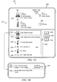
- FIGS. 5A and 5B illustrate an embodiment of removable secondary display module 110 aggregating data for electronic devices 100 , specifically cellular telephone 130 , hands-free device 132 , desktop computer 150 , and heart monitor 170 .
- display module 210 may present any information from any electronic device 100 . It should also be noted that display module 210 may present and organize information in any format.
- Display unit 212 comprises a GUI 502 and an email message 531 .
- GUI 502 comprises a device summary section 510 and a message summary section 530 .
- Device summary section 510 illustrates the electronic devices 100 from which information is collected and/or aggregated, such as the information for cellular telephone 130 , hands-free device 132 , desktop computer 150 , and heart monitor 170 . Since cellular telephone 130 is a proxy to hands-free device 132 , the information presented in display unit 212 is provided by cellular telephone 130 ( FIG. 1 ).
- a message in the illustrative embodiment, can be any type of notification relating to one of the electronic devices.
- a message can be, for example, an email message, an instant message, a voicemail message, a text message, or an alert.
- An alert is a notification which may require immediate action by the user.
- An alert can be a message regarding an operating parameter of the electronic device.
- An alert can also be a headline, such as notification of a car accident or adverse weather.
- Message summary section 530 comprises messages 531 through 536 .
- Each message comprises a graphical icon, a type of message, and a subject line.
- the graphical icon for each message indicates from which electronic device the particular message originated. However, it should be noted that the graphical icon for messages 531 through 536 can be illustrated in any format and/or presented as text.
- message summary section 530 lists the messages in time order, with the top message being the most recently received message. Alternative embodiments may list the messages in a different order, such as grouping the messages by the particular electronic devices 100 .
- Message summary section 530 also comprises several user interface buttons that allow the user to interface with display unit 500 .
- a scroll bar 540 enables the user to scroll through the messages in message summary section 530 .
- An up button 542 and a down button 546 enables the user to individually select the preceding or subsequent message, respectively.
- Enter button 544 enables the user to select and view a specific message listed in message summary section 530 .
- message 531 is selected in message summary section 530 . The details of message 531 is illustrated below GUI 502 .
- FIG. 6 is a flowchart illustrating an embodiment of a method of transmitting information by electronic devices 100 .
- the method begins at decision block 600 with electronic devices 100 determining whether new and/or updated information is available from electronic devices 100 . If new and/or updated information is available (“yes” output to block 600 ), electronic devices 100 then transmit an event to removable secondary display module 110 indicating that new and/or updated information is available (block 610 ). Instead of initiating an event, in an alternative embodiment, electronic devices 100 can wait until removable secondary display module 110 polls electronic devices 100 for the information.
- Electronic devices 100 determine whether removable secondary display module 110 wishes to receive the information (block 620 ). If removable secondary display module 110 wishes to receive the information (“yes” output to block 620 ), then electronic devices 100 transmits the information to removable secondary display module 110 (block 630 ), with the method terminating thereafter.
- FIG. 7 is a flow chart illustrating an embodiment of a method of presenting display information on removable secondary display module 110 .
- the method begins at decision block 700 with removable secondary display module 110 determining whether new and/or updated information is available.
- Removable secondary display module 110 can either poll electronic devices 100 for the information or receive an event from the at least one electronic device indicating that the information is available. If new and/or updated information is available (“yes” output to block 700 ), then removable secondary display module 110 receives the information from electronic devices 100 (block 710 ).
- Removable secondary display module 110 then reads the data tags and subject line of the information (block 720 ).
- Removable secondary display module 110 determines whether a duplicate message exists (block 730 ). If a duplicate message exists (“yes” output to block 730 ), removable secondary display module 110 deletes the duplicate message (block 735 ) and proceeds to block 740 .
- removable secondary display module 110 aggregates the received information (block 740 ). Removable secondary display module 110 then determines the format to present the updated information (block 745 ). In response to identifying the format, removable secondary display module 110 formats the information (block 750 ) and then sends the information to removable secondary display module 110 to be presented to the user (block 760 ). The method terminates thereafter.
- removable secondary display module 110 then one or more polls electronic devices 100 (block 770 ). The method then repeats with block 700 .
- Embodiments may be implemented in software and can be adapted to run on different platforms and operating systems.
- functions implemented by removable secondary display module 110 may be provided by an ordered listing of executable instructions that can be embodied in any computer-readable medium for use by or in connection with an instruction execution system, apparatus, or device, such as a computer-based system, processor-containing system, or other system that can fetch the instructions from the instruction execution system, apparatus, or device and execute the instructions.
- a “computer-readable medium” can be any means that can contain, store, communicate, propagate or transport the program for use by or in connection with the instruction execution system, apparatus, or device.
- the computer-readable medium can be, for example, but is not limited to, an electronic, magnetic, optical, electromagnetic, infrared, or semi-conductor system, apparatus, device, or propagation medium.
- Removable secondary display module 110 is small and easy to carry around. Furthermore, removable secondary display module 110 is configurable to easily fit a variety of different types of electronic devices 100 . In addition, removable secondary display module 110 consolidates all the information from a variety of different electronic devices 100 into one device, and, in some embodiments, condenses such information for viewing by a user.
Abstract
Description
Claims (24)
Priority Applications (3)
| Application Number | Priority Date | Filing Date | Title |
|---|---|---|---|
| US11/799,216 US8856394B2 (en) | 2007-04-30 | 2007-04-30 | Method and apparatus for a dockable display module |
| PCT/US2008/005357 WO2008136937A2 (en) | 2007-04-30 | 2008-04-24 | Method and apparatus for a dockable display module |
| TW097115007A TW200903321A (en) | 2007-04-30 | 2008-04-24 | Method and apparatus for a dockable display module |
Applications Claiming Priority (1)
| Application Number | Priority Date | Filing Date | Title |
|---|---|---|---|
| US11/799,216 US8856394B2 (en) | 2007-04-30 | 2007-04-30 | Method and apparatus for a dockable display module |
Publications (2)
| Publication Number | Publication Date |
|---|---|
| US20080266205A1 US20080266205A1 (en) | 2008-10-30 |
| US8856394B2 true US8856394B2 (en) | 2014-10-07 |
Family
ID=39886331
Family Applications (1)
| Application Number | Title | Priority Date | Filing Date |
|---|---|---|---|
| US11/799,216 Active 2033-07-15 US8856394B2 (en) | 2007-04-30 | 2007-04-30 | Method and apparatus for a dockable display module |
Country Status (3)
| Country | Link |
|---|---|
| US (1) | US8856394B2 (en) |
| TW (1) | TW200903321A (en) |
| WO (1) | WO2008136937A2 (en) |
Families Citing this family (11)
| Publication number | Priority date | Publication date | Assignee | Title |
|---|---|---|---|---|
| US8856394B2 (en) | 2007-04-30 | 2014-10-07 | Qualcomm Incorporated | Method and apparatus for a dockable display module |
| US10375223B2 (en) * | 2008-08-28 | 2019-08-06 | Qualcomm Incorporated | Notifying a user of events in a computing device |
| US8019903B2 (en) * | 2009-03-27 | 2011-09-13 | Microsoft Corporation | Removable accessory for a computing device |
| US8983535B2 (en) * | 2009-04-03 | 2015-03-17 | Ubiquity Broadcasting Corporation | Medical scan clip on |
| US20110191478A1 (en) * | 2010-01-29 | 2011-08-04 | International Business Organization Name Machines Corporation | Quick access display |
| DE102010055858A1 (en) * | 2010-12-22 | 2012-06-28 | Audi Ag | Output from a first receiving device and messages received from a second receiving device |
| US8300777B1 (en) * | 2011-09-25 | 2012-10-30 | Google Inc. | Divided call history user interface |
| US20150195390A1 (en) * | 2014-01-09 | 2015-07-09 | Sheng-Chun Lin | Separable Mobile Communication Device and Method |
| EP4027215A1 (en) * | 2014-09-04 | 2022-07-13 | Leomo, Inc. | Information terminal device, motion capture system and motion capture method |
| WO2019004670A1 (en) * | 2017-06-30 | 2019-01-03 | Samsung Electronics Co., Ltd. | Method and electronic device for rendering scalable vector graphics content |
| US10983987B2 (en) * | 2018-01-05 | 2021-04-20 | Telenav, Inc. | Navigation system with update mechanism and method of operation thereof |
Citations (15)
| Publication number | Priority date | Publication date | Assignee | Title |
|---|---|---|---|---|
| US6115618A (en) * | 1998-02-24 | 2000-09-05 | Motorola, Inc. | Portable electronic device with removable display |
| WO2000060450A1 (en) | 1999-04-07 | 2000-10-12 | Khyber Technologies Corporation | Portable computing, communication and entertainment device with central processor carried in a detachable handset |
| US6266539B1 (en) * | 1998-06-12 | 2001-07-24 | Cisco Technology, Inc. | Telephone docking station for personal digital assistant |
| US20020032386A1 (en) | 2000-04-17 | 2002-03-14 | Sackner Marvin A. | Systems and methods for ambulatory monitoring of physiological signs |
| US20020107800A1 (en) | 2000-12-25 | 2002-08-08 | Minoru Kadowaki | Automated teller machine and centralized managing system |
| US20040172481A1 (en) * | 2001-05-11 | 2004-09-02 | Engstrom G. Eric | Method and system for collecting and displaying aggregate presence information for mobile media players |
| US20040266480A1 (en) | 2003-06-27 | 2004-12-30 | Hjelt Kari Tapani | System and method for implementing sensor functionality in mobile devices |
| US20050066006A1 (en) | 2003-09-18 | 2005-03-24 | Vulcan Portals Inc. | Low power email functionality for an electronic device |
| TWM275445U (en) | 2005-01-31 | 2005-09-11 | Inventec Multimedia & Telecom | Multimedia display device having detachable display panel |
| US6961237B2 (en) * | 2001-07-16 | 2005-11-01 | Hewlett-Packard Development Company, L.P. | Portable computer with integrated PDA I/O docking cradle |
| US7047339B2 (en) | 2003-06-27 | 2006-05-16 | Intel Corporation | Computer system with detachable always-on portable device |
| US20060123053A1 (en) * | 2004-12-02 | 2006-06-08 | Insignio Technologies, Inc. | Personalized content processing and delivery system and media |
| US20060155914A1 (en) * | 2005-01-07 | 2006-07-13 | Apple Computer, Inc. | Highly portable media device |
| US20070086724A1 (en) * | 2002-07-17 | 2007-04-19 | Jeff Grady | Interface systems for portable digital media storage and playback devices |
| WO2008136937A2 (en) | 2007-04-30 | 2008-11-13 | Hewlett-Packard Development Company, L.P. | Method and apparatus for a dockable display module |
-
2007
- 2007-04-30 US US11/799,216 patent/US8856394B2/en active Active
-
2008
- 2008-04-24 TW TW097115007A patent/TW200903321A/en unknown
- 2008-04-24 WO PCT/US2008/005357 patent/WO2008136937A2/en active Application Filing
Patent Citations (17)
| Publication number | Priority date | Publication date | Assignee | Title |
|---|---|---|---|---|
| US6115618A (en) * | 1998-02-24 | 2000-09-05 | Motorola, Inc. | Portable electronic device with removable display |
| US6266539B1 (en) * | 1998-06-12 | 2001-07-24 | Cisco Technology, Inc. | Telephone docking station for personal digital assistant |
| WO2000060450A1 (en) | 1999-04-07 | 2000-10-12 | Khyber Technologies Corporation | Portable computing, communication and entertainment device with central processor carried in a detachable handset |
| CN1313968A (en) | 1999-04-07 | 2001-09-19 | 基伯技术公司 | Portable computing, communication and entertainment device with central processor carried in a detachable handset |
| US7831276B2 (en) * | 1999-04-07 | 2010-11-09 | Khyber Technologies Corporation | Portable computing, communication and entertainment device with central processor carried in a detachable handset |
| US20020032386A1 (en) | 2000-04-17 | 2002-03-14 | Sackner Marvin A. | Systems and methods for ambulatory monitoring of physiological signs |
| US20020107800A1 (en) | 2000-12-25 | 2002-08-08 | Minoru Kadowaki | Automated teller machine and centralized managing system |
| US20040172481A1 (en) * | 2001-05-11 | 2004-09-02 | Engstrom G. Eric | Method and system for collecting and displaying aggregate presence information for mobile media players |
| US6961237B2 (en) * | 2001-07-16 | 2005-11-01 | Hewlett-Packard Development Company, L.P. | Portable computer with integrated PDA I/O docking cradle |
| US20070086724A1 (en) * | 2002-07-17 | 2007-04-19 | Jeff Grady | Interface systems for portable digital media storage and playback devices |
| US20040266480A1 (en) | 2003-06-27 | 2004-12-30 | Hjelt Kari Tapani | System and method for implementing sensor functionality in mobile devices |
| US7047339B2 (en) | 2003-06-27 | 2006-05-16 | Intel Corporation | Computer system with detachable always-on portable device |
| US20050066006A1 (en) | 2003-09-18 | 2005-03-24 | Vulcan Portals Inc. | Low power email functionality for an electronic device |
| US20060123053A1 (en) * | 2004-12-02 | 2006-06-08 | Insignio Technologies, Inc. | Personalized content processing and delivery system and media |
| US20060155914A1 (en) * | 2005-01-07 | 2006-07-13 | Apple Computer, Inc. | Highly portable media device |
| TWM275445U (en) | 2005-01-31 | 2005-09-11 | Inventec Multimedia & Telecom | Multimedia display device having detachable display panel |
| WO2008136937A2 (en) | 2007-04-30 | 2008-11-13 | Hewlett-Packard Development Company, L.P. | Method and apparatus for a dockable display module |
Non-Patent Citations (3)
| Title |
|---|
| Office Action, Application No. TW 97115007, Date of Issuance: Sep. 14, 2013, pp. 1-7. |
| Taiwan Search Report-TW097115007-TIPO-Mar. 27, 2014. |
| Taiwan Search Report—TW097115007—TIPO—Mar. 27, 2014. |
Also Published As
| Publication number | Publication date |
|---|---|
| WO2008136937A2 (en) | 2008-11-13 |
| WO2008136937A3 (en) | 2008-12-31 |
| US20080266205A1 (en) | 2008-10-30 |
| TW200903321A (en) | 2009-01-16 |
Similar Documents
| Publication | Publication Date | Title |
|---|---|---|
| US8856394B2 (en) | Method and apparatus for a dockable display module | |
| US10715567B2 (en) | Method and apparatus for providing state information | |
| KR101613657B1 (en) | Wireless synchronization of media content and subscription content | |
| CN106557330B (en) | Method and device for processing notification information of notification bar of mobile terminal system and mobile terminal | |
| JP5001423B2 (en) | Method, system, and mobile device for prioritizing a discovered device list | |
| EP2218187B1 (en) | Modifying mobile device operation using proximity relationships | |
| US9119052B2 (en) | Content sharing for mobile devices | |
| EP1237333A1 (en) | Information processing method and information processing apparatus having communication function | |
| US7925754B2 (en) | Method and computer program product to provide synch notifications to client devices | |
| US8307062B2 (en) | Standardized mechanism of remote management of embedded radio modules | |
| US9811999B2 (en) | Methods for automated response to distress signals | |
| CN109725975A (en) | Message is by the reminding method, device and electronic equipment of read states | |
| CN106681860B (en) | A kind of data back up method and data backup device | |
| KR20020026381A (en) | Radio communication system, radio communication apparatus, and radio communicating method | |
| WO2023065931A1 (en) | Method for charging electronic device, and electronic device | |
| KR20110082881A (en) | Convergence method and apparatus for the vehicle on the basis of cellular phone connectivity | |
| CN103188628B (en) | For mobile terminal and the method thereof of shared personal electric information | |
| JP2010086326A (en) | Mobile terminal, client terminal, communication system, and mobile terminal program | |
| CN114371895B (en) | Terminal equipment, mail marking method and storage medium | |
| US8458320B2 (en) | Alerting a user to an occurrence of a specified event | |
| GB2432998A (en) | Data storage device and method | |
| CN117743654A (en) | Message filtering method, electronic equipment and storage medium | |
| CN114640741A (en) | Unread message management method and unread message management equipment |
Legal Events
| Date | Code | Title | Description |
|---|---|---|---|
| AS | Assignment |
Owner name: HEWLETT-PACKARD DEVELOPMENT COMPANY, L.P., TEXAS Free format text: ASSIGNMENT OF ASSIGNORS INTEREST;ASSIGNOR:MOEHRING, CHRIS;REEL/FRAME:019324/0658 Effective date: 20070430 |
|
| AS | Assignment |
Owner name: PALM, INC., CALIFORNIA Free format text: ASSIGNMENT OF ASSIGNORS INTEREST;ASSIGNOR:HEWLETT-PACKARD DEVELOPMENT COMPANY, L.P.;REEL/FRAME:030341/0459 Effective date: 20130430 |
|
| FEPP | Fee payment procedure |
Free format text: PAYER NUMBER DE-ASSIGNED (ORIGINAL EVENT CODE: RMPN); ENTITY STATUS OF PATENT OWNER: LARGE ENTITY Free format text: PAYOR NUMBER ASSIGNED (ORIGINAL EVENT CODE: ASPN); ENTITY STATUS OF PATENT OWNER: LARGE ENTITY |
|
| AS | Assignment |
Owner name: HEWLETT-PACKARD DEVELOPMENT COMPANY, L.P., TEXAS Free format text: ASSIGNMENT OF ASSIGNORS INTEREST;ASSIGNOR:PALM, INC.;REEL/FRAME:031837/0659 Effective date: 20131218 Owner name: PALM, INC., CALIFORNIA Free format text: ASSIGNMENT OF ASSIGNORS INTEREST;ASSIGNOR:HEWLETT-PACKARD DEVELOPMENT COMPANY, L.P.;REEL/FRAME:031837/0544 Effective date: 20131218 Owner name: HEWLETT-PACKARD DEVELOPMENT COMPANY, L.P., TEXAS Free format text: ASSIGNMENT OF ASSIGNORS INTEREST;ASSIGNOR:PALM, INC.;REEL/FRAME:031837/0239 Effective date: 20131218 |
|
| AS | Assignment |
Owner name: QUALCOMM INCORPORATED, CALIFORNIA Free format text: ASSIGNMENT OF ASSIGNORS INTEREST;ASSIGNORS:HEWLETT-PACKARD COMPANY;HEWLETT-PACKARD DEVELOPMENT COMPANY, L.P.;PALM, INC.;REEL/FRAME:032132/0001 Effective date: 20140123 |
|
| STCF | Information on status: patent grant |
Free format text: PATENTED CASE |
|
| MAFP | Maintenance fee payment |
Free format text: PAYMENT OF MAINTENANCE FEE, 4TH YEAR, LARGE ENTITY (ORIGINAL EVENT CODE: M1551) Year of fee payment: 4 |
|
| MAFP | Maintenance fee payment |
Free format text: PAYMENT OF MAINTENANCE FEE, 8TH YEAR, LARGE ENTITY (ORIGINAL EVENT CODE: M1552); ENTITY STATUS OF PATENT OWNER: LARGE ENTITY Year of fee payment: 8 |